EP1729142A1 - Long magnetic sensor - Google Patents
Long magnetic sensor Download PDFInfo
- Publication number
- EP1729142A1 EP1729142A1 EP05720115A EP05720115A EP1729142A1 EP 1729142 A1 EP1729142 A1 EP 1729142A1 EP 05720115 A EP05720115 A EP 05720115A EP 05720115 A EP05720115 A EP 05720115A EP 1729142 A1 EP1729142 A1 EP 1729142A1
- Authority
- EP
- European Patent Office
- Prior art keywords
- magnetosensitive
- longitudinal direction
- intervals
- magnetosensitive elements
- magnetic sensor
- Prior art date
- Legal status (The legal status is an assumption and is not a legal conclusion. Google has not performed a legal analysis and makes no representation as to the accuracy of the status listed.)
- Granted
Links
Images




Classifications
-
- G—PHYSICS
- G01—MEASURING; TESTING
- G01R—MEASURING ELECTRIC VARIABLES; MEASURING MAGNETIC VARIABLES
- G01R33/00—Arrangements or instruments for measuring magnetic variables
- G01R33/02—Measuring direction or magnitude of magnetic fields or magnetic flux
- G01R33/06—Measuring direction or magnitude of magnetic fields or magnetic flux using galvano-magnetic devices
- G01R33/09—Magnetoresistive devices
Definitions
- the present invention relates to elongated magnetic sensors for detecting magnetic patterns printed on, for example, bills.
- a variety of elongated magnetic sensors have been commercialized as magnetic sensors for identifying objects, such as bills and securities, having predetermined magnetic patterns printed thereon with, for example, magnetic ink.
- an elongated magnetic sensor 200 includes a case 1' and magnetoresistive (MR) devices 21A to 21E arranged linearly in the longitudinal direction of the case 1' with no intervals therebetween.
- the magnetoresistive devices 21A to 21E include magnetosensitive parts 22A to 22E, respectively.
- the magnetosensitive parts 22A to 22E each include two magnetosensitive element arrays extending in the longitudinal direction.
- the elongated magnetic sensor 200 also includes connection electrodes 23A to 23E electrically connected to the magnetosensitive parts 22A to 22E, respectively (three electrodes for each magnetosensitive part); external connection terminals 24A to 24E disposed on the case 1' and connected to the connection electrodes 23A to 23E, respectively; and a permanent magnet (not shown) disposed on the back surface of the case 1' to apply a magnetic field to the magnetosensitive parts 22A to 22E.
- the elongated magnetic sensor 200 senses changes in the magnetic field (changes in magnetic flux density) due to a magnetic pattern formed on an object being conveyed perpendicularly to the longitudinal direction (in the lateral direction) with the magnetosensitive elements to detect the object (see Patent Document 1).
- Magnetosensitive parts used for such an elongated magnetic sensor each include separate magnetosensitive elements that are combined to achieve larger changes in the resistance of magnetoresistive devices due to changes in the magnetic field, as disclosed in Fig. 4 of Patent Document 2.
- a magnetosensitive part shown in Fig. 4 of Patent Document 2 includes magnetosensitive elements arranged longitudinally at intervals, connection conductors electrically connecting the magnetosensitive elements, and terminal electrodes electrically connected to external connection electrodes.
- Fig. 8(A) is an enlarged plan view of the magnetoresistive device 21C of the elongated magnetic sensor 200 shown in Fig. 7 in the case where it has an inner structure shown in Fig. 4 of Patent Document 2.
- Fig. 8(B) is a partial plan view showing the arrangement of the magnetoresistive devices 21B to 21D.
- the magnetosensitive part 22C of the magnetoresistive device 21C includes magnetosensitive elements 221C arranged longitudinally at intervals D1, magnetosensitive elements 222C arranged in parallel with the magnetosensitive elements 221C, connection conductors 223C connecting the magnetosensitive elements 221C in series, and connection conductors 224C connecting the magnetosensitive elements 222C in series.
- the magnetosensitive part 22C also includes a terminal electrode 227C electrically connected to an end of the series connection of the magnetosensitive elements 221C through a connection conductor 2251C, a terminal electrode 226C electrically connected to an end of the series connection of the magnetosensitive elements 222C through a connection conductor 2252C, and a terminal electrode 228C electrically connected to the other ends of the series connections of the magnetosensitive elements 221C and 222C through a connection conductor 2253C.
- Patent Document 1 Japanese Patent No. 2921262
- Patent Document 2 Japanese Unexamined Patent Application Publication No. 2003-107142
- the intervals D1 between the magnetosensitive elements are adjusted so that a detection output produced when a magnetic pattern passes across the intervals D1 is nearly the same as that produced when the magnetic pattern passes across the magnetosensitive elements.
- the intervals D2 between the magnetosensitive elements nearest the contact surfaces of the adjacent magnetoresistive devices are larger than the intervals D1.
- the magnetosensitive parts cannot be extended to the ends of the magnetoresistive devices because a wafer serving as a mother board for the magnetoresistive devices is separated into the magnetoresistive devices by dicing or laser cutting. That is, predetermined cutting margins are defined so as not to cut the magnetosensitive parts.
- the connection conductors are formed at the ends of the magnetosensitive element arrays in the longitudinal direction. Even if the magnetoresistive devices are disposed with the longitudinal ends thereof in contact with each other, the intervals between the magnetosensitive elements nearest the opposite ends of the adjacent magnetosensitive elements cannot be narrower than the areas used for the cutting margins and the connection conductors. When a magnetic pattern passes across the intervals D2, therefore, the elongated magnetic sensor 200 may exhibit a significant decrease in detection output and thus fail to detect the magnetic pattern.
- an object of the present invention is to provide an elongated magnetic sensor capable of achieving a stable detection output at any position thereof in the longitudinal direction.
- An elongated magnetic sensor includes magnetoresistive devices arranged in the longitudinal direction thereof, each including a magnetosensitive part having magnetosensitive elements arranged at intervals in the longitudinal direction and connection conductors connecting the magnetosensitive elements in series.
- the intervals between the magnetosensitive elements disposed at the opposite ends of the adjacent magnetoresistive devices in the longitudinal direction are smaller than or equal to the intervals between the adjacent magnetosensitive elements within each of the magnetoresistive devices in the longitudinal direction.
- the magnetic pattern varies a magnetic flux passing through the magnetosensitive parts to change the resistance of the magnetosensitive elements.
- the adjacent magnetosensitive elements within each of the magnetoresistive devices are arranged in such intervals that a detection output produced when the magnetic pattern passes across the intervals is nearly equal to, or only slightly lower than, a detection output produced when the magnetic pattern passes across the magnetosensitive elements.
- the intervals between the magnetosensitive elements nearest the opposite ends of the adjacent magnetoresistive devices are smaller than or equal to the intervals between the adjacent magnetosensitive elements within each of the magnetoresistive devices.
- the magnetosensitive elements may be disposed in proximity to the opposite ends of the adjacent magnetoresistive devices by employing, for example, a structure as shown in Fig. 2 in which magnetosensitive elements are formed near the ends of magnetoresistive devices in the longitudinal direction, rather than by employing a structure as shown in Fig. 8(A) in which connection conductors are formed at the ends of magnetoresistive devices in the longitudinal direction.
- the intervals between the magnetosensitive elements disposed at the opposite ends of the adjacent magnetoresistive devices in the longitudinal direction are substantially equal to the intervals between the adjacent magnetosensitive elements within each of the magnetoresistive devices in the longitudinal direction.
- This structure allows the elongated magnetic sensor to produce a substantially uniform detection output in the longitudinal direction because the intervals between the magnetosensitive elements of the adjacent magnetoresistive devices in the longitudinal direction are equal to the intervals between the magnetosensitive elements within each of the magnetoresistive devices in the longitudinal direction.
- the magnetosensitive part includes first and second magnetosensitive element arrays arranged perpendicularly to the longitudinal direction.
- the magnetosensitive elements are arranged such that the positions of the magnetosensitive elements of the first magnetosensitive element array in the longitudinal direction, when viewed in the lateral direction, differ from those of the magnetosensitive elements of the second magnetosensitive element array in the longitudinal direction.
- the magnetosensitive elements are arranged in two arrays such that the positions of the magnetosensitive elements in the longitudinal direction differ between the two arrays.
- the intervals between the diagonally adjacent magnetosensitive elements within each of the magnetoresistive devices in the longitudinal direction are smaller than in the case where the magnetosensitive elements of the two arrays are arranged at the same positions in the longitudinal direction.
- the intervals between the diagonally adjacent magnetosensitive elements disposed at the opposite ends of the adjacent magnetoresistive devices in the longitudinal direction may be reduced according to the intervals between the adjacent magnetosensitive elements within each of the magnetoresistive devices. This reduces the area that is not covered by the magnetosensitive elements in the longitudinal direction to further stabilize the detection output.
- connection conductors are not formed at the ends of the magnetoresistive devices in the longitudinal direction.
- each magnetoresistive device has conductors formed at the ends thereof in the longitudinal direction to connect a magnetosensitive part to terminal electrodes adjacent to either long side of the magnetoresistive device and to connect magnetosensitive elements to each other.
- each magnetoresistive device has no connection conductors at the ends thereof because terminal electrodes are disposed adjacent to both sides of the magnetoresistive device in the longitudinal direction.
- the magnetosensitive elements can be formed in regions where connection conductors would be formed in the known structure to minimize the intervals between the magnetosensitive elements formed at the opposite ends of the magnetoresistive devices. Accordingly, the overall pitch of the magnetosensitive elements can be reduced to stabilize the detection output.
- the intervals between the magnetosensitive elements nearest the opposite ends of the adjacent magnetoresistive devices are smaller than or equal to the intervals between the adjacent magnetosensitive elements within each of the magnetoresistive devices.
- the elongated magnetic sensor exhibits little decrease in detection output when a magnetic pattern passes across any region of the elongated magnetic sensor in the longitudinal direction. The elongated magnetic sensor can therefore stably and reliably detect a magnetic pattern on an object being conveyed in the lateral direction.
- the magnetosensitive elements are arranged in two arrays such that the positions of the magnetosensitive elements in the longitudinal direction differ between the two arrays.
- the elongated magnetic sensor can therefore produce a more stable detection output in the longitudinal direction with reduced intervals between the adjacent magnetosensitive elements in the longitudinal direction.
- connection conductors are not formed at the ends of the magnetoresistive devices in the longitudinal direction.
- the intervals between the magnetosensitive elements formed at the opposite ends of the magnetoresistive devices can be reduced so that the elongated magnetic sensor can produce a more stable detection output.
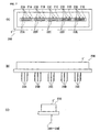
- Fig. 1(A) is a plan view of the elongated magnetic sensor according to this embodiment.
- Fig. 1(B) is a side view showing a long side of the elongated magnetic sensor.
- Fig. 1(C) is a side view showing a short side of the elongated magnetic sensor.
- an elongated magnetic sensor 100 includes a case 1 and magnetoresistive (MR) devices 11A to 11E arranged linearly in the longitudinal direction of the case 1.
- the magnetoresistive devices 11A to 11E include magnetosensitive parts 12A to 12E, respectively, with the longitudinal direction thereof being in parallel with that of the magnetoresistive devices 11A to 11E.
- the elongated magnetic sensor 100 also includes connection electrodes 13A to 13E extending from ends of the magnetoresistive devices 11A to 11E, respectively, in the lateral direction thereof (three electrodes for each magnetoresistive device) and external connection terminals 14A to 14E protruding from the back surface of the case 1 (opposite the surface on which the magnetoresistive devices 11A to 11E are formed) and having a predetermined length (three terminals for each magnetoresistive device).
- the connection electrodes 13A to 13E and the external connection terminals 14A to 14E are arranged in the longitudinal direction.
- connection electrodes 13A to 13E are electrically connected to the external connection terminals 14A to 14E, respectively; for example, the three connection electrodes 13A are connected to the three corresponding external connection terminals 14A.
- a groove (not shown) is formed in a region on the back surface of the case 1 opposite the magnetoresistive devices 11A to 11E.
- a permanent magnet (not shown) is disposed in the groove to apply a predetermined magnetic field to the magnetosensitive parts 12A to 12E.
- the structure of the magnetoresistive devices 11A to 11E is then described with reference to Fig. 2.
- the magnetoresistive device 11c is herein described as an example because the magnetoresistive devices 11A to 11E have the same structure.
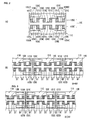
- Fig. 2(A) is an enlarged plan view of the magnetoresistive device 11C of the elongated magnetic sensor 100 shown in Fig. 1.
- Fig. 2(B) is a partial plan view showing the arrangement of the magnetoresistive devices 11B to 11D.
- the magnetoresistive device 11C includes magnetosensitive elements 121C and 122C arranged longitudinally at the same intervals D1.
- the positions of the magnetosensitive elements 121C and 122C are different laterally but are aligned longitudinally.
- the adjacent magnetosensitive elements 121C are connected in series through connection conductors 123C.
- the magnetosensitive elements 121C are connected in a meander pattern with the intervals therebetween to form a first magnetosensitive element array 120C.
- the magnetosensitive elements 121C at the ends of the magnetoresistive device 11C in the longitudinal direction are electrically connected to terminal electrodes 126C and 127C through connection electrodes 1251C and 1252C, respectively.
- the terminal electrodes 126C and 127C are formed outside the first magnetosensitive element array 120C in the lateral direction (on the top side thereof in Fig. 2).
- the terminal electrode 126C is connected to one of the outer connection terminals 13C while the terminal electrode 127C is connected to the inner connection terminal 13C.
- the adjacent magnetosensitive elements 122C are connected in series through connection conductors 124C.
- the magnetosensitive elements 122C are connected in a meander pattern with the intervals therebetween to form a second magnetosensitive element array 120C'.
- the magnetosensitive elements 122C at the ends of the magnetoresistive device 11C in the longitudinal direction are electrically connected to terminal electrodes 128C and 129C through connection electrodes 1253C and 1253C, respectively.
- the terminal electrodes 128C and 129C are formed outside the second magnetosensitive element array 120C' in the lateral direction (on the bottom side thereof in Fig. 2), that is, on the side opposite the terminal electrodes 126C and 127C.
- the terminal electrode 128C is connected to the inner connection terminal 13C while the terminal electrode 129C is connected to the other outer connection terminal 13C.
- the outermost magnetosensitive elements 121C of the first magnetosensitive element array 120C and the outermost magnetosensitive elements 122C of the second magnetosensitive element array 120C' are formed in the vicinities of the ends of the magnetoresistive device 11C in the longitudinal direction.
- the outermost magnetosensitive elements of the magnetosensitive element arrays are formed in the vicinities of the ends of the magnetoresistive device 11C in the longitudinal direction with consideration given to the cutting accuracy with which a wafer is cut into the magnetoresistive devices.
- the intervals between the magnetosensitive elements formed at the opposite ends of the adjacent magnetoresistive devices can be smaller than in the known art, that is, in the case where connection conductors are formed at the ends of magnetoresistive devices in the longitudinal direction.
- the magnetic pattern passes near the surface of the elongated magnetic sensor 100 on the magnetoresistive device side.
- the magnetic pattern on the object then varies the magnetic field of the permanent magnet to change the density of the magnetic flux passing through the magnetosensitive elements positioned in the region where the magnetic pattern passes.
- the resistance of the magnetosensitive elements changes in response to the change in the flux density.
- the elongated magnetic sensor 100 senses the change in resistance to detect the magnetic pattern.
- the external connection terminals 14A to 14C are connected to positive voltage terminals, grounding terminals, and negative voltage terminals so that the elongated magnetic sensor 100 senses the change in the resistance of the magnetosensitive elements according to the change in the current passing through the terminals to detect the magnetic pattern.
- all magnetosensitive elements can be disposed at regular intervals across the ends of the magnetoresistive devices 11A to 11E to produce a substantially constant detection output irrespective of where the magnetic pattern passes in the longitudinal direction of the elongated magnetic sensor 100. That is, the elongated magnetic sensor 100 can avoid problems in the known art, including a significant decrease in detection output resulting between magnetoresistive devices and a time difference in detection output between magnetoresistive devices.
- an elongated magnetic sensor can be provided which can stably and reliably detect a magnetic pattern irrespective of, for example, where the magnetic pattern is formed on an object.
- Fig. 3 is a partial plan view showing the arrangement of the magnetoresistive devices 11B to 11D of the elongated magnetic sensor according to this embodiment.
- the intervals D2 between the opposite magnetosensitive elements of the adjacent magnetoresistive devices are smaller than the intervals D1 between the magnetosensitive elements within each magnetoresistive device.
- the rest of the structure is the same as the elongated magnetic sensor according to the first embodiment.
- This structure can prevent a decrease in the detection output produced when a magnetic pattern passes between the opposite ends of the adjacent magnetoresistive devices relative to that produced when the magnetic pattern passes across the magnetoresistive devices. If the intervals D2 are extremely smaller than the intervals D1, a larger detection output is produced when a magnetic pattern passes across the intervals D2, that is, between the adjacent magnetoresistive devices, than when the magnetic pattern passes across the magnetoresistive devices. In that case, the magnetic pattern may be detected by controlling the detection output produced in the intervals D2. The elongated magnetic sensor can therefore reliably detect the magnetic pattern.
- the intervals D2 between the opposite magnetosensitive elements of the adjacent magnetoresistive devices are smaller than the intervals D1 between the magnetosensitive elements within each magnetoresistive device.
- the intervals D2 do not necessarily have to agree with the intervals D1, so that the magnetoresistive devices can readily be arranged. While regular intervals, as in the first embodiment, may be difficult to precisely define between magnetoresistive devices in actual manufacturing processes, the structure according to the second embodiment can relatively easily be achieved because slight errors such as intervals D1 > intervals D2 are allowable. The second embodiment can therefore provide a higher yield of elongated magnetic sensors than the first embodiment.
- the second embodiment allows the production of elongated magnetic sensors without decreasing the yield thereof in case of an error associated with an arrangement step in manufacturing processes.
- Fig. 4(A) is an enlarged plan view of the magnetoresistive device 11C of the elongated magnetic sensor according to this embodiment.
- Fig. 4(B) is a partial plan view showing the arrangement of the magnetoresistive devices 11B to 11D.
- the positions of the magnetosensitive elements 121C of the first magnetosensitive element array 120C are different in the longitudinal direction from those of the magnetosensitive elements 122C of the second magnetosensitive element array 120C'.
- the magnetosensitive elements 122C are disposed at positions corresponding to the centers between the adjacent magnetosensitive elements 121C.
- the magnetosensitive elements 121C and 122C which are diagonally adjacent with respect to the longitudinal direction, are arranged at intervals D3 in the longitudinal direction. The intervals D3 are smaller than the intervals D1 in the first and second embodiments.
- the diagonally opposite magnetosensitive elements of the adjacent magnetoresistive devices are arranged at intervals D4 equal to the intervals D3.
- the rest of the structure is the same as the elongated magnetic sensor according to the first embodiment.
- the elongated magnetic sensor having the structure described above can reliably detect a magnetic pattern irrespective of where the magnetic pattern passes, as in the first embodiment.
- the elongated magnetic sensor can produce a more stable detection output because the intervals between the magnetosensitive elements in the longitudinal direction are smaller than those in the first embodiment and thus the area that is not covered by the magnetosensitive elements is reduced in the longitudinal direction.
- Fig. 5 is a partial plan view showing the arrangement of the magnetoresistive devices 11B to 11D of the elongated magnetic sensor according to this embodiment.
- the intervals D4 between the diagonally opposite magnetosensitive elements of the adjacent magnetoresistive devices are smaller than the intervals D3 between the diagonally adjacent magnetosensitive elements within each magnetoresistive device.
- the rest of the structure is the same as the elongated magnetic sensor according to the third embodiment.
- the elongated magnetic sensor having the structure described above has the same advantages as in the third embodiment and can be produced without decreasing yield in case of an error associated with manufacturing processes, as in the second embodiment.
- magnetosensitive parts are formed in a meander pattern in the embodiments described above, they may also be formed in a linear pattern in the longitudinal direction, as shown in Fig. 6.
- Fig. 6 shows enlarged plan views of an elongated magnetic sensor in which the magnetosensitive element arrays 120C and 120C' of the magnetosensitive parts are formed in a linear pattern.
- Fig. 6(A) is an enlarged plan view of the magnetoresistive device 11C.
- Fig. 6(B) is a partial plan view showing the arrangement of the magnetoresistive devices 11B to 11D.
- the magnetosensitive part 12C includes the first magnetosensitive element array 120C, in which the magnetosensitive elements 121C and the connection conductors 123C are alternately connected in the longitudinal direction, and the second magnetosensitive element array 120C', in which the magnetosensitive elements 122C and the connection conductors 124C are alternately connected in the longitudinal direction.
- the intervals D6 between the opposite magnetosensitive elements of the adjacent magnetoresistive devices are smaller than or equal to the intervals D5 between the magnetosensitive elements within each magnetoresistive device.
- the rest of the structure is the same as the elongated magnetic sensor according to the first embodiment.
- This structure has the advantage of stably and reliably detecting a magnetic pattern irrespective of where the magnetic pattern passes, as in the first and second embodiments.
- the positions of the magnetosensitive elements in the longitudinal direction may differ between the two parallel magnetosensitive element arrays, as in the third and fourth embodiments.
- Such a structure has the advantage of more stably detecting a magnetic pattern, as in the third and fourth embodiments.
Landscapes
- Physics & Mathematics (AREA)
- Condensed Matter Physics & Semiconductors (AREA)
- General Physics & Mathematics (AREA)
- Measuring Magnetic Variables (AREA)
- Hall/Mr Elements (AREA)
Abstract
Description
- The present invention relates to elongated magnetic sensors for detecting magnetic patterns printed on, for example, bills.
- A variety of elongated magnetic sensors have been commercialized as magnetic sensors for identifying objects, such as bills and securities, having predetermined magnetic patterns printed thereon with, for example, magnetic ink.
- The structure of a known elongated sensor is illustrated in Fig. 7. Fig. 7(A) is a plan view showing the magnetosensitive part side of the sensor with a cover detached therefrom. Fig. 7(B) is a side view showing a long side of the sensor in that state. Fig. 7(C) is a side view showing a short side of the sensor in that state. In this example, an elongated
magnetic sensor 200 includes a case 1' and magnetoresistive (MR)devices 21A to 21E arranged linearly in the longitudinal direction of the case 1' with no intervals therebetween. Themagnetoresistive devices 21A to 21E includemagnetosensitive parts 22A to 22E, respectively. Themagnetosensitive parts 22A to 22E each include two magnetosensitive element arrays extending in the longitudinal direction. The elongatedmagnetic sensor 200 also includesconnection electrodes 23A to 23E electrically connected to themagnetosensitive parts 22A to 22E, respectively (three electrodes for each magnetosensitive part);external connection terminals 24A to 24E disposed on the case 1' and connected to theconnection electrodes 23A to 23E, respectively; and a permanent magnet (not shown) disposed on the back surface of the case 1' to apply a magnetic field to themagnetosensitive parts 22A to 22E. The elongatedmagnetic sensor 200 senses changes in the magnetic field (changes in magnetic flux density) due to a magnetic pattern formed on an object being conveyed perpendicularly to the longitudinal direction (in the lateral direction) with the magnetosensitive elements to detect the object (see Patent Document 1). - Magnetosensitive parts used for such an elongated magnetic sensor each include separate magnetosensitive elements that are combined to achieve larger changes in the resistance of magnetoresistive devices due to changes in the magnetic field, as disclosed in Fig. 4 of Patent Document 2. A magnetosensitive part shown in Fig. 4 of Patent Document 2 includes magnetosensitive elements arranged longitudinally at intervals, connection conductors electrically connecting the magnetosensitive elements, and terminal electrodes electrically connected to external connection electrodes.
- Fig. 8(A) is an enlarged plan view of the
magnetoresistive device 21C of the elongatedmagnetic sensor 200 shown in Fig. 7 in the case where it has an inner structure shown in Fig. 4 of Patent Document 2. Fig. 8(B) is a partial plan view showing the arrangement of themagnetoresistive devices 21B to 21D. - In Fig. 8, the
magnetosensitive part 22C of themagnetoresistive device 21C includesmagnetosensitive elements 221C arranged longitudinally at intervals D1,magnetosensitive elements 222C arranged in parallel with themagnetosensitive elements 221C,connection conductors 223C connecting themagnetosensitive elements 221C in series, andconnection conductors 224C connecting themagnetosensitive elements 222C in series. Themagnetosensitive part 22C also includes aterminal electrode 227C electrically connected to an end of the series connection of themagnetosensitive elements 221C through aconnection conductor 2251C, aterminal electrode 226C electrically connected to an end of the series connection of themagnetosensitive elements 222C through aconnection conductor 2252C, and aterminal electrode 228C electrically connected to the other ends of the series connections of themagnetosensitive elements connection conductor 2253C. - The
magnetoresistive device 21C is disposed between themagnetoresistive devices
Patent Document 1:Japanese Patent No. 2921262
Patent Document 2:Japanese Unexamined Patent Application Publication No. 2003-107142 - The intervals D1 between the magnetosensitive elements are adjusted so that a detection output produced when a magnetic pattern passes across the intervals D1 is nearly the same as that produced when the magnetic pattern passes across the magnetosensitive elements. However, the intervals D2 between the magnetosensitive elements nearest the contact surfaces of the adjacent magnetoresistive devices (in Fig. 8(B), for example, the interval between the magnetosensitive elements of the
magnetosensitive part 22C nearest themagnetosensitive part 22D and the magnetosensitive elements of themagnetosensitive part 22D nearest themagnetosensitive part 22C) are larger than the intervals D1. The magnetosensitive parts cannot be extended to the ends of the magnetoresistive devices because a wafer serving as a mother board for the magnetoresistive devices is separated into the magnetoresistive devices by dicing or laser cutting. That is, predetermined cutting margins are defined so as not to cut the magnetosensitive parts. In addition, the connection conductors are formed at the ends of the magnetosensitive element arrays in the longitudinal direction. Even if the magnetoresistive devices are disposed with the longitudinal ends thereof in contact with each other, the intervals between the magnetosensitive elements nearest the opposite ends of the adjacent magnetosensitive elements cannot be narrower than the areas used for the cutting margins and the connection conductors. When a magnetic pattern passes across the intervals D2, therefore, the elongatedmagnetic sensor 200 may exhibit a significant decrease in detection output and thus fail to detect the magnetic pattern. - Accordingly, an object of the present invention is to provide an elongated magnetic sensor capable of achieving a stable detection output at any position thereof in the longitudinal direction.
- An elongated magnetic sensor according to the present invention includes magnetoresistive devices arranged in the longitudinal direction thereof, each including a magnetosensitive part having magnetosensitive elements arranged at intervals in the longitudinal direction and connection conductors connecting the magnetosensitive elements in series. The intervals between the magnetosensitive elements disposed at the opposite ends of the adjacent magnetoresistive devices in the longitudinal direction are smaller than or equal to the intervals between the adjacent magnetosensitive elements within each of the magnetoresistive devices in the longitudinal direction.
- As an object having a magnetic pattern formed thereon passes across a surface of the elongated magnetic sensor on which the magnetosensitive parts are formed in the lateral direction, the magnetic pattern varies a magnetic flux passing through the magnetosensitive parts to change the resistance of the magnetosensitive elements. The adjacent magnetosensitive elements within each of the magnetoresistive devices are arranged in such intervals that a detection output produced when the magnetic pattern passes across the intervals is nearly equal to, or only slightly lower than, a detection output produced when the magnetic pattern passes across the magnetosensitive elements. The intervals between the magnetosensitive elements nearest the opposite ends of the adjacent magnetoresistive devices are smaller than or equal to the intervals between the adjacent magnetosensitive elements within each of the magnetoresistive devices. Accordingly, the elongated magnetic sensor experiences little decrease in detection output when the magnetic pattern passes across the contact portions of the adjacent magnetoresistive devices. The magnetosensitive elements may be disposed in proximity to the opposite ends of the adjacent magnetoresistive devices by employing, for example, a structure as shown in Fig. 2 in which magnetosensitive elements are formed near the ends of magnetoresistive devices in the longitudinal direction, rather than by employing a structure as shown in Fig. 8(A) in which connection conductors are formed at the ends of magnetoresistive devices in the longitudinal direction.
- In the present invention, additionally, the intervals between the magnetosensitive elements disposed at the opposite ends of the adjacent magnetoresistive devices in the longitudinal direction are substantially equal to the intervals between the adjacent magnetosensitive elements within each of the magnetoresistive devices in the longitudinal direction.
- This structure allows the elongated magnetic sensor to produce a substantially uniform detection output in the longitudinal direction because the intervals between the magnetosensitive elements of the adjacent magnetoresistive devices in the longitudinal direction are equal to the intervals between the magnetosensitive elements within each of the magnetoresistive devices in the longitudinal direction.
- In the present invention, additionally, the magnetosensitive part includes first and second magnetosensitive element arrays arranged perpendicularly to the longitudinal direction. The magnetosensitive elements are arranged such that the positions of the magnetosensitive elements of the first magnetosensitive element array in the longitudinal direction, when viewed in the lateral direction, differ from those of the magnetosensitive elements of the second magnetosensitive element array in the longitudinal direction.
- In this structure, the magnetosensitive elements are arranged in two arrays such that the positions of the magnetosensitive elements in the longitudinal direction differ between the two arrays. The intervals between the diagonally adjacent magnetosensitive elements within each of the magnetoresistive devices in the longitudinal direction are smaller than in the case where the magnetosensitive elements of the two arrays are arranged at the same positions in the longitudinal direction. The intervals between the diagonally adjacent magnetosensitive elements disposed at the opposite ends of the adjacent magnetoresistive devices in the longitudinal direction may be reduced according to the intervals between the adjacent magnetosensitive elements within each of the magnetoresistive devices. This reduces the area that is not covered by the magnetosensitive elements in the longitudinal direction to further stabilize the detection output.
- In the present invention, additionally, the connection conductors are not formed at the ends of the magnetoresistive devices in the longitudinal direction.
- In a common structure, each magnetoresistive device has conductors formed at the ends thereof in the longitudinal direction to connect a magnetosensitive part to terminal electrodes adjacent to either long side of the magnetoresistive device and to connect magnetosensitive elements to each other. In the structure described above, by contrast, each magnetoresistive device has no connection conductors at the ends thereof because terminal electrodes are disposed adjacent to both sides of the magnetoresistive device in the longitudinal direction. As a result, the magnetosensitive elements can be formed in regions where connection conductors would be formed in the known structure to minimize the intervals between the magnetosensitive elements formed at the opposite ends of the magnetoresistive devices. Accordingly, the overall pitch of the magnetosensitive elements can be reduced to stabilize the detection output.
- According to the present invention, the intervals between the magnetosensitive elements nearest the opposite ends of the adjacent magnetoresistive devices are smaller than or equal to the intervals between the adjacent magnetosensitive elements within each of the magnetoresistive devices. The elongated magnetic sensor exhibits little decrease in detection output when a magnetic pattern passes across any region of the elongated magnetic sensor in the longitudinal direction. The elongated magnetic sensor can therefore stably and reliably detect a magnetic pattern on an object being conveyed in the lateral direction.
- According to the present invention, additionally, the magnetosensitive elements are arranged in two arrays such that the positions of the magnetosensitive elements in the longitudinal direction differ between the two arrays. The elongated magnetic sensor can therefore produce a more stable detection output in the longitudinal direction with reduced intervals between the adjacent magnetosensitive elements in the longitudinal direction.
- According to the present invention, additionally, the connection conductors are not formed at the ends of the magnetoresistive devices in the longitudinal direction. As a result, the intervals between the magnetosensitive elements formed at the opposite ends of the magnetoresistive devices can be reduced so that the elongated magnetic sensor can produce a more stable detection output.
-
- Fig. 1 shows a perspective view, a plan view, and a side view of an elongated magnetic sensor according to a first embodiment.
- Fig. 2 shows an enlarged plan view of a
magnetoresistive device 11C of the elongated magnetic sensor shown in Fig. 1 and a partial plan view showing the arrangement ofmagnetoresistive devices 11B to 11D. - Fig. 3 is a partial plan view showing the arrangement of
magnetoresistive devices 11B to 11D of an elongated magnetic sensor according to a second embodiment. - Fig. 4 shows an enlarged plan view of a
magnetoresistive device 11C of an elongated magnetic sensor according to a third embodiment and a partial plan view showing the arrangement ofmagnetoresistive devices 11B to 11D. - Fig. 5 is a partial plan view showing the arrangement of
magnetoresistive devices 11B to 11D of an elongated magnetic sensor according to a fourth embodiment. - Fig. 6 shows an enlarged plan view of a
magnetoresistive device 11C of an elongated magnetic sensor according to another embodiment and a partial plan view showing the arrangement ofmagnetoresistive devices 11B to 11D. - Fig. 7 shows a plan view and side views of a known elongated magnetic sensor.
- Fig. 8 shows an enlarged plan view of a
magnetoresistive device 21C shown in Fig. 7 and a partial plan view showing the arrangement ofmagnetoresistive devices 21B to 21D. -
- 1, 1', and 1'': case
- 11A to 11E and 21A to 21E: magnetoresistive device
- 12A to 12E and 22A to 22E: magnetosensitive part
- 120C and 120C': magnetosensitive element array
- 121B, 122B, 121C, 122C, 121D, 122D, 221C, and 222C: magnetosensitive element
- 123C, 124C, 1251C to 1254C, 223C, 224C, and 2251C to 2253C: connection conductor
- 126C, 127C, 128C, 129C, 226C, 227C, and 228C: connection terminal
- 13A to 13E and 23A to 23E: connection electrode
- 14A to 14E and 24A to 24E: external connection terminal
- 100 and 200: elongated magnetic sensor
- An elongated magnetic sensor according to a first embodiment of the present invention will now be described with reference to Figs. 1 and 2.
- Fig. 1(A) is a plan view of the elongated magnetic sensor according to this embodiment. Fig. 1(B) is a side view showing a long side of the elongated magnetic sensor. Fig. 1(C) is a side view showing a short side of the elongated magnetic sensor. These drawings illustrate the elongated magnetic sensor with a cover for covering a surface on which magnetoresistive devices are arranged being detached therefrom.
- In Fig. 1, an elongated
magnetic sensor 100 includes acase 1 and magnetoresistive (MR)devices 11A to 11E arranged linearly in the longitudinal direction of thecase 1. Themagnetoresistive devices 11A to 11E includemagnetosensitive parts 12A to 12E, respectively, with the longitudinal direction thereof being in parallel with that of themagnetoresistive devices 11A to 11E. The elongatedmagnetic sensor 100 also includesconnection electrodes 13A to 13E extending from ends of themagnetoresistive devices 11A to 11E, respectively, in the lateral direction thereof (three electrodes for each magnetoresistive device) andexternal connection terminals 14A to 14E protruding from the back surface of the case 1 (opposite the surface on which themagnetoresistive devices 11A to 11E are formed) and having a predetermined length (three terminals for each magnetoresistive device). Theconnection electrodes 13A to 13E and theexternal connection terminals 14A to 14E are arranged in the longitudinal direction. Theconnection electrodes 13A to 13E are electrically connected to theexternal connection terminals 14A to 14E, respectively; for example, the threeconnection electrodes 13A are connected to the three correspondingexternal connection terminals 14A. A groove (not shown) is formed in a region on the back surface of thecase 1 opposite themagnetoresistive devices 11A to 11E. A permanent magnet (not shown) is disposed in the groove to apply a predetermined magnetic field to themagnetosensitive parts 12A to 12E. - The structure of the
magnetoresistive devices 11A to 11E is then described with reference to Fig. 2. The magnetoresistive device 11c is herein described as an example because themagnetoresistive devices 11A to 11E have the same structure. - Fig. 2(A) is an enlarged plan view of the
magnetoresistive device 11C of the elongatedmagnetic sensor 100 shown in Fig. 1. Fig. 2(B) is a partial plan view showing the arrangement of themagnetoresistive devices 11B to 11D. - In Fig. 2, the
magnetoresistive device 11C includesmagnetosensitive elements magnetosensitive elements magnetosensitive elements 121C are connected in series throughconnection conductors 123C. Themagnetosensitive elements 121C are connected in a meander pattern with the intervals therebetween to form a firstmagnetosensitive element array 120C. Themagnetosensitive elements 121C at the ends of themagnetoresistive device 11C in the longitudinal direction are electrically connected toterminal electrodes connection electrodes terminal electrodes magnetosensitive element array 120C in the lateral direction (on the top side thereof in Fig. 2). Theterminal electrode 126C is connected to one of theouter connection terminals 13C while theterminal electrode 127C is connected to theinner connection terminal 13C. - The adjacent
magnetosensitive elements 122C are connected in series throughconnection conductors 124C. Themagnetosensitive elements 122C are connected in a meander pattern with the intervals therebetween to form a secondmagnetosensitive element array 120C'. Themagnetosensitive elements 122C at the ends of themagnetoresistive device 11C in the longitudinal direction are electrically connected toterminal electrodes connection electrodes terminal electrodes magnetosensitive element array 120C' in the lateral direction (on the bottom side thereof in Fig. 2), that is, on the side opposite theterminal electrodes terminal electrode 128C is connected to theinner connection terminal 13C while theterminal electrode 129C is connected to the otherouter connection terminal 13C. - The outermost
magnetosensitive elements 121C of the firstmagnetosensitive element array 120C and the outermostmagnetosensitive elements 122C of the secondmagnetosensitive element array 120C' are formed in the vicinities of the ends of themagnetoresistive device 11C in the longitudinal direction. Specifically, the outermost magnetosensitive elements of the magnetosensitive element arrays are formed in the vicinities of the ends of themagnetoresistive device 11C in the longitudinal direction with consideration given to the cutting accuracy with which a wafer is cut into the magnetoresistive devices. As a result, the intervals between the magnetosensitive elements formed at the opposite ends of the adjacent magnetoresistive devices can be smaller than in the known art, that is, in the case where connection conductors are formed at the ends of magnetoresistive devices in the longitudinal direction. - The
magnetoresistive devices 11A to 11E thus formed are arranged in the longitudinal direction of thecase 1 such that the intervals D2 between the opposite magnetosensitive elements of the adjacent magnetoresistive devices (in Fig. 2(B), the interval between themagnetosensitive element 121B of themagnetoresistive device 11B and themagnetosensitive element 121C of themagnetoresistive device 11C and the interval between themagnetosensitive element 121C of themagnetoresistive device 11C and themagnetosensitive element 121D of themagnetoresistive device 11D) agree with the intervals D1 between the magnetosensitive elements within each magnetoresistive device (e.g., themagnetoresistive device 11C). Accordingly, the magnetosensitive elements of themagnetoresistive devices 11A to 11E are arranged at the same intervals D1 (= D2) in the longitudinal direction. - The operation of the elongated
magnetic sensor 100 is described below. - As an object having a magnetic pattern printed thereon, such as a bill, is conveyed in the lateral direction of the elongated
magnetic sensor 100, the magnetic pattern passes near the surface of the elongatedmagnetic sensor 100 on the magnetoresistive device side. The magnetic pattern on the object then varies the magnetic field of the permanent magnet to change the density of the magnetic flux passing through the magnetosensitive elements positioned in the region where the magnetic pattern passes. The resistance of the magnetosensitive elements changes in response to the change in the flux density. The elongatedmagnetic sensor 100 senses the change in resistance to detect the magnetic pattern. For example, theexternal connection terminals 14A to 14C are connected to positive voltage terminals, grounding terminals, and negative voltage terminals so that the elongatedmagnetic sensor 100 senses the change in the resistance of the magnetosensitive elements according to the change in the current passing through the terminals to detect the magnetic pattern. - In the structure described above, all magnetosensitive elements can be disposed at regular intervals across the ends of the
magnetoresistive devices 11A to 11E to produce a substantially constant detection output irrespective of where the magnetic pattern passes in the longitudinal direction of the elongatedmagnetic sensor 100. That is, the elongatedmagnetic sensor 100 can avoid problems in the known art, including a significant decrease in detection output resulting between magnetoresistive devices and a time difference in detection output between magnetoresistive devices. - Accordingly, an elongated magnetic sensor can be provided which can stably and reliably detect a magnetic pattern irrespective of, for example, where the magnetic pattern is formed on an object.
- Next, an elongated magnetic sensor according to a second embodiment will be described with reference to Fig. 3.
- Fig. 3 is a partial plan view showing the arrangement of the
magnetoresistive devices 11B to 11D of the elongated magnetic sensor according to this embodiment. - For the elongated magnetic sensor shown in Fig. 3, the intervals D2 between the opposite magnetosensitive elements of the adjacent magnetoresistive devices are smaller than the intervals D1 between the magnetosensitive elements within each magnetoresistive device. The rest of the structure is the same as the elongated magnetic sensor according to the first embodiment.
- This structure can prevent a decrease in the detection output produced when a magnetic pattern passes between the opposite ends of the adjacent magnetoresistive devices relative to that produced when the magnetic pattern passes across the magnetoresistive devices. If the intervals D2 are extremely smaller than the intervals D1, a larger detection output is produced when a magnetic pattern passes across the intervals D2, that is, between the adjacent magnetoresistive devices, than when the magnetic pattern passes across the magnetoresistive devices. In that case, the magnetic pattern may be detected by controlling the detection output produced in the intervals D2. The elongated magnetic sensor can therefore reliably detect the magnetic pattern.
- In the structure according to this embodiment, the intervals D2 between the opposite magnetosensitive elements of the adjacent magnetoresistive devices are smaller than the intervals D1 between the magnetosensitive elements within each magnetoresistive device. Unlike the first embodiment, the intervals D2 do not necessarily have to agree with the intervals D1, so that the magnetoresistive devices can readily be arranged. While regular intervals, as in the first embodiment, may be difficult to precisely define between magnetoresistive devices in actual manufacturing processes, the structure according to the second embodiment can relatively easily be achieved because slight errors such as intervals D1 > intervals D2 are allowable. The second embodiment can therefore provide a higher yield of elongated magnetic sensors than the first embodiment.
- That is, the second embodiment allows the production of elongated magnetic sensors without decreasing the yield thereof in case of an error associated with an arrangement step in manufacturing processes.
- Next, an elongated magnetic sensor according to a third embodiment will be described with reference to Fig. 4.
- Fig. 4(A) is an enlarged plan view of the
magnetoresistive device 11C of the elongated magnetic sensor according to this embodiment. Fig. 4(B) is a partial plan view showing the arrangement of themagnetoresistive devices 11B to 11D. - For the
magnetoresistive device 11C of the elongated magnetic sensor according to this embodiment, as shown in Fig. 4, the positions of themagnetosensitive elements 121C of the firstmagnetosensitive element array 120C are different in the longitudinal direction from those of themagnetosensitive elements 122C of the secondmagnetosensitive element array 120C'. Specifically, themagnetosensitive elements 122C are disposed at positions corresponding to the centers between the adjacentmagnetosensitive elements 121C. Themagnetosensitive elements magnetosensitive elements magnetoresistive device magnetosensitive elements magnetoresistive device - The elongated magnetic sensor having the structure described above can reliably detect a magnetic pattern irrespective of where the magnetic pattern passes, as in the first embodiment. In addition, the elongated magnetic sensor can produce a more stable detection output because the intervals between the magnetosensitive elements in the longitudinal direction are smaller than those in the first embodiment and thus the area that is not covered by the magnetosensitive elements is reduced in the longitudinal direction.
- Next, an elongated magnetic sensor according to a fourth embodiment will be described with reference to Fig. 5.
- Fig. 5 is a partial plan view showing the arrangement of the
magnetoresistive devices 11B to 11D of the elongated magnetic sensor according to this embodiment. - For the elongated magnetic sensor according to this embodiment, as shown in Fig. 5, the intervals D4 between the diagonally opposite magnetosensitive elements of the adjacent magnetoresistive devices are smaller than the intervals D3 between the diagonally adjacent magnetosensitive elements within each magnetoresistive device. The rest of the structure is the same as the elongated magnetic sensor according to the third embodiment.
- The elongated magnetic sensor having the structure described above has the same advantages as in the third embodiment and can be produced without decreasing yield in case of an error associated with manufacturing processes, as in the second embodiment.
- Although the magnetosensitive parts are formed in a meander pattern in the embodiments described above, they may also be formed in a linear pattern in the longitudinal direction, as shown in Fig. 6.
- Fig. 6 shows enlarged plan views of an elongated magnetic sensor in which the
magnetosensitive element arrays magnetoresistive device 11C. Fig. 6(B) is a partial plan view showing the arrangement of themagnetoresistive devices 11B to 11D. - For the elongated magnetic sensor, the
magnetosensitive part 12C includes the firstmagnetosensitive element array 120C, in which themagnetosensitive elements 121C and theconnection conductors 123C are alternately connected in the longitudinal direction, and the secondmagnetosensitive element array 120C', in which themagnetosensitive elements 122C and theconnection conductors 124C are alternately connected in the longitudinal direction. The intervals D6 between the opposite magnetosensitive elements of the adjacent magnetoresistive devices are smaller than or equal to the intervals D5 between the magnetosensitive elements within each magnetoresistive device. The rest of the structure is the same as the elongated magnetic sensor according to the first embodiment. - This structure has the advantage of stably and reliably detecting a magnetic pattern irrespective of where the magnetic pattern passes, as in the first and second embodiments.
- The positions of the magnetosensitive elements in the longitudinal direction may differ between the two parallel magnetosensitive element arrays, as in the third and fourth embodiments. Such a structure has the advantage of more stably detecting a magnetic pattern, as in the third and fourth embodiments.
Claims (4)
- An elongated magnetic sensor comprising magnetoresistive devices arranged in the longitudinal direction thereof, each including a magnetosensitive part having magnetosensitive elements arranged at intervals in the longitudinal direction and connection conductors connecting the magnetosensitive elements in series,
wherein the intervals between the magnetosensitive elements disposed at the opposite ends of the adjacent magnetoresistive devices in the longitudinal direction are smaller than or equal to the intervals between the adjacent magnetosensitive elements within each of the magnetoresistive devices in the longitudinal direction. - The elongated magnetic sensor according to Claim 1,
wherein the intervals between the magnetosensitive elements disposed at the opposite ends of the adjacent magnetoresistive devices in the longitudinal direction are substantially equal to the intervals between the adjacent magnetosensitive elements within each of the magnetoresistive devices in the longitudinal direction. - The elongated magnetic sensor according to Claim 1 or 2, wherein
the magnetosensitive part includes first and second magnetosensitive element arrays arranged perpendicularly to the longitudinal direction; and
the magnetosensitive elements are arranged such that the positions of the magnetosensitive elements of the first magnetosensitive element array in the longitudinal direction, when viewed in the lateral direction, differ from those of the magnetosensitive elements of the second magnetosensitive element array in the longitudinal direction. - The elongated magnetic sensor according to Claims 1 to 3, wherein the connection conductors are not formed at the ends of the magnetoresistive devices in the longitudinal direction.
Applications Claiming Priority (2)
| Application Number | Priority Date | Filing Date | Title |
|---|---|---|---|
| JP2004085503 | 2004-03-23 | ||
| PCT/JP2005/003843 WO2005091008A1 (en) | 2004-03-23 | 2005-03-07 | Long magnetic sensor |
Publications (3)
| Publication Number | Publication Date |
|---|---|
| EP1729142A1 true EP1729142A1 (en) | 2006-12-06 |
| EP1729142A4 EP1729142A4 (en) | 2010-09-01 |
| EP1729142B1 EP1729142B1 (en) | 2014-12-03 |
Family
ID=34993842
Family Applications (1)
| Application Number | Title | Priority Date | Filing Date |
|---|---|---|---|
| EP05720115.4A Expired - Lifetime EP1729142B1 (en) | 2004-03-23 | 2005-03-07 | Long magnetic sensor |
Country Status (6)
| Country | Link |
|---|---|
| US (1) | US7589527B2 (en) |
| EP (1) | EP1729142B1 (en) |
| JP (1) | JP4345813B2 (en) |
| KR (1) | KR100784104B1 (en) |
| CN (1) | CN100543489C (en) |
| WO (1) | WO2005091008A1 (en) |
Cited By (2)
| Publication number | Priority date | Publication date | Assignee | Title |
|---|---|---|---|---|
| WO2010006801A1 (en) | 2008-07-17 | 2010-01-21 | Meas Deutschland Gmbh | Measuring apparatus for measuring magnetic properties, and method for producing such a measuring apparatus |
| EP2685272A4 (en) * | 2011-03-11 | 2016-01-06 | Qu Bingjun | Magnetic sensor chip and magnetic sensor |
Families Citing this family (5)
| Publication number | Priority date | Publication date | Assignee | Title |
|---|---|---|---|---|
| JP5433960B2 (en) * | 2008-03-11 | 2014-03-05 | 株式会社村田製作所 | Magnetic sensor |
| WO2011001667A1 (en) * | 2009-06-30 | 2011-01-06 | 旭化成エレクトロニクス株式会社 | Magnetic sensor |
| CN103090888A (en) * | 2011-11-04 | 2013-05-08 | 新科实业有限公司 | Magnetic sensor with bypass layer and manufacturing method thereof |
| JP2018072026A (en) * | 2016-10-25 | 2018-05-10 | Tdk株式会社 | Magnetic field detector |
| WO2018116783A1 (en) * | 2016-12-21 | 2018-06-28 | 株式会社村田製作所 | Magnetic sensor |
Family Cites Families (15)
| Publication number | Priority date | Publication date | Assignee | Title |
|---|---|---|---|---|
| JP3105238B2 (en) * | 1990-11-19 | 2000-10-30 | マツダ株式会社 | Anti-skid brake system for vehicles |
| JPH04290979A (en) * | 1991-03-20 | 1992-10-15 | Hitachi Ltd | A magnetic sensor, a position detection device having a magnetic sensor, a torque detection device using a magnetic sensor, a motor control device, or an electric power steering device having this torque detection device |
| DE4203073C2 (en) * | 1992-02-04 | 1994-12-15 | Heidenhain Gmbh Dr Johannes | Position measuring device |
| JP2921262B2 (en) * | 1992-06-04 | 1999-07-19 | 株式会社村田製作所 | Long magnetic sensor |
| JP3106711B2 (en) * | 1992-07-24 | 2000-11-06 | 株式会社村田製作所 | Long magnetic sensor |
| DE4233332C2 (en) * | 1992-10-05 | 1995-10-19 | Inst Mikrostrukturtechnologie | Magnetoresistive sensor arrangement on a chip for measuring local distributions of magnetic field gradients |
| KR100368848B1 (en) * | 1994-04-15 | 2003-04-03 | 코닌클리케 필립스 일렉트로닉스 엔.브이. | Magnetic field sensors, the devices that provide them, and how to manufacture them |
| JPH08219804A (en) * | 1995-02-09 | 1996-08-30 | Canon Inc | Position detection device |
| US5886520A (en) * | 1995-01-24 | 1999-03-23 | Canon Kabushiki Kaisha | Position sensor having magnetic resistance effect devices for detecting a position of an object |
| JP3498469B2 (en) | 1996-02-13 | 2004-02-16 | 株式会社村田製作所 | Method for manufacturing magnetoelectric conversion element |
| DE19648879C2 (en) * | 1996-11-26 | 2000-04-13 | Inst Mikrostrukturtechnologie | Magnetic field sensor with parallel magnetoresistive layer strips |
| US6326782B1 (en) * | 1999-03-15 | 2001-12-04 | Delphi Technologies, Inc. | Two dimensional magnetoresistive position sensor |
| US6946834B2 (en) * | 2001-06-01 | 2005-09-20 | Koninklijke Philips Electronics N.V. | Method of orienting an axis of magnetization of a first magnetic element with respect to a second magnetic element, semimanufacture for obtaining a sensor, sensor for measuring a magnetic field |
| JP3651433B2 (en) * | 2001-09-28 | 2005-05-25 | 株式会社村田製作所 | Magnetic sensor |
| DE10162752A1 (en) * | 2001-12-20 | 2003-07-03 | Philips Intellectual Property | Magnetoresistive sensor |
-
2005
- 2005-03-07 EP EP05720115.4A patent/EP1729142B1/en not_active Expired - Lifetime
- 2005-03-07 KR KR1020067012860A patent/KR100784104B1/en not_active Expired - Fee Related
- 2005-03-07 JP JP2006511151A patent/JP4345813B2/en not_active Expired - Fee Related
- 2005-03-07 CN CNB2005800013725A patent/CN100543489C/en not_active Expired - Fee Related
- 2005-03-07 US US10/595,407 patent/US7589527B2/en not_active Expired - Fee Related
- 2005-03-07 WO PCT/JP2005/003843 patent/WO2005091008A1/en not_active Ceased
Cited By (5)
| Publication number | Priority date | Publication date | Assignee | Title |
|---|---|---|---|---|
| WO2010006801A1 (en) | 2008-07-17 | 2010-01-21 | Meas Deutschland Gmbh | Measuring apparatus for measuring magnetic properties, and method for producing such a measuring apparatus |
| DE102008033579A1 (en) | 2008-07-17 | 2010-01-21 | Meas Deutschland Gmbh | Measuring device for measuring magnetic properties and manufacturing method for such a measuring device |
| US8803518B2 (en) | 2008-07-17 | 2014-08-12 | Meas Deutschland Gmbh | Measuring apparatus for measuring magnetic properties, and method for producing such a measuring apparatus |
| DE102008033579B4 (en) * | 2008-07-17 | 2015-03-12 | Meas Deutschland Gmbh | Measuring device for measuring magnetic properties |
| EP2685272A4 (en) * | 2011-03-11 | 2016-01-06 | Qu Bingjun | Magnetic sensor chip and magnetic sensor |
Also Published As
| Publication number | Publication date |
|---|---|
| CN100543489C (en) | 2009-09-23 |
| KR20060125821A (en) | 2006-12-06 |
| EP1729142A4 (en) | 2010-09-01 |
| JP4345813B2 (en) | 2009-10-14 |
| KR100784104B1 (en) | 2007-12-10 |
| CN1898577A (en) | 2007-01-17 |
| JPWO2005091008A1 (en) | 2008-02-07 |
| WO2005091008A1 (en) | 2005-09-29 |
| US20090146656A1 (en) | 2009-06-11 |
| US7589527B2 (en) | 2009-09-15 |
| EP1729142B1 (en) | 2014-12-03 |
Similar Documents
| Publication | Publication Date | Title |
|---|---|---|
| US9557352B2 (en) | Current detection structure | |
| US11067606B2 (en) | Current sensing module | |
| CN107533089B (en) | Current sensor | |
| JP5531218B2 (en) | Current sensor | |
| US7157905B1 (en) | Long magnetic sensor | |
| JP2581421Y2 (en) | Magnetic sensor | |
| US6623330B2 (en) | Lapping sensor used in fabrication of magnetic head with magnetoresistive effect element and lapping control method using the sensor | |
| US6891367B2 (en) | Magnetic sensor including a plurality of staggerred overlapping rows of magnetoresistive elements | |
| US20020050173A1 (en) | Pressure-sensitive resistor sensor | |
| EP1729142B1 (en) | Long magnetic sensor | |
| US20190056460A1 (en) | Magnetic sensor | |
| JP4735686B2 (en) | Magnetic sensor | |
| JP5494591B2 (en) | Long magnetic sensor | |
| CN116209907A (en) | Current detection device | |
| JP7489498B2 (en) | Current Detector | |
| JP5057245B2 (en) | Current sensor | |
| US20220229094A1 (en) | Magnetic sensor and current detecting apparatus including the same | |
| CN113196027A (en) | RFID antenna, RFID tag, and physical quantity measuring device | |
| JP2005249468A (en) | Long magnetic sensor | |
| JP5816985B2 (en) | Current sensor | |
| CN116609712A (en) | Magnetic sensor | |
| CN120703431A (en) | Current sensors and electronic devices | |
| WO2025263082A1 (en) | Current sensor | |
| CN119936457A (en) | Current measurement module | |
| JPH09145812A (en) | Magnetoelectric converter and magnetic sensor using it |
Legal Events
| Date | Code | Title | Description |
|---|---|---|---|
| PUAI | Public reference made under article 153(3) epc to a published international application that has entered the european phase |
Free format text: ORIGINAL CODE: 0009012 |
|
| 17P | Request for examination filed |
Effective date: 20060505 |
|
| AK | Designated contracting states |
Kind code of ref document: A1 Designated state(s): AT BE BG CH CY CZ DE DK EE ES FI FR GB GR HU IE IS IT LI LT LU MC NL PL PT RO SE SI SK TR |
|
| DAX | Request for extension of the european patent (deleted) | ||
| A4 | Supplementary search report drawn up and despatched |
Effective date: 20100803 |
|
| 17Q | First examination report despatched |
Effective date: 20120612 |
|
| GRAP | Despatch of communication of intention to grant a patent |
Free format text: ORIGINAL CODE: EPIDOSNIGR1 |
|
| INTG | Intention to grant announced |
Effective date: 20140624 |
|
| RIN1 | Information on inventor provided before grant (corrected) |
Inventor name: SHINMURA, KOJI Inventor name: NISHIKAWA, MASANAGA Inventor name: MINAMITANI, TAMOTSU Inventor name: UEDA, MASAYA |
|
| GRAS | Grant fee paid |
Free format text: ORIGINAL CODE: EPIDOSNIGR3 |
|
| GRAA | (expected) grant |
Free format text: ORIGINAL CODE: 0009210 |
|
| AK | Designated contracting states |
Kind code of ref document: B1 Designated state(s): AT BE BG CH CY CZ DE DK EE ES FI FR GB GR HU IE IS IT LI LT LU MC NL PL PT RO SE SI SK TR |
|
| REG | Reference to a national code |
Ref country code: GB Ref legal event code: FG4D |
|
| REG | Reference to a national code |
Ref country code: AT Ref legal event code: REF Ref document number: 699670 Country of ref document: AT Kind code of ref document: T Effective date: 20141215 Ref country code: CH Ref legal event code: EP |
|
| REG | Reference to a national code |
Ref country code: IE Ref legal event code: FG4D |
|
| REG | Reference to a national code |
Ref country code: DE Ref legal event code: R096 Ref document number: 602005045343 Country of ref document: DE Effective date: 20150115 |
|
| REG | Reference to a national code |
Ref country code: NL Ref legal event code: VDEP Effective date: 20141203 |
|
| REG | Reference to a national code |
Ref country code: AT Ref legal event code: MK05 Ref document number: 699670 Country of ref document: AT Kind code of ref document: T Effective date: 20141203 |
|
| PG25 | Lapsed in a contracting state [announced via postgrant information from national office to epo] |
Ref country code: LT Free format text: LAPSE BECAUSE OF FAILURE TO SUBMIT A TRANSLATION OF THE DESCRIPTION OR TO PAY THE FEE WITHIN THE PRESCRIBED TIME-LIMIT Effective date: 20141203 Ref country code: ES Free format text: LAPSE BECAUSE OF FAILURE TO SUBMIT A TRANSLATION OF THE DESCRIPTION OR TO PAY THE FEE WITHIN THE PRESCRIBED TIME-LIMIT Effective date: 20141203 Ref country code: NL Free format text: LAPSE BECAUSE OF FAILURE TO SUBMIT A TRANSLATION OF THE DESCRIPTION OR TO PAY THE FEE WITHIN THE PRESCRIBED TIME-LIMIT Effective date: 20141203 Ref country code: FI Free format text: LAPSE BECAUSE OF FAILURE TO SUBMIT A TRANSLATION OF THE DESCRIPTION OR TO PAY THE FEE WITHIN THE PRESCRIBED TIME-LIMIT Effective date: 20141203 |
|
| REG | Reference to a national code |
Ref country code: LT Ref legal event code: MG4D |
|
| PG25 | Lapsed in a contracting state [announced via postgrant information from national office to epo] |
Ref country code: SE Free format text: LAPSE BECAUSE OF FAILURE TO SUBMIT A TRANSLATION OF THE DESCRIPTION OR TO PAY THE FEE WITHIN THE PRESCRIBED TIME-LIMIT Effective date: 20141203 Ref country code: AT Free format text: LAPSE BECAUSE OF FAILURE TO SUBMIT A TRANSLATION OF THE DESCRIPTION OR TO PAY THE FEE WITHIN THE PRESCRIBED TIME-LIMIT Effective date: 20141203 Ref country code: CY Free format text: LAPSE BECAUSE OF FAILURE TO SUBMIT A TRANSLATION OF THE DESCRIPTION OR TO PAY THE FEE WITHIN THE PRESCRIBED TIME-LIMIT Effective date: 20141203 Ref country code: GR Free format text: LAPSE BECAUSE OF FAILURE TO SUBMIT A TRANSLATION OF THE DESCRIPTION OR TO PAY THE FEE WITHIN THE PRESCRIBED TIME-LIMIT Effective date: 20150304 |
|
| PG25 | Lapsed in a contracting state [announced via postgrant information from national office to epo] |
Ref country code: SK Free format text: LAPSE BECAUSE OF FAILURE TO SUBMIT A TRANSLATION OF THE DESCRIPTION OR TO PAY THE FEE WITHIN THE PRESCRIBED TIME-LIMIT Effective date: 20141203 Ref country code: RO Free format text: LAPSE BECAUSE OF FAILURE TO SUBMIT A TRANSLATION OF THE DESCRIPTION OR TO PAY THE FEE WITHIN THE PRESCRIBED TIME-LIMIT Effective date: 20141203 Ref country code: EE Free format text: LAPSE BECAUSE OF FAILURE TO SUBMIT A TRANSLATION OF THE DESCRIPTION OR TO PAY THE FEE WITHIN THE PRESCRIBED TIME-LIMIT Effective date: 20141203 Ref country code: CZ Free format text: LAPSE BECAUSE OF FAILURE TO SUBMIT A TRANSLATION OF THE DESCRIPTION OR TO PAY THE FEE WITHIN THE PRESCRIBED TIME-LIMIT Effective date: 20141203 Ref country code: PT Free format text: LAPSE BECAUSE OF FAILURE TO SUBMIT A TRANSLATION OF THE DESCRIPTION OR TO PAY THE FEE WITHIN THE PRESCRIBED TIME-LIMIT Effective date: 20150403 |
|
| PG25 | Lapsed in a contracting state [announced via postgrant information from national office to epo] |
Ref country code: PL Free format text: LAPSE BECAUSE OF FAILURE TO SUBMIT A TRANSLATION OF THE DESCRIPTION OR TO PAY THE FEE WITHIN THE PRESCRIBED TIME-LIMIT Effective date: 20141203 Ref country code: IS Free format text: LAPSE BECAUSE OF FAILURE TO SUBMIT A TRANSLATION OF THE DESCRIPTION OR TO PAY THE FEE WITHIN THE PRESCRIBED TIME-LIMIT Effective date: 20150403 |
|
| REG | Reference to a national code |
Ref country code: DE Ref legal event code: R097 Ref document number: 602005045343 Country of ref document: DE |
|
| PLBE | No opposition filed within time limit |
Free format text: ORIGINAL CODE: 0009261 |
|
| STAA | Information on the status of an ep patent application or granted ep patent |
Free format text: STATUS: NO OPPOSITION FILED WITHIN TIME LIMIT |
|
| PG25 | Lapsed in a contracting state [announced via postgrant information from national office to epo] |
Ref country code: LU Free format text: LAPSE BECAUSE OF FAILURE TO SUBMIT A TRANSLATION OF THE DESCRIPTION OR TO PAY THE FEE WITHIN THE PRESCRIBED TIME-LIMIT Effective date: 20150307 Ref country code: MC Free format text: LAPSE BECAUSE OF FAILURE TO SUBMIT A TRANSLATION OF THE DESCRIPTION OR TO PAY THE FEE WITHIN THE PRESCRIBED TIME-LIMIT Effective date: 20141203 Ref country code: DK Free format text: LAPSE BECAUSE OF FAILURE TO SUBMIT A TRANSLATION OF THE DESCRIPTION OR TO PAY THE FEE WITHIN THE PRESCRIBED TIME-LIMIT Effective date: 20141203 |
|
| REG | Reference to a national code |
Ref country code: CH Ref legal event code: PL |
|
| 26N | No opposition filed |
Effective date: 20150904 |
|
| GBPC | Gb: european patent ceased through non-payment of renewal fee |
Effective date: 20150307 |
|
| PG25 | Lapsed in a contracting state [announced via postgrant information from national office to epo] |
Ref country code: IT Free format text: LAPSE BECAUSE OF FAILURE TO SUBMIT A TRANSLATION OF THE DESCRIPTION OR TO PAY THE FEE WITHIN THE PRESCRIBED TIME-LIMIT Effective date: 20141203 |
|
| REG | Reference to a national code |
Ref country code: FR Ref legal event code: ST Effective date: 20151130 |
|
| REG | Reference to a national code |
Ref country code: IE Ref legal event code: MM4A |
|
| PG25 | Lapsed in a contracting state [announced via postgrant information from national office to epo] |
Ref country code: CH Free format text: LAPSE BECAUSE OF NON-PAYMENT OF DUE FEES Effective date: 20150331 Ref country code: IE Free format text: LAPSE BECAUSE OF NON-PAYMENT OF DUE FEES Effective date: 20150307 Ref country code: GB Free format text: LAPSE BECAUSE OF NON-PAYMENT OF DUE FEES Effective date: 20150307 Ref country code: LI Free format text: LAPSE BECAUSE OF NON-PAYMENT OF DUE FEES Effective date: 20150331 |
|
| PG25 | Lapsed in a contracting state [announced via postgrant information from national office to epo] |
Ref country code: SI Free format text: LAPSE BECAUSE OF FAILURE TO SUBMIT A TRANSLATION OF THE DESCRIPTION OR TO PAY THE FEE WITHIN THE PRESCRIBED TIME-LIMIT Effective date: 20141203 Ref country code: FR Free format text: LAPSE BECAUSE OF NON-PAYMENT OF DUE FEES Effective date: 20150331 |
|
| PG25 | Lapsed in a contracting state [announced via postgrant information from national office to epo] |
Ref country code: BE Free format text: LAPSE BECAUSE OF FAILURE TO SUBMIT A TRANSLATION OF THE DESCRIPTION OR TO PAY THE FEE WITHIN THE PRESCRIBED TIME-LIMIT Effective date: 20141203 |
|
| PG25 | Lapsed in a contracting state [announced via postgrant information from national office to epo] |
Ref country code: BG Free format text: LAPSE BECAUSE OF FAILURE TO SUBMIT A TRANSLATION OF THE DESCRIPTION OR TO PAY THE FEE WITHIN THE PRESCRIBED TIME-LIMIT Effective date: 20141203 Ref country code: HU Free format text: LAPSE BECAUSE OF FAILURE TO SUBMIT A TRANSLATION OF THE DESCRIPTION OR TO PAY THE FEE WITHIN THE PRESCRIBED TIME-LIMIT; INVALID AB INITIO Effective date: 20050307 |
|
| PG25 | Lapsed in a contracting state [announced via postgrant information from national office to epo] |
Ref country code: TR Free format text: LAPSE BECAUSE OF FAILURE TO SUBMIT A TRANSLATION OF THE DESCRIPTION OR TO PAY THE FEE WITHIN THE PRESCRIBED TIME-LIMIT Effective date: 20141203 |
|
| PGFP | Annual fee paid to national office [announced via postgrant information from national office to epo] |
Ref country code: DE Payment date: 20200320 Year of fee payment: 16 |
|
| REG | Reference to a national code |
Ref country code: DE Ref legal event code: R119 Ref document number: 602005045343 Country of ref document: DE |
|
| PG25 | Lapsed in a contracting state [announced via postgrant information from national office to epo] |
Ref country code: DE Free format text: LAPSE BECAUSE OF NON-PAYMENT OF DUE FEES Effective date: 20211001 |