EP1729009A1 - Centrifugal pump - Google Patents
Centrifugal pump Download PDFInfo
- Publication number
- EP1729009A1 EP1729009A1 EP05425397A EP05425397A EP1729009A1 EP 1729009 A1 EP1729009 A1 EP 1729009A1 EP 05425397 A EP05425397 A EP 05425397A EP 05425397 A EP05425397 A EP 05425397A EP 1729009 A1 EP1729009 A1 EP 1729009A1
- Authority
- EP
- European Patent Office
- Prior art keywords
- pipe
- valve
- fluid
- outfeed
- pump according
- Prior art date
- Legal status (The legal status is an assumption and is not a legal conclusion. Google has not performed a legal analysis and makes no representation as to the accuracy of the status listed.)
- Granted
Links
- 239000012530 fluid Substances 0.000 claims abstract description 24
- 230000002093 peripheral effect Effects 0.000 claims description 7
- 230000000903 blocking effect Effects 0.000 claims 1
- 230000001419 dependent effect Effects 0.000 claims 1
- XLYOFNOQVPJJNP-UHFFFAOYSA-N water Substances O XLYOFNOQVPJJNP-UHFFFAOYSA-N 0.000 description 55
- 238000010276 construction Methods 0.000 description 3
- 239000007788 liquid Substances 0.000 description 2
- 238000012423 maintenance Methods 0.000 description 1
- 230000003134 recirculating effect Effects 0.000 description 1
- 230000001052 transient effect Effects 0.000 description 1
Images


Classifications
-
- F—MECHANICAL ENGINEERING; LIGHTING; HEATING; WEAPONS; BLASTING
- F04—POSITIVE - DISPLACEMENT MACHINES FOR LIQUIDS; PUMPS FOR LIQUIDS OR ELASTIC FLUIDS
- F04D—NON-POSITIVE-DISPLACEMENT PUMPS
- F04D15/00—Control, e.g. regulation, of pumps, pumping installations or systems
- F04D15/0005—Control, e.g. regulation, of pumps, pumping installations or systems by using valves
- F04D15/0011—Control, e.g. regulation, of pumps, pumping installations or systems by using valves by-pass valves
-
- F—MECHANICAL ENGINEERING; LIGHTING; HEATING; WEAPONS; BLASTING
- F04—POSITIVE - DISPLACEMENT MACHINES FOR LIQUIDS; PUMPS FOR LIQUIDS OR ELASTIC FLUIDS
- F04D—NON-POSITIVE-DISPLACEMENT PUMPS
- F04D9/00—Priming; Preventing vapour lock
- F04D9/004—Priming of not self-priming pumps
- F04D9/005—Priming of not self-priming pumps by adducting or recycling liquid
Definitions
- the present invention relates to a centrifugal pump, in particular a multi-stage self-priming centrifugal pump used in hydraulic systems.
- centrifugal hydraulic pumps are marketed which are suitable for sucking a fluid through an infeed (intake) pipe and conveying the fluid towards an outfeed (delivery) pipe.
- centrifugal pumps consist of a containment body in which there extend in succession a plurality of coaxial stages with special impellers.
- the impellers are keyed to a rotary shaft whose rotation is driven by an electric motor.
- each impeller has a set of blades shaped in such a way as to suck the fluid, usually water, from a central zone of the impeller and conveyor it towards a peripheral zone.
- each stage is equipped with a fixed ring-shaped element (diffuser) inserted between two impellers.
- Each ring-shaped element has a set of deflectors suitable for conveying the flow out of the peripheral zone of the previous impeller and towards the central zone of the next impeller.
- centrifugal pumps also have a self-priming mechanism so that they can expel the air present in the infeed pipe by recirculating water, so as to guarantee a constant supply of liquid to the impellers.
- centrifugal impellers must always operate with water in the pump, otherwise it will be unprimed and there will be a sudden drop in the head.
- the self-priming device supplies the water in the impellers in such a way as to keep water in the pump even when the infeed pipe contains a quantity of air to be expelled.
- the self-priming device has a valve inserted between the outfeed pipe and the infeed pipe, which can be switched between a position in which it does not allow water to pass from the outfeed pipe to the infeed pipe and a position in which it allows the water to pass from the outfeed pipe to the infeed pipe.
- the water pressure in the outfeed pipe keeps the valve closed.
- the pressure in the outfeed pipe is reduced, allowing the valve to switch to the open position, in which it allows water to pass from the delivery pipe to the infeed pipe.
- the valve remains open even during the pump initial restart step, that is to say, until the pressure in the outfeed pipe reaches a predetermined value able to switch the valve to the closed condition.
- centrifugal pumps briefly described above have an important disadvantage chiefly linked to the fatigue failure conditions of the parts subject to pulsing pressure and to water hammering.
- the pressure of the water delivered in the pump may vary depending on the conditions of use. In this situation, high pressure conditions may be created in the pump, which damage the containment body. Consequently, the high pressure water may flow out of the containment body or even interfere with correct operation of the pump.
- the technical need which forms the basis of the present invention is to provide a centrifugal pump which substantially overcomes the above-mentioned disadvantage.
- an important aim of the invention is to provide a centrifugal pump which during operation can maintain a level of pressure in the pump not higher than a predetermined level.
- Another aim of the present invention is to provide a centrifugal pump able to always keep the water in the pump, avoiding the use of safety valves on the delivery pipe.
- the numeral 1 denotes as a whole the centrifugal pump in accordance with the invention.
- the pump 1 has a containment body 2 with mainly cylindrical extension, having a first end 2a which extends transversally to the longitudinal extension of the containment body 2.
- the first end 2a has a hole 3 which is part of an infeed pipe 4 for the water sucked in by the pump.
- centrifugal pump 1 suitable for sucking up water.
- Such pumps are widely used in various types of hydraulic systems.
- the pump 1 may be used to suck up any other type of fluid in the liquid state.
- the containment body 2 also has a side surface in which there is a hole 5, which is part of an outfeed pipe 6 for the water sucked up by the pump 1.
- the holes 3, 5 of the infeed pipe 4 and the outfeed pipe 6 can advantageously be connected to respective pipes of a water system to which the pump 1 is connected. However, in other embodiments the two holes 3, 5 are positioned in other points.
- the containment body 2 also has a second end 2b, opposite the first end 2a, to which the drive means 7 are connected.
- the drive means illustrated only in Figure 1, preferably consist of a known type of electric motor, having a rotary shaft 8 which extends along the longitudinal extension of the body 2 and inside the body 2.
- At least one intake stage 9 consisting of at least one impeller 10 keyed to the shaft 8 to suck water from the infeed pipe 4 and convey it to the outfeed pipe 6.
- the pump 1 may have a plurality of intake stages 9, consecutive and connected to one another along the longitudinal extension of the body 2.
- each stage 9 consists of an impeller 10 and a diffuser 11, the latter coaxial with and alongside the respective impeller 10.
- the impeller 10 substantially consists of two disks alongside one another and between which special blades are housed, for conveying the water in rotation from a central water passage zone 10a to a peripheral outfeed zone 10b.
- the diffuser 11 consists of a ring-shaped deflector 11a coaxially inserted, with the relative impeller, in a tubular body 11b.
- the deflector 11a is designed to convey the water out of the peripheral zone 10b of the impeller 10 and towards the central zone 10a of the next stage 9.
- the tubular bodies 11b are alongside one another in such a way that they form a closed cylindrical body 12.
- tubular bodies 11b are coaxially connected to one another to form a single cylindrical body 12 located in the containment body 2 and housing the impellers 10.
- the pump 1 also has a connecting collar 13, inside the body 2 at the infeed pipe 4 hole 3.
- the collar 13 substantially consists of a ring-shaped element which can be connected between the stage 9 next to the infeed pipe 4 and the inner surface of the body 2 (see Figure 1).
- the pump 1 has an end diffuser 14, connected to the stage 9 next to the outfeed pipe 6 and having a set of deflectors suitable for eliminating any water turbulence at the outfeed of the impeller 10 closest to the outfeed pipe 6.
- the end diffuser 14 has an axial fluid infeed hole and radial outfeed holes.
- the cylindrical body 12 is detached from the inner surface of the containment body 2 to form both the outfeed pipe 6 and an auxiliary pipe 15.
- the auxiliary pipe 15 extends inside the pump 1 from the outfeed pipe 6 towards the infeed pipe 4.
- the auxiliary pipe 15 has a substantially cylindrical shape surrounding the cylindrical body 12 and forms a first end 15a at the connecting collar 13, and a second end 15b opposite the first end 15a, located at the outfeed pipe 6.
- the pump 1 also comprises a recirculation part 16 inserted between the outfeed pipe 6 and the infeed pipe 4 to allow the passage of water from the outfeed pipe 6 to the infeed pipe 4 in an initial pump starting step.
- the recirculation part 16 is located at the first end 15a of the auxiliary pipe 15, next to a central zone 10a of the impeller 10 near the infeed pipe 4.
- the recirculation part 16 has a primary self-priming valve 17 which can be switched between an open condition in which it allows water to pass from the auxiliary pipe 15 to the infeed pipe 4 (see Figure 3), and a closed position in which it blocks the auxiliary pipe 15 and prevents the passage of water (see Figures 2 and 4).
- the recirculation part 16 comprises a connecting plate 18 located between the infeed pipe and the auxiliary pipe.
- the plate 18 advantageously engages with the collar 13 and substantially has the shape of a parallelepiped.
- the primary valve 17 is housed in an opening 18a made in the plate, forming the section which allows the passage of water when the primary valve 17 is open.
- valve 17 locking means 26 to keep the valve 17 open until the pressure of the fluid in the outfeed pipe 6 exceeds a predetermined pressure value corresponding to pump steady state operation (transient operation during self-priming).
- the pump 1 also comprises a safety valve 19 which can switch between an open condition in which it allows water to pass from the outfeed pipe 6 to the infeed pipe 4 (Figure 4), and a closed condition in which it does not allow the passage of water ( Figures 2 and 3).
- safety valve 19 locking means 26 to keep the valve 19 closed until the pressure of the fluid in the outfeed pipe 6 exceeds a predetermined pressure value P corresponding to the maximum delivery pressure value allowed.
- the safety valve 19 is connected to the recirculation part 16 and in particular is alongside the primary valve 17.
- the valve 19 is switched to the open condition.
- the safety valve 19 is also housed in an opening 18b made in the plate 18 and forming the section which allows the passage of water when the safety valve 19 is open. Therefore, in the embodiment illustrated, the two openings 18a, 18b are alongside one another and both communicate between the outfeed pipe 6 (by means of the auxiliary pipe 15) and the infeed pipe 4.
- each valve 17, 19 has a cylindrical portion 20 which slides in the respective opening 18a 18b, having a first end 20a located towards the auxiliary pipe 15 and a second end 20b opposite the first end 20a located at the infeed pipe 4.
- Each valve 17, 19 also has a head 21 connected to the respective first end 20a.
- the head 21 is diskshaped, extending flat transversally to the longitudinal extension of the cylindrical portion 20. It should be noticed that the head 20 may be inserted in the opening 18a, 18b in such a way that it blocks in the respective valve 17, 19 closed position; whilst in the valve 19, 17 open position the head 21 is detached from the opening 18a, 18b.
- each head 21 in the valve 17, 19 closed position engages at a narrowing in each opening 18a, 18b.
- each head 21 has a special O-ring 21a in contact with the narrowing and guaranteeing the valve hydraulic seal.
- the narrowing of the opening 18b housing the safety valve 19 is achieved in the part towards the auxiliary pipe 15. In this way, when the safety valve 19 is open, the head 21 is moved towards the infeed pipe 4 (see Figure 4).
- the recirculation part 16 has a supporting element 22 connected to the plate 18 and having respective sliding seats 23 housing the second ends 20b of each cylindrical portion 20.
- the supporting element 22 consists of a flat element connected to the plate 18 and detached from it to form a passage 24 for the water from the openings 18a, 18b to the infeed pipe 4.
- the supporting element 22 is housed in the infeed pipe 4 and is connected to the plate 18 by respective peripheral edges which can engage with one another to form a box-shaped body 25 in which the passage 24 for the water is made.
- the elastic element 26a connected to the safety valve 19 pushes the head 21 towards the narrowing in the opening 18b, keeping the safety valve 19 closed.
- the drive means 7 cause the impellers 10 to rotate which, as described above, suck the water from the infeed pipe 4 and convey it towards the outfeed pipe 6.
- part of the water flowing out of the pipe 6 also passes through the auxiliary pipe 15.
- both of the valves 17, 19 are in the closed condition in which they do not allow water to pass from the auxiliary pipe 15 to the infeed pipe 4 ( Figure 2) .
- the safety valve 19 switches, overcoming the resistance of the elastic element 26a, to the open position, allowing water to pass from the delivery pipe 6 to the infeed pipe 4 ( Figure 4). It should be noticed that the pressurised water in the auxiliary pipe 15 pushes against the head 21 of the safety valve 19. The elastic element 26a of the safety valve 19 keeps the valve locked in the closed condition. If the water pressure increases, the action of the elastic element 26a is overcome and the head 21 of the valve 19 is moved out of the opening 18b, allowing water to pass through the opening 18b, thus returning the water to the infeed pipe 4. In this way, the safety valve 19 is opened when the pressure of the water flowing out rises above the limit value P. As a result, said pressure is always kept below a predetermined pressure value P.
- the impellers suck in the water returned into circulation by the primary valve 17 until the pressure in the auxiliary pipe 15 again pushes the valve 17 into the closed position (as happens when the pump is primed with a consequent absence of air in the intake pipe).
- the invention brings important advantages.
- the safety valve 19 allows the water delivered to be recirculated, re-establishing an optimum pressure value.
- the safety valve 19 returns the water into circulation in the infeed pipe 4, preventing the water from flowing out of the pump 1 body 2, unlike the safety devices known today which discharge the water to the outside of the system delivery pipe.
- the solution provided by the present invention is also advantageous compared with solutions involving the creation of a by-pass outside the pump, since such solutions are significantly more expensive and bulky.
- the pressure value P which causes the safety valve 19 to open may be set by acting on the counteracting element 26.
- the physical characteristics of the counteracting element 26 (number of coils, spring cross-section) can be used to define the value P above which the spring allows water to pass towards the infeed pipe 4.
- valves 17, 19 are contained in a single box-shaped body 25 inserted in the pump, thus limiting the pump 1 overall dimensions.
- Both the primary valve 17 which allows pump self-priming, and the safety valve 19 for maintaining the predetermined pressure value P are connected to the box-shaped body 25.
- any maintenance work on both valves may be carried out by simply substituting only the box-shaped body 25.
Abstract
Description
- The present invention relates to a centrifugal pump, in particular a multi-stage self-priming centrifugal pump used in hydraulic systems.
- As is known, various types of centrifugal hydraulic pumps are marketed which are suitable for sucking a fluid through an infeed (intake) pipe and conveying the fluid towards an outfeed (delivery) pipe.
- Such centrifugal pumps consist of a containment body in which there extend in succession a plurality of coaxial stages with special impellers. The impellers are keyed to a rotary shaft whose rotation is driven by an electric motor. In particular, each impeller has a set of blades shaped in such a way as to suck the fluid, usually water, from a central zone of the impeller and conveyor it towards a peripheral zone.
- Moreover, each stage is equipped with a fixed ring-shaped element (diffuser) inserted between two impellers. Each ring-shaped element has a set of deflectors suitable for conveying the flow out of the peripheral zone of the previous impeller and towards the central zone of the next impeller.
- Some centrifugal pumps also have a self-priming mechanism so that they can expel the air present in the infeed pipe by recirculating water, so as to guarantee a constant supply of liquid to the impellers.
- Indeed, it is known that centrifugal impellers must always operate with water in the pump, otherwise it will be unprimed and there will be a sudden drop in the head.
- For this reason, the self-priming device supplies the water in the impellers in such a way as to keep water in the pump even when the infeed pipe contains a quantity of air to be expelled.
- Generally speaking, the self-priming device has a valve inserted between the outfeed pipe and the infeed pipe, which can be switched between a position in which it does not allow water to pass from the outfeed pipe to the infeed pipe and a position in which it allows the water to pass from the outfeed pipe to the infeed pipe. In detail, during pump operation, the water pressure in the outfeed pipe keeps the valve closed. When the pump stops, the pressure in the outfeed pipe is reduced, allowing the valve to switch to the open position, in which it allows water to pass from the delivery pipe to the infeed pipe. The valve remains open even during the pump initial restart step, that is to say, until the pressure in the outfeed pipe reaches a predetermined value able to switch the valve to the closed condition.
- In this way, during the pump initial restart step, the impellers initially encounter the water returned into circulation by the self-priming device, preventing the pump from operating dry and its consequent unpriming.
- However, the known centrifugal pumps briefly described above have an important disadvantage chiefly linked to the fatigue failure conditions of the parts subject to pulsing pressure and to water hammering.
- It should be noticed that, during operation, the pressure of the water delivered in the pump may vary depending on the conditions of use. In this situation, high pressure conditions may be created in the pump, which damage the containment body. Consequently, the high pressure water may flow out of the containment body or even interfere with correct operation of the pump.
- To overcome this disadvantage in some cases use is currently made of a solution in which a safety valve is inserted on the delivery pipe downstream of the pump which, when the pressure exceeds a predetermined threshold, discharges water to the outside until the pressure is returned within the values tolerated.
- In this situation, the technical need which forms the basis of the present invention is to provide a centrifugal pump which substantially overcomes the above-mentioned disadvantage.
- Within the technical need, an important aim of the invention is to provide a centrifugal pump which during operation can maintain a level of pressure in the pump not higher than a predetermined level.
- Another aim of the present invention is to provide a centrifugal pump able to always keep the water in the pump, avoiding the use of safety valves on the delivery pipe.
- The technical need indicated and the aim specified are substantially achieved by a centrifugal pump characterised in that it comprises the technical solution set out in the claims herein.
- A preferred, non-limiting embodiment of a centrifugal pump in accordance with the present invention will now be described with reference to the accompanying drawings, in which:
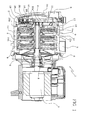
- Figure 1 is a longitudinal section of the centrifugal pump in accordance with the invention;
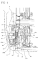
- Figure 2 is a view of a construction detail of the pump illustrated in Figure 1 in a first operating condition;
- Figure 3 is a view of a construction detail of the pump illustrated in Figure 1 in a second operating condition;
- Figure 4 is a view of a construction detail of the pump illustrated in Figure 1 in a third operating condition;
- Figure 5 is an exploded perspective view of part of the centrifugal pump in accordance with the invention.
- With reference to the accompanying drawings, the
numeral 1 denotes as a whole the centrifugal pump in accordance with the invention. - As Figure 1 shows, the
pump 1 has acontainment body 2 with mainly cylindrical extension, having afirst end 2a which extends transversally to the longitudinal extension of thecontainment body 2. Thefirst end 2a has ahole 3 which is part of an infeedpipe 4 for the water sucked in by the pump. - It should be noticed that this description refers specifically to a
centrifugal pump 1 suitable for sucking up water. Such pumps are widely used in various types of hydraulic systems. However, thepump 1 may be used to suck up any other type of fluid in the liquid state. - The
containment body 2 also has a side surface in which there is ahole 5, which is part of an outfeedpipe 6 for the water sucked up by thepump 1. Theholes pipe 4 and theoutfeed pipe 6 can advantageously be connected to respective pipes of a water system to which thepump 1 is connected. However, in other embodiments the twoholes - The
containment body 2 also has a second end 2b, opposite thefirst end 2a, to which the drive means 7 are connected. The drive means, illustrated only in Figure 1, preferably consist of a known type of electric motor, having arotary shaft 8 which extends along the longitudinal extension of thebody 2 and inside thebody 2. - Inside the
containment body 2 there also extends at least oneintake stage 9 consisting of at least oneimpeller 10 keyed to theshaft 8 to suck water from the infeedpipe 4 and convey it to the outfeedpipe 6. - As is better illustrated in the exploded view in Figure 5, the
pump 1 may have a plurality ofintake stages 9, consecutive and connected to one another along the longitudinal extension of thebody 2. - In detail, each
stage 9 consists of animpeller 10 and adiffuser 11, the latter coaxial with and alongside therespective impeller 10. - In particular, in the embodiment illustrated, the
impeller 10 substantially consists of two disks alongside one another and between which special blades are housed, for conveying the water in rotation from a centralwater passage zone 10a to a peripheraloutfeed zone 10b. Thediffuser 11 consists of a ring-shaped deflector 11a coaxially inserted, with the relative impeller, in atubular body 11b. Thedeflector 11a is designed to convey the water out of theperipheral zone 10b of theimpeller 10 and towards thecentral zone 10a of thenext stage 9. Thetubular bodies 11b are alongside one another in such a way that they form a closedcylindrical body 12. - In other words, the
tubular bodies 11b are coaxially connected to one another to form a singlecylindrical body 12 located in thecontainment body 2 and housing theimpellers 10. - As illustrated in the exploded view in Figure 5, the
pump 1 also has a connectingcollar 13, inside thebody 2 at the infeedpipe 4hole 3. - In particular, the
collar 13 substantially consists of a ring-shaped element which can be connected between thestage 9 next to the infeedpipe 4 and the inner surface of the body 2 (see Figure 1). Moreover, thepump 1 has anend diffuser 14, connected to thestage 9 next to theoutfeed pipe 6 and having a set of deflectors suitable for eliminating any water turbulence at the outfeed of theimpeller 10 closest to theoutfeed pipe 6. Moreover, theend diffuser 14 has an axial fluid infeed hole and radial outfeed holes. - As is better illustrated in Figure 1, the
cylindrical body 12 is detached from the inner surface of thecontainment body 2 to form both theoutfeed pipe 6 and anauxiliary pipe 15. - In greater detail, in the embodiment illustrated, the
auxiliary pipe 15 extends inside thepump 1 from theoutfeed pipe 6 towards the infeedpipe 4. In even more detail, theauxiliary pipe 15 has a substantially cylindrical shape surrounding thecylindrical body 12 and forms afirst end 15a at the connectingcollar 13, and asecond end 15b opposite thefirst end 15a, located at theoutfeed pipe 6. - The
pump 1 also comprises arecirculation part 16 inserted between theoutfeed pipe 6 and the infeedpipe 4 to allow the passage of water from theoutfeed pipe 6 to the infeedpipe 4 in an initial pump starting step. - In particular, the
recirculation part 16 is located at thefirst end 15a of theauxiliary pipe 15, next to acentral zone 10a of theimpeller 10 near theinfeed pipe 4. - In detail, the
recirculation part 16 has a primary self-priming valve 17 which can be switched between an open condition in which it allows water to pass from theauxiliary pipe 15 to the infeed pipe 4 (see Figure 3), and a closed position in which it blocks theauxiliary pipe 15 and prevents the passage of water (see Figures 2 and 4). - In particular, the
recirculation part 16 comprises a connectingplate 18 located between the infeed pipe and the auxiliary pipe. Theplate 18 advantageously engages with thecollar 13 and substantially has the shape of a parallelepiped. Theprimary valve 17 is housed in an opening 18a made in the plate, forming the section which allows the passage of water when theprimary valve 17 is open. - There are also
primary valve 17 locking means 26, to keep thevalve 17 open until the pressure of the fluid in the outfeedpipe 6 exceeds a predetermined pressure value corresponding to pump steady state operation (transient operation during self-priming). - The
pump 1 also comprises asafety valve 19 which can switch between an open condition in which it allows water to pass from the outfeedpipe 6 to the infeed pipe 4 (Figure 4), and a closed condition in which it does not allow the passage of water (Figures 2 and 3). - Again, there are
safety valve 19 locking means 26 to keep thevalve 19 closed until the pressure of the fluid in the outfeedpipe 6 exceeds a predetermined pressure value P corresponding to the maximum delivery pressure value allowed. - Advantageously, the
safety valve 19 is connected to therecirculation part 16 and in particular is alongside theprimary valve 17. When the pressure of the water in theauxiliary pipe 15 is greater than a predetermined pressure value P, thevalve 19 is switched to the open condition. - In particular, the
safety valve 19 is also housed in anopening 18b made in theplate 18 and forming the section which allows the passage of water when thesafety valve 19 is open. Therefore, in the embodiment illustrated, the twoopenings infeed pipe 4. - As is better illustrated in Figures 2 - 4, each
valve cylindrical portion 20 which slides in therespective opening 18afirst end 20a located towards theauxiliary pipe 15 and asecond end 20b opposite thefirst end 20a located at theinfeed pipe 4. - Each
valve head 21 connected to the respectivefirst end 20a. Thehead 21 is diskshaped, extending flat transversally to the longitudinal extension of thecylindrical portion 20. It should be noticed that thehead 20 may be inserted in theopening respective valve valve head 21 is detached from theopening - In further detail, it should be noticed that the
head 21 in thevalve opening head 21 has a special O-ring 21a in contact with the narrowing and guaranteeing the valve hydraulic seal. - It should also be noticed that the narrowing of the
opening 18a housing theprimary valve 17 is achieved in the part towards theinfeed pipe 4. In this way, when theprimary valve 17 is open, the head is moved towards the auxiliary pipe 15 (see Figure 3). - The narrowing of the
opening 18b housing thesafety valve 19 is achieved in the part towards theauxiliary pipe 15. In this way, when thesafety valve 19 is open, thehead 21 is moved towards the infeed pipe 4 (see Figure 4). - Moreover, the
recirculation part 16 has a supportingelement 22 connected to theplate 18 and having respective slidingseats 23 housing the second ends 20b of eachcylindrical portion 20. - In particular, the supporting
element 22 consists of a flat element connected to theplate 18 and detached from it to form apassage 24 for the water from theopenings infeed pipe 4. - In greater detail, in the accompanying drawings the supporting
element 22 is housed in theinfeed pipe 4 and is connected to theplate 18 by respective peripheral edges which can engage with one another to form a box-shapedbody 25 in which thepassage 24 for the water is made. - Returning to the
elastic element 26a connected to eachvalve cylindrical portion 20 and having a first end 26b connected to the supportingelement 22 and a second end 26c opposite the first end 26b, connected to therespective head 21 to push therelative valve opening elastic element 26a connected to theprimary valve 17 pushes thevalve 17 towards the open condition. In other words, theelastic element 26a pushes thehead 21 of theprimary valve 17 towards theauxiliary pipe 15 outside theopening 18a. - The
elastic element 26a connected to thesafety valve 19 pushes thehead 21 towards the narrowing in theopening 18b, keeping thesafety valve 19 closed. -
Pump 1 operation, described mainly in structural terms, is as follows. - The drive means 7 cause the
impellers 10 to rotate which, as described above, suck the water from theinfeed pipe 4 and convey it towards theoutfeed pipe 6. Duringpump 1 steady state operation part of the water flowing out of thepipe 6 also passes through theauxiliary pipe 15. During this operating step both of thevalves auxiliary pipe 15 to the infeed pipe 4 (Figure 2) . - Advantageously, if the water pressure in the
outfeed pipe 6 and as a result in theauxiliary pipe 15 goes above a predetermined pressure value P, thesafety valve 19 switches, overcoming the resistance of theelastic element 26a, to the open position, allowing water to pass from thedelivery pipe 6 to the infeed pipe 4 (Figure 4). It should be noticed that the pressurised water in theauxiliary pipe 15 pushes against thehead 21 of thesafety valve 19. Theelastic element 26a of thesafety valve 19 keeps the valve locked in the closed condition. If the water pressure increases, the action of theelastic element 26a is overcome and thehead 21 of thevalve 19 is moved out of theopening 18b, allowing water to pass through theopening 18b, thus returning the water to theinfeed pipe 4. In this way, thesafety valve 19 is opened when the pressure of the water flowing out rises above the limit value P. As a result, said pressure is always kept below a predetermined pressure value P. - It should also be noticed that during
pump 1 operation, the water pressure in theauxiliary pipe 15 keeps the primary self-primingvalve 17 closed, because the action of the counteractingelement 26a is overcome by the water pressure. - When the drive mans 7 are stopped and the impellers no longer suck in water, the residual water pressure in the
outfeed pipe 6 and in theauxiliary pipe 15 falls. In this situation, the counteractingelement 26a connected to theprimary valve 17 pushes thevalve 17 into the open position, allowing the residual water in theauxiliary pipe 15 to enter theprimary pipe 4. - Advantageously, when the
pump 1 is started up again, the impellers suck in the water returned into circulation by theprimary valve 17 until the pressure in theauxiliary pipe 15 again pushes thevalve 17 into the closed position (as happens when the pump is primed with a consequent absence of air in the intake pipe). - The invention brings important advantages.
- It should be noticed that, if the pressure in the
pump 1 increases above the predetermined pressure value P, thesafety valve 19 allows the water delivered to be recirculated, re-establishing an optimum pressure value. - Advantageously, it should be noticed that the
safety valve 19 returns the water into circulation in theinfeed pipe 4, preventing the water from flowing out of thepump 1body 2, unlike the safety devices known today which discharge the water to the outside of the system delivery pipe. The solution provided by the present invention is also advantageous compared with solutions involving the creation of a by-pass outside the pump, since such solutions are significantly more expensive and bulky. - It should also be noticed that the pressure value P which causes the
safety valve 19 to open may be set by acting on the counteractingelement 26. In other words, the physical characteristics of the counteracting element 26 (number of coils, spring cross-section) can be used to define the value P above which the spring allows water to pass towards theinfeed pipe 4. - Another advantage of the present invention is that both
valves body 25 inserted in the pump, thus limiting thepump 1 overall dimensions. Both theprimary valve 17 which allows pump self-priming, and thesafety valve 19 for maintaining the predetermined pressure value P are connected to the box-shapedbody 25. Advantageously, any maintenance work on both valves may be carried out by simply substituting only the box-shapedbody 25.
Claims (15)
- A centrifugal pump, comprising:- a containment body (2) with an infeed pipe (4) and an outfeed pipe (6);- at least one intake stage (9) located in the containment body (2) between the pipes (4, 6), and having at least one impeller (10) for sucking a fluid from the infeed pipe (4) and conveying it towards the outfeed pipe (6);- drive means (7) for the impeller (10);the pump being characterised in that it also comprises a safety valve (19) located in the containment body (2) and able to switch between an open condition in which it allows fluid to pass from the outfeed pipe (6) to the infeed pipe (4), and a closed condition in which it does not allow the passage of the fluid; and safety valve (19) locking means (26) for keeping the valve (19) closed until the pressure of the fluid in the outfeed pipe (6) exceeds a predetermined pressure value P.
- The pump according to the foregoing claim, also comprising a recirculation part (16) inserted between the outfeed pipe (6) and the infeed pipe (4), allowing fluid to pass from the outfeed pipe (6) to the infeed pipe (4); the safety valve (19) being part of the recirculation part (16).
- The pump according to either of the foregoing claims, also comprising an auxiliary pipe (15) in fluid communication with the outfeed pipe (6), the recirculation part (16) being inserted between the auxiliary pipe (15) and the infeed pipe (4).
- The pump according to claim 2 or 3 when dependent on 2, characterised in that the recirculation part (16) comprises a primary valve (17) that can switch between an open condition in which it allows fluid to pass from the outfeed pipe (6) to the infeed pipe (4) and a closed condition in which it does not allow the passage of fluid; and primary valve (17) locking means (26) for keeping the valve (17) open until the pressure of the fluid in the outfeed pipe (6) is lower than a predetermined pressure value.
- The pump according to the foregoing claim, characterised in that the recirculation part (16) also comprises a connecting plate (18) located between the infeed pipe (4) and the outfeed pipe (6); the primary valve (17) and the safety valve (19) being housed in respective openings (18a, 18b) made in the plate (18) forming sections for the passage of the fluid in the valve (17, 19) open condition.
- The pump according to the foregoing claim, characterised in that each valve (17, 19) has a cylindrical portion (20) which slides in the respective opening (18a, 18b), and a head (21) connected to a first end (20a) of the cylindrical portion (20) and extending transversally to the longitudinal extension of the cylindrical portion (20); the head (21) in the closed position blocking the opening (18a, 18b), and in the open position being detached from the respective opening (18a, 18b).
- The pump according to the foregoing claim, characterised in that the recirculation part (16) also comprises a supporting element (22) connected to the plate (18) and having respective sliding seats (23) for a second end (20b) of each cylindrical portion (20) opposite the first end (20a); the supporting element (22) being detached from the plate (18) to form a passage (24) for the fluid from the openings (18) to the infeed pipe (4).
- The pump according to claim 7, characterised in that the supporting element (22) and the plate (18) have respective peripheral edges which can be connected to one another to form a box-shaped body (25) in which the passage (24) for the fluid is created.
- The pump according to any of the claims from 4 to 8, characterised in that the primary valve (17) locking means (26) comprise an elastic counteracting element (26a) connected to the valve (17).
- The pump according to any of the foregoing claims, characterised in that the safety valve (19) locking means (26) comprise an elastic counteracting element (26a) connected to the valve (19).
- The pump according to claim 9 or 10, characterised in that the elastic element (26a) comprises a helical spring fitted to the respective cylindrical portion (20).
- The pump according to claims 9 and 10, or 9, 10 and 11, characterised in that the elastic element (26a) connected to the primary valve (17) has a first end (26b) connected to the supporting element (22) and a second end (26c), opposite the first end (26b), connected to the respective head (21) for pushing the valve (17) into the open condition; and also being characterised in that the elastic element (26a) connected to the safety valve (19) has a first end (26b) connected to the supporting element (22) and a second end (26c), opposite the first end (26b), connected to the respective head (21) for pushing the valve (19) into the closed condition.
- The pump according to any of the foregoing claims, comprising a plurality of intake stages (9); each stage (9) also having a diffuser (11), coaxial with and downstream alongside the respective impeller (10).
- The pump according to the foregoing claim, characterised in that each diffuser (11) is connected to an impeller (10) for conveying the fluid out of a peripheral outfeed portion (10b) of the impeller (10) towards a central infeed portion (10a) of a subsequent stage (9).
- The pump according to claims 3 and 13, characterised in that the stages (9) are alongside one another, forming a closed cylindrical body (12) housed in the containment body (2); the auxiliary pipe (15) being between the cylindrical body (12) and the containment body (2).
Priority Applications (3)
| Application Number | Priority Date | Filing Date | Title |
|---|---|---|---|
| AT05425397T ATE366878T1 (en) | 2005-05-31 | 2005-05-31 | CENTRIFUGAL PUMP |
| DE602005001620T DE602005001620D1 (en) | 2005-05-31 | 2005-05-31 | rotary pump |
| EP05425397A EP1729009B1 (en) | 2005-05-31 | 2005-05-31 | Centrifugal pump |
Applications Claiming Priority (1)
| Application Number | Priority Date | Filing Date | Title |
|---|---|---|---|
| EP05425397A EP1729009B1 (en) | 2005-05-31 | 2005-05-31 | Centrifugal pump |
Publications (2)
| Publication Number | Publication Date |
|---|---|
| EP1729009A1 true EP1729009A1 (en) | 2006-12-06 |
| EP1729009B1 EP1729009B1 (en) | 2007-07-11 |
Family
ID=34943213
Family Applications (1)
| Application Number | Title | Priority Date | Filing Date |
|---|---|---|---|
| EP05425397A Active EP1729009B1 (en) | 2005-05-31 | 2005-05-31 | Centrifugal pump |
Country Status (3)
| Country | Link |
|---|---|
| EP (1) | EP1729009B1 (en) |
| AT (1) | ATE366878T1 (en) |
| DE (1) | DE602005001620D1 (en) |
Cited By (3)
| Publication number | Priority date | Publication date | Assignee | Title |
|---|---|---|---|---|
| US20120251308A1 (en) * | 2011-03-29 | 2012-10-04 | Grundfos Management A/S | Multi-stage centrifugal pump unit |
| EP3929445A1 (en) * | 2020-06-22 | 2021-12-29 | Grundfos Holding A/S | Centrifugal pump device |
| EP4191065A1 (en) * | 2021-12-02 | 2023-06-07 | Husqvarna Ab | Watering pump |
Families Citing this family (1)
| Publication number | Priority date | Publication date | Assignee | Title |
|---|---|---|---|---|
| EP3244066B1 (en) | 2016-05-12 | 2020-11-18 | Grundfos Holding A/S | Centrifugal pump |
Citations (4)
| Publication number | Priority date | Publication date | Assignee | Title |
|---|---|---|---|---|
| DE1913242A1 (en) * | 1969-03-15 | 1970-09-24 | Wilfried Niemes | Device for keeping the delivery height of centrifugal pumps constant with a variable delivery rate |
| DE2106852A1 (en) * | 1971-02-13 | 1972-09-14 | Sueddeutsche Kuehler Behr | Heating circulation pump |
| WO1993011360A1 (en) * | 1991-12-05 | 1993-06-10 | Nocchi Pompe S.P.A. | Centrifugal pump with adaptor for various valves |
| DE19709484A1 (en) * | 1997-03-07 | 1998-09-10 | Hella Kg Hueck & Co | Unit for regulating coolant temperature of internal combustion engine in motor vehicle |
-
2005
- 2005-05-31 EP EP05425397A patent/EP1729009B1/en active Active
- 2005-05-31 DE DE602005001620T patent/DE602005001620D1/en active Active
- 2005-05-31 AT AT05425397T patent/ATE366878T1/en not_active IP Right Cessation
Patent Citations (4)
| Publication number | Priority date | Publication date | Assignee | Title |
|---|---|---|---|---|
| DE1913242A1 (en) * | 1969-03-15 | 1970-09-24 | Wilfried Niemes | Device for keeping the delivery height of centrifugal pumps constant with a variable delivery rate |
| DE2106852A1 (en) * | 1971-02-13 | 1972-09-14 | Sueddeutsche Kuehler Behr | Heating circulation pump |
| WO1993011360A1 (en) * | 1991-12-05 | 1993-06-10 | Nocchi Pompe S.P.A. | Centrifugal pump with adaptor for various valves |
| DE19709484A1 (en) * | 1997-03-07 | 1998-09-10 | Hella Kg Hueck & Co | Unit for regulating coolant temperature of internal combustion engine in motor vehicle |
Cited By (10)
| Publication number | Priority date | Publication date | Assignee | Title |
|---|---|---|---|---|
| US20120251308A1 (en) * | 2011-03-29 | 2012-10-04 | Grundfos Management A/S | Multi-stage centrifugal pump unit |
| CN102734176A (en) * | 2011-03-29 | 2012-10-17 | 格伦德福斯管理联合股份公司 | Multi stage centrifugal pump system |
| AU2012201654B2 (en) * | 2011-03-29 | 2015-08-20 | Grundfos Management A/S | Centrifugal radial pumps and method for manufacturing thereof |
| US9879680B2 (en) * | 2011-03-29 | 2018-01-30 | Grundfos Management A/S | Multi-stage centrifugal pump unit |
| EP2505842B1 (en) | 2011-03-29 | 2019-12-25 | Grundfos Management a/s | Multi stage centrifugal pump system |
| EP3929445A1 (en) * | 2020-06-22 | 2021-12-29 | Grundfos Holding A/S | Centrifugal pump device |
| CN113898591A (en) * | 2020-06-22 | 2022-01-07 | 格兰富控股联合股份公司 | Centrifugal pump device |
| US11746795B2 (en) | 2020-06-22 | 2023-09-05 | Grundfos Holding A/S | Centrifugal pump device |
| CN113898591B (en) * | 2020-06-22 | 2024-03-01 | 格兰富控股联合股份公司 | Centrifugal pump device |
| EP4191065A1 (en) * | 2021-12-02 | 2023-06-07 | Husqvarna Ab | Watering pump |
Also Published As
| Publication number | Publication date |
|---|---|
| DE602005001620D1 (en) | 2007-08-23 |
| ATE366878T1 (en) | 2007-08-15 |
| EP1729009B1 (en) | 2007-07-11 |
Similar Documents
| Publication | Publication Date | Title |
|---|---|---|
| EP1729009B1 (en) | Centrifugal pump | |
| AU2014270689B2 (en) | Multistage self-suctioning centrifugal pump unit | |
| US7121786B2 (en) | Mix-in structure for gas or the like in pressurization centrifugal pump | |
| GB2369071A (en) | Pump device | |
| US6264434B1 (en) | Air pressure driven two way fluid evacuation and expulsion system | |
| US11053940B2 (en) | Vacuum pump with separate oil outlet with relief valve | |
| KR100841958B1 (en) | Pump that have cavitation prevention function | |
| KR200399161Y1 (en) | Fish pump | |
| US5993151A (en) | Centrifugal pump device | |
| US20120207590A1 (en) | Anti-airlock pump | |
| US11808265B2 (en) | Energy-conserving fluid pump | |
| EP2958679B1 (en) | Pressure relief module | |
| EP3850219B1 (en) | Self-priming centrifugal pump | |
| ES2225244T3 (en) | GROUP MOTORCYCLE-COMPACT PUMP. | |
| CN110073113B (en) | Vortex pump | |
| US20240026903A1 (en) | Energy-conserving fluid pump | |
| US4494560A (en) | Self-priming system for liquid pumps | |
| WO2005010374A1 (en) | Self-priming centrifugal pump | |
| KR100545834B1 (en) | A centrifugal pump | |
| KR960016040B1 (en) | Pump | |
| CN107906016A (en) | One kind is without sealing self-controlling self-priming pump | |
| RU2205985C2 (en) | Portable drainage turbopump | |
| KR100371418B1 (en) | the vacuum pump for mixing liquid and gas | |
| JP6491305B1 (en) | Two-stage variable oil pump | |
| JPS644741Y2 (en) |
Legal Events
| Date | Code | Title | Description |
|---|---|---|---|
| PUAI | Public reference made under article 153(3) epc to a published international application that has entered the european phase |
Free format text: ORIGINAL CODE: 0009012 |
|
| 17P | Request for examination filed |
Effective date: 20060428 |
|
| AK | Designated contracting states |
Kind code of ref document: A1 Designated state(s): AT BE BG CH CY CZ DE DK EE ES FI FR GB GR HU IE IS IT LI LT LU MC NL PL PT RO SE SI SK TR |
|
| AX | Request for extension of the european patent |
Extension state: AL BA HR LV MK YU |
|
| GRAP | Despatch of communication of intention to grant a patent |
Free format text: ORIGINAL CODE: EPIDOSNIGR1 |
|
| GRAS | Grant fee paid |
Free format text: ORIGINAL CODE: EPIDOSNIGR3 |
|
| GRAA | (expected) grant |
Free format text: ORIGINAL CODE: 0009210 |
|
| AK | Designated contracting states |
Kind code of ref document: B1 Designated state(s): AT BE BG CH CY CZ DE DK EE ES FI FR GB GR HU IE IS IT LI LT LU MC NL PL PT RO SE SI SK TR |
|
| AX | Request for extension of the european patent |
Extension state: AL BA HR LV MK YU |
|
| REG | Reference to a national code |
Ref country code: GB Ref legal event code: FG4D |
|
| REG | Reference to a national code |
Ref country code: CH Ref legal event code: EP |
|
| AKX | Designation fees paid |
Designated state(s): AT BE BG CH CY CZ DE DK EE ES FI FR GB GR HU IE IS IT LI LT LU MC NL PL PT RO SE SI SK TR |
|
| AXX | Extension fees paid |
Extension state: MK Payment date: 20061220 Extension state: AL Payment date: 20061220 Extension state: BA Payment date: 20061220 Extension state: LV Payment date: 20061220 Extension state: YU Payment date: 20061220 Extension state: HR Payment date: 20061220 |
|
| REF | Corresponds to: |
Ref document number: 602005001620 Country of ref document: DE Date of ref document: 20070823 Kind code of ref document: P |
|
| REG | Reference to a national code |
Ref country code: IE Ref legal event code: FG4D |
|
| PG25 | Lapsed in a contracting state [announced via postgrant information from national office to epo] |
Ref country code: NL Free format text: LAPSE BECAUSE OF FAILURE TO SUBMIT A TRANSLATION OF THE DESCRIPTION OR TO PAY THE FEE WITHIN THE PRESCRIBED TIME-LIMIT Effective date: 20070711 Ref country code: IS Free format text: LAPSE BECAUSE OF FAILURE TO SUBMIT A TRANSLATION OF THE DESCRIPTION OR TO PAY THE FEE WITHIN THE PRESCRIBED TIME-LIMIT Effective date: 20071111 Ref country code: LT Free format text: LAPSE BECAUSE OF FAILURE TO SUBMIT A TRANSLATION OF THE DESCRIPTION OR TO PAY THE FEE WITHIN THE PRESCRIBED TIME-LIMIT Effective date: 20070711 Ref country code: PT Free format text: LAPSE BECAUSE OF FAILURE TO SUBMIT A TRANSLATION OF THE DESCRIPTION OR TO PAY THE FEE WITHIN THE PRESCRIBED TIME-LIMIT Effective date: 20071211 Ref country code: BG Free format text: LAPSE BECAUSE OF FAILURE TO SUBMIT A TRANSLATION OF THE DESCRIPTION OR TO PAY THE FEE WITHIN THE PRESCRIBED TIME-LIMIT Effective date: 20071011 Ref country code: FI Free format text: LAPSE BECAUSE OF FAILURE TO SUBMIT A TRANSLATION OF THE DESCRIPTION OR TO PAY THE FEE WITHIN THE PRESCRIBED TIME-LIMIT Effective date: 20070711 Ref country code: ES Free format text: LAPSE BECAUSE OF FAILURE TO SUBMIT A TRANSLATION OF THE DESCRIPTION OR TO PAY THE FEE WITHIN THE PRESCRIBED TIME-LIMIT Effective date: 20071022 |
|
| REG | Reference to a national code |
Ref country code: CH Ref legal event code: PL |
|
| NLV1 | Nl: lapsed or annulled due to failure to fulfill the requirements of art. 29p and 29m of the patents act | ||
| PG25 | Lapsed in a contracting state [announced via postgrant information from national office to epo] |
Ref country code: CH Free format text: LAPSE BECAUSE OF FAILURE TO SUBMIT A TRANSLATION OF THE DESCRIPTION OR TO PAY THE FEE WITHIN THE PRESCRIBED TIME-LIMIT Effective date: 20070711 Ref country code: AT Free format text: LAPSE BECAUSE OF FAILURE TO SUBMIT A TRANSLATION OF THE DESCRIPTION OR TO PAY THE FEE WITHIN THE PRESCRIBED TIME-LIMIT Effective date: 20070711 Ref country code: LI Free format text: LAPSE BECAUSE OF FAILURE TO SUBMIT A TRANSLATION OF THE DESCRIPTION OR TO PAY THE FEE WITHIN THE PRESCRIBED TIME-LIMIT Effective date: 20070711 Ref country code: PL Free format text: LAPSE BECAUSE OF FAILURE TO SUBMIT A TRANSLATION OF THE DESCRIPTION OR TO PAY THE FEE WITHIN THE PRESCRIBED TIME-LIMIT Effective date: 20070711 |
|
| EN | Fr: translation not filed | ||
| PG25 | Lapsed in a contracting state [announced via postgrant information from national office to epo] |
Ref country code: BE Free format text: LAPSE BECAUSE OF FAILURE TO SUBMIT A TRANSLATION OF THE DESCRIPTION OR TO PAY THE FEE WITHIN THE PRESCRIBED TIME-LIMIT Effective date: 20070711 |
|
| PG25 | Lapsed in a contracting state [announced via postgrant information from national office to epo] |
Ref country code: DK Free format text: LAPSE BECAUSE OF FAILURE TO SUBMIT A TRANSLATION OF THE DESCRIPTION OR TO PAY THE FEE WITHIN THE PRESCRIBED TIME-LIMIT Effective date: 20070711 Ref country code: GR Free format text: LAPSE BECAUSE OF FAILURE TO SUBMIT A TRANSLATION OF THE DESCRIPTION OR TO PAY THE FEE WITHIN THE PRESCRIBED TIME-LIMIT Effective date: 20071012 |
|
| PLBE | No opposition filed within time limit |
Free format text: ORIGINAL CODE: 0009261 |
|
| STAA | Information on the status of an ep patent application or granted ep patent |
Free format text: STATUS: NO OPPOSITION FILED WITHIN TIME LIMIT |
|
| PG25 | Lapsed in a contracting state [announced via postgrant information from national office to epo] |
Ref country code: SK Free format text: LAPSE BECAUSE OF FAILURE TO SUBMIT A TRANSLATION OF THE DESCRIPTION OR TO PAY THE FEE WITHIN THE PRESCRIBED TIME-LIMIT Effective date: 20070711 Ref country code: CZ Free format text: LAPSE BECAUSE OF FAILURE TO SUBMIT A TRANSLATION OF THE DESCRIPTION OR TO PAY THE FEE WITHIN THE PRESCRIBED TIME-LIMIT Effective date: 20070711 |
|
| 26N | No opposition filed |
Effective date: 20080414 |
|
| PG25 | Lapsed in a contracting state [announced via postgrant information from national office to epo] |
Ref country code: SE Free format text: LAPSE BECAUSE OF FAILURE TO SUBMIT A TRANSLATION OF THE DESCRIPTION OR TO PAY THE FEE WITHIN THE PRESCRIBED TIME-LIMIT Effective date: 20071011 Ref country code: RO Free format text: LAPSE BECAUSE OF FAILURE TO SUBMIT A TRANSLATION OF THE DESCRIPTION OR TO PAY THE FEE WITHIN THE PRESCRIBED TIME-LIMIT Effective date: 20070711 |
|
| PG25 | Lapsed in a contracting state [announced via postgrant information from national office to epo] |
Ref country code: FR Free format text: LAPSE BECAUSE OF FAILURE TO SUBMIT A TRANSLATION OF THE DESCRIPTION OR TO PAY THE FEE WITHIN THE PRESCRIBED TIME-LIMIT Effective date: 20080307 Ref country code: DE Free format text: LAPSE BECAUSE OF FAILURE TO SUBMIT A TRANSLATION OF THE DESCRIPTION OR TO PAY THE FEE WITHIN THE PRESCRIBED TIME-LIMIT Effective date: 20071012 |
|
| PG25 | Lapsed in a contracting state [announced via postgrant information from national office to epo] |
Ref country code: MC Free format text: LAPSE BECAUSE OF NON-PAYMENT OF DUE FEES Effective date: 20080531 |
|
| PGFP | Annual fee paid to national office [announced via postgrant information from national office to epo] |
Ref country code: IE Payment date: 20081219 Year of fee payment: 4 |
|
| PG25 | Lapsed in a contracting state [announced via postgrant information from national office to epo] |
Ref country code: EE Free format text: LAPSE BECAUSE OF FAILURE TO SUBMIT A TRANSLATION OF THE DESCRIPTION OR TO PAY THE FEE WITHIN THE PRESCRIBED TIME-LIMIT Effective date: 20070711 |
|
| PG25 | Lapsed in a contracting state [announced via postgrant information from national office to epo] |
Ref country code: SI Free format text: LAPSE BECAUSE OF FAILURE TO SUBMIT A TRANSLATION OF THE DESCRIPTION OR TO PAY THE FEE WITHIN THE PRESCRIBED TIME-LIMIT Effective date: 20070711 |
|
| PG25 | Lapsed in a contracting state [announced via postgrant information from national office to epo] |
Ref country code: CY Free format text: LAPSE BECAUSE OF FAILURE TO SUBMIT A TRANSLATION OF THE DESCRIPTION OR TO PAY THE FEE WITHIN THE PRESCRIBED TIME-LIMIT Effective date: 20070711 |
|
| GBPC | Gb: european patent ceased through non-payment of renewal fee |
Effective date: 20090531 |
|
| PG25 | Lapsed in a contracting state [announced via postgrant information from national office to epo] |
Ref country code: IE Free format text: LAPSE BECAUSE OF NON-PAYMENT OF DUE FEES Effective date: 20090531 |
|
| PG25 | Lapsed in a contracting state [announced via postgrant information from national office to epo] |
Ref country code: GB Free format text: LAPSE BECAUSE OF NON-PAYMENT OF DUE FEES Effective date: 20090531 |
|
| PG25 | Lapsed in a contracting state [announced via postgrant information from national office to epo] |
Ref country code: LU Free format text: LAPSE BECAUSE OF NON-PAYMENT OF DUE FEES Effective date: 20080531 Ref country code: HU Free format text: LAPSE BECAUSE OF FAILURE TO SUBMIT A TRANSLATION OF THE DESCRIPTION OR TO PAY THE FEE WITHIN THE PRESCRIBED TIME-LIMIT Effective date: 20080112 |
|
| PG25 | Lapsed in a contracting state [announced via postgrant information from national office to epo] |
Ref country code: TR Free format text: LAPSE BECAUSE OF FAILURE TO SUBMIT A TRANSLATION OF THE DESCRIPTION OR TO PAY THE FEE WITHIN THE PRESCRIBED TIME-LIMIT Effective date: 20070711 |
|
| PGFP | Annual fee paid to national office [announced via postgrant information from national office to epo] |
Ref country code: IT Payment date: 20130529 Year of fee payment: 9 |
|
| PG25 | Lapsed in a contracting state [announced via postgrant information from national office to epo] |
Ref country code: IT Free format text: LAPSE BECAUSE OF NON-PAYMENT OF DUE FEES Effective date: 20140531 |