EP1728980A1 - Engine comprising multiple cylinders - Google Patents
Engine comprising multiple cylinders Download PDFInfo
- Publication number
- EP1728980A1 EP1728980A1 EP06011113A EP06011113A EP1728980A1 EP 1728980 A1 EP1728980 A1 EP 1728980A1 EP 06011113 A EP06011113 A EP 06011113A EP 06011113 A EP06011113 A EP 06011113A EP 1728980 A1 EP1728980 A1 EP 1728980A1
- Authority
- EP
- European Patent Office
- Prior art keywords
- control
- swing
- valve
- cam
- cylinder groups
- Prior art date
- Legal status (The legal status is an assumption and is not a legal conclusion. Google has not performed a legal analysis and makes no representation as to the accuracy of the status listed.)
- Granted
Links
- 230000008859 change Effects 0.000 claims abstract description 61
- 230000007246 mechanism Effects 0.000 claims abstract description 36
- 230000005540 biological transmission Effects 0.000 claims abstract description 18
- 238000013459 approach Methods 0.000 claims description 8
- 238000004519 manufacturing process Methods 0.000 description 9
- 210000001331 nose Anatomy 0.000 description 6
- 230000035939 shock Effects 0.000 description 4
- 230000007423 decrease Effects 0.000 description 3
- 238000002485 combustion reaction Methods 0.000 description 2
- 238000010586 diagram Methods 0.000 description 2
- 230000000694 effects Effects 0.000 description 2
- 239000000725 suspension Substances 0.000 description 2
- 230000003247 decreasing effect Effects 0.000 description 1
- 239000000446 fuel Substances 0.000 description 1
- 210000003128 head Anatomy 0.000 description 1
Images




Classifications
-
- F—MECHANICAL ENGINEERING; LIGHTING; HEATING; WEAPONS; BLASTING
- F01—MACHINES OR ENGINES IN GENERAL; ENGINE PLANTS IN GENERAL; STEAM ENGINES
- F01L—CYCLICALLY OPERATING VALVES FOR MACHINES OR ENGINES
- F01L13/00—Modifications of valve-gear to facilitate reversing, braking, starting, changing compression ratio, or other specific operations
- F01L13/0015—Modifications of valve-gear to facilitate reversing, braking, starting, changing compression ratio, or other specific operations for optimising engine performances by modifying valve lift according to various working parameters, e.g. rotational speed, load, torque
- F01L13/0063—Modifications of valve-gear to facilitate reversing, braking, starting, changing compression ratio, or other specific operations for optimising engine performances by modifying valve lift according to various working parameters, e.g. rotational speed, load, torque by modification of cam contact point by displacing an intermediate lever or wedge-shaped intermediate element, e.g. Tourtelot
-
- F—MECHANICAL ENGINEERING; LIGHTING; HEATING; WEAPONS; BLASTING
- F01—MACHINES OR ENGINES IN GENERAL; ENGINE PLANTS IN GENERAL; STEAM ENGINES
- F01L—CYCLICALLY OPERATING VALVES FOR MACHINES OR ENGINES
- F01L13/00—Modifications of valve-gear to facilitate reversing, braking, starting, changing compression ratio, or other specific operations
- F01L13/0005—Deactivating valves
-
- F—MECHANICAL ENGINEERING; LIGHTING; HEATING; WEAPONS; BLASTING
- F02—COMBUSTION ENGINES; HOT-GAS OR COMBUSTION-PRODUCT ENGINE PLANTS
- F02D—CONTROLLING COMBUSTION ENGINES
- F02D13/00—Controlling the engine output power by varying inlet or exhaust valve operating characteristics, e.g. timing
- F02D13/02—Controlling the engine output power by varying inlet or exhaust valve operating characteristics, e.g. timing during engine operation
- F02D13/06—Cutting-out cylinders
-
- F—MECHANICAL ENGINEERING; LIGHTING; HEATING; WEAPONS; BLASTING
- F01—MACHINES OR ENGINES IN GENERAL; ENGINE PLANTS IN GENERAL; STEAM ENGINES
- F01L—CYCLICALLY OPERATING VALVES FOR MACHINES OR ENGINES
- F01L13/00—Modifications of valve-gear to facilitate reversing, braking, starting, changing compression ratio, or other specific operations
- F01L13/0005—Deactivating valves
- F01L2013/001—Deactivating cylinders
-
- F—MECHANICAL ENGINEERING; LIGHTING; HEATING; WEAPONS; BLASTING
- F01—MACHINES OR ENGINES IN GENERAL; ENGINE PLANTS IN GENERAL; STEAM ENGINES
- F01L—CYCLICALLY OPERATING VALVES FOR MACHINES OR ENGINES
- F01L13/00—Modifications of valve-gear to facilitate reversing, braking, starting, changing compression ratio, or other specific operations
- F01L13/0015—Modifications of valve-gear to facilitate reversing, braking, starting, changing compression ratio, or other specific operations for optimising engine performances by modifying valve lift according to various working parameters, e.g. rotational speed, load, torque
- F01L13/0063—Modifications of valve-gear to facilitate reversing, braking, starting, changing compression ratio, or other specific operations for optimising engine performances by modifying valve lift according to various working parameters, e.g. rotational speed, load, torque by modification of cam contact point by displacing an intermediate lever or wedge-shaped intermediate element, e.g. Tourtelot
- F01L2013/0068—Modifications of valve-gear to facilitate reversing, braking, starting, changing compression ratio, or other specific operations for optimising engine performances by modifying valve lift according to various working parameters, e.g. rotational speed, load, torque by modification of cam contact point by displacing an intermediate lever or wedge-shaped intermediate element, e.g. Tourtelot with an oscillating cam acting on the valve of the "BMW-Valvetronic" type
-
- F—MECHANICAL ENGINEERING; LIGHTING; HEATING; WEAPONS; BLASTING
- F01—MACHINES OR ENGINES IN GENERAL; ENGINE PLANTS IN GENERAL; STEAM ENGINES
- F01L—CYCLICALLY OPERATING VALVES FOR MACHINES OR ENGINES
- F01L13/00—Modifications of valve-gear to facilitate reversing, braking, starting, changing compression ratio, or other specific operations
- F01L13/0015—Modifications of valve-gear to facilitate reversing, braking, starting, changing compression ratio, or other specific operations for optimising engine performances by modifying valve lift according to various working parameters, e.g. rotational speed, load, torque
- F01L13/0063—Modifications of valve-gear to facilitate reversing, braking, starting, changing compression ratio, or other specific operations for optimising engine performances by modifying valve lift according to various working parameters, e.g. rotational speed, load, torque by modification of cam contact point by displacing an intermediate lever or wedge-shaped intermediate element, e.g. Tourtelot
- F01L2013/0073—Modifications of valve-gear to facilitate reversing, braking, starting, changing compression ratio, or other specific operations for optimising engine performances by modifying valve lift according to various working parameters, e.g. rotational speed, load, torque by modification of cam contact point by displacing an intermediate lever or wedge-shaped intermediate element, e.g. Tourtelot with an oscillating cam acting on the valve of the "Delphi" type
-
- F—MECHANICAL ENGINEERING; LIGHTING; HEATING; WEAPONS; BLASTING
- F01—MACHINES OR ENGINES IN GENERAL; ENGINE PLANTS IN GENERAL; STEAM ENGINES
- F01L—CYCLICALLY OPERATING VALVES FOR MACHINES OR ENGINES
- F01L2305/00—Valve arrangements comprising rollers
-
- F—MECHANICAL ENGINEERING; LIGHTING; HEATING; WEAPONS; BLASTING
- F01—MACHINES OR ENGINES IN GENERAL; ENGINE PLANTS IN GENERAL; STEAM ENGINES
- F01L—CYCLICALLY OPERATING VALVES FOR MACHINES OR ENGINES
- F01L2800/00—Methods of operation using a variable valve timing mechanism
- F01L2800/08—Timing or lift different for valves of different cylinders
-
- Y—GENERAL TAGGING OF NEW TECHNOLOGICAL DEVELOPMENTS; GENERAL TAGGING OF CROSS-SECTIONAL TECHNOLOGIES SPANNING OVER SEVERAL SECTIONS OF THE IPC; TECHNICAL SUBJECTS COVERED BY FORMER USPC CROSS-REFERENCE ART COLLECTIONS [XRACs] AND DIGESTS
- Y02—TECHNOLOGIES OR APPLICATIONS FOR MITIGATION OR ADAPTATION AGAINST CLIMATE CHANGE
- Y02T—CLIMATE CHANGE MITIGATION TECHNOLOGIES RELATED TO TRANSPORTATION
- Y02T10/00—Road transport of goods or passengers
- Y02T10/10—Internal combustion engine [ICE] based vehicles
- Y02T10/12—Improving ICE efficiencies
-
- Y—GENERAL TAGGING OF NEW TECHNOLOGICAL DEVELOPMENTS; GENERAL TAGGING OF CROSS-SECTIONAL TECHNOLOGIES SPANNING OVER SEVERAL SECTIONS OF THE IPC; TECHNICAL SUBJECTS COVERED BY FORMER USPC CROSS-REFERENCE ART COLLECTIONS [XRACs] AND DIGESTS
- Y10—TECHNICAL SUBJECTS COVERED BY FORMER USPC
- Y10T—TECHNICAL SUBJECTS COVERED BY FORMER US CLASSIFICATION
- Y10T74/00—Machine element or mechanism
- Y10T74/21—Elements
- Y10T74/2101—Cams
- Y10T74/2107—Follower
Definitions
- the present invention relates to an engine comprising multiple cylinders, and in particular to a multi-cylinder engine, wherein an open period and a lift amount of an intake valve or an exhaust valve of each cylinder is sequentially controllable.
- a valve drive device for an engine is used, by which open periods and lift amounts of intake and exhaust valves sequentially controllable.
- this kind of valve drive device is constructed so that a camshaft drives a swing cam supported for swing movement and the swing cam actuates an intake valve or an exhaust valve between open and close positions.
- a center of the swing movement of the swing cam is variable, and an open period and a lift amount of the valve can be sequentially changed when the center of the swing movement is varied.
- JP-A-2004-316571 discloses an engine that can operate in the cylinder suspended mode and has a valve drive device by which the open period and the lift amount of respective valves are sequentially varied.
- cylinders are divided into multiple cylinder groups each having a control shaft so that valve lift, amounts are controllable every cylinder group.
- the valve lift amount of a part of cylinder groups is brought to zero in a predetermined operational range; thereby, the cylinder suspended mode operation is realized.
- the conventional engine realizing the cylinder suspended mode operation has multiple control shafts and employs a system in which the respective control shafts are controlled to have different rotational angles.
- the structure of the valve drive device is inevitably complicated and production costs thereof can increase.
- the present invention is made in view of the problems discussed above and aims to provide a multiple cylinder engine that can suspend an operation of a part of cylinders without having a complicated structure or increasing production costs.
- an engine comprising multiple cylinders being divided into multiple cylinder groups, each cylinder group comprising a change mechanism transmitting a drive force of a drive source to each of the valves of the respective cylinder group, wherein a control amount is variable to change a transmission state of the drive force of the drive source transmitted to the valves of the respective cylinder group, and wherein a valve open period and a valve lift amount of at least a first cylinder group is capable to be set to zero in a predetermined operational range to suspend an operation of said first cylinder group.
- the change mechanism is configured to sequentially change the open period and the lift amount of each valve by changing the control amount of the control member, and wherein the transmission states for the respective cylinder groups differ from each other in accordance with the control amount of the control member.
- the engine further comprises intake and exhaust valves opening and closing intake and exhaust ports of the respective cylinders, a drive shaft functioning as the drive source, and a valve actuator to which a rotational movement of the drive shaft is transmitted, the valve actuator actuating one of the valves of the respective cylinders, wherein the control amount of the control member of the change mechanism is variable to change the transmission state of the rotational movement transmitted from the drive shaft to the valve actuator, the change mechanism sequentially changing an open period and a lift amount of each valve by changing the control amount of the control member, and wherein the control member is common to the respective cylinder groups, and the transmission states for the respective cylinder groups differ from each other in accordance with the control amount of the control member, and the valve open period and the lift amount of said each valve of at least the first cylinder group are capable of being set to zero in a predetermined operational range so as to suspend an operation of the part of the cylinder groups.
- the drive shaft includes a camshaft driven by a crankshaft
- the valve actuator includes a rocker arm supported for swing movement
- the change mechanism includes a swing cam supported for swing movement to follow the camshaft
- a control arm is positioned between the swing cam and the camshaft or the rocker arm and is supported by the control member for swing movement, the control amount of the control member being varied to change a relative relationship between a position of control arm and a position of the camshaft or a position of swing cam so as to sequentially change the open period and the lift amount of the valve
- a cam surface of the swing cam has a shape which differs from each other between the cylinder groups, the cam surface of the swing cam for at least the first cylinder group being configured to bring the valve lift amount to zero when the control amount of the control member is in the predetermined range.
- control arm is positioned between the cam surface of the swing cam and the rocker arm, and wherein a relative relationship between a position of the control arm and a position of the cam surface is changed when a rotational angle of the control member is changed whereby the open period and the lift amount of said valve is sequentially controllable.
- the cam surface of the swing cam includes a base circle section and a lift section
- the base circle section is formed as a circular arc which center is consistent with a center of the swing movement of the swing cam and makes the valve lift amount zero irrespective of a swing angle of the swing cam
- the lift section increases the valve lift amount with the swing angle increasing
- the base circle section of the swing cam for the part of the cylinder groups has an angular range broader than the base circle section of the swing cam for the remainder part of the cylinder groups.
- the lift section of the swing cam for at least the first of the cylinder groups has a shape which becomes more similar to a shape of the lift section of the swing cam for the remainder part of the cylinder groups as the lift section of the swing cam for at least the first of the cylinder groups is spaced apart from a border thereof with the base circle toward the lift section.
- the drive shaft includes a camshaft driven by a crankshaft
- the valve actuator includes a rocker arm supported for swing movement
- the change mechanism includes a swing cam supported for swing movement to follow the camshaft
- a control arm is positioned between the swing cam and the camshaft or the rocker arm and is supported by the control member for swing movement
- the control amount of the control member is varied to change a relative relationship between a position of the control arm and a position of the camshaft or a position of the swing cam so as to sequentially change the open period and the lift amount of the valve
- a relative relationship between a position of the control arm and a position of the camshaft or a position of the swing cam differs from each other between the cylinder groups, the relative relationship for at least the first of the cylinder groups being determined to bring the valve lift amount to zero when the control amount of the control member is in the predetermined range.
- control arm is coupled with the control member at a position which is out of a pivot center of the control member, a deviation amount of the control arm for at least the first of the cylinder groups from the center of the control member being larger than a deviation amount of the control arm for the remainder part of the cylinder groups from the center of the control member, and wherein a contact portion at which the control arm for at least the first of the cylinder groups contacts with a cam surface retreats toward a base circle section of the cam surface more than a contact portion at which the control arm for the remainder part of cylinder groups contacts with an associated cam surface when the control member is in a predetermined angle range.
- control arm for at least the first of the cylinder groups is shorter than the control arm for the remainder part of the cylinder groups, wherein, as the control member leaves from the predetermined angle range further, the contact portion of the control arm for at least the first of the cylinder groups with the cam surface and the contact portion of the control arm for the remainder part of the cylinder groups with the cam surface approach each other closer.
- FIGs. 1 to 6 are illustrations for describing a multiple cylinder engine configured in accordance with a first embodiment.
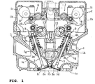
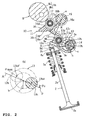
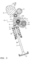
- FIGs. 1 to 3 are cross sectional, side elevational views of a valve drive device.
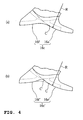
- FIG. 4 is an enlarged view of a swing cam.
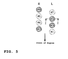
- FIG. 5 is a schematic view for describing cylinder groups.
- FIG. 6 is a characteristic diagram showing relationships between a control shaft rotational angle ⁇ and the largest lift [H].
- the engine of this embodiment is a V-type, eight cylinder engine including a left bank which has four cylinders (#1, 3, 5 and 7 of FIG. 5) and a right bank which has four cylinders (#2, 4, 6 and 8 of FIG. 5).
- the large arrow of FIG. 5 indicates a front side of the engine.
- the reference symbols R and L indicate the right bank and the left bank, respectively.
- Each right and left bank has a cylinder block, a cylinder head 1 coupled with a top end of the cylinder block and a head cover 2 detachably attached to the cylinder head 1.
- FIG. 1 is a cross sectional view taken along the line I-I of FIG. 5 (the cylinder #5 of the left bank).
- a portion of a surface 1 a of each cylinder head 1 facing the respective cylinder block is recessed to define combustion chambers 1b.
- Intake ports 1c and exhaust ports 1d open to each combustion chamber 1b.
- Each intake port 1 c and each exhaust port 1d are connected to openings defined in an inner side wall 1j of the bank and an outer side wall 1 k of the bank through an intake passage 1 e and an exhaust passage 1 f, respectively.
- a valve head 2a of an intake valve 2 and a valve head 3a of an exhaust valve 3 are positioned at each intake port 1 c and each exhaust port 1 d, respectively, to open or close the respective ports 1c, 1d.
- Valve springs 5a, 5b individually extend between retainers 4a, 4b which are attached to top ends of valve stems 2b, 3b of the respective intake valve 2 and the exhaust valve 3 and spring seats 1 g, 1 g of the cylinder head 1.
- the springs 5a, 5b urge the respective valves 2, 3 to their positions at which the valves 2, 3 close the respective ports 1 c, 1 d.
- Intake valve position sequentially changing valve drive devices 6 are individually provided for the right bank and for the left bank.
- Exhaust valve position sequentially changing valve drive devices 7 are individually provided for the right bank and for the left bank.
- An open period and a lift amount of the intake valve 2 are sequentially variable between zero and the maximum.
- an open period and a lift amount of the exhaust valve 3 are sequentially variable between zero and the maximum.
- the respective cylinders of the respective banks are divided into a suspendable cylinder group which cylinders are operated in a cylinder suspended mode in which operations of those cylinders are suspended in a low load range, and a sequentially operable cylinder group which cylinders are sequentially operated in the whole ranges. More specifically, the cylinders #1 and #7 of the left bank belong to the sequentially operable group, and the cylinders #3 and #5 of the left bank belong to the suspendable cylinder group. Also, the cylinders #2 and #8 of the right bank belong to the suspendable cylinder group, and the cylinders #4 and #6 of the right bank belong to the sequentially operable group.
- Each intake valve position sequentially changing valve drive device 6 and each exhaust valve position sequentially changing valve drive device 7 have the same structure as one another except for some portions. Therefore, mainly, the intake valve position sequentially changing valve drive device 6 will be described.
- the exhaust valve position sequentially changing valve drive device 7 the same reference numerals or symbols will be assigned to the components which are the same as the components of the intake side, and only different portions will be described.
- the intake valve position sequentially changing valve drive device 6 includes an intake camshaft (drive shaft) 8, intake rocker arms (valve actuator) 9 receiving rotational movement of the camshaft 8 transmitted therefrom to actuate the intake valve 2, and a change mechanism 10 positioned between the rocker arm 9 and the intake camshaft 8 to change transmission states of the rotational movement transmitted from the camshaft 8 to the intake rocker arm 9.
- the change mechanism 10 includes intake swing cams 11 driven by intake cam noses 8a of the intake cam shaft 8, intermediate intake rocker arms (control arms) 12 driven by the respective intake swing cams 11, and a control shaft (control member) 13 supporting the intermediate intake rockers 12 and the intake rocker arms 9 for swing movement of the intermediate intake rockers 12.
- Each intake valve 2 has one set of the intake cam nose 8a, the intake swing cam 11, the intermediate intake rocker 12 and the intake rocker arm 9.
- One control shaft 13 is allotted to the left bank, and another control shaft 13 is allotted to the right bank.
- the intake camshaft 8 extends parallel to a crankshaft (not shown).
- the intake camshaft 8 is fixed to the cylinder head 1 by a cam journal receiving member 1 h attached to the cylinder head 1 and cam caps 1 i attached to a top surface of the cam journal receiving member 1 h for rotation but for not moving axially nor in a direction normal to its axis.
- Each cam nose 8a of the intake camshaft 8 has a base circle section 8b having a certain outer diameter and a nose section 8c having a predetermined cam profile to open and close the associated intake valve in a suction stroke.
- Each rocker arm 9 is formed with right and left base sections 9a, 9a both having a ring shape, right and left arm sections 9b, 9b both extending forward from the respective base sections 9a, 9a, and a bottom wall 9c unitarily joining them.
- the right and left base sections 9a, 9a are supported by journal sections 13a, 13a of the control shaft 13, which extends parallel to the intake camshaft 8 and is positioned closer to a cylinder axis, for vertical swing movement but for not moving axially nor in a direction normal to those axes.
- a valve pushing surface 9d is formed at a bottom of a tip of the bottom wall 9c so as to push a shim 2c attached to a top end of each intake valve 2.
- Inner surfaces of the respective arm sections 9b, 9b have shelf-like pressed surfaces 9e, 9e pressed by a pressing surface 12a of the intermediate rocker 12.
- Each pressed surface 9e is formed as a circular arc having a radius [r] which center is inconsistent with a swing center [a] of the intake swing cam 11 in a view in the axial direction of the intake camshaft.
- An offset pin section 13b is positioned between the journal sections 13a, 13b of the control shaft 13.
- the offset pin section 13b is unitarily formed with the control shaft 13 so as to deviate outward from an axis [b] of the control shaft 13 in its radius direction.
- the offset pin section 13b has an outer diameter smaller than those of other portions of the control shaft 13.
- a semi-circular engaging base section 12b of each intermediate intake rocker 12 engages the offset pin section 13b for pivotal movement.
- a leaf spring 14 couples the engaging base section 12b and the offset pin section 13b with each other so that they are pivotable relative to each other but cannot be separated from one another.
- Right and left arm sections 12c, 12c are unitarily formed with the engaging base section 12b of the intermediate intake rocker 12 to extend forward.
- a rocker roller 12d is positioned between front end portions of the right and left arm sections 12c, 12c to rollingly contact with a cam surface 16c of the swing cam 11.
- the rocker roller 12d is journaled by a roller pin 12e extending through the right and left arm sections 12c, 12c in an axial direction of the control shaft 13.
- the pressing surfaces 12a, 12a are formed at bottoms of front end portions of the right and left arm sections 12c, 12c.
- the respective pressing surfaces 12a press the right and left pressed surfaces 9e of the intake rocker arms 9.
- a drive mechanism such as, for example, a servo motor rotates the control shaft 13 and controls a rotational angle ⁇ of the control shaft 13 to be a desired angle.
- drive mechanism changes the rotational angle ⁇ of the control shaft 13
- the rocker roller 12d and the pressing surface 12a of the intermediate intake rocker 12 move along the pressed surfaces 9e.
- the drive mechanism controls the rotational angle of the control shaft 13 in such a manner that, for example, in accordance with a rotational angle of an accelerator pedal, as the angle becomes larger, an opening and a lift amount of the intake valve become larger.
- the offset pin section 13b pivots along a circle [c] which center is consistent with the axis [b] when the control shaft 13 pivots.
- the rotational angle ⁇ of the control shaft 13 is the minimum ⁇ 0 (for example, 15-20°relative to a reference straight line [A] extending through the axis [b])
- the offset pin section 13b reaches the position 13b1 of FIG. 2(a).
- the intermediate rocker 12 thus is positioned at a retreat end (position indicated by the actual line of FIG. 2). More specifically, the intermediate rocker 12 retreats to a position of a base circle section 16e at which a rollingly contacting point of the rocker roller 12 with the cam surface 16c is most close to the axis [b] of the control shaft 13.
- both the valve open period and the lift amount are the minimum.
- the rotational angle ⁇ of the control shaft 13 is the maximum ⁇ max (for example, 160-165°relative to the reference straight line [A])
- the offset pin section 13b is placed at the position 13b1' of FIG. 2(a).
- the intermediate rocker 12 is positioned at an advance end (position at which the rollingly contact point is the furthest from the axis [b]), and both the valve open period and the lift amount are the maximum.
- a reason why the minimum rotational angle ⁇ 0 and the maximum rotational angle ⁇ max of the control shaft 13 are set at the positions which are out of the reference straight line [A] is to ensure a proper rate of a variation of the intermediate rocker 12 in a fore to aft direction relative to a variation of the rotational angle of the control shaft 13, i.e., the responsibility.
- Each swing cam 11 includes a swing arm body 16 which is supported by the swing shaft 15 extending parallel to the intake camshaft 8 for swing movement but for not moving axially nor in a direction normal to an axis of the swing shaft 15, and a swing roller 17 journaled by the swing arm body 16.
- a spring urges the swing arm body 16 clockwise in FIG. 2 so that the swing roller 17 rollingly contact with the cam nose 8a all the time.
- the swing arm body 16 has a cylindrical base section 16a and an arm section 16b. Both of the sections 16a, 16b are unitarily formed with each other so that the arm section 16b extends from the base section 16a which is journaled by the swing shaft 15.
- a swing cam surface 16c is unitarily formed at a tip of the arm section 16b.
- the arm section 16b has a roller space 16d in which the swing roller 17 is disposed.
- the roller space 16d is a slit vertically extending through the arm section 16b.
- the roller pin 17a journals the swing roller 17.
- the roller pin 17a extends parallel to the swing shaft 15 and through the arm section 16b.
- the swing cam surface 16c includes the base circle section 16e and a lift section 16f ranging to a distal end (i.e., end which is fur spaced from the axis [b] of the control shaft 13) of the base circle section 16e.
- the base circle section 16e is shaped as a circular arc which center is consistent with the axis [a] of the swing shaft 15 and has a radius [R].
- the swing cam surface 16c for the sequentially operable cylinder group and the swing cam surface 16 for the suspendable cylinder group differ from each other. More specifically, as shown in FIG. 4, a border C' between the base circle section 16e' and the lift section 16f' of the swing cam surface 16c' (see FIG. 4(b)) is deviated toward the lift section 16f more than a border C of the swing cam surface 16c (see FIG. 4(a)). That is, the base circle section 16e' for the suspendable cylinder group is broader than the base circle section 16 for the sequentially operable cylinder group by the area between the borders C-C' shown in FIG. 4(b).
- a shape of the lift section 16f becomes more similar to a shape of the lift section 16f for the sequentially operable cylinder group.
- the major part of the shape of the lift section 16f' is the same as the shape of the lift section 16f.
- the open periods and the lift amounts of the respective intake valves 2 are controlled based upon control characteristics which are different between one for the sequentially operable cylinder group and the other for the suspendable cylinder group.
- the control characteristics will be described based upon the characteristic curves of FIG. 6 which is indicative of relationships between the control shaft rotational angle ( ⁇ ) and the largest lift (H).
- the horizontal axis indicates the rotational angle ⁇ , while the vertical axis indicates the largest lift [H] when the control shaft is in a certain rotational angle ⁇ .
- the largest lift [H] is kept to be zero before the rotational angle ⁇ of the control shaft 13 increases from ⁇ 0 to ⁇ 1.
- the largest lift [H] starts increasing.
- the rotational angle ⁇ exceeds ⁇ 2, the largest lift [H] becomes equal to the largest lift [H] for the sequentially operable cylinder group.
- the control shaft 13 is driven so that the rotational angle ⁇ becomes, for example; ⁇ max .
- the respective intermediate rockers 12 are positioned at the advance ends, the largest lift [H] of the valves for both of the sequentially operable cylinder group and the suspendable cylinder group becomes the maximum.
- the control shaft 13 is driven so that the rotational angle ⁇ becomes smaller.
- the rotational angle ⁇ becomes smaller than ⁇ 2
- the largest lift for the suspendable cylinder group becomes smaller than the largest lift for the sequentially operable cylinder group as shown in FIG. 6.
- the rotational angle ⁇ becomes smaller than ⁇ 1
- the largest lift for the suspendable cylinder group becomes zero.
- the operation of the cylinders of the suspendable cylinder group is suspended.
- the largest lift gradually decreases with the rotational angle ⁇ of the control shaft 13 decreasing.
- the operation of the cylinders of the suspendable cylinder group can be suspended while the operation of the sequentially operable cylinder group is continued using the valve position sequentially changing valve drive device.
- the cylinders #1 and 7 can be sequentially operated and the remainder cylinders #3 and 5 can be suspended.
- this device does not need to have two control shafts. A space for the control shaft can be easily ensured. The structure is not complicated, and the parts count and production costs do not increase.
- a problem can arise such that the maximum power of the engine, particularly, in the high speed and high load range may decrease because the cylinder suspended operation is realized.
- the rotational angle ⁇ exceeds ⁇ 2
- the largest lift for the suspendable cylinder group becomes consistent with the largest lift for the sequentially operable cylinder group. The problem thus can be avoided.
- the right bank operates similarly to the left bank discussed above.
- the right bank thus can have the same actions and can enjoy the same advantages.
- the exhaust valve position sequentially changing valve drive devices in the right and left banks operate similarly, and thus can have the same actions and can enjoy the same advantages.
- the single control shaft sequentially changes the valve opening periods and the lift amounts of both of the banks so as to realize the suspension of the operation of the part of the cylinders.
- the first embodiment discussed above does not limit ways for realizing the suspension of the operation of the part of the cylinders.
- FIGs. 7 to 9 are illustrations for describing a second embodiment.
- the same reference numerals or symbols as those of FiGs. 1 to 3 indicate the same or similar components and portions.
- a deviation amount [c] of each offset pin section 13b from the axis [b] of the control shaft 13 and an arm length of each intermediate rocker 12 are differently set between the sequentially operable cylinder group and the suspendable cylinder group; thereby, the same actions and effects as those of the first embodiment can be obtained.
- each offset pin section 13b1 for the suspendable cylinder group pivots along an offset circle [c1] which deviation amount from the axis [b] is [c1]
- each offset pin section 13b2 for the sequentially operable cylinder group pivots along an offset circle [c2] which deviation amount from the axis [b] is [c2].
- the amount [c1] is larger than the amount [c2].
- a length of each intermediate rocker arm 12c2 for the sequentially operable cylinder group is longer than a length of each intermediate rocker arm 12c1 for the suspendable cylinder group by the length (c1-c2)/2.
- the rocker rollers 12d1 for the suspendable cylinder group retreat more than the rocker rollers 12d2 for the sequentially operable cylinder group. More specifically, a rollingly contacting point of each rocker roller 12d1 for the suspendable cylinder group with the cam surface 16c is positioned at a location adjacent to the axis [b] of the control shaft 13.
- the rocker rollers 12d1 for the suspendable cylinder group and the rocker rollers 12d2 for the sequentially operable cylinder group are positioned at the same locations in the fore to aft direction.
- each intake valve 2 is controlled based upon characteristics which differ from each other between the sequentially operable cylinder group and the suspendable cylinder group. Specifically, they are controlled to change along the dashed line of FIG. 6.
- the largest lift [H] smoothly varies from 0 to the maximum while the rotational angle ⁇ increases from ⁇ 0 to ⁇ max .
- the largest lift [H] is kept to be zero before the rotational angle ⁇ of the control shaft 13 increases from ⁇ 0 to ⁇ 1.
- the largest lift [H] starts increasing.
- the largest lift for the suspendable cylinder group gradually approaches the largest lift for the sequentially operable cylinder group, and the largest lifts for both of the groups become equal to each other when the rotational angle approaches to the vicinity of the maximum ⁇ max .
- the same actions and effects as those of the first embodiment can be obtained.
- the largest lift for the suspendable cylinder group becomes gradually smaller than the largest lift for the sequentially operable cylinder group when the rotational angle of the control shaft 13 becomes smaller than the maximum ⁇ max .
- the changes between the whole cylinder operating mode and the part cylinder suspended mode can be more smoothly made, and any shocks following the mode changes can be almost completely removed.
- the cylinder partially suspended control can be realized simply by the structure in which the deviation amount of each offset pin 13b from the axis [b] of the control shaft 13 and the length of each intermediate rocker 12 are set differently.
- the drive shaft acting as the drive source for actuating the valves is the camshaft, and each swing cam is compulsively swung toward the opening position and the swing cam is urged to swing toward the closing position by the spring.
- a third embodiment includes an alternative in which the swing cam is compulsively swung toward both of the opening and closing positions.
- the same reference numerals or symbols as those of FIG. 2 indicate the same or similar components and portions.
- crankshaft 90 replaces the camshaft.
- the crankshaft 90 includes a shaft body 90a, a pair of disk-like crank arms 90b, 90c which have an outer diameter larger than an outer diameter of the shaft body 90a, and a crank pin 90c positioned between the crank arms 90b, 90b and is deviated outward from an axis of the shaft body 90a in a radius direction.
- a connecting rod 91 connects the crankshaft 90 and the arm body 16 of the swing cam 11 to each other.
- One end 91 a of the connecting rod 91 is coupled with the crank pin 90c, while the other end 91b thereof is coupled with the arm body 12.
- the urging spring 14 used in the first and second embodiments is not necessary.
- the swing cam 11 is compulsively swung toward both of the valve opening and closing directions together with the crankshaft 90 rotating. For example, whole of the cylinders of the sequentially operable cylinder group and the suspendable cylinder group are operated in the high speed and high load range, while only the cylinders of the suspendable cylinder group are suspended in the low speed and low load range because the largest lift for the suspendable cylinder group is kept at zero.
- the crankshaft 90 compulsively swings the swing cam 11 in both of the opening and closing directions in this embodiment, the cam surface 16c of the swing cam 11 can certainly pushes the rocker arm 9 down, and, in turn, the intake valve 2 can certainly open and close the intake port.
- each control arm (intermediate rocker) 12 is interposed between the swing cam 11 and the rocker arm 9.
- the position of the control arm according to the present invention is not limited to those in the embodiments.
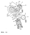
- FIG. 11 is an illustration for describing a fourth embodiment in which the control arm is positioned between the swing cam and the camshaft.
- the same reference numerals or symbols as those of FIG. 2 indicate the same or similar components and portions.
- control shaft 13 having a swing axis [a] supports the swing cam 11 for swing movement.
- An offset shaft section 13b having an axis [b] deviating from the axis [a] of the control shaft 13 supports a control arm 20 for swing movement.
- the control arm 20 holds a roller 20a at its distal end by a roller pin 20b for rotation.
- the roller pin 20b is inserted into a slot 11 a of the swing cam 11 so as to slide therein.
- the roller 20a of the control arm 20 moves along the slot 11 a. Consequently, the substantial arm length L c of the control arm 20 varies.
- the rocker shaft 19 supports the rocker arm 9 for swing movement.
- the rocker arm 9 holds a rocker roller 18 for rotation.
- the rocker roller 18 rollingly contacts with the cam surface 16c of the swing cam 11.
- the respective cam surfaces 16c are shaped so as to be different from each other between the cylinder groups. Specifically, an angle range of the base circle section (indicated by the dashed line of FIG. 11) 16e' for the suspendable cylinder group is larger than an angle range of the base circle section (indicated by the actual line of FIG. 11) 16e for the sequentially operable cylinder group.
- the substantial arm length of the control arm 20 varies, and the swing angle of the swing cam 11 varies.
- the valve opening period and lift amount change. Because the shapes of the cam surfaces of the respective swing cams 11 are different from each other between the cylinder groups, the lift amount for the suspendable cylinder group is zero when the rotational angle of the control shaft 13 is in the predetermined range.
- the cylinders of the suspendable cylinder group in the respective banks thus can be suspended.
- deviation amounts of the offset shaft sections 13b can be made differently between them.
- the present teaching is applied to the valve drive device including the camshaft or crankshaft, the swing cams driven by the camshaft or the crankshaft, the intermediate rockers driven by the respective swing cams and the rocker arms swinging together with the intermediate rockers.
- the valve drive device to which the present invention can apply is not limited to the devices of the above embodiments.
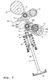
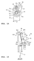
- the present invention can apply to the valve drive device shown in FIGs. 12 to 15.
- a change mechanism 30' is disposed between an intake camshaft 31 and a rocker arm 34.
- the change mechanism 30' includes a swing lever 32 having a roller 32a positioned at a center of the lever 32 and driven by the camshaft 31, and a guide cam 33 which guides a roller 32b positioned at one end of the swing lever 32.
- the other end of the swing lever 32 is coupled with the rocker arm 34. Additionally, one end of the rocker arm 34 is supported by a rush adjuster 35, while the other end thereof can push a top end of the associated intake valve 36.
- the guide cam 33 of the valve drive device 30 functions as the control member.
- a contact point of the swing lever 32 with the roller 32b changes, and the open period and the lift amount of the intake valve 36 varies.
- the cam surfaces 33a of the guide cams 33 are shaped differently from each other between the sequentially operable cylinder group and the suspendable cylinder group. Specifically, the base circle section (indicated by the dashed line of FIG. 12) for the suspendable cylinder group is larger than the base circle section (indicated by the actual line of FIG. 12) for the sequentially operable cylinder group.
- the part of cylinders can be suspended using the valve position sequentially changing valve drive device without requiring a broader space or increasing a parts count and production costs.
- a change mechanism 40' of a valve drive device 40 includes a swing lever 42 having a roller 42a positioned at one end thereof and is driven by a swing lever 42, and a guide cam 43 which guides a roller 42b positioned at a center of the swing lever 42.
- a cam surface 42c of the other end of the swing lever 42 pushes a rocker arm 44.
- one end of the rocker arm 44 is supported by a rush adjuster 45, while the other end thereof can push a top end of the associated intake valve 46.
- a spring 47 urges the swing lever 42 toward the guide cam 43.
- the guide cam 43 of the valve drive device 40 functions as the control member. By pivoting the guide cam 43 in the direction indicated by the arrows of FIG. 13, a contact point of the swing lever 42 with the roller 42b changes, and the open period and the lift amount of the intake valve 46 varies.
- the cam surfaces 43a of the guide cams 43 are shaped differently from each other between the sequentially operable cylinder group and the suspendable cylinder group. Specifically, the base circle section (indicated by the dashed line of FIG. 13) for the suspendable cylinder group is larger than the base circle section (indicated by the actual line of FIG. 13) for the sequentially operable cylinder group.
- the part of cylinders can be suspended using the valve position sequentially changing valve drive device without requiring a broader space or increasing a parts count and production costs.
- a change mechanism 50' is positioned between a drive shaft 51 functioning as the drive source and a lifter 57 functioning as the valve actuator.
- An offset section 51 a is unitarily formed with the drive shaft 51, and supports a base section of a link arm 51 b for relative rotation.
- a distal end 51 c of the link arm 51 b moves up and down in the view of FIG. 14 together with the rotation of the offset section 51 a.
- the change mechanism 50' includes a rocker link 52 having one end coupled with the distal end 51 c of the link arm 51 b and a swing cam 54 coupled with the other end of the rocker link 52 through a link plate 53.
- the rocker link 52 swings.
- the swing movement of the rocker link 52 is transmitted to the swing cam 54 through the link plate 53 to swing the swing cam 54.
- the swing cam 54 then moves the lifter 57, which in turn actuates the intake valve 56.
- An offset section 52b formed on a control shaft 52a supports the rocker link 52 for relative rotation.
- a swing center of the rocker link 52 changes.
- a transmission state of the rotation of the crankshaft 51 to the lifter 52 varies.
- the open period and the lift amount of the intake valve 56 are changed, accordingly.
- the cam surfaces 54a of the swing cams 54 are shaped differently from each other between the sequentially operable cylinder group and the suspendable cylinder group.
- the base circle section for the suspendable cylinder group is larger than the base circle section for the sequentially operable cylinder group.
- the part of cylinders can be suspended using the valve position sequentially changing valve drive device without requiring a broader space or increasing a parts count and production costs.
- the swing cam 54 is compulsively swung in both of the opening direction and the closing direction with the rotation of the crankshaft 51.
- the intake valve thus can certainly open and close the intake ports.
- a change mechanism 60' is positioned between a camshaft 61 functioning as the drive source and a rocker arm 62 functioning as the valve actuator.
- the change mechanism 60' includes a swing cam 63 and a cam supporting mechanism 64 which controls a position of a fulcrum roller 63a attached to a top end of the swing cam 63.
- the cam supporting mechanism 64 includes a guide member 64a for guiding the fulcrum roller 63a along a guide circle which center is a roller 62a of the rocker arm 62, and a cam shaft 64b for moving the fulcrum roller 63a.
- a roller 63b driven by the camshaft 61 is attached to a middle portion of the swing cam 63.
- a bottom end of the swing cam 63 has a cam surface 63c which pushes the roller 62a of the rocker arm 62.
- the cam surfaces 63a of the swing cams 63 are shaped differently from each other between the sequentially operable cylinder group and the suspendable cylinder group.
- the base circle section (indicated by the dashed line of FIG. 15) 63e' for the suspendable cylinder group is larger than the base circle section (indicated by the actual line of FIG. 15) 63e for the sequentially operable cylinder group.
- the part of cylinders can be suspended using the valve position sequentially changing valve drive device without requiring a broader space or increasing a parts count and production costs.
- a multiple cylinder engine including multiple cylinders, intake and exhaust valves opening and closing intake and exhaust ports of the respective cylinders, a drive shaft functioning as a drive source, a valve actuator to which rotational movement of the drive shaft is transmitted, the valve actuator actuating one of the valves of the respective cylinders, a change mechanism having a control member which control amount is variable to change a transmission state of the rotational movement transmitted from the drive shaft to the valve actuator, the change mechanism sequentially changing an open period and a lift amount of each valve by changing the control amount of the control member.
- the cylinders are divided into multiple cylinder groups.
- the control member is common to the respective cylinder groups.
- the transmission states for the respective cylinder groups differ from each other in accordance with the control amount of the control member.
- the valve open period and the lift amount of the each valve of a part of the cylinder groups are capable of being set to zero in a predetermined operational range so as to suspend an operation of the part of the cylinder groups.
- the division of cylinders into multiple cylinder groups means to include a case such that two cylinders are divided into two groups and also include a case such that cylinders of each bank of a V-type engine are divided into multiple cylinder groups.
- the control amount of the control member according to this embodiment means a rotational angle if the control member is provided for pivotal movement and also means a slide angle if the control member is provided for slide movement.
- the control member is common to the respective cylinder groups, and the transmission states for the respective cylinder groups differ from each other in accordance with the control amount of the control member.
- the valve open period and the lift amount for the part of the cylinder groups can be zero, and the operation of the part of the cylinder groups can be suspended without having multiple control members. Therefore, in comparison with a structure having the multiple control members, an arrangement space for the structure of the present invention can be easily obtained.
- the structure of the present invention is not complicated, and the parts count and production costs do not increase.
- valve position sequentially changing valve drive device sequentially changes the valve lift amount of the part of the cylinder groups to suspend and restart the operation of the part of the cylinder groups.
- the mode changes from the whole cylinder operating mode to the part cylinder suspended mode and from the part cylinder suspended mode to the whole cylinder operating mode can be smoothly made. Any shocks following the mode changes can be reduced.
- the description discloses a further embodiment (second aspect) of the multiple cylinder engine in which the drive shaft includes a camshaft driven by a crankshaft.
- the valve actuator includes a rocker arm supported for swing movement.
- the change mechanism includes a swing cam supported for swing movement to follow the camshaft.
- a control arm is positioned between the swing cam and the camshaft or the rocker arm and is supported by the control member for swing movement.
- the control amount of the control member is varied to change a relative relationship between a position of control arm and a position of the camshaft or a position of swing cam so as to sequentially change the open period and the lift amount of the intake valve.
- a cam surface of the swing cam has a shape which differs from each other between the cylinder groups.
- the cam surface of the swing cam for the part of the cylinder groups is configured to bring the valve lift amount to zero when the control amount of the control member is in the predetermined range.
- the description discloses a further embodiment (third aspect) of the multiple cylinder engine in which the control arm is positioned between the cam surface of the swing cam and the rocker arm. A relative relationship between a position of the control arm and a position of the cam surface is changed when a rotational angle of the control member is changed. Thereby, the open period and the lift amount of the each intake valve are sequentially controllable.
- the control member supports the control arm for swing movement, and the control amount of the control member is varied to change the relative relationship between the position of the control arm and the position of the camshaft or the swing cam or the position of the swing cam, and the cam surface of the swing cam is configured to bring the valve lift amount to zero when the control amount of the control member is in the predetermined range. Therefore, the part cylinder suspended mode can be realized even though the common control member is used.
- the description discloses a further embodiment (fourth aspect) of the multiple cylinder engine in which the cam surface of the swing cam is formed as a circular arc which center is consistent with a center of the swing movement of the swing cam.
- the cam surface includes a base circle section that makes the valve lift amount zero irrespective of a swing angle of the swing cam and a lift section which increases the valve lift amount with the swing angle increasing.
- the base circle section of the swing cam for the part of the cylinder groups has an angular range broader than the base circle section of the swing cam for the remainder part of the cylinder groups.
- the base circle section of the swing cam for the part of the cylinder groups has the angular range broader than the base circle section of the swing cam for the remainder part of the cylinder groups.
- the lift section of the swing cam for the part of the cylinder groups has a shape which becomes more similar to a shape of the lift section of the swing cam for the remainder part of the cylinder groups as the lift section of the swing cam for the part of the cylinder groups is spaced apart from a border thereof with the base circle becomes larger.
- the lift section of the swing cam for the part of the cylinder groups has the shape which becomes more similar to the shape of the lift section of the swing cam for the remainder part of the cylinder groups as the lift section of the swing cam for the part of the cylinder groups is spaced apart from the border thereof with the base circle becomes larger. Therefore, in the whole cylinder operation range, particularly, in a high speed and high load range, the valve lift amount for the part of the cylinder groups can be equalized to the valve lift amount for the remainder part of the cylinder groups. The shocks following the mode changes can be avoided. In addition, because the operation suspended mode is used, the maximum power of the engine does not fall.
- the drive shaft includes a camshaft driven by a crankshaft.
- the valve actuator includes a rocker arm supported for swing movement.
- the change mechanism includes a swing cam supported for swing movement to follow the camshaft.
- a control arm is positioned between the swing cam and the camshaft or the rocker arm and supported by the control member for swing movement. The control amount of the control member is varied to change a relative relationship between a position of the control arm and a position of the camshaft or a position of the swing cam so as to sequentially change the open period and the lift amount of the intake valve.
- a relative relationship between a position of the control arm and a position of the camshaft or a position of the swing cam differs from each other between the cylinder groups.
- the relative relationship for the part of the cylinder groups is determined to bring the valve lift amount to zero when the control amount of the control member is in the predetermined range.
- the control shaft is coupled with the control member at a position which is out of a pivot center of the control member.
- a deviation amount of the control shaft for the part of the cylinder groups from the center of the control member is larger than a deviation amount of the control shaft for the remainder part of the cylinder groups from the center of the control member.
- a contact portion at which the control shaft for the part of cylinder groups contacts with a cam surface retreats toward a base circle section of the cam surface more than a contact portion at which the control shaft for the remainder part of cylinder groups contacts with an associated cam surface when the control member is in a predetermined angle range.
- the relative relationship between the position of the control arm and the position of the camshaft differs from each other between the cylinder groups.
- the deviation amount of the control shaft for the part of the cylinder group from the center of the control member is larger than the deviation amount of the control shaft for the remainder part of the cylinder group from the center of the control member; thereby, when the control member is in the predetermined angle range, the control arm for the part of the cylinder groups can be retreat more than the control arm for the remainder part of the cylinder groups. Therefore, the valve lift amount for the part of the cylinder groups can be zero, and the operation of the part of the cylinder groups can be suspended. That is, the part cylinder suspended mode can be realized only by the simple structure in which the deviation amount of the control arm from the center of the control member is properly set.
- control shaft for the part of cylinder groups is shorter than the control shaft for the remainder part of cylinder groups.
- the contact portion of the control shaft for the part of cylinder groups with the cam surface and the contact portion of the control shaft for the remainder part of cylinder groups with the cam surface approach each other closer.
- the control shaft for the part of cylinder groups is shorter than the control shaft for the remainder part of cylinder groups.
- the contact portion of the control shaft for the part of cylinder groups with the cam surface and the contact portion of the control shaft for the remainder part of cylinder groups with the cam surface approach each other closer when the control member leaves from the predetermined angle range further. Accordingly, in the whole cylinder operating range, particularly, in a high speed and high load range, the valve lift amount for the part of the cylinder group can be equalized to the valve lift amount for the remainder part of the cylinder groups.
- the maximum power of the engine does not fall.
- an embodiment in order to provide a multiple cylinder engine that can suspend an operation of a part of cylinders without having a complicated structure or increasing production costs in which these cylinders are divided into multiple cylinder groups, a control member 13 is common to the respective cylinder groups, transmission states of a cam shaft 8 for the respective cylinder groups differ from each other in accordance with a control amount of the control member 13, and a valve open period and a lift amount of a valve of a part of the cylinder groups can be set to zero in a predetermined operational range so as to suspend an operation of the part of the cylinder groups.
- a multiple cylinder engine comprising multiple cylinders, intake and exhaust valves opening and closing intake and exhaust ports of the respective cylinders, a drive shaft functioning as a drive source, a valve actuator to which rotational movement of the drive shaft is transmitted, the valve actuator actuating one of the valves of the respective cylinders, a change mechanism having a control member which control amount is variable to change a transmission state of the rotational movement transmitted from the drive shaft to the valve actuator, the change mechanism sequentially changing an open period and a lift amount of each valve by changing the control amount of the control member, wherein the cylinders are divided into multiple cylinder groups, the control member is common to the respective cylinder groups, the transmission states for the respective cylinder groups differ from each other in accordance with the control amount of the control member, and the valve open period and the lift amount of said each valve of a part of the cylinder groups are capable of being set to zero in a predetermined operational range so as to suspend an operation of the part of the cylinder groups.
- the drive shaft includes a camshaft driven by a crankshaft
- the valve actuator includes a rocker arm supported for swing movement
- the change mechanism includes a swing cam supported for swing movement to follow the camshaft
- a control arm positioned between the swing cam and the camshaft or the rocker arm and supported by the control member for swing movement
- the control amount of the control member is varied to change a relative relationship between a position of control arm and a position of the camshaft or a position of swing cam so as to sequentially change the open period and the lift amount of the valve
- a cam surface of the swing cam has a shape which differs from each other between the cylinder groups
- the cam surface of the swing cam for the part of the cylinder groups is configured to bring the valve lift amount to zero when the control amount of the control member is in the predetermined range.
- control arm is positioned between the cam surface of the swing cam and the rocker arm, a relative relationship between a position of the control arm and a position of the cam surface is changed when a rotational angle of the control member is changed; thereby, the open period and the lift amount of said valve is sequentially controllable.
- the cam surface of the swing cam includes a base circle section and a lift section
- the base circle section is formed as a circular arc which center is consistent with a center of the swing movement of the swing cam and makes the valve lift amount zero irrespective of a swing angle of the swing cam
- the lift section increases the valve lift amount with the swing angle increasing
- the base circle section of the swing cam for the part of the cylinder groups has an angular range broader than the base circle section of the swing cam for the remainder part of the cylinder groups.
- the lift section of the swing cam for the part of the cylinder groups has a shape which becomes more similar to a shape of the lift section of the swing cam for the remainder part of the cylinder groups as the lift section of the swing cam for the part of the cylinder groups is spaced apart from a border thereof with the base circle toward the lift section.
- the drive shaft includes a camshaft driven by a crankshaft
- the valve actuator includes a rocker arm supported for swing movement
- the change mechanism includes a swing cam supported for swing movement to follow the camshaft
- a control arm positioned between the swing cam and the camshaft or the rocker arm and supported by the control member for swing movement
- the control amount of the control member is varied to change a relative relationship between a position of the control arm and a position of the camshaft or a position of the swing cam so as to sequentially change the open period and the lift amount of the valve
- a relative relationship between a position of the control arm and a position of the camshaft or a position of the swing cam differs from each other between the cylinder groups
- the relative relationship for the part of the cylinder groups is determined to bring the valve lift amount to zero when the control amount of the control member is in the predetermined range.
- the control arm is coupled with the control member at a position which is out of a pivot center of the control member, a deviation amount of the control arm for the part of the cylinder groups from the center of the control member is larger than a deviation amount of the control arm for the remainder part of the cylinder groups from the center of the control member, a contact portion at which the control arm for the part of cylinder groups contacts with a cam surface retreats toward a base circle section of the cam surface more than a contact portion at which the control arm for the remainder part of cylinder groups contacts with an associated cam surface when the control member is in a predetermined angle range.
- control arm for the part of cylinder groups is shorter than the control arm for the remainder part of cylinder groups, as the control member leaves from the predetermined angle range further, the contact portion of the control arm for the part of cylinder groups with the cam surface and the contact portion of the control arm for the remainder part of cylinder groups with the cam surface approach each other closer.
Landscapes
- Engineering & Computer Science (AREA)
- Mechanical Engineering (AREA)
- General Engineering & Computer Science (AREA)
- Chemical & Material Sciences (AREA)
- Combustion & Propulsion (AREA)
- Valve Device For Special Equipments (AREA)
- Valve-Gear Or Valve Arrangements (AREA)
- Engine Equipment That Uses Special Cycles (AREA)
- Output Control And Ontrol Of Special Type Engine (AREA)
Abstract
Description
- The present invention relates to an engine comprising multiple cylinders, and in particular to a multi-cylinder engine, wherein an open period and a lift amount of an intake valve or an exhaust valve of each cylinder is sequentially controllable.
- A valve drive device for an engine is used, by which open periods and lift amounts of intake and exhaust valves sequentially controllable. Conventionally, for example, this kind of valve drive device is constructed so that a camshaft drives a swing cam supported for swing movement and the swing cam actuates an intake valve or an exhaust valve between open and close positions. A center of the swing movement of the swing cam is variable, and an open period and a lift amount of the valve can be sequentially changed when the center of the swing movement is varied.
- On the other hand, in order to improve the fuel consumption, an engine which can operate in the so-called "cylinder suspended mode" ― a mode in which an operation of a part of cylinder groups is suspended in a low load range - is proposed.
JP-A-2004-316571 - In the engine described in
JP-A-2004-316571 - Meanwhile, the conventional engine realizing the cylinder suspended mode operation has multiple control shafts and employs a system in which the respective control shafts are controlled to have different rotational angles. However, it is quite difficult to ensure a space for the multiple control shafts in the engine that has the valve drive device by which the open period and the lift amount of respective valves are sequentially varied. In addition, the structure of the valve drive device is inevitably complicated and production costs thereof can increase.
- The present invention is made in view of the problems discussed above and aims to provide a multiple cylinder engine that can suspend an operation of a part of cylinders without having a complicated structure or increasing production costs.
- This objective is solved in an inventive manner by an engine comprising multiple cylinders being divided into multiple cylinder groups, each cylinder group comprising a change mechanism transmitting a drive force of a drive source to each of the valves of the respective cylinder group, wherein a control amount is variable to change a transmission state of the drive force of the drive source transmitted to the valves of the respective cylinder group, and wherein a valve open period and a valve lift amount of at least a first cylinder group is capable to be set to zero in a predetermined operational range to suspend an operation of said first cylinder group.
- Preferably, the change mechanism is configured to sequentially change the open period and the lift amount of each valve by changing the control amount of the control member, and wherein the transmission states for the respective cylinder groups differ from each other in accordance with the control amount of the control member.
- Further, preferably the engine further comprises intake and exhaust valves opening and closing intake and exhaust ports of the respective cylinders, a drive shaft functioning as the drive source, and a valve actuator to which a rotational movement of the drive shaft is transmitted, the valve actuator actuating one of the valves of the respective cylinders, wherein the control amount of the control member of the change mechanism is variable to change the transmission state of the rotational movement transmitted from the drive shaft to the valve actuator, the change mechanism sequentially changing an open period and a lift amount of each valve by changing the control amount of the control member, and wherein the control member is common to the respective cylinder groups, and the transmission states for the respective cylinder groups differ from each other in accordance with the control amount of the control member, and the valve open period and the lift amount of said each valve of at least the first cylinder group are capable of being set to zero in a predetermined operational range so as to suspend an operation of the part of the cylinder groups.
- According to a further preferred embodiment, the drive shaft includes a camshaft driven by a crankshaft, wherein the valve actuator includes a rocker arm supported for swing movement, wherein the change mechanism includes a swing cam supported for swing movement to follow the camshaft, wherein a control arm is positioned between the swing cam and the camshaft or the rocker arm and is supported by the control member for swing movement, the control amount of the control member being varied to change a relative relationship between a position of control arm and a position of the camshaft or a position of swing cam so as to sequentially change the open period and the lift amount of the valve, and wherein a cam surface of the swing cam has a shape which differs from each other between the cylinder groups, the cam surface of the swing cam for at least the first cylinder group being configured to bring the valve lift amount to zero when the control amount of the control member is in the predetermined range.
- Therein, it is preferable if the control arm is positioned between the cam surface of the swing cam and the rocker arm, and wherein a relative relationship between a position of the control arm and a position of the cam surface is changed when a rotational angle of the control member is changed whereby the open period and the lift amount of said valve is sequentially controllable.
- Therein, it is still further preferred if the cam surface of the swing cam includes a base circle section and a lift section, the base circle section is formed as a circular arc which center is consistent with a center of the swing movement of the swing cam and makes the valve lift amount zero irrespective of a swing angle of the swing cam, the lift section increases the valve lift amount with the swing angle increasing, and the base circle section of the swing cam for the part of the cylinder groups has an angular range broader than the base circle section of the swing cam for the remainder part of the cylinder groups.
- Therein, it is yet further preferred if the lift section of the swing cam for at least the first of the cylinder groups has a shape which becomes more similar to a shape of the lift section of the swing cam for the remainder part of the cylinder groups as the lift section of the swing cam for at least the first of the cylinder groups is spaced apart from a border thereof with the base circle toward the lift section.
- According to yet another preferred embodiment, the drive shaft includes a camshaft driven by a crankshaft, wherein the valve actuator includes a rocker arm supported for swing movement, wherein the change mechanism includes a swing cam supported for swing movement to follow the camshaft, wherein a control arm is positioned between the swing cam and the camshaft or the rocker arm and is supported by the control member for swing movement, wherein the control amount of the control member is varied to change a relative relationship between a position of the control arm and a position of the camshaft or a position of the swing cam so as to sequentially change the open period and the lift amount of the valve, and wherein a relative relationship between a position of the control arm and a position of the camshaft or a position of the swing cam differs from each other between the cylinder groups, the relative relationship for at least the first of the cylinder groups being determined to bring the valve lift amount to zero when the control amount of the control member is in the predetermined range.
- Therein, it is preferred if the control arm is coupled with the control member at a position which is out of a pivot center of the control member, a deviation amount of the control arm for at least the first of the cylinder groups from the center of the control member being larger than a deviation amount of the control arm for the remainder part of the cylinder groups from the center of the control member, and wherein a contact portion at which the control arm for at least the first of the cylinder groups contacts with a cam surface retreats toward a base circle section of the cam surface more than a contact portion at which the control arm for the remainder part of cylinder groups contacts with an associated cam surface when the control member is in a predetermined angle range.
- Therein, it is further preferred if the control arm for at least the first of the cylinder groups is shorter than the control arm for the remainder part of the cylinder groups, wherein, as the control member leaves from the predetermined angle range further, the contact portion of the control arm for at least the first of the cylinder groups with the cam surface and the contact portion of the control arm for the remainder part of the cylinder groups with the cam surface approach each other closer.
- In the following, the present invention is explained in greater detail with respect to several embodiments thereof in conjunction with the accompanying drawings, wherein:
- FIG. 1
- is a cross sectional, side elevational view of a valve drive device for a multiple cylinder engine configured in accordance with a first embodiment,
- FIG. 2
- is a cross sectional, side elevational view of the device of the first embodiment,
- FIG.3
- is a cross sectional, side elevational view of the device of the first embodiment,
- FIG.4
- is an enlarged view of a swing cam surface of the device of the first embodiment,
- FIG. 5
- is a layout view of an engine of the first embodiment,
- FIG. 6
- is a control characteristic diagram for the device of the first embodiment,
- FIG. 7
- is a cross sectional, side elevational view of a valve drive device of a second embodiment,
- FIG. 8
- is a cross sectional, side elevational view of the device of the second embodiment,
- FIG. 9
- is an enlarged schematic view of the major part of the device of the second embodiment,
- FIG. 10
- is a cross sectional, side elevational view of a valve drive device of a third embodiment,
- FIG. 11
- is a schematic view of a valve drive device of a fourth embodiment,
- FIG. 12
- is a schematic view of a valve drive device of a fifth embodiment,
- FIG. 13
- is a schematic view of a valve drive device of a sixth embodiment,
- FIG. 14
- is a schematic view of a valve drive device of a seventh embodiment, and
- FIG. 15
- is a schematic view of a valve drive device of an eighth embodiment.
-
- 1e:
- intake port
- 1f:
- exhaust port
- 2:
- intake valve
- 3:
- exhaust valve
- 8:
- intake cam shaft (drive shaft)
- 9:
- intake rocker arm (valve actuator)
- 10:
- change mechanism
- 11:
- intake swing cam
- 12:
- intermediate intake rocker
- 13:
- control shaft
- 16c:
- cam surface
- 16e:
- base circle section
- 16f:
- lift section
- C, C':
- border between the base circle section and the lift section
- a:
- swing center of the swing cam
- b:
- axis of the control shaft
- c1, c2:
- deviation amount from the axis b
- θ:
- rotational angle of the control shaft
- θ0-θ1:
- rotational angle of the predetermined range
- #1, 7:
- sequentially operable cylinder group of the left bank (the remainder cylinder group)
- #3, 5:
- suspendable cylinder group of the left bank (part of cylinder group)
- With reference to attached drawings, an embodiment will be described below.
- FIGs. 1 to 6 are illustrations for describing a multiple cylinder engine configured in accordance with a first embodiment. FIGs. 1 to 3 are cross sectional, side elevational views of a valve drive device. FIG. 4 is an enlarged view of a swing cam. FIG. 5 is a schematic view for describing cylinder groups. FIG. 6 is a characteristic diagram showing relationships between a control shaft rotational angle θ and the largest lift [H].
- The engine of this embodiment is a V-type, eight cylinder engine including a left bank which has four cylinders (#1, 3, 5 and 7 of FIG. 5) and a right bank which has four cylinders (#2, 4, 6 and 8 of FIG. 5). The large arrow of FIG. 5 indicates a front side of the engine. The reference symbols R and L indicate the right bank and the left bank, respectively.
- Each right and left bank has a cylinder block, a
cylinder head 1 coupled with a top end of the cylinder block and ahead cover 2 detachably attached to thecylinder head 1. FIG. 1 is a cross sectional view taken along the line I-I of FIG. 5 (the cylinder #5 of the left bank). - A portion of a surface 1 a of each
cylinder head 1 facing the respective cylinder block is recessed to define combustion chambers 1b.Intake ports 1c and exhaust ports 1d open to each combustion chamber 1b. Eachintake port 1 c and each exhaust port 1d are connected to openings defined in an inner side wall 1j of the bank and anouter side wall 1 k of the bank through an intake passage 1 e and anexhaust passage 1 f, respectively. - A
valve head 2a of anintake valve 2 and avalve head 3a of anexhaust valve 3 are positioned at eachintake port 1 c and each exhaust port 1 d, respectively, to open or close therespective ports 1c, 1d. Valve springs 5a, 5b individually extend betweenretainers respective intake valve 2 and theexhaust valve 3 andspring seats cylinder head 1. Thesprings respective valves valves respective ports 1 c, 1 d. - Intake valve position sequentially changing
valve drive devices 6 are individually provided for the right bank and for the left bank. Exhaust valve position sequentially changingvalve drive devices 7 are individually provided for the right bank and for the left bank. An open period and a lift amount of theintake valve 2 are sequentially variable between zero and the maximum. Also, an open period and a lift amount of theexhaust valve 3 are sequentially variable between zero and the maximum. - In this embodiment, the respective cylinders of the respective banks are divided into a suspendable cylinder group which cylinders are operated in a cylinder suspended mode in which operations of those cylinders are suspended in a low load range, and a sequentially operable cylinder group which cylinders are sequentially operated in the whole ranges. More specifically, the
cylinders # 1 and #7 of the left bank belong to the sequentially operable group, and thecylinders # 3 and #5 of the left bank belong to the suspendable cylinder group. Also, thecylinders # 2 and #8 of the right bank belong to the suspendable cylinder group, and thecylinders # 4 and #6 of the right bank belong to the sequentially operable group. - Each intake valve position sequentially changing
valve drive device 6 and each exhaust valve position sequentially changingvalve drive device 7 have the same structure as one another except for some portions. Therefore, mainly, the intake valve position sequentially changingvalve drive device 6 will be described. Regarding the exhaust valve position sequentially changingvalve drive device 7, the same reference numerals or symbols will be assigned to the components which are the same as the components of the intake side, and only different portions will be described. - The intake valve position sequentially changing
valve drive device 6 includes an intake camshaft (drive shaft) 8, intake rocker arms (valve actuator) 9 receiving rotational movement of thecamshaft 8 transmitted therefrom to actuate theintake valve 2, and achange mechanism 10 positioned between therocker arm 9 and theintake camshaft 8 to change transmission states of the rotational movement transmitted from thecamshaft 8 to theintake rocker arm 9. - The
change mechanism 10 includesintake swing cams 11 driven byintake cam noses 8a of theintake cam shaft 8, intermediate intake rocker arms (control arms) 12 driven by the respectiveintake swing cams 11, and a control shaft (control member) 13 supporting theintermediate intake rockers 12 and theintake rocker arms 9 for swing movement of theintermediate intake rockers 12. Theintake swing cams 11, with its own swing movement, swing the respectiveintake rocker arms 9 via theintermediate intake rockers 12. With the swing movement of therocker arms 9, theintake valves 2 axially move to open or close theintake ports 1 c. - Each
intake valve 2 has one set of theintake cam nose 8a, theintake swing cam 11, theintermediate intake rocker 12 and theintake rocker arm 9. Onecontrol shaft 13 is allotted to the left bank, and anothercontrol shaft 13 is allotted to the right bank. - The
intake camshaft 8 extends parallel to a crankshaft (not shown). Theintake camshaft 8 is fixed to thecylinder head 1 by a camjournal receiving member 1 h attached to thecylinder head 1 and cam caps 1 i attached to a top surface of the camjournal receiving member 1 h for rotation but for not moving axially nor in a direction normal to its axis. Eachcam nose 8a of theintake camshaft 8 has abase circle section 8b having a certain outer diameter and anose section 8c having a predetermined cam profile to open and close the associated intake valve in a suction stroke. - Each
rocker arm 9 is formed with right and left base sections 9a, 9a both having a ring shape, right and leftarm sections bottom wall 9c unitarily joining them. The right and left base sections 9a, 9a are supported by journal sections 13a, 13a of thecontrol shaft 13, which extends parallel to theintake camshaft 8 and is positioned closer to a cylinder axis, for vertical swing movement but for not moving axially nor in a direction normal to those axes. - A
valve pushing surface 9d is formed at a bottom of a tip of thebottom wall 9c so as to push ashim 2c attached to a top end of eachintake valve 2. Inner surfaces of therespective arm sections pressed surfaces pressing surface 12a of theintermediate rocker 12. Each pressedsurface 9e is formed as a circular arc having a radius [r] which center is inconsistent with a swing center [a] of theintake swing cam 11 in a view in the axial direction of the intake camshaft. - An offset
pin section 13b is positioned between thejournal sections 13a, 13b of thecontrol shaft 13. The offsetpin section 13b is unitarily formed with thecontrol shaft 13 so as to deviate outward from an axis [b] of thecontrol shaft 13 in its radius direction. The offsetpin section 13b has an outer diameter smaller than those of other portions of thecontrol shaft 13. - A semi-circular engaging
base section 12b of eachintermediate intake rocker 12 engages the offsetpin section 13b for pivotal movement. Aleaf spring 14 couples the engagingbase section 12b and the offsetpin section 13b with each other so that they are pivotable relative to each other but cannot be separated from one another. - Right and left
arm sections base section 12b of theintermediate intake rocker 12 to extend forward. Arocker roller 12d is positioned between front end portions of the right and leftarm sections cam surface 16c of theswing cam 11. Therocker roller 12d is journaled by a roller pin 12e extending through the right and leftarm sections control shaft 13. Thepressing surfaces arm sections pressing surfaces 12a press the right and left pressedsurfaces 9e of theintake rocker arms 9. - A drive mechanism (not shown) such as, for example, a servo motor rotates the
control shaft 13 and controls a rotational angle θ of thecontrol shaft 13 to be a desired angle. When drive mechanism changes the rotational angle θ of thecontrol shaft 13, therocker roller 12d and thepressing surface 12a of theintermediate intake rocker 12 move along the pressedsurfaces 9e. Thereby, a substantial arm length of therocker arm 9 changes and a position of therocker arm 9 relative to theswing cam 11 also changes. The drive mechanism controls the rotational angle of thecontrol shaft 13 in such a manner that, for example, in accordance with a rotational angle of an accelerator pedal, as the angle becomes larger, an opening and a lift amount of the intake valve become larger. - The offset
pin section 13b pivots along a circle [c] which center is consistent with the axis [b] when thecontrol shaft 13 pivots. When the rotational angle θ of thecontrol shaft 13 is the minimum θ0(for example, 15-20°relative to a reference straight line [A] extending through the axis [b]), the offsetpin section 13b reaches the position 13b1 of FIG. 2(a). Theintermediate rocker 12 thus is positioned at a retreat end (position indicated by the actual line of FIG. 2). More specifically, theintermediate rocker 12 retreats to a position of abase circle section 16e at which a rollingly contacting point of therocker roller 12 with thecam surface 16c is most close to the axis [b] of thecontrol shaft 13. Therefore, both the valve open period and the lift amount are the minimum. When the rotational angle θ of thecontrol shaft 13 is the maximum θmax(for example, 160-165°relative to the reference straight line [A]), the offsetpin section 13b is placed at the position 13b1' of FIG. 2(a). Theintermediate rocker 12 is positioned at an advance end (position at which the rollingly contact point is the furthest from the axis [b]), and both the valve open period and the lift amount are the maximum. - A reason why the minimum rotational angle θ0 and the maximum rotational angle θmax of the
control shaft 13 are set at the positions which are out of the reference straight line [A] is to ensure a proper rate of a variation of theintermediate rocker 12 in a fore to aft direction relative to a variation of the rotational angle of thecontrol shaft 13, i.e., the responsibility. - Each
swing cam 11 includes aswing arm body 16 which is supported by theswing shaft 15 extending parallel to theintake camshaft 8 for swing movement but for not moving axially nor in a direction normal to an axis of theswing shaft 15, and aswing roller 17 journaled by theswing arm body 16. A spring (not shown) urges theswing arm body 16 clockwise in FIG. 2 so that theswing roller 17 rollingly contact with thecam nose 8a all the time. - The
swing arm body 16 has acylindrical base section 16a and anarm section 16b. Both of thesections arm section 16b extends from thebase section 16a which is journaled by theswing shaft 15. Aswing cam surface 16c is unitarily formed at a tip of thearm section 16b. Thearm section 16b has aroller space 16d in which theswing roller 17 is disposed. Theroller space 16d is a slit vertically extending through thearm section 16b. Theroller pin 17a journals theswing roller 17. Theroller pin 17a extends parallel to theswing shaft 15 and through thearm section 16b. - The
swing cam surface 16c includes thebase circle section 16e and alift section 16f ranging to a distal end (i.e., end which is fur spaced from the axis [b] of the control shaft 13) of thebase circle section 16e. Thebase circle section 16e is shaped as a circular arc which center is consistent with the axis [a] of theswing shaft 15 and has a radius [R]. Thus, during a period in which thebase circle section 16e rollingly contacts with therocker roller 12d, the swing angle of theintermediate rocker 12 does not vary and stays at zero, and, in turn, the swing angle of therocker arm 9 does not vary and stays at zero, even though the swing angle of theswing cam 11 varies. Theintake valve 2 is kept at the closing position and its lift amount is zero, accordingly. - On the other hand, as a portion adjacent to the top of the
nose section 8c of theintake camshaft 8 pushes theswing roller 17 larger, i.e., as the swing angle of theswing cam 11 becomes larger, thelift section 16f swings theintermediate rocker 12 larger, and, in turn, theintermediate rocker 12 swings therocker arm 9 larger and lifts theintake valve 2 larger. - The
swing cam surface 16c for the sequentially operable cylinder group and theswing cam surface 16 for the suspendable cylinder group differ from each other. More specifically, as shown in FIG. 4, a border C' between thebase circle section 16e' and thelift section 16f' of theswing cam surface 16c' (see FIG. 4(b)) is deviated toward thelift section 16f more than a border C of theswing cam surface 16c (see FIG. 4(a)). That is, thebase circle section 16e' for the suspendable cylinder group is broader than thebase circle section 16 for the sequentially operable cylinder group by the area between the borders C-C' shown in FIG. 4(b). - On the other hand, as the
lift section 16f' for the suspendable cylinder group is spaced apart from the border C' further, a shape of thelift section 16f becomes more similar to a shape of thelift section 16f for the sequentially operable cylinder group. In this embodiment, the major part of the shape of thelift section 16f' is the same as the shape of thelift section 16f. - Because the shapes of the respective cam surfaces differ from each other, the open periods and the lift amounts of the
respective intake valves 2 are controlled based upon control characteristics which are different between one for the sequentially operable cylinder group and the other for the suspendable cylinder group. The control characteristics will be described based upon the characteristic curves of FIG. 6 which is indicative of relationships between the control shaft rotational angle (θ) and the largest lift (H). - In FIG. 6, the horizontal axis indicates the rotational angle θ, while the vertical axis indicates the largest lift [H] when the control shaft is in a certain rotational angle θ.
- Regarding the sequentially operable cylinder group (#1, 4, 6 and 7), as indicated by the chain double-dashed line of FIG. 6, the largest lift [H] smoothly increase from 0 to the maximum with the rotational angle θ of the
control shaft 13 increasing from θ0 to θmax. - On the other hand, regarding the suspendable cylinder group (#2, 3, 5 and 8), as indicated by the actual line of FIG. 6, the largest lift [H] is kept to be zero before the rotational angle θ of the
control shaft 13 increases from θ0 to θ1. When the rotational angle θ of thecontrol shaft 13 further increases from θ1, the largest lift [H] starts increasing. When the rotational angle θ exceeds θ2, the largest lift [H] becomes equal to the largest lift [H] for the sequentially operable cylinder group. - For example, in a high speed and high load range, the
control shaft 13 is driven so that the rotational angle θ becomes, for example; θmax. Under this condition, the respectiveintermediate rockers 12 are positioned at the advance ends, the largest lift [H] of the valves for both of the sequentially operable cylinder group and the suspendable cylinder group becomes the maximum. - On the other hand, as the operation of the engine approaches a middle speed and middle load range further, the
control shaft 13 is driven so that the rotational angle θ becomes smaller. For example, when the rotational angle θ becomes smaller than θ2, the largest lift for the suspendable cylinder group becomes smaller than the largest lift for the sequentially operable cylinder group as shown in FIG. 6. When the rotational angle θ becomes smaller than θ1, the largest lift for the suspendable cylinder group becomes zero. Thus, the operation of the cylinders of the suspendable cylinder group is suspended. Regarding the sequentially operable cylinder group, the largest lift gradually decreases with the rotational angle θ of thecontrol shaft 13 decreasing. - As thus described, in the embodiment, the operation of the cylinders of the suspendable cylinder group can be suspended while the operation of the sequentially operable cylinder group is continued using the valve position sequentially changing valve drive device. In addition, for example, if attention is paid to the left bank, even though the single and
common control shaft 13 controls all of thecylinders # cylinders # remainder cylinders # 3 and 5 can be suspended. Thus, differently from the conventional devices, this device does not need to have two control shafts. A space for the control shaft can be easily ensured. The structure is not complicated, and the parts count and production costs do not increase. - The simple structure in which the cam surfaces 16c of the
swing cams 11 differ from each other, one for the suspendable cylinder group and the other for the sequentially operable cylinder group. - In this embodiment, when a mode in which all cylinders operate is changed to another mode in which some part of the cylinders are suspended, first, the largest lift for the suspendable cylinder group gradually decreases, and then the operation of the cylinders of this group is suspended. Similarly, when the mode in which some part of the cylinders are suspended is changed to the mode in which all cylinders operate, the largest lift for the restarting cylinders gradually increases. Therefore, the change to the part cylinder suspended mode or to return to the whole cylinder operating mode can be smoothly made. Any shocks following the mode changes can be removed.
- A problem can arise such that the maximum power of the engine, particularly, in the high speed and high load range may decrease because the cylinder suspended operation is realized. In this embodiment, when the rotational angle θ exceeds θ2, the largest lift for the suspendable cylinder group becomes consistent with the largest lift for the sequentially operable cylinder group. The problem thus can be avoided.
- Additionally, the right bank operates similarly to the left bank discussed above. The right bank thus can have the same actions and can enjoy the same advantages. Also, the exhaust valve position sequentially changing valve drive devices in the right and left banks operate similarly, and thus can have the same actions and can enjoy the same advantages.
- In the embodiment, by setting the cam surfaces of the swing cams for the suspendable cylinder group differently from those for the sequentially operable cylinder group, the single control shaft sequentially changes the valve opening periods and the lift amounts of both of the banks so as to realize the suspension of the operation of the part of the cylinders. The first embodiment discussed above, however, does not limit ways for realizing the suspension of the operation of the part of the cylinders.
- FIGs. 7 to 9 are illustrations for describing a second embodiment. In those figures, the same reference numerals or symbols as those of FiGs. 1 to 3 indicate the same or similar components and portions.
- In the second embodiment, a deviation amount [c] of each offset
pin section 13b from the axis [b] of thecontrol shaft 13 and an arm length of eachintermediate rocker 12 are differently set between the sequentially operable cylinder group and the suspendable cylinder group; thereby, the same actions and effects as those of the first embodiment can be obtained. - Specifically, as shown in FIG. 9, when the
control shaft 13 pivots, each offset pin section 13b1 for the suspendable cylinder group pivots along an offset circle [c1] which deviation amount from the axis [b] is [c1], while each offset pin section 13b2 for the sequentially operable cylinder group pivots along an offset circle [c2] which deviation amount from the axis [b] is [c2]. The amount [c1] is larger than the amount [c2]. Also, a length of each intermediate rocker arm 12c2 for the sequentially operable cylinder group is longer than a length of each intermediate rocker arm 12c1 for the suspendable cylinder group by the length (c1-c2)/2. - Therefore, when the rotational angle of the
control shaft 13 is the minimum θ0, the rocker rollers 12d1 for the suspendable cylinder group retreat more than the rocker rollers 12d2 for the sequentially operable cylinder group. More specifically, a rollingly contacting point of each rocker roller 12d1 for the suspendable cylinder group with thecam surface 16c is positioned at a location adjacent to the axis [b] of thecontrol shaft 13. On the other hand, when the rotational angle of thecontrol shaft 13 is the maximum θmax, the rocker rollers 12d1 for the suspendable cylinder group and the rocker rollers 12d2 for the sequentially operable cylinder group are positioned at the same locations in the fore to aft direction. - Thus, the open period and the lift amount of each
intake valve 2 are controlled based upon characteristics which differ from each other between the sequentially operable cylinder group and the suspendable cylinder group. Specifically, they are controlled to change along the dashed line of FIG. 6. - With reference to FIG. 6, regarding the sequentially operable cylinder group (#1, 4, 6 and 7), similarly to the first embodiment, the largest lift [H] smoothly varies from 0 to the maximum while the rotational angle θ increases from θ0 to θmax.
- On the other hand, regarding the suspendable cylinder group (#2, 3, 5 and 8), the largest lift [H] is kept to be zero before the rotational angle θ of the
control shaft 13 increases from θ0 to θ1. When the rotational angle θ of thecontrol shaft 13 further increases from θ1, the largest lift [H] starts increasing. With the rotational angle θ increasing much more, the largest lift for the suspendable cylinder group gradually approaches the largest lift for the sequentially operable cylinder group, and the largest lifts for both of the groups become equal to each other when the rotational angle approaches to the vicinity of the maximum θmax. - In the second embodiment, the same actions and effects as those of the first embodiment can be obtained. Particularly, the largest lift for the suspendable cylinder group becomes gradually smaller than the largest lift for the sequentially operable cylinder group when the rotational angle of the
control shaft 13 becomes smaller than the maximum θmax. Thus, the changes between the whole cylinder operating mode and the part cylinder suspended mode can be more smoothly made, and any shocks following the mode changes can be almost completely removed. - The cylinder partially suspended control can be realized simply by the structure in which the deviation amount of each offset
pin 13b from the axis [b] of thecontrol shaft 13 and the length of eachintermediate rocker 12 are set differently. - In the first and second embodiments, the drive shaft acting as the drive source for actuating the valves is the camshaft, and each swing cam is compulsively swung toward the opening position and the swing cam is urged to swing toward the closing position by the spring. However, as shown in FIG. 3, a third embodiment includes an alternative in which the swing cam is compulsively swung toward both of the opening and closing positions. In FIG. 10, the same reference numerals or symbols as those of FIG. 2 indicate the same or similar components and portions.
- In the third embodiment, a
crankshaft 90 replaces the camshaft. Thecrankshaft 90 includes ashaft body 90a, a pair of disk-like crankarms shaft body 90a, and acrank pin 90c positioned between thecrank arms shaft body 90a in a radius direction. - A connecting
rod 91 connects thecrankshaft 90 and thearm body 16 of theswing cam 11 to each other. Oneend 91 a of the connectingrod 91 is coupled with thecrank pin 90c, while theother end 91b thereof is coupled with thearm body 12. In the third embodiment, the urgingspring 14 used in the first and second embodiments is not necessary. - In the third embodiment, the
swing cam 11 is compulsively swung toward both of the valve opening and closing directions together with thecrankshaft 90 rotating. For example, whole of the cylinders of the sequentially operable cylinder group and the suspendable cylinder group are operated in the high speed and high load range, while only the cylinders of the suspendable cylinder group are suspended in the low speed and low load range because the largest lift for the suspendable cylinder group is kept at zero. - As thus discussed, because the
crankshaft 90 compulsively swings theswing cam 11 in both of the opening and closing directions in this embodiment, thecam surface 16c of theswing cam 11 can certainly pushes therocker arm 9 down, and, in turn, theintake valve 2 can certainly open and close the intake port. - In the first through third embodiments, each control arm (intermediate rocker) 12 is interposed between the
swing cam 11 and therocker arm 9. However, the position of the control arm according to the present invention is not limited to those in the embodiments. - FIG. 11 is an illustration for describing a fourth embodiment in which the control arm is positioned between the swing cam and the camshaft. The same reference numerals or symbols as those of FIG. 2 indicate the same or similar components and portions.
- In this figure, the
control shaft 13 having a swing axis [a] supports theswing cam 11 for swing movement. An offsetshaft section 13b having an axis [b] deviating from the axis [a] of thecontrol shaft 13 supports acontrol arm 20 for swing movement. Thecontrol arm 20 holds aroller 20a at its distal end by aroller pin 20b for rotation. Theroller pin 20b is inserted into aslot 11 a of theswing cam 11 so as to slide therein. When thecontrol shaft 13 pivots, theroller 20a of thecontrol arm 20 moves along theslot 11 a. Consequently, the substantial arm length Lc of thecontrol arm 20 varies. - The
rocker shaft 19 supports therocker arm 9 for swing movement. Therocker arm 9 holds arocker roller 18 for rotation. Therocker roller 18 rollingly contacts with thecam surface 16c of theswing cam 11. - Similarly to the first through third embodiments, the respective cam surfaces 16c are shaped so as to be different from each other between the cylinder groups. Specifically, an angle range of the base circle section (indicated by the dashed line of FIG. 11) 16e' for the suspendable cylinder group is larger than an angle range of the base circle section (indicated by the actual line of FIG. 11) 16e for the sequentially operable cylinder group.
- In this embodiment, by controlling the rotational angle of the
control shaft 13, the substantial arm length of thecontrol arm 20 varies, and the swing angle of theswing cam 11 varies. Thereby, the valve opening period and lift amount change. Because the shapes of the cam surfaces of therespective swing cams 11 are different from each other between the cylinder groups, the lift amount for the suspendable cylinder group is zero when the rotational angle of thecontrol shaft 13 is in the predetermined range. The cylinders of the suspendable cylinder group in the respective banks thus can be suspended. - Instead of making the shapes of the cam surfaces differently between the cylinder groups, deviation amounts of the offset
shaft sections 13b can be made differently between them. - In the first through fourth embodiments, the present teaching is applied to the valve drive device including the camshaft or crankshaft, the swing cams driven by the camshaft or the crankshaft, the intermediate rockers driven by the respective swing cams and the rocker arms swinging together with the intermediate rockers. However, the valve drive device to which the present invention can apply is not limited to the devices of the above embodiments. The present invention can apply to the valve drive device shown in FIGs. 12 to 15.
- In a
valve drive device 30 of a fifth embodiment shown in FIG. 12, a change mechanism 30' is disposed between anintake camshaft 31 and arocker arm 34. The change mechanism 30' includes aswing lever 32 having aroller 32a positioned at a center of thelever 32 and driven by thecamshaft 31, and aguide cam 33 which guides aroller 32b positioned at one end of theswing lever 32. The other end of theswing lever 32 is coupled with therocker arm 34. Additionally, one end of therocker arm 34 is supported by arush adjuster 35, while the other end thereof can push a top end of the associatedintake valve 36. - The
guide cam 33 of thevalve drive device 30 functions as the control member. When theguide cam 33 swings in the direction indicated by the arrows of FIG. 12, a contact point of theswing lever 32 with theroller 32b changes, and the open period and the lift amount of theintake valve 36 varies. - In the fifth embodiment, similarly to the first embodiment, the cam surfaces 33a of the
guide cams 33 are shaped differently from each other between the sequentially operable cylinder group and the suspendable cylinder group. Specifically, the base circle section (indicated by the dashed line of FIG. 12) for the suspendable cylinder group is larger than the base circle section (indicated by the actual line of FIG. 12) for the sequentially operable cylinder group. - Therefore, in the fifth embodiment, the part of cylinders can be suspended using the valve position sequentially changing valve drive device without requiring a broader space or increasing a parts count and production costs.
- In a sixth embodiment shown in FIG. 13, a change mechanism 40' of a
valve drive device 40 includes aswing lever 42 having aroller 42a positioned at one end thereof and is driven by aswing lever 42, and aguide cam 43 which guides aroller 42b positioned at a center of theswing lever 42. Acam surface 42c of the other end of theswing lever 42 pushes arocker arm 44. Additionally, one end of therocker arm 44 is supported by arush adjuster 45, while the other end thereof can push a top end of the associatedintake valve 46. Aspring 47 urges theswing lever 42 toward theguide cam 43. - The
guide cam 43 of thevalve drive device 40 functions as the control member. By pivoting theguide cam 43 in the direction indicated by the arrows of FIG. 13, a contact point of theswing lever 42 with theroller 42b changes, and the open period and the lift amount of theintake valve 46 varies. - In the sixth embodiment, similarly to the first embodiment, the cam surfaces 43a of the
guide cams 43 are shaped differently from each other between the sequentially operable cylinder group and the suspendable cylinder group. Specifically, the base circle section (indicated by the dashed line of FIG. 13) for the suspendable cylinder group is larger than the base circle section (indicated by the actual line of FIG. 13) for the sequentially operable cylinder group. - Therefore, in the sixth embodiment, the part of cylinders can be suspended using the valve position sequentially changing valve drive device without requiring a broader space or increasing a parts count and production costs.
- In a
valve drive device 50 of a seventh embodiment shown in FIG. 14, a change mechanism 50' is positioned between a drive shaft 51 functioning as the drive source and alifter 57 functioning as the valve actuator. An offsetsection 51 a is unitarily formed with the drive shaft 51, and supports a base section of alink arm 51 b for relative rotation. When the drive shaft 51 rotates under operation of the engine, adistal end 51 c of thelink arm 51 b moves up and down in the view of FIG. 14 together with the rotation of the offsetsection 51 a. - The change mechanism 50' includes a
rocker link 52 having one end coupled with thedistal end 51 c of thelink arm 51 b and aswing cam 54 coupled with the other end of therocker link 52 through alink plate 53. When the offsetsection 51 a rotates, therocker link 52 swings. The swing movement of therocker link 52 is transmitted to theswing cam 54 through thelink plate 53 to swing theswing cam 54. Theswing cam 54 then moves thelifter 57, which in turn actuates theintake valve 56. - An offset
section 52b formed on acontrol shaft 52a supports therocker link 52 for relative rotation. When thecontrol shaft 52a rotates, a swing center of therocker link 52 changes. Thereby, a transmission state of the rotation of the crankshaft 51 to thelifter 52 varies. The open period and the lift amount of theintake valve 56 are changed, accordingly. - In the seventh embodiment, similarly to the first embodiment, the cam surfaces 54a of the
swing cams 54 are shaped differently from each other between the sequentially operable cylinder group and the suspendable cylinder group. Specifically, the base circle section for the suspendable cylinder group is larger than the base circle section for the sequentially operable cylinder group. - Therefore, in the seventh embodiment, the part of cylinders can be suspended using the valve position sequentially changing valve drive device without requiring a broader space or increasing a parts count and production costs.
- Also, in the seventh embodiment, the
swing cam 54 is compulsively swung in both of the opening direction and the closing direction with the rotation of the crankshaft 51. The intake valve thus can certainly open and close the intake ports. - In a
valve drive device 60 of an eighth embodiment shown in FIG. 15, a change mechanism 60' is positioned between acamshaft 61 functioning as the drive source and a rocker arm 62 functioning as the valve actuator. The change mechanism 60' includes aswing cam 63 and acam supporting mechanism 64 which controls a position of afulcrum roller 63a attached to a top end of theswing cam 63. - The
cam supporting mechanism 64 includes aguide member 64a for guiding thefulcrum roller 63a along a guide circle which center is aroller 62a of the rocker arm 62, and acam shaft 64b for moving thefulcrum roller 63a. - A roller 63b driven by the
camshaft 61 is attached to a middle portion of theswing cam 63. A bottom end of theswing cam 63 has acam surface 63c which pushes theroller 62a of the rocker arm 62. - When a position of the
fulcrum roller 63a of theswing cam 63 is moved, a transmission state of the rotation of thecamshaft 61 to the rocker arm 62 varies. Thereby, the open period and the lift amount of theintake valve 2 are changed. - In the eighth embodiment, similarly to the first embodiment, the cam surfaces 63a of the
swing cams 63 are shaped differently from each other between the sequentially operable cylinder group and the suspendable cylinder group. Specifically, the base circle section (indicated by the dashed line of FIG. 15) 63e' for the suspendable cylinder group is larger than the base circle section (indicated by the actual line of FIG. 15) 63e for the sequentially operable cylinder group. - Therefore, in the eighth embodiment, the part of cylinders can be suspended using the valve position sequentially changing valve drive device without requiring a broader space or increasing a parts count and production costs.
- The description above discloses (amongst others) an embodiment (first aspect) of a multiple cylinder engine including multiple cylinders, intake and exhaust valves opening and closing intake and exhaust ports of the respective cylinders, a drive shaft functioning as a drive source, a valve actuator to which rotational movement of the drive shaft is transmitted, the valve actuator actuating one of the valves of the respective cylinders, a change mechanism having a control member which control amount is variable to change a transmission state of the rotational movement transmitted from the drive shaft to the valve actuator, the change mechanism sequentially changing an open period and a lift amount of each valve by changing the control amount of the control member. The cylinders are divided into multiple cylinder groups. The control member is common to the respective cylinder groups. The transmission states for the respective cylinder groups differ from each other in accordance with the control amount of the control member. The valve open period and the lift amount of the each valve of a part of the cylinder groups are capable of being set to zero in a predetermined operational range so as to suspend an operation of the part of the cylinder groups.
- The division of cylinders into multiple cylinder groups according to the aspect of the present invention means to include a case such that two cylinders are divided into two groups and also include a case such that cylinders of each bank of a V-type engine are divided into multiple cylinder groups.
- The control amount of the control member according to this embodiment means a rotational angle if the control member is provided for pivotal movement and also means a slide angle if the control member is provided for slide movement.
- According to this embodiment (first aspect), the control member is common to the respective cylinder groups, and the transmission states for the respective cylinder groups differ from each other in accordance with the control amount of the control member. Thus, in the predetermined operational range, the valve open period and the lift amount for the part of the cylinder groups can be zero, and the operation of the part of the cylinder groups can be suspended without having multiple control members. Therefore, in comparison with a structure having the multiple control members, an arrangement space for the structure of the present invention can be easily obtained. The structure of the present invention is not complicated, and the parts count and production costs do not increase.
- In addition, according to this first aspect, the valve position sequentially changing valve drive device sequentially changes the valve lift amount of the part of the cylinder groups to suspend and restart the operation of the part of the cylinder groups. The mode changes from the whole cylinder operating mode to the part cylinder suspended mode and from the part cylinder suspended mode to the whole cylinder operating mode can be smoothly made. Any shocks following the mode changes can be reduced.
- The description discloses a further embodiment (second aspect) of the multiple cylinder engine in which the drive shaft includes a camshaft driven by a crankshaft. The valve actuator includes a rocker arm supported for swing movement. The change mechanism includes a swing cam supported for swing movement to follow the camshaft. A control arm is positioned between the swing cam and the camshaft or the rocker arm and is supported by the control member for swing movement. The control amount of the control member is varied to change a relative relationship between a position of control arm and a position of the camshaft or a position of swing cam so as to sequentially change the open period and the lift amount of the intake valve. A cam surface of the swing cam has a shape which differs from each other between the cylinder groups. The cam surface of the swing cam for the part of the cylinder groups is configured to bring the valve lift amount to zero when the control amount of the control member is in the predetermined range.
- The description discloses a further embodiment (third aspect) of the multiple cylinder engine in which the control arm is positioned between the cam surface of the swing cam and the rocker arm. A relative relationship between a position of the control arm and a position of the cam surface is changed when a rotational angle of the control member is changed. Thereby, the open period and the lift amount of the each intake valve are sequentially controllable.
- According to the embodiments of the second and third aspects, the control member supports the control arm for swing movement, and the control amount of the control member is varied to change the relative relationship between the position of the control arm and the position of the camshaft or the swing cam or the position of the swing cam, and the cam surface of the swing cam is configured to bring the valve lift amount to zero when the control amount of the control member is in the predetermined range. Therefore, the part cylinder suspended mode can be realized even though the common control member is used.
- The description discloses a further embodiment (fourth aspect) of the multiple cylinder engine in which the cam surface of the swing cam is formed as a circular arc which center is consistent with a center of the swing movement of the swing cam. The cam surface includes a base circle section that makes the valve lift amount zero irrespective of a swing angle of the swing cam and a lift section which increases the valve lift amount with the swing angle increasing. The base circle section of the swing cam for the part of the cylinder groups has an angular range broader than the base circle section of the swing cam for the remainder part of the cylinder groups.
- According to the embodiment of the fourth aspect, the base circle section of the swing cam for the part of the cylinder groups has the angular range broader than the base circle section of the swing cam for the remainder part of the cylinder groups. Thus, the valve lift amount can be zero only when the rotational angle of the control member is in the predetermined range, and the part of the cylinder groups can be suspended. That is, the part cylinder suspended mode can be realized only by the simple structure in which the shapes of the cam surfaces are properly set.
- In accordance with a further embodiment (fifth aspect) of the multiple cylinder engine, the lift section of the swing cam for the part of the cylinder groups has a shape which becomes more similar to a shape of the lift section of the swing cam for the remainder part of the cylinder groups as the lift section of the swing cam for the part of the cylinder groups is spaced apart from a border thereof with the base circle becomes larger.
- According to the embodiment of the fifth aspect, the lift section of the swing cam for the part of the cylinder groups has the shape which becomes more similar to the shape of the lift section of the swing cam for the remainder part of the cylinder groups as the lift section of the swing cam for the part of the cylinder groups is spaced apart from the border thereof with the base circle becomes larger. Therefore, in the whole cylinder operation range, particularly, in a high speed and high load range, the valve lift amount for the part of the cylinder groups can be equalized to the valve lift amount for the remainder part of the cylinder groups. The shocks following the mode changes can be avoided. In addition, because the operation suspended mode is used, the maximum power of the engine does not fall.
- In accordance with a further embodiment (sixth aspect) of the multiple cylinder engine, the drive shaft includes a camshaft driven by a crankshaft. The valve actuator includes a rocker arm supported for swing movement. The change mechanism includes a swing cam supported for swing movement to follow the camshaft. A control arm is positioned between the swing cam and the camshaft or the rocker arm and supported by the control member for swing movement. The control amount of the control member is varied to change a relative relationship between a position of the control arm and a position of the camshaft or a position of the swing cam so as to sequentially change the open period and the lift amount of the intake valve. A relative relationship between a position of the control arm and a position of the camshaft or a position of the swing cam differs from each other between the cylinder groups. The relative relationship for the part of the cylinder groups is determined to bring the valve lift amount to zero when the control amount of the control member is in the predetermined range.
- In accordance with a further embodiment (seventh aspect) of the multiple cylinder engine, the control shaft is coupled with the control member at a position which is out of a pivot center of the control member. A deviation amount of the control shaft for the part of the cylinder groups from the center of the control member is larger than a deviation amount of the control shaft for the remainder part of the cylinder groups from the center of the control member. A contact portion at which the control shaft for the part of cylinder groups contacts with a cam surface retreats toward a base circle section of the cam surface more than a contact portion at which the control shaft for the remainder part of cylinder groups contacts with an associated cam surface when the control member is in a predetermined angle range.
- According to the embodiment of the sixth aspect, the relative relationship between the position of the control arm and the position of the camshaft differs from each other between the cylinder groups. Thus, as the embodiment of the seventh aspect, the deviation amount of the control shaft for the part of the cylinder group from the center of the control member is larger than the deviation amount of the control shaft for the remainder part of the cylinder group from the center of the control member; thereby, when the control member is in the predetermined angle range, the control arm for the part of the cylinder groups can be retreat more than the control arm for the remainder part of the cylinder groups. Therefore, the valve lift amount for the part of the cylinder groups can be zero, and the operation of the part of the cylinder groups can be suspended. That is, the part cylinder suspended mode can be realized only by the simple structure in which the deviation amount of the control arm from the center of the control member is properly set.
- In accordance with a further embodiment (eight aspect) of the multiple cylinder engine, the control shaft for the part of cylinder groups is shorter than the control shaft for the remainder part of cylinder groups. As the control member leaves from the predetermined angle range further, the contact portion of the control shaft for the part of cylinder groups with the cam surface and the contact portion of the control shaft for the remainder part of cylinder groups with the cam surface approach each other closer.
- According to the embodiment of the eight aspect, the control shaft for the part of cylinder groups is shorter than the control shaft for the remainder part of cylinder groups. Thus, the contact portion of the control shaft for the part of cylinder groups with the cam surface and the contact portion of the control shaft for the remainder part of cylinder groups with the cam surface approach each other closer when the control member leaves from the predetermined angle range further. Accordingly, in the whole cylinder operating range, particularly, in a high speed and high load range, the valve lift amount for the part of the cylinder group can be equalized to the valve lift amount for the remainder part of the cylinder groups. In addition, because the operation suspended mode is used, the maximum power of the engine does not fall.
- According to a particularly preferred embodiment, there is disclosed an embodiment in order to provide a multiple cylinder engine that can suspend an operation of a part of cylinders without having a complicated structure or increasing production costs, in which these cylinders are divided into multiple cylinder groups, a
control member 13 is common to the respective cylinder groups, transmission states of acam shaft 8 for the respective cylinder groups differ from each other in accordance with a control amount of thecontrol member 13, and a valve open period and a lift amount of a valve of a part of the cylinder groups can be set to zero in a predetermined operational range so as to suspend an operation of the part of the cylinder groups. - Accordingly, as a first aspect, there is disclosed a multiple cylinder engine comprising multiple cylinders, intake and exhaust valves opening and closing intake and exhaust ports of the respective cylinders, a drive shaft functioning as a drive source, a valve actuator to which rotational movement of the drive shaft is transmitted, the valve actuator actuating one of the valves of the respective cylinders, a change mechanism having a control member which control amount is variable to change a transmission state of the rotational movement transmitted from the drive shaft to the valve actuator, the change mechanism sequentially changing an open period and a lift amount of each valve by changing the control amount of the control member, wherein the cylinders are divided into multiple cylinder groups, the control member is common to the respective cylinder groups, the transmission states for the respective cylinder groups differ from each other in accordance with the control amount of the control member, and the valve open period and the lift amount of said each valve of a part of the cylinder groups are capable of being set to zero in a predetermined operational range so as to suspend an operation of the part of the cylinder groups.
- Further, as a second aspect, there is disclosed that the drive shaft includes a camshaft driven by a crankshaft, the valve actuator includes a rocker arm supported for swing movement, the change mechanism includes a swing cam supported for swing movement to follow the camshaft, and a control arm positioned between the swing cam and the camshaft or the rocker arm and supported by the control member for swing movement, the control amount of the control member is varied to change a relative relationship between a position of control arm and a position of the camshaft or a position of swing cam so as to sequentially change the open period and the lift amount of the valve, a cam surface of the swing cam has a shape which differs from each other between the cylinder groups, the cam surface of the swing cam for the part of the cylinder groups is configured to bring the valve lift amount to zero when the control amount of the control member is in the predetermined range.
- As a third aspect, it is disclosed that the control arm is positioned between the cam surface of the swing cam and the rocker arm, a relative relationship between a position of the control arm and a position of the cam surface is changed when a rotational angle of the control member is changed; thereby, the open period and the lift amount of said valve is sequentially controllable.
- As a fourth aspect, it is disclosed that the cam surface of the swing cam includes a base circle section and a lift section, the base circle section is formed as a circular arc which center is consistent with a center of the swing movement of the swing cam and makes the valve lift amount zero irrespective of a swing angle of the swing cam, the lift section increases the valve lift amount with the swing angle increasing, and the base circle section of the swing cam for the part of the cylinder groups has an angular range broader than the base circle section of the swing cam for the remainder part of the cylinder groups.
- As a fifth aspect, it is disclosed that the lift section of the swing cam for the part of the cylinder groups has a shape which becomes more similar to a shape of the lift section of the swing cam for the remainder part of the cylinder groups as the lift section of the swing cam for the part of the cylinder groups is spaced apart from a border thereof with the base circle toward the lift section.
- As a sixth aspect, it is disclosed that the drive shaft includes a camshaft driven by a crankshaft, the valve actuator includes a rocker arm supported for swing movement, the change mechanism includes a swing cam supported for swing movement to follow the camshaft, a control arm positioned between the swing cam and the camshaft or the rocker arm and supported by the control member for swing movement, the control amount of the control member is varied to change a relative relationship between a position of the control arm and a position of the camshaft or a position of the swing cam so as to sequentially change the open period and the lift amount of the valve, a relative relationship between a position of the control arm and a position of the camshaft or a position of the swing cam differs from each other between the cylinder groups, the relative relationship for the part of the cylinder groups is determined to bring the valve lift amount to zero when the control amount of the control member is in the predetermined range.
- As a seventh aspect, it is disclosed that the control arm is coupled with the control member at a position which is out of a pivot center of the control member, a deviation amount of the control arm for the part of the cylinder groups from the center of the control member is larger than a deviation amount of the control arm for the remainder part of the cylinder groups from the center of the control member, a contact portion at which the control arm for the part of cylinder groups contacts with a cam surface retreats toward a base circle section of the cam surface more than a contact portion at which the control arm for the remainder part of cylinder groups contacts with an associated cam surface when the control member is in a predetermined angle range.
- As an eight aspect, it is disclosed that the control arm for the part of cylinder groups is shorter than the control arm for the remainder part of cylinder groups, as the control member leaves from the predetermined angle range further, the contact portion of the control arm for the part of cylinder groups with the cam surface and the contact portion of the control arm for the remainder part of cylinder groups with the cam surface approach each other closer.
Claims (10)
- Engine comprising multiple cylinders being divided into multiple cylinder groups, each cylinder group comprising a change mechanism transmitting a drive force of a drive source to each of the valves of the respective cylinder group, wherein a control amount is variable to change a transmission state of the drive force of the drive source transmitted to the valves of the respective cylinder group, and wherein a valve open period and a valve lift amount of at least a first cylinder group is capable to be set to zero in a predetermined operational range to suspend an operation of said first cylinder group.
- Engine according to claim 1, wherein the change mechanism is configured to sequentially change the open period and the lift amount of each valve by changing the control amount of the control member, and wherein the transmission states for the respective cylinder groups differ from each other in accordance with the control amount of the control member.
- Engine according to claim 1 or 2, further comprising intake and exhaust valves opening and closing intake and exhaust ports of the respective cylinders, a drive shaft functioning as the drive source, and a valve actuator to which a rotational movement of the drive shaft is transmitted, the valve actuator actuating one of the valves of the respective cylinders,
wherein the control amount of the control member of the change mechanism is variable to change the transmission state of the rotational movement transmitted from the drive shaft to the valve actuator, the change mechanism sequentially changing an open period and a lift amount of each valve by changing the control amount of the control member,
and wherein the control member is common to the respective cylinder groups, and the transmission states for the respective cylinder groups differ from each other in accordance with the control amount of the control member, and the valve open period and the lift amount of said each valve of at least the first cylinder group are capable of being set to zero in a predetermined operational range so as to suspend an operation of the part of the cylinder groups. - Engine according to claim 3, wherein the drive shaft includes a camshaft driven by a crankshaft, wherein the valve actuator includes a rocker arm supported for swing movement, wherein the change mechanism includes a swing cam supported for swing movement to follow the camshaft, wherein a control arm is positioned between the swing cam and the camshaft or the rocker arm and is supported by the control member for swing movement, the control amount of the control member being varied to change a relative relationship between a position of control arm and a position of the camshaft or a position of swing cam so as to sequentially change the open period and the lift amount of the valve, and wherein a cam surface of the swing cam has a shape which differs from each other between the cylinder groups, the cam surface of the swing cam for at least the first cylinder group being configured to bring the valve lift amount to zero when the control amount of the control member is in the predetermined range.
- Engine according to claim 4, wherein the control arm is positioned between the cam surface of the swing cam and the rocker arm, and wherein a relative relationship between a position of the control arm and a position of the cam surface is changed when a rotational angle of the control member is changed whereby the open period and the lift amount of said valve is sequentially controllable.
- Engine according to claim 4 or 5, wherein the cam surface of the swing cam includes a base circle section and a lift section, the base circle section is formed as a circular arc which center is consistent with a center of the swing movement of the swing cam and makes the valve lift amount zero irrespective of a swing angle of the swing cam, the lift section increases the valve lift amount with the swing angle increasing, and the base circle section of the swing cam for the part of the cylinder groups has an angular range broader than the base circle section of the swing cam for the remainder part of the cylinder groups.
- Engine according to claim 6, wherein the lift section of the swing cam for at least the first of the cylinder groups has a shape which becomes more similar to a shape of the lift section of the swing cam for the remainder part of the cylinder groups as the lift section of the swing cam for at least the first of the cylinder groups is spaced apart from a border thereof with the base circle toward the lift section.
- Engine according to claim 3, wherein the drive shaft includes a camshaft driven by a crankshaft, wherein the valve actuator includes a rocker arm supported for swing movement, wherein the change mechanism includes a swing cam supported for swing movement to follow the camshaft, wherein a control arm is positioned between the swing cam and the camshaft or the rocker arm and is supported by the control member for swing movement, wherein the control amount of the control member is varied to change a relative relationship between a position of the control arm and a position of the camshaft or a position of the swing cam so as to sequentially change the open period and the lift amount of the valve, and wherein a relative relationship between a position of the control arm and a position of the camshaft or a position of the swing cam differs from each other between the cylinder groups, the relative relationship for at least the first of the cylinder groups being determined to bring the valve lift amount to zero when the control amount of the control member is in the predetermined range.
- Engine according to claim 8, wherein the control arm is coupled with the control member at a position which is out of a pivot center of the control member, a deviation amount of the control arm for at least the first of the cylinder groups from the center of the control member being larger than a deviation amount of the control arm for the remainder part of the cylinder groups from the center of the control member, and wherein a contact portion at which the control arm for at least the first of the cylinder groups contacts with a cam surface retreats toward a base circle section of the cam surface more than a contact portion at which the control arm for the remainder part of cylinder groups contacts with an associated cam surface when the control member is in a predetermined angle range.
- Engine according to claim 9, wherein the control arm for at least the first of the cylinder groups is shorter than the control arm for the remainder part of the cylinder groups, wherein, as the control member leaves from the predetermined angle range further, the contact portion of the control arm for at least the first of the cylinder groups with the cam surface and the contact portion of the control arm for the remainder part of the cylinder groups with the cam surface approach each other closer.
Applications Claiming Priority (1)
| Application Number | Priority Date | Filing Date | Title |
|---|---|---|---|
| JP2005157830A JP2006329164A (en) | 2005-05-30 | 2005-05-30 | Multi-cylinder engine |
Publications (2)
| Publication Number | Publication Date |
|---|---|
| EP1728980A1 true EP1728980A1 (en) | 2006-12-06 |
| EP1728980B1 EP1728980B1 (en) | 2010-07-14 |
Family
ID=37022517
Family Applications (1)
| Application Number | Title | Priority Date | Filing Date |
|---|---|---|---|
| EP06011113A Not-in-force EP1728980B1 (en) | 2005-05-30 | 2006-05-30 | Engine comprising multiple cylinders |
Country Status (5)
| Country | Link |
|---|---|
| US (1) | US7578272B2 (en) |
| EP (1) | EP1728980B1 (en) |
| JP (1) | JP2006329164A (en) |
| AT (1) | ATE474128T1 (en) |
| DE (1) | DE602006015391D1 (en) |
Cited By (2)
| Publication number | Priority date | Publication date | Assignee | Title |
|---|---|---|---|---|
| WO2008153191A3 (en) * | 2007-06-14 | 2009-02-26 | Toyota Motor Co Ltd | Variable valve apparatus |
| WO2009043331A1 (en) * | 2007-10-04 | 2009-04-09 | Hydraulik-Ring Gmbh | Device for controlling the residual gas content of cylinders of an internal combustion engine |
Families Citing this family (12)
| Publication number | Priority date | Publication date | Assignee | Title |
|---|---|---|---|---|
| EP1605142B1 (en) | 2003-03-11 | 2014-01-01 | Yamaha Hatsudoki Kabushiki Kaisha | Variable valve mechanism for internal combustion engine |
| JP4248344B2 (en) | 2003-05-01 | 2009-04-02 | ヤマハ発動機株式会社 | Engine valve gear |
| JP2005069014A (en) * | 2003-08-25 | 2005-03-17 | Yamaha Motor Co Ltd | Valve mechanism of internal combustion engine |
| JP2006329084A (en) | 2005-05-26 | 2006-12-07 | Yamaha Motor Co Ltd | Engine valve gear |
| JP2006329164A (en) | 2005-05-30 | 2006-12-07 | Yamaha Motor Co Ltd | Multi-cylinder engine |
| JP4726775B2 (en) * | 2006-12-20 | 2011-07-20 | ヤマハ発動機株式会社 | Continuously variable valve gear for engine |
| JP5174547B2 (en) * | 2007-07-10 | 2013-04-03 | ヤマハ発動機株式会社 | Intake system and motorcycle equipped with the same |
| DE102010048709B4 (en) * | 2010-10-19 | 2013-01-03 | Kolbenschmidt Pierburg Innovations Gmbh | Mechanically controllable valve drive and mechanically controllable valve train arrangement |
| DE102012109538A1 (en) * | 2012-10-08 | 2014-04-10 | Kolbenschmidt Pierburg Innovations Gmbh | Mechanically controllable valve drive for a reciprocating engine |
| JP6326349B2 (en) * | 2014-10-21 | 2018-05-16 | 株式会社オティックス | Variable valve mechanism for internal combustion engine |
| JP6170089B2 (en) * | 2015-04-23 | 2017-07-26 | 株式会社オティックス | Variable valve mechanism for internal combustion engine |
| DE102016114664A1 (en) * | 2015-10-08 | 2017-04-13 | Toyota Jidosha Kabushiki Kaisha | Valve operating device for an internal combustion engine |
Citations (6)
| Publication number | Priority date | Publication date | Assignee | Title |
|---|---|---|---|---|
| US6332445B1 (en) | 1998-08-17 | 2001-12-25 | Dr. Ing. H.C.F. Porsche Ag | Method for operating and valve drive for a multicylinder internal combustion engine |
| WO2004097186A1 (en) * | 2003-05-01 | 2004-11-11 | Yamaha Hatsudoki Kabushiki Kaisha | Valve gear of engine |
| JP2004316571A (en) | 2003-04-17 | 2004-11-11 | Toyota Motor Corp | Variable valve mechanism drive for internal combustion engine |
| US20040226524A1 (en) * | 2003-05-16 | 2004-11-18 | Hayman Alan W. | Direct acting differential two-step valve train |
| US20050039723A1 (en) * | 2003-08-22 | 2005-02-24 | Nissan Motor Co., Ltd. | Control apparatus for internal combustion engine |
| WO2005019607A1 (en) * | 2003-08-25 | 2005-03-03 | Yamaha Hatsudoki Kabushiki Kaisha | Valve gear of internal combustion engine |
Family Cites Families (51)
| Publication number | Priority date | Publication date | Assignee | Title |
|---|---|---|---|---|
| GB1599762A (en) * | 1977-03-14 | 1981-10-07 | Simmons G M A | Liquid measuring and dispensing devices |
| FR2448032A1 (en) | 1979-02-05 | 1980-08-29 | Semt | PROCESS FOR IMPROVING THE EFFICIENCY OF AN INTERNAL COMBUSTION ENGINE, ESPECIALLY SUPERCHARGED |
| FR2519375B1 (en) | 1981-12-31 | 1986-07-11 | Baguena Michel | VARIABLE VALVE FOR FOUR-STROKE ENGINE |
| DE3519319A1 (en) | 1985-05-30 | 1986-12-04 | Dr.Ing.H.C. F. Porsche Ag, 7000 Stuttgart | VARIABLE VALVE CONTROL FOR A PISTON PISTON COMBUSTION ENGINE |
| JPS62255538A (en) | 1986-04-30 | 1987-11-07 | Toshiba Corp | Gas turbine control device |
| JPS63309707A (en) | 1987-06-11 | 1988-12-16 | Fuji Heavy Ind Ltd | Variable valve lift device for rocker arm |
| JPH02241916A (en) | 1989-03-16 | 1990-09-26 | Fuji Valve Co Ltd | Lift adjusting device for engine valve |
| JP2700692B2 (en) | 1989-06-30 | 1998-01-21 | スズキ株式会社 | Valve system for 4-cycle engine |
| JP2944264B2 (en) | 1991-07-23 | 1999-08-30 | 株式会社ユニシアジェックス | Valve train for internal combustion engine |
| WO1993008377A1 (en) | 1991-10-25 | 1993-04-29 | Peter Kuhn | Device for actuating the valves in an internal-combustion engine by means of rotating cams |
| JP3268826B2 (en) | 1992-07-03 | 2002-03-25 | マツダ株式会社 | Engine valve timing control device |
| JP2924489B2 (en) | 1992-09-16 | 1999-07-26 | トヨタ自動車株式会社 | Valve train of internal combustion engine |
| JP3380582B2 (en) | 1993-03-23 | 2003-02-24 | マツダ株式会社 | Engine valve timing control device |
| JP3092390B2 (en) | 1993-04-28 | 2000-09-25 | トヨタ自動車株式会社 | Variable valve mechanism of internal combustion engine |
| EP0638706A1 (en) | 1993-08-05 | 1995-02-15 | Bayerische Motoren Werke Aktiengesellschaft | Valve actuating mechanism of an internal combustion engine |
| JPH07133709A (en) | 1993-09-17 | 1995-05-23 | Mazda Motor Corp | Variable valve timing of engine |
| US5433284A (en) | 1993-12-21 | 1995-07-18 | Chou; Wen-Cheng | Electrical bicycle |
| JPH07293216A (en) | 1994-04-26 | 1995-11-07 | Mitsubishi Automob Eng Co Ltd | Valve drive for internal combustion engine |
| JP3056640B2 (en) | 1994-06-11 | 2000-06-26 | 本田技研工業株式会社 | Battery storage structure for power supply of electric assist bicycle |
| JP3368521B2 (en) | 1996-04-01 | 2003-01-20 | 三菱自動車工業株式会社 | Valve train of internal combustion engine |
| JP3622020B2 (en) | 1996-07-31 | 2005-02-23 | ヤマハ発動機株式会社 | Battery box attachment / detachment structure for electric bicycle |
| DE19708484B4 (en) | 1997-03-03 | 2006-07-13 | Bayerische Motoren Werke Ag | Device for changing the Ventilhubverlaufes a lift valve, in particular a gas exchange valve of internal combustion engines |
| JPH1136833A (en) | 1997-07-22 | 1999-02-09 | Otix:Kk | Variable valve system mechanism |
| JPH11124071A (en) | 1997-10-22 | 1999-05-11 | Suzuki Motor Corp | Electric assisted bicycle |
| US6138636A (en) * | 1998-05-26 | 2000-10-31 | Honda Giken Kogyo Kabushiki Kaisha | Apparatus for controlling multi-cylinder internal combustion engine with partial cylinder switching-off mechanism |
| JP2000213320A (en) | 1998-11-16 | 2000-08-02 | Yamaha Motor Co Ltd | Engine cam selection valve train |
| US6135075A (en) | 1999-03-10 | 2000-10-24 | Boertje; Brian H. | Variable cam mechanism for an engine |
| ATE220444T1 (en) | 1999-10-29 | 2002-07-15 | Sts System Technology Services | MECHANICAL CONTROL OF THE STROKE ADJUSTMENT OF THE INLET VALVE OF AN INTERNAL COMBUSTION ENGINE |
| US6422187B2 (en) | 2000-01-26 | 2002-07-23 | Delphi Technologies, Inc. | Variable valve mechanism having an eccentric-driven frame |
| DE10006016B4 (en) * | 2000-02-11 | 2009-08-06 | Schaeffler Kg | Variable valve drive for load control of a spark-ignited internal combustion engine |
| DE10006018B4 (en) | 2000-02-11 | 2009-09-17 | Schaeffler Kg | Variable valve drive for load control of a spark-ignited internal combustion engine |
| JP3799944B2 (en) | 2000-03-21 | 2006-07-19 | トヨタ自動車株式会社 | Variable valve mechanism and intake air amount control device for internal combustion engine |
| US6431129B1 (en) | 2000-08-25 | 2002-08-13 | Ford Global Technologies, Inc. | Method and system for transient load response in a camless internal combustion engine |
| JP2002227665A (en) * | 2001-01-30 | 2002-08-14 | Nissan Motor Co Ltd | Hydraulic control device for valve stop mechanism of internal combustion engine |
| DE10123186A1 (en) | 2001-05-12 | 2002-11-14 | Bayerische Motoren Werke Ag | Valve gear device for variable lift adjustment is for gas exchange valve of internal combustion engine and has valve vai intermediary of transmission component effectively connected to roller movable around rotary axis |
| JP4108295B2 (en) | 2001-06-14 | 2008-06-25 | 株式会社オティックス | Variable valve mechanism |
| JP2003027952A (en) | 2001-07-17 | 2003-01-29 | Honda Motor Co Ltd | A small planing boat equipped with a supercharged engine |
| JP4362249B2 (en) | 2001-09-28 | 2009-11-11 | 株式会社オティックス | Variable valve mechanism |
| JP2003148116A (en) | 2001-11-07 | 2003-05-21 | Suzuki Motor Corp | Valve system for 4-cycle engine |
| US6769392B2 (en) | 2001-12-20 | 2004-08-03 | Caterpillar Inc | Variable valve timing in a homogenous charge compression ignition engine |
| JP2003201814A (en) | 2001-12-28 | 2003-07-18 | Suzuki Motor Corp | Valve system for 4-cycle engine |
| JP2003239713A (en) | 2002-02-18 | 2003-08-27 | Toyota Motor Corp | Valve train of internal combustion engine |
| CA2486440A1 (en) | 2002-05-17 | 2003-11-27 | Yamaha Hatsudoki Kabushiki Kaisha | Valve train device for engine |
| CA2486430A1 (en) | 2002-05-17 | 2003-11-27 | Yamaha Hatsudoki Kabushiki Kaisha | Engine valve driver |
| US6659053B1 (en) | 2002-06-07 | 2003-12-09 | Eaton Corporation | Fully variable valve train |
| EP1605142B1 (en) | 2003-03-11 | 2014-01-01 | Yamaha Hatsudoki Kabushiki Kaisha | Variable valve mechanism for internal combustion engine |
| JP4248344B2 (en) | 2003-05-01 | 2009-04-02 | ヤマハ発動機株式会社 | Engine valve gear |
| JP4247529B2 (en) | 2003-08-22 | 2009-04-02 | ヤマハ発動機株式会社 | Valve mechanism of internal combustion engine |
| JP4237643B2 (en) | 2003-08-25 | 2009-03-11 | ヤマハ発動機株式会社 | Valve mechanism of internal combustion engine |
| US7461504B2 (en) | 2004-12-21 | 2008-12-09 | Detroit Diesel Corporation | Method and system for controlling temperatures of exhaust gases emitted from internal combustion engine to facilitate regeneration of a particulate filter |
| JP2006329164A (en) | 2005-05-30 | 2006-12-07 | Yamaha Motor Co Ltd | Multi-cylinder engine |
-
2005
- 2005-05-30 JP JP2005157830A patent/JP2006329164A/en not_active Withdrawn
-
2006
- 2006-05-30 US US11/442,847 patent/US7578272B2/en not_active Expired - Fee Related
- 2006-05-30 EP EP06011113A patent/EP1728980B1/en not_active Not-in-force
- 2006-05-30 AT AT06011113T patent/ATE474128T1/en not_active IP Right Cessation
- 2006-05-30 DE DE602006015391T patent/DE602006015391D1/en active Active
Patent Citations (8)
| Publication number | Priority date | Publication date | Assignee | Title |
|---|---|---|---|---|
| US6332445B1 (en) | 1998-08-17 | 2001-12-25 | Dr. Ing. H.C.F. Porsche Ag | Method for operating and valve drive for a multicylinder internal combustion engine |
| JP2004316571A (en) | 2003-04-17 | 2004-11-11 | Toyota Motor Corp | Variable valve mechanism drive for internal combustion engine |
| WO2004097186A1 (en) * | 2003-05-01 | 2004-11-11 | Yamaha Hatsudoki Kabushiki Kaisha | Valve gear of engine |
| EP1619360A1 (en) * | 2003-05-01 | 2006-01-25 | Yamaha Hatsudoki Kabushiki Kaisha | Valve gear of engine |
| US20040226524A1 (en) * | 2003-05-16 | 2004-11-18 | Hayman Alan W. | Direct acting differential two-step valve train |
| US20050039723A1 (en) * | 2003-08-22 | 2005-02-24 | Nissan Motor Co., Ltd. | Control apparatus for internal combustion engine |
| WO2005019607A1 (en) * | 2003-08-25 | 2005-03-03 | Yamaha Hatsudoki Kabushiki Kaisha | Valve gear of internal combustion engine |
| EP1666701A1 (en) * | 2003-08-25 | 2006-06-07 | Yamaha Hatsudoki Kabushiki Kaisha | Valve gear of internal combustion engine |
Cited By (3)
| Publication number | Priority date | Publication date | Assignee | Title |
|---|---|---|---|---|
| WO2008153191A3 (en) * | 2007-06-14 | 2009-02-26 | Toyota Motor Co Ltd | Variable valve apparatus |
| US8109245B2 (en) | 2007-06-14 | 2012-02-07 | Toyota Jidosha Kabushiki Kaisha | Variable valve apparatus |
| WO2009043331A1 (en) * | 2007-10-04 | 2009-04-09 | Hydraulik-Ring Gmbh | Device for controlling the residual gas content of cylinders of an internal combustion engine |
Also Published As
| Publication number | Publication date |
|---|---|
| DE602006015391D1 (en) | 2010-08-26 |
| ATE474128T1 (en) | 2010-07-15 |
| JP2006329164A (en) | 2006-12-07 |
| US20070028876A1 (en) | 2007-02-08 |
| EP1728980B1 (en) | 2010-07-14 |
| US7578272B2 (en) | 2009-08-25 |
Similar Documents
| Publication | Publication Date | Title |
|---|---|---|
| EP1728980B1 (en) | Engine comprising multiple cylinders | |
| CN1046153C (en) | Variable control process and device for an internal combustion engine valve | |
| US7624711B2 (en) | Variable mechanical valve control for an internal combustion engine | |
| JPH0763023A (en) | Valve drive for internal combustion engine | |
| CN102359403A (en) | Actuator technology used for heat engine | |
| CN1826457A (en) | Variable valve lift control system for internal combustion engines with undermount camshafts | |
| EP1515009B1 (en) | Engine valve driver | |
| JP4417260B2 (en) | Valve lift device for variable valve control of gas exchange valve of internal combustion engine | |
| US8061312B2 (en) | Continuous variable valve lift apparatus | |
| EP1243765A1 (en) | Internal combustion engine with variable valve lift | |
| CN101571061B (en) | Continuous variable valve lift apparatus | |
| US20060130791A1 (en) | Variable cam system | |
| EP1697619B1 (en) | Variable valve gear | |
| US20100139587A1 (en) | Continuously Variable Valve Actuation System | |
| JP2007107511A (en) | Variable valve mechanism | |
| JP4278607B2 (en) | Swing cam device | |
| JP4726775B2 (en) | Continuously variable valve gear for engine | |
| JP2005207417A (en) | Engine valve gear | |
| FI112970B (en) | Mechanism for controlling the timing and magnitude of movement in a reciprocating direction of a valve driven by a rotating shaft | |
| JP2005016513A (en) | Engine valve gear | |
| JP2005076606A (en) | Valve unit for multi-cylinder engine | |
| JP2002364317A (en) | Lift variable valve train | |
| JP4499597B2 (en) | Engine valve gear | |
| JP2004232468A (en) | Engine valve gear | |
| JP2005315135A (en) | Engine valve gear |
Legal Events
| Date | Code | Title | Description |
|---|---|---|---|
| PUAI | Public reference made under article 153(3) epc to a published international application that has entered the european phase |
Free format text: ORIGINAL CODE: 0009012 |
|
| AK | Designated contracting states |
Kind code of ref document: A1 Designated state(s): AT BE BG CH CY CZ DE DK EE ES FI FR GB GR HU IE IS IT LI LT LU LV MC NL PL PT RO SE SI SK TR |
|
| AX | Request for extension of the european patent |
Extension state: AL BA HR MK YU |
|
| 17P | Request for examination filed |
Effective date: 20070530 |
|
| 17Q | First examination report despatched |
Effective date: 20070628 |
|
| AKX | Designation fees paid |
Designated state(s): AT BE BG CH CY CZ DE DK EE ES FI FR GB GR HU IE IS IT LI LT LU LV MC NL PL PT RO SE SI SK TR |
|
| GRAP | Despatch of communication of intention to grant a patent |
Free format text: ORIGINAL CODE: EPIDOSNIGR1 |
|
| GRAS | Grant fee paid |
Free format text: ORIGINAL CODE: EPIDOSNIGR3 |
|
| GRAA | (expected) grant |
Free format text: ORIGINAL CODE: 0009210 |
|
| AK | Designated contracting states |
Kind code of ref document: B1 Designated state(s): AT BE BG CH CY CZ DE DK EE ES FI FR GB GR HU IE IS IT LI LT LU LV MC NL PL PT RO SE SI SK TR |
|
| REG | Reference to a national code |
Ref country code: GB Ref legal event code: FG4D |
|
| REG | Reference to a national code |
Ref country code: CH Ref legal event code: EP |
|
| REG | Reference to a national code |
Ref country code: IE Ref legal event code: FG4D |
|
| REF | Corresponds to: |
Ref document number: 602006015391 Country of ref document: DE Date of ref document: 20100826 Kind code of ref document: P |
|
| REG | Reference to a national code |
Ref country code: NL Ref legal event code: VDEP Effective date: 20100714 |
|
| LTIE | Lt: invalidation of european patent or patent extension |
Effective date: 20100714 |
|
| PG25 | Lapsed in a contracting state [announced via postgrant information from national office to epo] |
Ref country code: AT Free format text: LAPSE BECAUSE OF FAILURE TO SUBMIT A TRANSLATION OF THE DESCRIPTION OR TO PAY THE FEE WITHIN THE PRESCRIBED TIME-LIMIT Effective date: 20100714 Ref country code: FI Free format text: LAPSE BECAUSE OF FAILURE TO SUBMIT A TRANSLATION OF THE DESCRIPTION OR TO PAY THE FEE WITHIN THE PRESCRIBED TIME-LIMIT Effective date: 20100714 Ref country code: LT Free format text: LAPSE BECAUSE OF FAILURE TO SUBMIT A TRANSLATION OF THE DESCRIPTION OR TO PAY THE FEE WITHIN THE PRESCRIBED TIME-LIMIT Effective date: 20100714 Ref country code: NL Free format text: LAPSE BECAUSE OF FAILURE TO SUBMIT A TRANSLATION OF THE DESCRIPTION OR TO PAY THE FEE WITHIN THE PRESCRIBED TIME-LIMIT Effective date: 20100714 |
|
| PG25 | Lapsed in a contracting state [announced via postgrant information from national office to epo] |
Ref country code: CY Free format text: LAPSE BECAUSE OF FAILURE TO SUBMIT A TRANSLATION OF THE DESCRIPTION OR TO PAY THE FEE WITHIN THE PRESCRIBED TIME-LIMIT Effective date: 20100714 Ref country code: BG Free format text: LAPSE BECAUSE OF FAILURE TO SUBMIT A TRANSLATION OF THE DESCRIPTION OR TO PAY THE FEE WITHIN THE PRESCRIBED TIME-LIMIT Effective date: 20101014 Ref country code: SI Free format text: LAPSE BECAUSE OF FAILURE TO SUBMIT A TRANSLATION OF THE DESCRIPTION OR TO PAY THE FEE WITHIN THE PRESCRIBED TIME-LIMIT Effective date: 20100714 Ref country code: PT Free format text: LAPSE BECAUSE OF FAILURE TO SUBMIT A TRANSLATION OF THE DESCRIPTION OR TO PAY THE FEE WITHIN THE PRESCRIBED TIME-LIMIT Effective date: 20101115 Ref country code: PL Free format text: LAPSE BECAUSE OF FAILURE TO SUBMIT A TRANSLATION OF THE DESCRIPTION OR TO PAY THE FEE WITHIN THE PRESCRIBED TIME-LIMIT Effective date: 20100714 Ref country code: IS Free format text: LAPSE BECAUSE OF FAILURE TO SUBMIT A TRANSLATION OF THE DESCRIPTION OR TO PAY THE FEE WITHIN THE PRESCRIBED TIME-LIMIT Effective date: 20101114 |
|
| PG25 | Lapsed in a contracting state [announced via postgrant information from national office to epo] |
Ref country code: LV Free format text: LAPSE BECAUSE OF FAILURE TO SUBMIT A TRANSLATION OF THE DESCRIPTION OR TO PAY THE FEE WITHIN THE PRESCRIBED TIME-LIMIT Effective date: 20100714 Ref country code: SE Free format text: LAPSE BECAUSE OF FAILURE TO SUBMIT A TRANSLATION OF THE DESCRIPTION OR TO PAY THE FEE WITHIN THE PRESCRIBED TIME-LIMIT Effective date: 20100714 Ref country code: GR Free format text: LAPSE BECAUSE OF FAILURE TO SUBMIT A TRANSLATION OF THE DESCRIPTION OR TO PAY THE FEE WITHIN THE PRESCRIBED TIME-LIMIT Effective date: 20101015 Ref country code: BE Free format text: LAPSE BECAUSE OF FAILURE TO SUBMIT A TRANSLATION OF THE DESCRIPTION OR TO PAY THE FEE WITHIN THE PRESCRIBED TIME-LIMIT Effective date: 20100714 |
|
| PG25 | Lapsed in a contracting state [announced via postgrant information from national office to epo] |
Ref country code: DK Free format text: LAPSE BECAUSE OF FAILURE TO SUBMIT A TRANSLATION OF THE DESCRIPTION OR TO PAY THE FEE WITHIN THE PRESCRIBED TIME-LIMIT Effective date: 20100714 |
|
| PLBE | No opposition filed within time limit |
Free format text: ORIGINAL CODE: 0009261 |
|
| STAA | Information on the status of an ep patent application or granted ep patent |
Free format text: STATUS: NO OPPOSITION FILED WITHIN TIME LIMIT |
|
| PG25 | Lapsed in a contracting state [announced via postgrant information from national office to epo] |
Ref country code: SK Free format text: LAPSE BECAUSE OF FAILURE TO SUBMIT A TRANSLATION OF THE DESCRIPTION OR TO PAY THE FEE WITHIN THE PRESCRIBED TIME-LIMIT Effective date: 20100714 Ref country code: IT Free format text: LAPSE BECAUSE OF FAILURE TO SUBMIT A TRANSLATION OF THE DESCRIPTION OR TO PAY THE FEE WITHIN THE PRESCRIBED TIME-LIMIT Effective date: 20100714 Ref country code: EE Free format text: LAPSE BECAUSE OF FAILURE TO SUBMIT A TRANSLATION OF THE DESCRIPTION OR TO PAY THE FEE WITHIN THE PRESCRIBED TIME-LIMIT Effective date: 20100714 Ref country code: RO Free format text: LAPSE BECAUSE OF FAILURE TO SUBMIT A TRANSLATION OF THE DESCRIPTION OR TO PAY THE FEE WITHIN THE PRESCRIBED TIME-LIMIT Effective date: 20100714 Ref country code: CZ Free format text: LAPSE BECAUSE OF FAILURE TO SUBMIT A TRANSLATION OF THE DESCRIPTION OR TO PAY THE FEE WITHIN THE PRESCRIBED TIME-LIMIT Effective date: 20100714 |
|
| 26N | No opposition filed |
Effective date: 20110415 |
|
| PG25 | Lapsed in a contracting state [announced via postgrant information from national office to epo] |
Ref country code: ES Free format text: LAPSE BECAUSE OF FAILURE TO SUBMIT A TRANSLATION OF THE DESCRIPTION OR TO PAY THE FEE WITHIN THE PRESCRIBED TIME-LIMIT Effective date: 20101025 |
|
| REG | Reference to a national code |
Ref country code: DE Ref legal event code: R097 Ref document number: 602006015391 Country of ref document: DE Effective date: 20110415 |
|
| PG25 | Lapsed in a contracting state [announced via postgrant information from national office to epo] |
Ref country code: MC Free format text: LAPSE BECAUSE OF NON-PAYMENT OF DUE FEES Effective date: 20110531 |
|
| REG | Reference to a national code |
Ref country code: CH Ref legal event code: PL |
|
| PG25 | Lapsed in a contracting state [announced via postgrant information from national office to epo] |
Ref country code: LI Free format text: LAPSE BECAUSE OF NON-PAYMENT OF DUE FEES Effective date: 20110531 Ref country code: CH Free format text: LAPSE BECAUSE OF NON-PAYMENT OF DUE FEES Effective date: 20110531 |
|
| REG | Reference to a national code |
Ref country code: IE Ref legal event code: MM4A |
|
| PG25 | Lapsed in a contracting state [announced via postgrant information from national office to epo] |
Ref country code: IE Free format text: LAPSE BECAUSE OF NON-PAYMENT OF DUE FEES Effective date: 20110530 |
|
| PG25 | Lapsed in a contracting state [announced via postgrant information from national office to epo] |
Ref country code: LU Free format text: LAPSE BECAUSE OF NON-PAYMENT OF DUE FEES Effective date: 20110530 |
|
| PG25 | Lapsed in a contracting state [announced via postgrant information from national office to epo] |
Ref country code: TR Free format text: LAPSE BECAUSE OF FAILURE TO SUBMIT A TRANSLATION OF THE DESCRIPTION OR TO PAY THE FEE WITHIN THE PRESCRIBED TIME-LIMIT Effective date: 20100714 |
|
| PG25 | Lapsed in a contracting state [announced via postgrant information from national office to epo] |
Ref country code: HU Free format text: LAPSE BECAUSE OF FAILURE TO SUBMIT A TRANSLATION OF THE DESCRIPTION OR TO PAY THE FEE WITHIN THE PRESCRIBED TIME-LIMIT Effective date: 20100714 |
|
| REG | Reference to a national code |
Ref country code: FR Ref legal event code: PLFP Year of fee payment: 11 |
|
| REG | Reference to a national code |
Ref country code: FR Ref legal event code: PLFP Year of fee payment: 12 |
|
| REG | Reference to a national code |
Ref country code: FR Ref legal event code: PLFP Year of fee payment: 13 |
|
| PGFP | Annual fee paid to national office [announced via postgrant information from national office to epo] |
Ref country code: DE Payment date: 20190521 Year of fee payment: 14 |
|
| PGFP | Annual fee paid to national office [announced via postgrant information from national office to epo] |
Ref country code: FR Payment date: 20190523 Year of fee payment: 14 |
|
| PGFP | Annual fee paid to national office [announced via postgrant information from national office to epo] |
Ref country code: GB Payment date: 20190521 Year of fee payment: 14 |
|
| REG | Reference to a national code |
Ref country code: DE Ref legal event code: R119 Ref document number: 602006015391 Country of ref document: DE |
|
| GBPC | Gb: european patent ceased through non-payment of renewal fee |
Effective date: 20200530 |
|
| PG25 | Lapsed in a contracting state [announced via postgrant information from national office to epo] |
Ref country code: GB Free format text: LAPSE BECAUSE OF NON-PAYMENT OF DUE FEES Effective date: 20200530 Ref country code: FR Free format text: LAPSE BECAUSE OF NON-PAYMENT OF DUE FEES Effective date: 20200531 |
|
| PG25 | Lapsed in a contracting state [announced via postgrant information from national office to epo] |
Ref country code: DE Free format text: LAPSE BECAUSE OF NON-PAYMENT OF DUE FEES Effective date: 20201201 |