EP1728757B1 - Flurförderzeug - Google Patents
Flurförderzeug Download PDFInfo
- Publication number
- EP1728757B1 EP1728757B1 EP06008815A EP06008815A EP1728757B1 EP 1728757 B1 EP1728757 B1 EP 1728757B1 EP 06008815 A EP06008815 A EP 06008815A EP 06008815 A EP06008815 A EP 06008815A EP 1728757 B1 EP1728757 B1 EP 1728757B1
- Authority
- EP
- European Patent Office
- Prior art keywords
- industrial truck
- further functional
- functional component
- truck according
- unit
- Prior art date
- Legal status (The legal status is an assumption and is not a legal conclusion. Google has not performed a legal analysis and makes no representation as to the accuracy of the status listed.)
- Not-in-force
Links
- 230000001133 acceleration Effects 0.000 claims abstract description 5
- 230000005540 biological transmission Effects 0.000 claims description 13
- 230000008054 signal transmission Effects 0.000 claims description 5
- 230000003287 optical effect Effects 0.000 claims description 4
- 238000005259 measurement Methods 0.000 claims description 3
- 238000002604 ultrasonography Methods 0.000 claims description 3
- 230000005855 radiation Effects 0.000 claims description 2
- 238000004891 communication Methods 0.000 abstract description 31
- 238000000034 method Methods 0.000 description 5
- 238000011156 evaluation Methods 0.000 description 3
- 238000004519 manufacturing process Methods 0.000 description 3
- 238000012423 maintenance Methods 0.000 description 2
- 238000012545 processing Methods 0.000 description 2
- 238000002485 combustion reaction Methods 0.000 description 1
- 238000010276 construction Methods 0.000 description 1
- 238000001514 detection method Methods 0.000 description 1
- 230000000694 effects Effects 0.000 description 1
- 239000000446 fuel Substances 0.000 description 1
- 238000009434 installation Methods 0.000 description 1
- 239000002184 metal Substances 0.000 description 1
- 230000035699 permeability Effects 0.000 description 1
- 239000002861 polymer material Substances 0.000 description 1
- 238000002360 preparation method Methods 0.000 description 1
- 230000001681 protective effect Effects 0.000 description 1
Images


Classifications
-
- B—PERFORMING OPERATIONS; TRANSPORTING
- B66—HOISTING; LIFTING; HAULING
- B66F—HOISTING, LIFTING, HAULING OR PUSHING, NOT OTHERWISE PROVIDED FOR, e.g. DEVICES WHICH APPLY A LIFTING OR PUSHING FORCE DIRECTLY TO THE SURFACE OF A LOAD
- B66F9/00—Devices for lifting or lowering bulky or heavy goods for loading or unloading purposes
- B66F9/06—Devices for lifting or lowering bulky or heavy goods for loading or unloading purposes movable, with their loads, on wheels or the like, e.g. fork-lift trucks
- B66F9/075—Constructional features or details
- B66F9/0755—Position control; Position detectors
Definitions
- the invention relates to an industrial truck with a vertically movable load-receiving means and arranged in the region of the lifting device, consisting of an RFID transmitting and receiving antenna and an electronic unit device for communication with an identification system formed by RFID transponders.
- the load handling device is usually designed as a fork and attached to a fork carriage. This can usually but also other implements, such as a drum clamp or a spike record.
- devices for communication with an identification system are used in industrial conveyors. These systems are preferably mounted in the area of the load-carrying means, that is, on the fork carriage or on the attachment, since they are as close as possible to the identification means to be read, and thus a largely interference-free communication is made possible.
- the attachment in the area of the lifting device has a number of disadvantages.
- very stable and therefore large and heavy fastening devices are required.
- protective housing for the communication device must be very stable and therefore large and expensive to run, in particular, since these can not be made of metal in essential parts, which would interfere with the reception of the communication device.
- the fork carriage or the load-carrying means Since an independent fastening device is to be provided for each component, the fork carriage or the load-carrying means is expensive to manufacture.
- the load weight that can be taken up is reduced by the weight of the components attached to the load-carrying device, and their housings play a major role in this. If the load-carrying means is vertically movably guided on a relatively high lifting mast in order to achieve high lifting heights, the weight of the components attached to the load-receiving means also has a disadvantageous effect on the vibration behavior of the lifting mast.
- a truck with a device for communication with RFID transponders known, which are arranged in the load to be absorbed by the truck.
- the device can be arranged in the region of a vertically movable load-receiving means of the industrial truck and comprises an electronic unit formed by an RFID reader and an antenna.
- the antenna is in this case arranged separately from the electronic unit on the load-receiving means and is connected by means of a cable connection with the electronic unit in operative connection.
- such a separate arrangement of the electronics unit and the antenna causes the device for communication with the arranged in the load RFID transponders a lot of space on the load receiving means and also a high construction cost.
- the electronics unit and the antenna are unprotected on the load-receiving means and thus can be easily damaged.
- the invention is therefore an object of the invention to provide an industrial truck with a vertically movable load-receiving means and arranged in the region of the load receiving means, consisting of an RFID transmitting and receiving antenna and an electronic unit device for communication with an RFID transponder existing identification system that avoids the above-described disadvantages of the prior art and ensures a simple structure, a safe attachment of the safety of the truck improving or handling the load facilitating functional component and its proper function.
- At least one further safety of the truck improving or handling the load facilitating functional component is arranged in the region of the load receiving means, wherein at least one common fastening device and / or at least one common housing for receiving the device for communication an identification system and the at least one further functional component are provided.
- the at least one further component comprises at least one camera unit, in particular a fork-tip camera.
- Cameras are often mounted in the area of the lifting device to allow the operator to better view the load or the area in front of the load handling device in difficult loading and unloading conditions.
- areas of the housing attached to a fork tine are often unused. but only serve to protect the cable connection to the truck from damage. These areas are very well suited for mounting a communication device, for example in the form of an RFID antenna.
- the at least one further component comprises at least one device for detecting accelerations.
- Such devices are also often mounted in the area of the lifting device.
- Communication devices which are attached to the fork carriage, for example, have housings in which a relatively large-area antenna is arranged on the side facing the load. On the side facing away from the load, the housing or the fastening device extends substantially further than the extent of the antenna to allow a sufficiently secure attachment. This unused space provides space for mounting an accelerometer that does not require a clear "view" of the load.
- the at least one further component comprises at least one device for detecting the inclination of a mast and / or the load receiving means.
- Such devices are also often mounted in the area of the lifting device.
- Communication devices which are attached to the fork carriage, for example, have housings in which a relatively large-area antenna is arranged on the side facing the load. On the side facing away from the load, the housing or the fastening device extends substantially further than the extent of the antenna to allow a sufficiently secure attachment. This unused space provides space for the installation of a tilt sensor that does not require a clear "view" of the load.
- the at least one further component comprises at least one device for non-contact distance measurement, in particular by means of electromagnetic waves, preferably a laser unit and / or a radar unit.
- Such devices usually comprise a plurality of transmitting and / or receiving units which, although they have relatively small dimensions, but must be arranged at certain distances from each other.
- Communication devices which are attached to the fork carriage, for example, have housings in which a relatively large-area antenna is arranged on the side facing the load. In particular, in the edge regions can therefore be arranged with only slightly enlarged dimensions of the housing of the communication device, the transmitting and / or receiving units of the distance measuring device.
- the associated evaluation for example, on the side facing away from the load of the Antenna can be arranged in the housing, which extends there much further than the extension of the antenna to allow a sufficiently secure attachment.
- the at least one further component comprises at least one device for detecting three-dimensional objects, in particular by means of laser radiation.
- Such devices which are also referred to as 3D camera, are also preferably arranged in the region of the fork carriage.
- the at least one further component comprises at least one transmitting and / or receiving unit of a device for collision avoidance, in particular by means of electromagnetic waves and / or ultrasound, in particular a laser unit and / or a radar unit.
- Devices for collision avoidance usually comprise a plurality of transmitting and / or receiving units which, although they have relatively small dimensions, but must be arranged at certain distances from each other.
- Communication devices which are attached to the fork carriage, for example, have housings in which a relatively large-area antenna is arranged on the side facing the load. Therefore, with only slightly enlarged dimensions of the housing of the communication device or slightly reduced dimensions of the communication device, the transmitting and / or receiving units of the distance measuring device can be arranged, in particular in the edge regions.
- the associated transmitter can be arranged for example on the side facing away from the load of the antenna in the housing, which extends there substantially further than the extension of the antenna to allow a sufficiently secure attachment.
- the at least one further component comprises at least one device for reading optical identification means, in particular bar code labels.
- Devices for reading optical identification means are also usually arranged in the region of the fork carriage. Often both types of identification systems are used in parallel or alternatively. By combining the devices, it is possible to read out the identification data of both systems.
- the device for communication with the identification system and the at least one further functional component have a common voltage supply.
- the cost of production and maintenance is significantly reduced, especially if the power supply is made via cable from an energy source in the vehicle.
- the device for communication with the identification system and the at least one further functional component have common means for signal transmission to other components of the industrial truck, in particular to an electronic control.
- the cost of production and maintenance is significantly reduced.
- this is particularly advantageous because their leadership is particularly complex from the movable fork carriage to the truck.
- FIG. 1 shows a fork tine 1 with indicated cross members 2 of a fork carrier 3.
- a forklift camera 4 Secured to the side of the fork 1 is a forklift camera 4, which consists essentially of a housing 5 and a camera module 6.
- the housing 5 is fastened to the fork tine 1 by means of three fastening devices 7 designed as screw connections.
- the camera module 6 includes here not shown in detail optical and electronic components that are used for detection and processing of the image signals.
- the rear part 8 of the housing 5 is used in fork-type cameras according to the prior art only to protect the cable that connects the camera module 6 with a monitor at the driver's station of the truck, from damage and is otherwise empty.
- a device 9 for communication with RFID transponders is arranged in the rear part 8 of the housing 5.
- the communication device 9 consists essentially of a combined RFID transmitting and receiving antenna 10 and an electronic unit 11, which serves for the preparation of the RFID signals.
- suitable lines are combined in a cable 12.
- the energy required is taken from a battery or a fuel cell unit, for example, or from supplied to a generator which is driven by an internal combustion engine.
- the data transmission from the camera module 6 and from the electronic unit 11 takes place according to a standardized transmission protocol via a common line, which is likewise integrated in the cable 12.
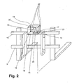
- FIG. 2 shows a fork carriage 3 of a truck according to the invention mounted thereon distance measuring system 13, tilt sensor 14 and RFID transmitter / receiver unit 15.
- a housing 18 is attached via a fastening device 17.
- an RFID transmitting / receiving unit 15 is arranged, which essentially consists of a transmitting and receiving antenna 19 and an electronic unit 20.
- the electronic unit 20 is connected via a cable connection 21 with an evaluation unit arranged in the truck in operative connection and serves for processing the data from or for the antenna 19.
- the transmission of data between the evaluation and the electronic unit 20 by means of a standardized bus protocol, in the present Case via CAN bus, via the cable connection 21.
- sensors 22 of the Entfemungsmesssystems 13 are mounted in the edge region of the housing 18 .
- the sensors 22 are designed as laser sensors which are provided for the transmission and reception of signals and are in operative connection with an electronics unit 23 of the distance measuring system 13 arranged behind the antenna 19.
- the distance signals determined by the sensors 22 are processed in the electronic unit 23 and also transmitted by means of CAN bus via the cable connection 21 to the truck.
- an inclination sensor 14 also arranged behind the antenna 19 is an inclination sensor 14, the measured values of which are likewise transmitted via the cable connection 21 to the industrial truck.
- the power supply of all disposed in the housing 18 components 13, 14, 15 via a common power supply, which is also integrated in the cable 21. This and the use of a bus system, with which the data of the components 13, 14, 15 are transmitted over the same lines, reduces the cabling effort compared to vehicles according to the prior art considerably.
- FIG. 3 shows a fork carriage 3 of a truck according to the invention.
- a fastening device 24 is arranged for functional components.
- the fastening device 24 consists essentially of three attached to the upper cross member 16 of the fork carriage 3 Eyelets 25 with which a retaining rail 26 is screwed.
- the support rail 26 carries a 3D camera 27 and a device 15 for communication with an identification system.
- the communication device 15 is constructed in the same way as in the preceding embodiments, wherein in the housing 18 of the communication device 15 no further functional components are accommodated.
- Both the housing 18 of the communication device 15 and the independent housing 28 of the 3D camera 27 have here not shown guide elements which are mounted and fixed by means of a dovetail guide 29 in the support rail 26.
- the components 15, 27 are connected to each other as in the previous embodiments via a cable 21, which contains both lines for power supply as well as for the transmission of information.
- other components such as, for example, collision warning systems, conventional cameras or barcode scanners can also be fastened to the support rail 26.
- 15 further functional components are arranged in the housing 18 of the communication device.
- Standardized transmission methods with standardized protocols are preferably used because of the associated advantages, such as the use of common and therefore cost-effective components, but cases are also conceivable in which a transmission method adapted to the application is advantageous.
- wired transmission and wireless transmission methods such as wireless methods
- the power supply of the functional components also not via cables, but for example by means of a housing 5, 18 arranged, independent battery.
- the common housing 5, 18 may also be designed in other than the forms shown, this being directed to the requirements of the specific application. Due to the necessary for the communication with RFID transponders permeability to electromagnetic waves, the housing 5, 18 preferably be at least partially formed of a polymer material.
Landscapes
- Engineering & Computer Science (AREA)
- Transportation (AREA)
- Structural Engineering (AREA)
- Civil Engineering (AREA)
- Life Sciences & Earth Sciences (AREA)
- Geology (AREA)
- Mechanical Engineering (AREA)
- Forklifts And Lifting Vehicles (AREA)
- Warehouses Or Storage Devices (AREA)
Description
- Die Erfindung betrifft ein Flurförderzeug mit einem vertikal bewegbaren Lastaufnahmemittel und einer im Bereich des Lastaufnahmemittels angeordneten, aus einer RFID-Sende- und Empfangsantenne und einer Elektronikeinheit bestehenden Vorrichtung zur Kommunikation mit einem von RFID-Transpondem gebildeten Identifikationssystem.
- Flurförderzeuge mit vertikal bewegbarem Lastaufnahmemittel sind in vielen Formen für den innerbetrieblichen Warentransport gebräuchlich. Das Lastaufnahmemittel ist zumeist als Lastgabel ausgeführt und an einem Gabelträger befestigt. Dieser kann zumeist aber auch andere Anbaugeräte, wie beispielsweise eine Fassklammer oder einen Dorn, aufnehmen. Zunehmend werden bei Fturförderzeugen Vorrichtungen zur Kommunikation mit einem Identifikationssystem, insbesondere mit RFID-Transpondem, eingesetzt. Diese Systeme werden bevorzugt im Bereich des Lastaufnahmemittels, also am Gabelträger oder am Anbaugerät, angebracht, da sie sich dadurch möglichst nahe an den auszulesenden Identifikationsmitteln befinden und somit eine weitgehend störungsfreie Kommunikation ermöglicht wird.
- Die Anbringung im Bereich des Lastaufnahmemittels weist jedoch eine Reihe von Nachteilen auf. Insbesondere besteht eine große Gefahr, dass die Kommunikationsvorrichtung beschädigt wird. Um dies zu vermeiden, sind sehr stabile und damit große und schwere Befestigungsvorrichtungen erforderlich. Auch Schutzgehäuse für die Kommunikationsvorrichtung müssen sehr stabil und damit groß und aufwändig ausgeführt sein, insbesondere auch, da diese in wesentlichen Teilen nicht aus Metall gefertigt werden können, welches den Empfang der Kommunikationsvorrichtung stören würde.
- Im Bereich des Lastaufnahmemittels werden häufig weitere Funktionskomponenten angebracht, die dazu dienen, die Sicherheit des Flurförderzeugs zu verbessern oder den Umgang mit der Last zu erleichtern. Dies können beispielsweise Kameras sein, die am Gabelträger oder aber direkt an der Gabelspitze angebracht sind. Auch Kollisionsverhütungssysteme, Entfernungsmesssysteme, die punktuell oder über eine größere Fläche den Abstand des Flurförderzeugs von Hindernissen und Lasten ermitteln, so genannte 3D-Kameras, die über einen weiten Bereich in der Lage sind, die Distanz zu Hindernissen zu ermitteln und damit ein dreidimensionales Abbild der Umgebung im Messbereich zu erstellen, Sensoren zur Ermittlung der Neigung des Hubmastes oder des Lastaufnahmemittels sowie Beschleunigungssensoren sind bevorzugt in diesem Bereich angeordnet. Auch diese Komponenten müssen mittels aufwändiger Gehäuse vor Beschädigung geschützt werden. Da für jede Komponente eine eigenständige Befestigungsvorrichtung vorzusehen ist, ist der Gabelträger oder das Lastaufnahmemittel aufwändig zu fertigen. Das Lastgewicht, das aufgenommen werden kann, reduziert sich um das Gewicht der am Lastaufnahmemittel angebrachten Komponenten, woran deren Gehäuse einen großen Anteil haben. Ist das Lastaufnahmemittel zur Erreichung großer Hubhöhen an einem relativ hohen Hubmast vertikal beweglich geführt, wirkt sich das Gewicht der am Lastaufnahmemittel angebrachten Komponenten zudem nachteilig auf das Schwingungsverhalten des Hubmastes aus.
- Da das Platzangebot im Bereich des Lastaufnahmemittels sehr begrenzt ist, ist es zumeist nicht möglich, alle wünschenswerten Funktionskomponenten in idealer Position anzubringen, so dass entweder auf einige dieser Funktionen verzichtet werden muss oder aber erheblicher Aufwand erforderlich wird, um die Nachteile eines weniger geeigneten Anbringungsorts zu kompensieren. Zudem sind zur Spannungsversorgung sowie zur Übertragung von Signalen der Komponenten aufwändige Verkabelungen erforderlich.
- Aus der
US 2004/0102869 A1 ist ein Flurförderzeug mit einer Vorrichtung zur Kommunikation mit RFID- Transpondem bekannt, die in der von dem Flurförderzeug aufzunehmenden Last angeordnet sind. Die Vorrichtung kann im Bereich eines vertikal bewegbaren Lastaufnahmemittels des Flurförderzeugs angeordnet werden und umfasst eine von einem RFID-Reader gebildete Elektronikeinheit und eine Antenne. Die Antenne ist hierbei getrennt von der Elektronikeinheit an dem Lastaufnahmemittel angeordnet und steht mittels einer Kabelverbindung mit der Elektronikeinheit in Wirkverbindung. Eine derartige getrennte Anordnung der Elektronikeinheit und der Antenne verursacht jedoch für die Vorrichtung zur Kommunikation mit den in der Last angeordneten RFID-Transpondern einen hohen Platzbedarf am Lastaufnahmemittel und zudem einen hohen Bauaufwand. Zudem sind die Elektronikeinheit und die Antenne ungeschützt am Lastaufnahmemittel angeordnet und können somit leicht beschädigt werden. - Der Erfindung liegt daher die Aufgabe zugrunde, ein Flurförderzeug mit einem vertikal bewegbaren Lastaufnahmemittel und einer im Bereich des Lastaufnahmemittels angeordneten, aus einer RFID-Sende- und Empfangsantenne und einer Elektronikeinheit bestehenden Vorrichtung zur Kommunikation mit einem von RFID-Transpondem bestehenden Identifikationssystem zu schaffen, das die oben geschilderten Nachteile des Standes der Technik vermeidet und einen einfachen Aufbau, eine sichere Anbringung der die Sicherheit des Flurförderzeugs verbessernde oder den Umgang mit der Last erleichternde Funktionskomponente und deren einwandfreie Funktion gewährleistet.
- Diese Aufgabe wird erfindungsgemäß dadurch gelöst, dass mindestens eine weitere die Sicherheit des Flurförderzeugs verbessernde oder den Umgang mit der Last erleichternde Funktionskomponente im Bereich des Lastaufnahmemittels angeordnet ist, wobei mindestens eine gemeinsame Befestigungsvorrichtung und/oder mindestens ein gemeinsames Gehäuse zur Aufnahme der Vorrichtung zur Kommunikation mit einem Identifikationssystem und der mindestens einer weiteren Funktionskomponente vorgesehen sind. Indem Befestigungsvorrichtung und/oder Gehäuse gemeinsam genutzt werden, entfällt der Aufwand für verschiedene Gehäuse und/oder Befestigungsvorrichtungen. Das Gewicht der im Bereich des Gabelträgers angebrachten Komponenten inklusive Befestigungsvorrichtungen wird ebenfalls deutlich reduziert.
- In einer besonders vorteilhaften Ausgestaltung der Erfindung umfasst die mindestens eine weitere Komponente mindestens eine Kameraeinheit, insbesondere eine Gabelzinkenkamera. Kameras werden häufig im Bereich des Lastaufnahmemittels angebracht, um der Bedienperson bei schwierigen Ein- und Auslagerungsbedingungen bessere Sicht auf die Last oder den Bereich vor dem Lastaufnahmemittel zu ermöglichen Insbesondere bei Gabelzinkenkameras sind häufig Bereiche des Gehäuses, das an einer Gabelzinke angebracht ist, nicht genutzt, sondern dienen nur zum Schutz der Kabelverbindung zum Flurförderzeug vor Beschädigung. Diese Bereiche sind sehr gut geeignet, um eine Kommunikationsvorrichtung, beispielsweise in Form einer RFID-Antenne, anzubringen.
- In einer weiteren vorteilhaften Ausgestaltung umfasst die mindestens eine weitere Komponente mindestens eine Vorrichtung zur Erfassung von Beschleunigungen. Derartige Vorrichtungen werden ebenfalls häufig im Bereich des Lastaufnahmemittels angebracht. Kommunikationsvorrichtungen, die beispielsweise am Gabelträger angebracht sind, weisen Gehäuse auf, bei denen auf der der Last zugewandten Seite eine relativ großflächige Antenne angeordnet ist. Auf der der Last abgewandten Seite erstreckt sich das Gehäuse beziehungsweise die Befestigungsvorrichtung wesentlich weiter als die Ausdehnung der Antenne, um eine hinreichend sichere Befestigung zu ermöglichen. Dieser ungenutzte Raum bietet Platz für die Anbringung eines Beschleunigungssensors, der keine freie "Sicht" auf die Last benötigt.
- Es ist ebenfalls von Vorteil, wenn die mindestens eine weitere Komponente mindestens eine Vorrichtung zur Erfassung der Neigung eines Hubgerüsts und/oder des Lastaufnahmemittels umfasst. Derartige Vorrichtungen werden ebenfalls häufig im Bereich des Lastaufnahmemittels angebracht. Kommunikationsvorrichtungen, die beispielsweise am Gabelträger angebracht sind, weisen Gehäuse auf, bei denen auf der der Last zugewandten Seite eine relativ großflächige Antenne angeordnet ist. Auf der der Last abgewandten Seite erstreckt sich das Gehäuse beziehungsweise die Befestigungsvorrichtung wesentlich weiter als die Ausdehnung der Antenne, um eine hinreichend sichere Befestigung zu ermöglichen. Dieser ungenutzte Raum bietet Platz für die Anbringung eines Neigungssensors, der keine freie "Sicht" auf die Last benötigt.
- Vorteilhafterweise umfasst die mindestens eine weitere Komponente mindestens eine Vorrichtung zur berührungslosen Entfernungsmessung, insbesondere mittels elektromagnetischer Wellen, vorzugsweise eine Lasereinheit und/oder eine Radareinheit. Derartige Vorrichtungen umfassen zumeist mehrere Sende-und/oder Empfangseinheiten, die selbst zwar relativ kleine Abmessungen aufweisen, aber in gewissen Abständen zueinander angeordnet sein müssen. Kommunikationsvorrichtungen, die beispielsweise am Gabelträger angebracht sind, weisen Gehäuse auf, bei denen auf der der Last zugewandten Seite eine relativ großflächige Antenne angeordnet ist. Insbesondere in den Randbereichen können daher bei nur geringfügig vergrößerten Abmessungen des Gehäuses der Kommunikationsvorrichtung die Sende- und/oder Empfangseinheiten der Entfernungsmessvorrichtung angeordnet werden. Die dazugehörige Auswerteelektronik kann beispielsweise auf der der Last abgewandten Seite der Antenne im Gehäuse angeordnet werden, das sich dort wesentlich weiter erstreckt als die Ausdehnung der Antenne, um eine hinreichend sichere Befestigung zu ermöglichen.
- Es ist ebenfalls zweckmäßig, wenn die mindestens eine weitere Komponente mindestens eine Vorrichtung zur Erfassung dreidimensionaler Objekte, insbesondere mittels Laserstrahlung, umfasst. Derartige Vorrichtungen, die auch als 3D-Kamera bezeichnet werden, werden ebenfalls bevorzugt im Bereich des Gabelträgers angeordnet.
- Vorteilhafterweise umfasst die mindestens eine weitere Komponente mindestens eine Sende- und/oder Empfangseinheit einer Vorrichtung zur Kollisionsvermeidung, insbesondere mittels elektromagnetischer Wellen und/oder Ultraschall, insbesondere eine Lasereinheit und/oder eine Radareinheit. Vorrichtungen zur Kollisionsvermeidung umfassen zumeist mehrere Sende- und/oder Empfangseinheiten, die selbst zwar relativ kleine Abmessungen aufweisen, aber in gewissen Abständen zueinander angeordnet sein müssen. Kommunikationsvorrichtungen, die beispielsweise am Gabelträger angebracht sind, weisen Gehäuse auf, bei denen auf der der Last zugewandten Seite eine relativ großflächige Antenne angeordnet ist. Insbesondere in den Randbereichen können daher bei nur geringfügig vergrößerten Abmessungen des Gehäuses der Kommunikationsvorrichtung beziehungsweise geringfügig verkleinerten Abmessungen der Kommunikationsvorrichtung die Sende- und/oder Empfangseinheiten der Entfemungsmessvorrichtung angeordnet werden. Die dazugehörige Auswerteelektronik kann beispielsweise auf der der Last abgewandten Seite der Antenne im Gehäuse angeordnet werden, das sich dort wesentlich weiter erstreckt als die Ausdehnung der Antenne, um eine hinreichend sichere Befestigung zu ermöglichen.
- Es ist ebenfalls zweckmäßig, wenn die mindestens eine weitere Komponente mindestens eine Vorrichtung zum Auslesen optischer Identifikationsmittel, insbesondere Strichcode-Etiketten, umfasst. Vorrichtungen zum Auslesen optischer Identifikationsmittel werden ebenfalls meist im Bereich des Gabelträgers angeordnet. Häufig werden beide Arten von Identifikationssystemen parallel beziehungsweise alternativ eingesetzt. Durch Kombination der Geräte ist es möglich, die Identifikationsdaten beider Systeme auszulesen.
- Es ist von besonderem Vorteil, wenn die Vorrichtung zur Kommunikation mit dem Identifikationssystem und die mindestens eine weitere Funktionskomponente eine gemeinsame Spannungsversorgung aufweisen. Dadurch wird der Aufwand bei Herstellung und Wartung deutlich reduziert, insbesondere, wenn die Energieversorgung über Kabel von einer Energiequelle im Fahrzeug vorgenommen wird.
- Es ist ebenfalls von besonderem Vorteil, wenn die Vorrichtung zur Kommunikation mit dem Identifikationssystem und die mindestens eine weitere Funktionskomponente gemeinsame Mittel zur Signalübertragung zu weiteren Komponenten des Flurförderzeugs, insbesondere zu einer elektronischen Steuerung, aufweisen. Dadurch wird der Aufwand für Herstellung und Wartung deutlich reduziert. Bei Kabelverbindungen ist dies besonders vorteilhaft, da deren Führung vom beweglichen Gabelträger zum Flurförderzeug besonders aufwändig ist.
- In einer vorteilhaften Weiterbildung der Erfindung sind gemeinsame Mittel zur Signalübertragung zu weiteren Komponenten des Flurförderzeugs als Bus-System, vorzugsweise als CAN-Bus, ausgeführt. Auch große Datenmengen und komplexe Informationen können über ein Bus-System mit geringem Aufwand übertragen werden.
- Weitere Vorteile und Einzelheiten der Erfindung werden im Folgenden anhand des in der Zeichnung dargestellten Ausführungsbeispiels näher erläutert. Gleiche beziehungsweise funktional gleiche Teile sind mit gleichen Bezugszeichen gekennzeichnet. Dabei zeigt
- Figur 1
- eine Gabelzinke eines erfindungsgemäßen Flurförderzeugs mit daran montierter Kamera und RFID-Sende-/Empfangseinheit.
- Figur 2
- einen Gabelträger eines erfindungsgemäßen Flurförderzeugs mit daran montiertem Entfernungsmesssystem, Neigungssensor und RFID-Sende-/Empfangseinheit,
- Figur 3
- einen Gabelträger eines erfindungsgemäßen Flurförderzeugs mit an einer gemeinsamen Befestigungsvorrichtung montierten 3D-Kamera und RFID-Sende-/Empfangseinheit.
-
Figur 1 zeigt eine Gabelzinke 1 mit angedeuteten Querträgern 2 eines Gabelträgers 3. Seitlich an der Gabelzinke 1 befestigt ist eine Gabelzinkenkamera 4, die im Wesentlichen aus einem Gehäuse 5 und einem Kameramodul 6 besteht. Das Gehäuse 5 ist mittels dreier als Schraubverbindungen ausgeführter Befestigungsvorrichtungen 7 an der Gabelzinke 1 befestigt. Das Kameramodul 6 umfasst hier nicht im Detail dargestellte optische und elektronische Komponenten, die zur Erfassung und Aufbereitung der Bildsignale dienen. Der hintere Teil 8 des Gehäuses 5 dient bei Gabelzinkenkameras nach dem Stand der Technik lediglich dazu, das Kabel, das das Kameramodul 6 mit einem Monitor am Fahrerplatz des Flurförderzeugs verbindet, vor Beschädigung zu schützen und ist ansonsten leer. Im gezeigten Ausführungsbeispiel ist im hinteren Teil 8 des Gehäuses 5 eine Vorrichtung 9 zur Kommunikation mit RFID-Transpondem angeordnet. Die Kommunikationsvorrichtung 9 besteht im Wesentlichen aus einer kombinierten RFID-Sende- und Empfangsantenne 10 sowie einer Elektronikeinheit 11, die zur Aufbereitung der RFID-Signale dient. Zur gemeinsamen Energieversorgung sowohl der Kommunikationsvorrichtung 9 als auch des Kameramoduls 6 sind geeignete Leitungen in einem Kabel 12 zusammengefasst. Die benötigte Energie wird dabei je nach Ausführungsform des Flurförderzeugs beispielsweise einer Batterie oder einer Brennstoffzelleneinheit entnommen oder von einem Generator geliefert, der von einem Verbrennungsmotor angetrieben wird. Im gezeigten Ausführungsbeispiel erfolgt die Datenübertragung vom Kameramodul 6 und von der Elektronikeinheit 11 nach einem standardisierten Übertragungsprotokoll über eine gemeinsame Leitung, die ebenfalls im Kabel 12 integriert ist. -
Figur 2 zeigt einen Gabelträger 3 eines erfindungsgemäßen Flurförderzeugs mit daran montiertem Entfernungsmesssystem 13, Neigungssensor 14 und RFID-Sende-/Empfangseinheit 15. An einem oberen Querträger 16 eines Gabelträgers 3 ist über eine Befestigungsvorrichtung 17 ein Gehäuse 18 befestigt. Im Gehäuse 18 ist eine RFID-Sende-/Empfangseinheit 15 angeordnet, die im Wesentlichen aus einer Sende- und Empfangsantenne 19 sowie einer Elektronikeinheit 20 besteht. Die Elektronikeinheit 20 steht über eine Kabelverbindung 21 mit einer im Flurförderzeug angeordneten Auswerteeinheit in Wirkverbindung und dient zur Aufbereitung der Daten von beziehungsweise für die Antenne 19. Die Übertragung der Daten zwischen der Auswerteeinheit und der Elektronikeinheit 20 erfolgt mittels eines standardisierten Bus-Protokolls, im vorliegenden Fall mittels CAN-Bus, über die Kabelverbindung 21. Im Randbereich des Gehäuses 18 sind Sensoren 22 des Entfemungsmesssystems 13 angebracht. Die Sensoren 22 sind als Lasersensoren ausgeführt, die zur Aussendung und zum Empfang von Signalen vorgesehen sind und mit einer hinter der Antenne 19 angeordneten Elektronikeinheit 23 des Entfernungsmesssystems 13 in Wirkverbindung stehen. Die von den Sensoren 22 ermittelten Entfernungssignale werden in der Elektronikeinheit 23 aufbereitet und ebenfalls mittels CAN-Bus über die Kabelverbindung 21 an das Flurförderzeug übertragen. Ebenfalls hinter der Antenne 19 angeordnet ist ein Neigungssensor 14, dessen Messwerte ebenfalls über die Kabelverbindung 21 an das Flurförderzeug übermittelt werden. Die Stromversorgung sämtlicher in dem Gehäuse 18 angeordneter Komponenten 13, 14, 15 erfolgt über eine gemeinsame Stromzuführung, die ebenfalls im Kabel 21 integriert ist. Dadurch und durch die Verwendung eines Bus-Systems, mit dem die Daten der Komponenten 13, 14, 15 über die selben Leitungen übertragen werden, reduziert sich der Verkabelungsaufwand gegenüber Fahrzeugen nach dem Stand der Technik erheblich. -
Figur 3 zeigt einen Gabelträger 3 eines erfindungsgemäßen Flurförderzeugs. Am oberen Querträger 16 des Gabelträgers 3 ist eine Befestigungsvorrichtung 24 für Funktionskomponenten angeordnet. Die Befestigungsvorrichtung 24 besteht im Wesentlichen aus drei am oberen Querträger 16 des Gabelträgers 3 angebrachten Ösen 25, mit denen eine Halteschiene 26 verschraubt ist. Die Halteschiene 26 trägt eine 3D-Kamera 27 und eine Vorrichtung 15 zur Kommunikation mit einem Identifikationssystem. Die Kommunikationsvorrichtung 15 ist in gleicher Weise wie in den vorhergehenden Ausführungsbeispielen aufgebaut, wobei im Gehäuse 18 der Kommunikationsvorrichtung 15 keine weiteren Funktionskomponenten untergebracht sind. Sowohl das Gehäuse 18 der Kommunikationsvorrichtung 15 als auch das eigenständige Gehäuse 28 der 3D-Kamera 27 besitzen hier nicht dargestellte Führungselemente, die mittels einer Schwalbenschwanzführung 29 in der Halteschiene 26 gelagert und fixiert sind. Die Komponenten 15, 27 sind wie in den vorangegangenen Ausführungsbeispielen über ein Kabel 21 miteinander verbunden, das sowohl Leitungen zur Spannungsversorgung als auch zur Übertragung von Informationen enthält. Anstelle der gezeigten Komponenten 15, 27 können an der Halteschiene 26 auch andere Komponenten wie beispielsweise Kollisionswarnsysteme, herkömmliche Kameras oder Barcode-Scanner befestigt werden. Selbstverständlich sind auch Ausführungsformen denkbar, bei denen im Gehäuse 18 der Kommunikationsvorrichtung 15 weitere Funktionskomponenten angeordnet sind. - Selbstverständlich sind auch andere als die gezeigten Ausführungsformen der Erfindung denkbar. So können anstelle der gezeigten Funktionskomponenten 4, 13, 14, 27 auch andere Systeme, wie beispielsweise auf Ultraschall oder Radartechnik beruhende Systeme zur Erkennung von Hindernissen, zur Abstandsmessung oder zur Positionsbestimmung, Sensoren zur Erfassung diverser Messgrößen wie beispielsweise Beschleunigungen, Lastgewicht oder Hubhöhe, sowie Beleuchtungseinrichtungen in einem Gehäuse 5,18 mit der Kommunikationsvorrichtung 9, 15 angeordnet werden beziehungsweise identische Befestigungsvorrichtungen 7, 17, 24, nutzen. Anstelle des in den Ausführungsbeispielen verwendeten CAN-Bus-Systems können selbstverständlich auch andere Datenübertragungsverfahren, die eine Übertragung der Daten mehrerer Komponenten auf dem gleichen Signalweg ermöglichen, verwendet werden, wie beispielsweise LAN, W-LAN, USB, Bluetooth. Standardisierte Übertragungsverfahren mit genormten Protokollen werden wegen der damit verbundenen Vorteile, wie beispielsweise der Verwendung verbreiteter und damit kostengünstiger Komponenten, bevorzugt Verwendung finden, es sind jedoch auch Fälle denkbar, in denen ein an den Anwendungsfall angepasstes Übertragungsverfahren vorteilhaft ist. Neben kabelgebundener Übertragung sind auch kabellose Übertragungsverfahren, wie beispielsweise Funkverfahren, denkbar, insbesondere wenn die Energieversorgung der Funktionskomponenten ebenfalls nicht über Kabel, sondern beispielsweise mittels einer im Gehäuse 5, 18 angeordneten, eigenständigen Batterie erfolgt. Das gemeinsame Gehäuse 5, 18 kann auch in anderen als den gezeigten Formen ausgeführt sein, wobei sich dies nach den Anforderungen des konkreten Anwendungsfalls richtet. Aufgrund der für die Kommunikation mit RFID-Transpondem notwendigen Durchlässigkeit für elektromagnetische Wellen wird das Gehäuse 5, 18 vorzugsweise zumindest teilweise aus einem Polymerwerkstoff gebildet sein.
Claims (11)
- Flurförderzeug mit einem vertikal bewegbaren Lastaufnahmemittel (1) und einer im Bereich des Lastaufnahmemittels (1) angeordneten, aus einer RFID-Sende- und Empfangsantenne (10, 19) und einer Elektronikeinheit (11, 20) bestehenden Vorrichtung (9, 15) zur Kommunikation mit einem von RFID-Transpondem gebildeten Identifikationssystem, dadurch gekennzeichnet, dass mindestens eine weitere die Sicherheit des Flurförderzeugs verbessernde oder den Umgang mit der Last erleichternde Funktionskomponente (4) im Bereich des Lastaufnahmemittels (1) angeordnet ist, wobei mindestens eine gemeinsame Befestigungsvorrichtung (7, 17, 24) und/oder mindestens ein gemeinsames Gehäuse (5, 18) zur Aufnahme der Vorrichtung (9, 15) zur Kommunikation mit dem Identifikationssystem und der mindestens einer weiteren Funktionskomponente (4) vorgesehen ist.
- Flurförderzeug nach Anspruch 1, dadurch gekennzeichnet, dass die mindestens eine weitere Funktionskomponente (4) mindestens eine Kameraeinheit (6), insbesondere eine Gabelzinkenkamera (4), umfasst.
- Flurförderzeug nach Anspruch 1 oder 2, dadurch gekennzeichnet, dass die mindestens eine weitere Funktionskomponente (4) mindestens eine Vorrichtung zur Erfassung von Beschleunigungen umfasst.
- Flurförderzeug nach einem der Ansprüche 1 bis 3, dadurch gekennzeichnet, dass die mindestens eine weitere Funktionskomponente (4) mindestens eine Vorrichtung (14) zur Erfassung der Neigung eines Hubgerüsts und/oder des Lastaufnahmemittels (1) umfasst.
- Flurförderzeug nach einem der Ansprüche 1 bis 3, dadurch gekennzeichnet, dass die mindestens eine weitere Funktionskomponente (4) mindestens eine Vorrichtung zur berührungslosen Entfernungsmessung (13), insbesondere mittels elektromagnetischer Wellen, vorzugsweise eine Lasereinheit (22) und/oder eine Radareinheit, umfasst
- Flurförderzeug nach einem der Ansprüche 1 bis 3, dadurch gekennzeichnet, dass die mindestens eine weitere Funktionskomponente (4) mindestens eine Vorrichtung (27) zur Erfassung dreidimensionaler Objekte, insbesondere mittels Laserstrahlung umfasst.
- Flurförderzeug nach einem der Ansprüche 1 bis 3, dadurch gekennzeichnet, dass die mindestens eine weitere Funktionskomponente (4) mindestens eine Sende- und/oder Empfangseinheit einer Vorrichtung zur Kollisionsvermeidung, insbesondere mittels elektromagnetischer Wellen und/oder Ultraschall, insbesondere eine Lasereinheit und/oder eine Radareinheit, umfasst.
- Flurförderzeug nach einem der Ansprüche 1 bis 3, dadurch gekennzeichnet, dass die mindestens eine weitere Funktionskomponente (4) mindestens eine Vorrichtung zum Auslesen optischer Identifikationsmittel, insbesondere Strichcode-Etiketten, umfasst.
- Flurförderzeug nach einem der Ansprüche 1 bis 3, dadurch gekennzeichnet, dass die Vorrichtung (9, 15) zur Kommunikation mit dem Identifikationssystem und die mindestens eine weitere Funktionskomponente (4) eine gemeinsame Spannungsversorgung (12, 21) aufweisen.
- Flurförderzeug nach einem der Ansprüche 1 bis 3, dadurch gekennzeichnet, dass die Vorrichtung (9, 15) zur Kommunikation mit dem Identifikationssystem und die mindestens eine weitere Funktionskomponente (4) gemeinsame Mittel (21) zur Signalübertragung zu weiteren Funktionskomponenten des Flurförderzeugs, insbesondere zu einer elektronischen Steuerung, aufweisen.
- Flurförderzeug nach einem der Ansprüche 1 bis 3, dadurch gekennzeichnet, dass die gemeinsamen Mittel (21) zur Signalübertragung zu weiteren Funktionskomponenten des Flurförderzeugs als Bus-System, vorzugsweise als CAN-Bus, ausgeführt sind.
Applications Claiming Priority (1)
| Application Number | Priority Date | Filing Date | Title |
|---|---|---|---|
| DE102005024882A DE102005024882A1 (de) | 2005-05-31 | 2005-05-31 | Flurförderzeug |
Publications (2)
| Publication Number | Publication Date |
|---|---|
| EP1728757A1 EP1728757A1 (de) | 2006-12-06 |
| EP1728757B1 true EP1728757B1 (de) | 2011-09-07 |
Family
ID=36791733
Family Applications (1)
| Application Number | Title | Priority Date | Filing Date |
|---|---|---|---|
| EP06008815A Not-in-force EP1728757B1 (de) | 2005-05-31 | 2006-04-27 | Flurförderzeug |
Country Status (3)
| Country | Link |
|---|---|
| EP (1) | EP1728757B1 (de) |
| AT (1) | ATE523463T1 (de) |
| DE (1) | DE102005024882A1 (de) |
Cited By (3)
| Publication number | Priority date | Publication date | Assignee | Title |
|---|---|---|---|---|
| US9658622B2 (en) | 2015-05-06 | 2017-05-23 | Crown Equipment Corporation | Industrial vehicle for identifying malfunctioning sequenced tag and tag layout for use therewith |
| US9818003B2 (en) | 2015-05-06 | 2017-11-14 | Crown Equipment Corporation | Diagnostic tag for an industrial vehicle tag reader |
| EP3453672A1 (de) | 2017-09-12 | 2019-03-13 | STILL GmbH | Verfahren und vorrichtung zur kollisionsvermeidung beim betrieb eines flurförderzeugs |
Families Citing this family (12)
| Publication number | Priority date | Publication date | Assignee | Title |
|---|---|---|---|---|
| DE102007061707A1 (de) * | 2007-12-19 | 2009-06-25 | Technische Universität München | Flurförderzeug mit einer RFID-gestützten Einrichtung zur Identifikation von Ladungsgütern |
| EP2184254B1 (de) * | 2008-11-11 | 2013-01-09 | Deutsche Post AG | Gabelstapler mit Führungs- und Kollisionswarnvorrichtung |
| DE102009004742A1 (de) * | 2009-01-15 | 2010-07-22 | Jungheinrich Ag | Gabelzinke für eine Lastgabel eines Flurförderzeugs |
| DE202010012161U1 (de) | 2010-09-02 | 2011-01-05 | Sae Schaarschmidt Analytic Engineering Gmbh | Flurförderfahrzeug |
| DE102011082273A1 (de) * | 2011-09-07 | 2013-03-07 | Jungheinrich Aktiengesellschaft | Gewerbliches Fahrzeug mit in Richtung nach oben sensierendem Radarsensor |
| GB2494884B (en) * | 2011-09-21 | 2016-01-20 | Palletforce Plc | Apparatus and method for the identification and weighing of cargo |
| DE102014117339A1 (de) * | 2014-11-26 | 2016-06-02 | Still Gmbh | Transponderlesemodul für Gabelschuh |
| DE102016208350A1 (de) * | 2016-05-13 | 2017-11-16 | Vetter Industrie GmbH | Heb- und senkbares Lastaufnahmemittel |
| DE102017120998A1 (de) | 2017-09-12 | 2019-03-14 | Still Gmbh | Verfahren und Vorrichtung zur Kalibrierung eines optischen Sensors an einem Flurförderzeug |
| DE102019120021A1 (de) * | 2019-07-24 | 2021-01-28 | Jungheinrich Aktiengesellschaft | Flurförderzeug mit einer Assistenzeinrichtung |
| DE102019132375A1 (de) * | 2019-11-27 | 2021-05-27 | Rogama B.V. | Lastaufnahmemittel |
| CN113280855B (zh) * | 2021-04-30 | 2022-07-26 | 中国船舶重工集团公司第七一三研究所 | 一种多源传感货叉智能感知系统及方法 |
Family Cites Families (4)
| Publication number | Priority date | Publication date | Assignee | Title |
|---|---|---|---|---|
| JPH10231096A (ja) * | 1997-02-19 | 1998-09-02 | Toyota Autom Loom Works Ltd | フォークリフトトラックの安全システム |
| JP2000226199A (ja) * | 1999-02-04 | 2000-08-15 | Nippon Yusoki Co Ltd | フォ−クリフト |
| US7151979B2 (en) * | 2002-11-26 | 2006-12-19 | International Paper Company | System and method for tracking inventory |
| JP4298453B2 (ja) * | 2003-09-30 | 2009-07-22 | 住友ナコ マテリアル ハンドリング株式会社 | 荷役補助装置、及び、監視装置 |
-
2005
- 2005-05-31 DE DE102005024882A patent/DE102005024882A1/de not_active Withdrawn
-
2006
- 2006-04-27 EP EP06008815A patent/EP1728757B1/de not_active Not-in-force
- 2006-04-27 AT AT06008815T patent/ATE523463T1/de active
Cited By (10)
| Publication number | Priority date | Publication date | Assignee | Title |
|---|---|---|---|---|
| US9658622B2 (en) | 2015-05-06 | 2017-05-23 | Crown Equipment Corporation | Industrial vehicle for identifying malfunctioning sequenced tag and tag layout for use therewith |
| US9811088B2 (en) | 2015-05-06 | 2017-11-07 | Crown Equipment Corporation | Industrial vehicle comprising tag reader and reader module |
| US9818003B2 (en) | 2015-05-06 | 2017-11-14 | Crown Equipment Corporation | Diagnostic tag for an industrial vehicle tag reader |
| US10515237B2 (en) | 2015-05-06 | 2019-12-24 | Crown Equipment Corporation | Tag reader with diagnostic tag and an industrial vehicle incorporating the same |
| US11288463B2 (en) | 2015-05-06 | 2022-03-29 | Crown Equipment Corporation | Tag reader with diagnostic tag |
| US11726496B2 (en) | 2015-05-06 | 2023-08-15 | Crown Equipment Corporation | Tag layout for industrial vehicle operation |
| US11797785B2 (en) | 2015-05-06 | 2023-10-24 | Crown Equipment Corporation | Tag reader with diagnostic tag |
| US12093056B2 (en) | 2015-05-06 | 2024-09-17 | Crown Equipment Corporation | Tag layout for industrial vehicle operation |
| US12429884B2 (en) | 2015-05-06 | 2025-09-30 | Crown Equipment Corporation | Tag layout for industrial vehicle operation |
| EP3453672A1 (de) | 2017-09-12 | 2019-03-13 | STILL GmbH | Verfahren und vorrichtung zur kollisionsvermeidung beim betrieb eines flurförderzeugs |
Also Published As
| Publication number | Publication date |
|---|---|
| ATE523463T1 (de) | 2011-09-15 |
| DE102005024882A1 (de) | 2006-12-07 |
| EP1728757A1 (de) | 2006-12-06 |
Similar Documents
| Publication | Publication Date | Title |
|---|---|---|
| EP1728757B1 (de) | Flurförderzeug | |
| EP2321175B1 (de) | Beladungssystem und verfahren zum beladen eines laderaums eines flugzeugs | |
| DE202010008162U1 (de) | RFID-Lesevorrichtung | |
| EP2208704B1 (de) | Gabelzinke für eine Lastgabel eines Flurförderzeugs | |
| EP2741230B1 (de) | RFID-Lesetunnel zur Identifizierung von Objekten mittels RFID | |
| EP2012253B1 (de) | Auslesen von Informationen mit optoelektronischem Sensor und RFID-Leser | |
| EP1840078A1 (de) | Flurförderzeug mit einem Datenbus und einer Sende- und Empfangseinheit | |
| EP1767471B1 (de) | System zur Erkennung und Verwaltung von Paletten | |
| DE102013004537A1 (de) | Vorrichtung und Verfahren zur Ladungsüberwachung | |
| EP1767488B1 (de) | System zur Unterstützung eines Fahrers eines Flurförderzeugs während der Fahrt | |
| EP3034452B1 (de) | System aus gabelschuh und zumindest zwei modulen, die jeweils ein abweichendes einbaugerät enthalten | |
| EP0668236A1 (de) | Anordnung zur Lastpositionierung bei Kranen | |
| DE102004001198A1 (de) | Verfahren zur Überwachung des Lagerzustandes mittels einem sehenden autonomen Transportfahrzeug | |
| EP1710203A1 (de) | Flurförderzeug mit einem Lastaufnahmemittel | |
| DE102010047630A1 (de) | Gabelschuh | |
| EP3162753B1 (de) | Energieversorgungseinheit eines zusatzgerätes an einer lastaufnahmevorrichtung eines flurförderzeugs | |
| DE102011005610A1 (de) | Verfahren und System zur Überwachung von Gegenständen | |
| DE102017219668A1 (de) | Verfahren und Anordnung zum Erkennen eines Schadensereignisses an einem Lagerregal | |
| EP3273382B1 (de) | Rfid-lesevorrichtung und verfahren zur fachbelegungserkennung in einem regal | |
| EP4091062B1 (de) | Sensormodul für ein mobilteil, mobilteil und anlage | |
| DE102007038366B4 (de) | Verfahren und Vorrichtung zur Ansteuerung von Precrash-Mitteln in einem Kraftfahrzeug | |
| DE102023002384A1 (de) | Verfahren zum Betreiben einer technischen Anlage und technische Anlage | |
| DE102014117341A1 (de) | Flurförderzeug mit RFID-Sender/Empfänger | |
| DE102005033337A1 (de) | Fahrzeug mit einem Transponder | |
| EP2686811B1 (de) | Bauwerkszugangsvorrichtung sowie bauelement hierfür |
Legal Events
| Date | Code | Title | Description |
|---|---|---|---|
| PUAI | Public reference made under article 153(3) epc to a published international application that has entered the european phase |
Free format text: ORIGINAL CODE: 0009012 |
|
| AK | Designated contracting states |
Kind code of ref document: A1 Designated state(s): AT BE BG CH CY CZ DE DK EE ES FI FR GB GR HU IE IS IT LI LT LU LV MC NL PL PT RO SE SI SK TR |
|
| AX | Request for extension of the european patent |
Extension state: AL BA HR MK YU |
|
| 17P | Request for examination filed |
Effective date: 20061114 |
|
| 17Q | First examination report despatched |
Effective date: 20070131 |
|
| AKX | Designation fees paid |
Designated state(s): AT BE BG CH CY CZ DE DK EE ES FI FR GB GR HU IE IS IT LI LT LU LV MC NL PL PT RO SE SI SK TR |
|
| GRAP | Despatch of communication of intention to grant a patent |
Free format text: ORIGINAL CODE: EPIDOSNIGR1 |
|
| GRAS | Grant fee paid |
Free format text: ORIGINAL CODE: EPIDOSNIGR3 |
|
| GRAA | (expected) grant |
Free format text: ORIGINAL CODE: 0009210 |
|
| REG | Reference to a national code |
Ref country code: GB Ref legal event code: FG4D Free format text: NOT ENGLISH |
|
| REG | Reference to a national code |
Ref country code: CH Ref legal event code: EP |
|
| REG | Reference to a national code |
Ref country code: IE Ref legal event code: FG4D Free format text: LANGUAGE OF EP DOCUMENT: GERMAN |
|
| REG | Reference to a national code |
Ref country code: DE Ref legal event code: R096 Ref document number: 502006010096 Country of ref document: DE Effective date: 20111103 |
|
| REG | Reference to a national code |
Ref country code: NL Ref legal event code: VDEP Effective date: 20110907 |
|
| PG25 | Lapsed in a contracting state [announced via postgrant information from national office to epo] |
Ref country code: FI Free format text: LAPSE BECAUSE OF FAILURE TO SUBMIT A TRANSLATION OF THE DESCRIPTION OR TO PAY THE FEE WITHIN THE PRESCRIBED TIME-LIMIT Effective date: 20110907 Ref country code: SE Free format text: LAPSE BECAUSE OF FAILURE TO SUBMIT A TRANSLATION OF THE DESCRIPTION OR TO PAY THE FEE WITHIN THE PRESCRIBED TIME-LIMIT Effective date: 20110907 Ref country code: LT Free format text: LAPSE BECAUSE OF FAILURE TO SUBMIT A TRANSLATION OF THE DESCRIPTION OR TO PAY THE FEE WITHIN THE PRESCRIBED TIME-LIMIT Effective date: 20110907 |
|
| LTIE | Lt: invalidation of european patent or patent extension |
Effective date: 20110907 |
|
| PG25 | Lapsed in a contracting state [announced via postgrant information from national office to epo] |
Ref country code: GR Free format text: LAPSE BECAUSE OF FAILURE TO SUBMIT A TRANSLATION OF THE DESCRIPTION OR TO PAY THE FEE WITHIN THE PRESCRIBED TIME-LIMIT Effective date: 20111208 Ref country code: LV Free format text: LAPSE BECAUSE OF FAILURE TO SUBMIT A TRANSLATION OF THE DESCRIPTION OR TO PAY THE FEE WITHIN THE PRESCRIBED TIME-LIMIT Effective date: 20110907 Ref country code: CY Free format text: LAPSE BECAUSE OF FAILURE TO SUBMIT A TRANSLATION OF THE DESCRIPTION OR TO PAY THE FEE WITHIN THE PRESCRIBED TIME-LIMIT Effective date: 20110907 Ref country code: SI Free format text: LAPSE BECAUSE OF FAILURE TO SUBMIT A TRANSLATION OF THE DESCRIPTION OR TO PAY THE FEE WITHIN THE PRESCRIBED TIME-LIMIT Effective date: 20110907 |
|
| REG | Reference to a national code |
Ref country code: IE Ref legal event code: FD4D |
|
| PG25 | Lapsed in a contracting state [announced via postgrant information from national office to epo] |
Ref country code: CZ Free format text: LAPSE BECAUSE OF FAILURE TO SUBMIT A TRANSLATION OF THE DESCRIPTION OR TO PAY THE FEE WITHIN THE PRESCRIBED TIME-LIMIT Effective date: 20110907 Ref country code: SK Free format text: LAPSE BECAUSE OF FAILURE TO SUBMIT A TRANSLATION OF THE DESCRIPTION OR TO PAY THE FEE WITHIN THE PRESCRIBED TIME-LIMIT Effective date: 20110907 Ref country code: IS Free format text: LAPSE BECAUSE OF FAILURE TO SUBMIT A TRANSLATION OF THE DESCRIPTION OR TO PAY THE FEE WITHIN THE PRESCRIBED TIME-LIMIT Effective date: 20120107 Ref country code: IE Free format text: LAPSE BECAUSE OF FAILURE TO SUBMIT A TRANSLATION OF THE DESCRIPTION OR TO PAY THE FEE WITHIN THE PRESCRIBED TIME-LIMIT Effective date: 20110907 |
|
| PG25 | Lapsed in a contracting state [announced via postgrant information from national office to epo] |
Ref country code: PL Free format text: LAPSE BECAUSE OF FAILURE TO SUBMIT A TRANSLATION OF THE DESCRIPTION OR TO PAY THE FEE WITHIN THE PRESCRIBED TIME-LIMIT Effective date: 20110907 Ref country code: RO Free format text: LAPSE BECAUSE OF FAILURE TO SUBMIT A TRANSLATION OF THE DESCRIPTION OR TO PAY THE FEE WITHIN THE PRESCRIBED TIME-LIMIT Effective date: 20110907 Ref country code: NL Free format text: LAPSE BECAUSE OF FAILURE TO SUBMIT A TRANSLATION OF THE DESCRIPTION OR TO PAY THE FEE WITHIN THE PRESCRIBED TIME-LIMIT Effective date: 20110907 Ref country code: IT Free format text: LAPSE BECAUSE OF FAILURE TO SUBMIT A TRANSLATION OF THE DESCRIPTION OR TO PAY THE FEE WITHIN THE PRESCRIBED TIME-LIMIT Effective date: 20110907 Ref country code: EE Free format text: LAPSE BECAUSE OF FAILURE TO SUBMIT A TRANSLATION OF THE DESCRIPTION OR TO PAY THE FEE WITHIN THE PRESCRIBED TIME-LIMIT Effective date: 20110907 Ref country code: PT Free format text: LAPSE BECAUSE OF FAILURE TO SUBMIT A TRANSLATION OF THE DESCRIPTION OR TO PAY THE FEE WITHIN THE PRESCRIBED TIME-LIMIT Effective date: 20120109 |
|
| PLBE | No opposition filed within time limit |
Free format text: ORIGINAL CODE: 0009261 |
|
| STAA | Information on the status of an ep patent application or granted ep patent |
Free format text: STATUS: NO OPPOSITION FILED WITHIN TIME LIMIT |
|
| PG25 | Lapsed in a contracting state [announced via postgrant information from national office to epo] |
Ref country code: DK Free format text: LAPSE BECAUSE OF FAILURE TO SUBMIT A TRANSLATION OF THE DESCRIPTION OR TO PAY THE FEE WITHIN THE PRESCRIBED TIME-LIMIT Effective date: 20110907 |
|
| 26N | No opposition filed |
Effective date: 20120611 |
|
| REG | Reference to a national code |
Ref country code: DE Ref legal event code: R097 Ref document number: 502006010096 Country of ref document: DE Effective date: 20120611 |
|
| BERE | Be: lapsed |
Owner name: STILL G.M.B.H. Effective date: 20120430 |
|
| PG25 | Lapsed in a contracting state [announced via postgrant information from national office to epo] |
Ref country code: MC Free format text: LAPSE BECAUSE OF NON-PAYMENT OF DUE FEES Effective date: 20120430 |
|
| REG | Reference to a national code |
Ref country code: CH Ref legal event code: PL |
|
| PG25 | Lapsed in a contracting state [announced via postgrant information from national office to epo] |
Ref country code: BE Free format text: LAPSE BECAUSE OF NON-PAYMENT OF DUE FEES Effective date: 20120430 Ref country code: CH Free format text: LAPSE BECAUSE OF NON-PAYMENT OF DUE FEES Effective date: 20120430 Ref country code: LI Free format text: LAPSE BECAUSE OF NON-PAYMENT OF DUE FEES Effective date: 20120430 |
|
| PG25 | Lapsed in a contracting state [announced via postgrant information from national office to epo] |
Ref country code: ES Free format text: LAPSE BECAUSE OF FAILURE TO SUBMIT A TRANSLATION OF THE DESCRIPTION OR TO PAY THE FEE WITHIN THE PRESCRIBED TIME-LIMIT Effective date: 20111218 |
|
| REG | Reference to a national code |
Ref country code: AT Ref legal event code: MM01 Ref document number: 523463 Country of ref document: AT Kind code of ref document: T Effective date: 20120427 |
|
| PG25 | Lapsed in a contracting state [announced via postgrant information from national office to epo] |
Ref country code: BG Free format text: LAPSE BECAUSE OF FAILURE TO SUBMIT A TRANSLATION OF THE DESCRIPTION OR TO PAY THE FEE WITHIN THE PRESCRIBED TIME-LIMIT Effective date: 20111207 |
|
| PG25 | Lapsed in a contracting state [announced via postgrant information from national office to epo] |
Ref country code: AT Free format text: LAPSE BECAUSE OF NON-PAYMENT OF DUE FEES Effective date: 20120427 |
|
| PG25 | Lapsed in a contracting state [announced via postgrant information from national office to epo] |
Ref country code: TR Free format text: LAPSE BECAUSE OF FAILURE TO SUBMIT A TRANSLATION OF THE DESCRIPTION OR TO PAY THE FEE WITHIN THE PRESCRIBED TIME-LIMIT Effective date: 20110907 |
|
| PG25 | Lapsed in a contracting state [announced via postgrant information from national office to epo] |
Ref country code: LU Free format text: LAPSE BECAUSE OF NON-PAYMENT OF DUE FEES Effective date: 20120427 |
|
| PG25 | Lapsed in a contracting state [announced via postgrant information from national office to epo] |
Ref country code: HU Free format text: LAPSE BECAUSE OF FAILURE TO SUBMIT A TRANSLATION OF THE DESCRIPTION OR TO PAY THE FEE WITHIN THE PRESCRIBED TIME-LIMIT Effective date: 20060427 |
|
| REG | Reference to a national code |
Ref country code: FR Ref legal event code: PLFP Year of fee payment: 10 |
|
| PGFP | Annual fee paid to national office [announced via postgrant information from national office to epo] |
Ref country code: GB Payment date: 20150423 Year of fee payment: 10 Ref country code: DE Payment date: 20150422 Year of fee payment: 10 |
|
| PGFP | Annual fee paid to national office [announced via postgrant information from national office to epo] |
Ref country code: FR Payment date: 20150422 Year of fee payment: 10 |
|
| REG | Reference to a national code |
Ref country code: DE Ref legal event code: R119 Ref document number: 502006010096 Country of ref document: DE |
|
| GBPC | Gb: european patent ceased through non-payment of renewal fee |
Effective date: 20160427 |
|
| REG | Reference to a national code |
Ref country code: DE Ref legal event code: R082 Ref document number: 502006010096 Country of ref document: DE Representative=s name: PATENTSHIP PATENTANWALTSGESELLSCHAFT MBH, DE |
|
| REG | Reference to a national code |
Ref country code: FR Ref legal event code: ST Effective date: 20161230 |
|
| PG25 | Lapsed in a contracting state [announced via postgrant information from national office to epo] |
Ref country code: DE Free format text: LAPSE BECAUSE OF NON-PAYMENT OF DUE FEES Effective date: 20161101 Ref country code: GB Free format text: LAPSE BECAUSE OF NON-PAYMENT OF DUE FEES Effective date: 20160427 Ref country code: FR Free format text: LAPSE BECAUSE OF NON-PAYMENT OF DUE FEES Effective date: 20160502 |
|
| REG | Reference to a national code |
Ref country code: DE Ref legal event code: R082 Ref document number: 502006010096 Country of ref document: DE Representative=s name: PATENTSHIP PATENTANWALTSGESELLSCHAFT MBH, DE |