EP1728215B1 - Beam-hardening and attenuation correction for coherent-scatter computed tomography (csct) - Google Patents
Beam-hardening and attenuation correction for coherent-scatter computed tomography (csct) Download PDFInfo
- Publication number
- EP1728215B1 EP1728215B1 EP05709011A EP05709011A EP1728215B1 EP 1728215 B1 EP1728215 B1 EP 1728215B1 EP 05709011 A EP05709011 A EP 05709011A EP 05709011 A EP05709011 A EP 05709011A EP 1728215 B1 EP1728215 B1 EP 1728215B1
- Authority
- EP
- European Patent Office
- Prior art keywords
- radiation
- data
- scatter
- interest
- detector
- Prior art date
- Legal status (The legal status is an assumption and is not a legal conclusion. Google has not performed a legal analysis and makes no representation as to the accuracy of the status listed.)
- Not-in-force
Links
- 238000002591 computed tomography Methods 0.000 title claims description 24
- 238000012937 correction Methods 0.000 title abstract description 6
- 230000005855 radiation Effects 0.000 claims abstract description 124
- 238000000034 method Methods 0.000 claims description 34
- 239000000463 material Substances 0.000 claims description 27
- 230000001427 coherent effect Effects 0.000 claims description 20
- 238000001228 spectrum Methods 0.000 claims description 18
- 238000010521 absorption reaction Methods 0.000 claims description 11
- 238000012545 processing Methods 0.000 claims description 9
- 238000004590 computer program Methods 0.000 claims description 6
- 238000000862 absorption spectrum Methods 0.000 claims description 4
- 230000015654 memory Effects 0.000 claims description 3
- XLYOFNOQVPJJNP-UHFFFAOYSA-N water Substances O XLYOFNOQVPJJNP-UHFFFAOYSA-N 0.000 abstract description 14
- 230000006870 function Effects 0.000 description 16
- 230000000694 effects Effects 0.000 description 12
- 238000005259 measurement Methods 0.000 description 12
- 238000004364 calculation method Methods 0.000 description 11
- 238000012546 transfer Methods 0.000 description 6
- 238000007689 inspection Methods 0.000 description 5
- 230000003595 spectral effect Effects 0.000 description 5
- 238000004458 analytical method Methods 0.000 description 4
- 239000002360 explosive Substances 0.000 description 4
- 239000000126 substance Substances 0.000 description 4
- 210000001519 tissue Anatomy 0.000 description 4
- 210000000988 bone and bone Anatomy 0.000 description 3
- 238000002059 diagnostic imaging Methods 0.000 description 3
- 238000003384 imaging method Methods 0.000 description 3
- 238000003325 tomography Methods 0.000 description 3
- MARUHZGHZWCEQU-UHFFFAOYSA-N 5-phenyl-2h-tetrazole Chemical compound C1=CC=CC=C1C1=NNN=N1 MARUHZGHZWCEQU-UHFFFAOYSA-N 0.000 description 2
- 241000446313 Lamella Species 0.000 description 2
- 238000002441 X-ray diffraction Methods 0.000 description 2
- 238000002083 X-ray spectrum Methods 0.000 description 2
- 239000004411 aluminium Substances 0.000 description 2
- XAGFODPZIPBFFR-UHFFFAOYSA-N aluminium Chemical compound [Al] XAGFODPZIPBFFR-UHFFFAOYSA-N 0.000 description 2
- 229910052782 aluminium Inorganic materials 0.000 description 2
- 230000005540 biological transmission Effects 0.000 description 2
- 238000004422 calculation algorithm Methods 0.000 description 2
- 230000001419 dependent effect Effects 0.000 description 2
- 238000001514 detection method Methods 0.000 description 2
- 238000009659 non-destructive testing Methods 0.000 description 2
- 239000004926 polymethyl methacrylate Substances 0.000 description 2
- 229910004611 CdZnTe Inorganic materials 0.000 description 1
- 229920005479 Lucite® Polymers 0.000 description 1
- 238000013459 approach Methods 0.000 description 1
- 238000006243 chemical reaction Methods 0.000 description 1
- 238000003745 diagnosis Methods 0.000 description 1
- 238000005315 distribution function Methods 0.000 description 1
- 238000013213 extrapolation Methods 0.000 description 1
- 239000004744 fabric Substances 0.000 description 1
- 230000012447 hatching Effects 0.000 description 1
- 239000000383 hazardous chemical Substances 0.000 description 1
- 230000010354 integration Effects 0.000 description 1
- 238000013507 mapping Methods 0.000 description 1
- 230000000149 penetrating effect Effects 0.000 description 1
- 229920003229 poly(methyl methacrylate) Polymers 0.000 description 1
- 238000002407 reforming Methods 0.000 description 1
- 238000004088 simulation Methods 0.000 description 1
- WFKWXMTUELFFGS-UHFFFAOYSA-N tungsten Chemical compound [W] WFKWXMTUELFFGS-UHFFFAOYSA-N 0.000 description 1
- 229910052721 tungsten Inorganic materials 0.000 description 1
- 239000010937 tungsten Substances 0.000 description 1
- 230000003936 working memory Effects 0.000 description 1
Images


Classifications
-
- G—PHYSICS
- G01—MEASURING; TESTING
- G01T—MEASUREMENT OF NUCLEAR OR X-RADIATION
- G01T1/00—Measuring X-radiation, gamma radiation, corpuscular radiation, or cosmic radiation
- G01T1/16—Measuring radiation intensity
- G01T1/161—Applications in the field of nuclear medicine, e.g. in vivo counting
- G01T1/164—Scintigraphy
- G01T1/1641—Static instruments for imaging the distribution of radioactivity in one or two dimensions using one or several scintillating elements; Radio-isotope cameras
- G01T1/1647—Processing of scintigraphic data
-
- A—HUMAN NECESSITIES
- A61—MEDICAL OR VETERINARY SCIENCE; HYGIENE
- A61B—DIAGNOSIS; SURGERY; IDENTIFICATION
- A61B6/00—Apparatus or devices for radiation diagnosis; Apparatus or devices for radiation diagnosis combined with radiation therapy equipment
- A61B6/02—Arrangements for diagnosis sequentially in different planes; Stereoscopic radiation diagnosis
- A61B6/03—Computed tomography [CT]
- A61B6/032—Transmission computed tomography [CT]
-
- A—HUMAN NECESSITIES
- A61—MEDICAL OR VETERINARY SCIENCE; HYGIENE
- A61B—DIAGNOSIS; SURGERY; IDENTIFICATION
- A61B6/00—Apparatus or devices for radiation diagnosis; Apparatus or devices for radiation diagnosis combined with radiation therapy equipment
- A61B6/48—Diagnostic techniques
- A61B6/483—Diagnostic techniques involving scattered radiation
-
- G—PHYSICS
- G06—COMPUTING; CALCULATING OR COUNTING
- G06T—IMAGE DATA PROCESSING OR GENERATION, IN GENERAL
- G06T11/00—2D [Two Dimensional] image generation
- G06T11/003—Reconstruction from projections, e.g. tomography
- G06T11/005—Specific pre-processing for tomographic reconstruction, e.g. calibration, source positioning, rebinning, scatter correction, retrospective gating
-
- A—HUMAN NECESSITIES
- A61—MEDICAL OR VETERINARY SCIENCE; HYGIENE
- A61B—DIAGNOSIS; SURGERY; IDENTIFICATION
- A61B6/00—Apparatus or devices for radiation diagnosis; Apparatus or devices for radiation diagnosis combined with radiation therapy equipment
- A61B6/50—Apparatus or devices for radiation diagnosis; Apparatus or devices for radiation diagnosis combined with radiation therapy equipment specially adapted for specific body parts; specially adapted for specific clinical applications
- A61B6/505—Apparatus or devices for radiation diagnosis; Apparatus or devices for radiation diagnosis combined with radiation therapy equipment specially adapted for specific body parts; specially adapted for specific clinical applications for diagnosis of bone
Definitions
- the present invention relates to the field of coherent-scatter computed tomography (CSCT), where a fan-beam is applied to an object of interest.
- CSCT coherent-scatter computed tomography
- the present invention relates to a method of reconstructing coherent-scatter computed tomography data of an object of interest, to a coherent-scatter computed tomography apparatus, to a data processing device for reconstructing coherent-scatter computed tomography data and to a computer program for reconstructing coherent-scatter computed tomography data.
- US 4,751,722 describes a device based on the principle of registration of an angled distribution of coherent scattered radiation within angles of 1° to 12° as related to the direction of the beam.
- the main fraction of elastic scattered radiation is concentrated within angles of less than 12° for photon energies >40 keV, and the scattered radiation has a characteristic angle dependency with well marked maxima, the positions of which are determined by the irradiated substance itself.
- the distribution of the intensity of the coherently scattered radiation in small angles depends on the molecular structure of the substance, different substances having equal absorption capacity (which cannot be differentiated with conventional transillumination or CT) can be distinguished according to the distribution of the intensity of the angled scattering of coherent radiation typical for each substance.
- coherent scatter computer tomography is in principle a sensitive technique for imaging spatial variations in the molecular structure of tissues or other materials across a 2D object section.
- EXDT energy dispersive x-ray diffraction tomograph
- EXDT Due to the use of the pencil beam in combination with only one detector element, only a limited number of photons emitted by the source of radiation and thus only a reduced amount of information can be measured. In case EXDT is applied to larger objects such as for example to pieces of baggage, EXDT has to be used in a scanning mode thus causing extremely long measurement times.
- polychromatic x-ray sources are used as radiation sources.
- No exact reconstruction of a scattering function for a voxel is known for polychromatic primary radiation as emitted from such polychromatic x-ray sources.
- a scattering angle for a given momentum transfer depends on the energy of the scattered photon and the signal structure measured on the respective scatter radiation detector is then a function of superimposed scatter projections for the different energies weighted with the intensity and the energy-dependent attenuation-
- an average energy of the spectrum may be used and then, a monochromatic reconstruction may be applied by using this average energy.
- this may cause a smearing of the scatter function due to the spectrum distribution of the primary radiation.
- the scatter radiation data is compensated for beam-hardening effects. This may reduce a smearing of the reconstructed scatter function. Furthermore, this may enable a quasi-exact determination of the back-projection paths by taking into account the beam-hardening effect.
- a CT reconstruction is performed prior to the CSCT reconstruction. This advantageously allows for a quasi-exact calculation of the back-projection path (of materials occurring on these paths) by taking into account, the beam-hardening effect on the average energy of the scattered photons.
- materials are determined located on a path of a scattered photon of the scatter radiation. This is done on the basis of the CT reconstruction. Then, for performing a correction or compensation of the scatter radiation data, these materials are taken into account and beam-hardening effects and in particular absorption effects may be compensated for in the scatter radiation data. A CSCT reconstruction is then performed on the basis of the corrected scatter radiation data.
- a coherent-scatter computed tomography apparatus where a beam-hardening compensation of scatter radiation data is performed.
- this coherent-scatter computed tomography apparatus may be part of a cone-beam CT system. Due to the described reconstruction according to the present invention which may allow for an improved image quality, this apparatus may advantageously be used in medical imaging for material analysis and, for example, for baggage inspection. Advantageously, for these applications a good resolution of the scatter function which may be achieved with the apparatus according to the present invention is important.
- a data processing device comprising a memory and a data processor.
- the data processing device according to this exemplary embodiment is adapted to perform the method of the present invention.
- a software program for reconstructing coherent-scatter computed tomography data of an object of interest wherein, when the computer software is executed on one of the data processor and a coherent-scatter computed tomography apparatus, an operation in accordance with the method of the present invention is performed.
- the computer program according to the present invention may be stored on a computer readable medium, such as a CD-ROM.
- the computer program may also be presented over a network such as the WorldWideWeb and may be downloaded into the working memory of a data processor from such a network.
- the computer program may be written in any suitable programming language, such as C++.
- a beam-hardening compensation is performed on the scatter radiation data before the scatter radiation data is used for reconstruction. This may allow for a very good spectral resolution of reconstructed scatter functions and may allow to obtain an improved image quality.
- Fig. 1 shows an exemplary embodiment of a computer-tomograph according to the present invention.
- the present invention will be described for the application in baggage inspection, for example to detect hazardous materials, such as explosives, in items of baggage.
- the present invention is not limited to the fields of baggage inspection, but can also be used in other industrial or medical applications, such as, for example, in bone imaging or discrimination of tissue types in medical applications.
- the present invention may be used in the field of non-destructive testing.
- the computer-tomograph depicted in Fig. 1 comprises a gantry 1, which is rotatable around a rotational axis 2.
- the gantry 1 is driven by means of a motor 3.
- Reference character 4 designates the source of radiation, such as an x-ray source which, according to an aspect of the present invention, emits polychromatic radiation.
- Reference numeral 9 designates a collimator, e.g. a slit diaphragm.
- the fan plane or scan plane of fan beam 11 penetrating through the object of interest 7 intersects a transmission detector line 15 of the radiation detector 8.
- the fan beam 11 is directed such that it penetrates the item of baggage 7 arranged in the center of the gantry 1, i.e. in an examination region of the computer-tomograph, and impinges onto the detector 8.
- the detector 8 is arranged on the gantry 1 opposite to the radiation source 4 such that the fan plane of the fan beam 11 intersects the row or line 15 of the detector 8.
- the detector 8 is depicted in Fig. 1 as having seven detector lines, each comprising a plurality of detector elements.
- the detector 8 is arranged such that the primary radiation detector 15, i.e. the middle line of the detector 8, is in the fan plane of the fan beam 11.
- the remaining six lines of the detector 8, i.e. the three detector lines 30 and 34 on each side of the detector line 15 indicated with hatching, are scatter radiation detector lines.
- Such detector lines 30 and 34 are respectively arranged outside of the fan plane of the fan beam 11.
- those lines 30 and 34 are arranged at the gantry 1 opposite to the x-ray source 4 with an offset from the fan plane in a direction parallel to the rotational axis 2 or in a direction normal to the fan plane.
- the detector line 30 is arranged with a positive offset with respect to the direction of the rotational axis 2 depicted in Fig. 1 whereas the line 34 is arranged with a negative offset from the fan plane with respect to the direction of the rotational axis 2 depicted in Fig. 1.
- the detector lines 30 and 34 are arranged at the gantry 1 such that they are parallel to the fan plane and out of the fan plane with such an offset in a positive or negative direction of the rotational axis 2 of the gantry 1 such that they receive or measure a scatter radiation scattered from the item of baggage 7 in the examination area of the computer-tomograph.
- lines 30 and 34 will also be referred to as scatter radiation detector.
- the detector elements of the detector lines 15, 30 and 34 may be scintillator detector cells.
- cadmium telluride or CdZnTe based or other direct-conversion detector cells may be used for either line 15 or line 34 or 30.
- lines 30 and 34 may be cadmium telluride or CZT based detector cells and the line 15 may be a line of a scintillator detector cell.
- the primary beam detectors and the scatter radiation detectors may be placed in separate housings.
- the provision of only one line 30 or 34 may be sufficient. However, preferably a plurality of lines 30 and/or 34 is provided. Also, the provision of only one line 15 measuring the attenuation caused by the item of baggage 7 of the primary beam of the fan beam 11 in the fan plane may be sufficient. However, as in the case of the lines 30 and 34, a provision of a plurality of detector lines 15 may further increase the measurement speed of the computer-tomograph.
- the term "primary radiation detector" will be used to refer to a detector, including at least one detector line for measuring an attenuation of the primary radiation of the fan beam 11.
- the detector cells of the detector 8 are arranged in lines and columns, wherein the columns are parallel to the rotational axis 2, wherein the lines are arranged in planes perpendicular to the rotational axis 2 and parallel to the slice plane of the fan beam 11.
- the radiation source 4 the collimator 9 (or an aperture system) and the detector 8 are rotated along the gantry 1 in the direction indicated by arrow 16.
- the motor 3 is connected to a motor control unit 17, which is connected to a calculation unit 18.
- the item of baggage 7 is disposed on a conveyor belt 19.
- the conveyor belt 19 displaces the item of baggage 7 along a direction parallel to the rotational axis 2 of the gantry 1.
- the conveyor belt 19 can also be stopped during the scans to thereby measure single slices.
- the detector 8 is connected to a calculation unit 18.
- the calculation unit 18 receives the detection results, i.e. the readouts from the detector elements of the detector 8, and determines a scanning result on the basis of the scanning results from the detector 8, i.e. from the scatter-detector lines 30 and 34 and the line 15 for measuring the attenuation of the primary radiation of the fan-beam 11.
- the calculation unit 18 communicates with the motor control unit 17 in order to coordinate the movement of the gantry 1 with the motors 3 and 20 or with the conveyor belt 19.
- the calculation unit 18 is adapted for reconstructing an image from readouts of the primary radiation detector, i.e. detector line 15 and the scatter radiation detector, i.e. lines 30 and 34.
- the image generated by the calculation unit 18 may be output to a display (not shown in Fig. 1) via an interface 22.
- the calculation unit 18 is adapted for the detection of explosives in the item of baggage 7 on the basis of the readouts of the lines 30 and 34 and 15 and 32. This can be made automatically by reconstructing scatter functions from the readouts of these detector lines and comparing them to tables including characteristic measurement values of explosives determined during preceding measurements. In case the calculation unit 18 determines that the measurement values read out from the detector 8 match with characteristic measurement values of an explosive, the calculation unit 18 automatically outputs an alarm via a loudspeaker 21.
- Fig. 2 shows a simplified schematic representation of a geometry of the CSCT scanning system depicted in Fig. 1.
- the x-ray source 4 emits the fan-beam 11 such that it includes the item of baggage 7 in this case having a diameter of u and covers the entire detector 8.
- the diameter of the object region may, for example, be 100 cm.
- an angle ⁇ of the fan-beam 11 may be 80 °.
- the detector cells or lines can be provided with collimators 40 to avoid that the cells or lines measure unwanted radiation having a different scatter angle.
- the collimators 40 have the form of blades or lamellas, which can be focused towards the source.
- the spacing of the lamellas can be chosen independently from the spacing of the detector elements.
- Fig. 3 shows another schematic representation of a detector geometry as used in the computer tomograph of Fig. 1.
- the detector 8 may comprise one, two or more detector lines 30 and 34 and a plurality of lines 15 for measuring the attenuation of the primary fan-beam caused by the item of baggage 7.
- the detector 8 is arranged such that the middle line 15 of the detector 8, is within the fan plane of the fan-beam 11 and thereby measures the attenuation in the primary radiation.
- the radiation source of x-ray source 4 and the detector 8 are rotated together around the item of baggage to acquire projections from different angles.
- the detector 8 comprises a plurality of columns t.
- Fig. 4 shows another schematic representation of the geometry of the computer tomograph depicted in Fig. 1 for further explaining the present invention.
- a detector 46 is depicted, comprising only one line 15 and only one line 30.
- the line 15 is arranged in the fan plane of the fan-beam 11 formed by the collimator 9.
- the line 15 comprises, for example, scintillator cells or other suitable cells for measuring the attenuation of the primary beam of the fan-beam 11 and allows for an integral measurement of the attenuation of the primary fan-beam caused by the object of interest in the object region or examination region.
- Line 30 depicted in Fig. 4 may include energy resolving cells or scintillator cells. As may be taken from Fig. 4, the line 30 is arranged parallel to the fan plane of the fan-beam 11 but out of the plane. In other words, the line 30 is arranged in a plane parallel to the fan plane and parallel to the line 15.
- the fan plane may also be referred to as slice plane.
- Reference numeral 44 indicates a scatter radiation, i.e. a photon scattered by the object of interest, such as the item of baggage. As may be taken from Fig. 4, the scatter radiation leaves the slice plane and impinges onto a detector cell of the line 30.
- Fig. 5 shows a side view of the detector geometry of the computer tomograph of Fig. 1.
- Fig. 5 can also be contemplated as showing a side view of Fig. 4, where, however, instead only the provision of one line 30 and one line 15, in Fig. 5 there is provided a plurality of detector lines 32 between the line 30 and the line 15.
- the detector element D i is arranged with a fixed distance a from the slice plane of the primary fan-beam. According to an aspect of the present invention, for each detector element D i of the column t and for each projection ⁇ (see Fig. 3) a spectrum I (E, t, ⁇ ) is measured.
- a three-dimensional data set is acquired.
- Each object pixel is described by three coordinates (x, y, q).
- a 3D ⁇ 3D reconstruction method is applied such as the one described in DE 10252662.1 , which is hereby incorporated by reference.
- Fig. 6 shows a schematic representation for explaining a scatter event occurring in the object of interest.
- the detector signal I at a detector 8 is a superposition of scattered projections for a variety of energies which are weighted with the intensity I 0 (E) and the attenuation which is dependent on the energy.
- F is the scatter function.
- the attenuation factors ⁇ (E) and ⁇ (E) describe the attenuation of the incoming radiation along the path from the source to the location of the scatter event and from the location of the scatter event to the detector.
- a simple approach for reconstructing images from the projection data which has been determined on the basis of polychromatic radiation is to calculate a mean energy of the spectrum and then to perform a "monochromatic" reconstruction. However, as indicated above, this may cause a smearing of the scattered function in dependence of the wave vector transfer in the reconstructed images caused by the spectral nature of the primary radiation.
- Figs. 10 and 11 methods are provided wherein the polychromatic nature, and by this the beam-hardening of the primary radiation, is contemplated for the determination of the back-projection paths. This may allow for a quasi-polychromatic reconstruction.
- Fig. 7 shows a schematic drawing of an exemplary embodiment of a multi-line CSCT scanner.
- This scanner is provided with a detector 48, comprising a plurality of lines of energy resolving detector elements, which may be the same as the ones described with reference to Fig. 1.
- the source of radiation 9 is provided with collimators, such that it generates a fan-beam of x-rays.
- the arrangement of the detector 48 and the source of radiation 49 is such that the detector 48 is focus centered.
- the view depicted in Fig. 6 is parallel to the scanned plane or slice plane in order to further clarify the scanning process out of the x-y plane, i.e. the rotation plane of the source of radiation 49 and the detector 48. As may be taken from Fig.
- a distance between the source of radiation 49 and the detector 48 is indicated as "SD"
- a distance between the source 49 and the center of rotation 47 is indicated by S
- a distance between the scatter center and the detector 48 is indicated by d
- a distance between a detector element receiving radiation, the scanned plane or sliced plane is indicated by a and h indicates a height of the detector 48.
- the z coordinate axis is a normal on the center of the rotation plane of the source of radiation 49, i.e. the axis of rotation of the source of radiation 49.
- the y coordinate is in the rotation plane of the source of radiation.
- a CSCT scanner with a polychromatic x-ray source 49 and a detector 49 is considered.
- the detector comprises or consists of energy resolving detector elements, which may be similar to the ones described with reference to Fig. 1.
- the emitted x-rays have been collimated, such that a fan-beam radiates the object of interest located in an area around the center of radiation 47.
- the following method of operation may be applied in the above scanner, or in the scanner described with reference to Fig. 1, for reconstructing the CSCT data, i.e. for reconstructing an image from the read-outs of the detectors 8 and 48.
- Step 1 The data is measured during a circular acquisition referring to the source trajectory in the x-y-z space.
- read-outs are gathered from detectors 8 or 48, while the source of radiations 4 and 49 and the detectors 8 and 48 are rotated around the object of interest in a rotational plane.
- the read-outs are referred to as measured data or acquired CSCT data.
- the measured CSCT data is interpreted as line integrals in the x-y-q space, where q represents the wave-vector transfers. The calculation of the wave-vector transfers will be described later on.
- Step 2 The acquired CSCT data is resorted and extrapolated, such that it corresponds to an acquisition along a helical trajectory in the x-y-q space.
- Step 3 A further step may be performed in order to pre-process the data according to conventional helical reconstruction algorithms, such as, for example, the exact reconstruction technique described by Katsevich "Analysis of an exact inversion algorithm for spiral cone-beam CT", Phys. Med. Biol., vol. 47, p. 2583-2597, 2002 , which is hereby incorporated by reference.
- conventional helical reconstruction algorithms such as, for example, the exact reconstruction technique described by Katsevich "Analysis of an exact inversion algorithm for spiral cone-beam CT", Phys. Med. Biol., vol. 47, p. 2583-2597, 2002 , which is hereby incorporated by reference.
- Step 4 Then, the resorted and/or extrapolated data may be back projected. This back-projection may be performed along the curved lines in the x-y-q space. These curved lines may, for example, be hyperbolas.
- the x-y-q space, Eq. (8) describes hyperbolas. These hyperbolas can be approximated by straight lines. Among several possibilities is, for example, an approximation such that the area under a straight line matches the area of the corresponding hyperbola. Another approximation is described here.
- Fig. 8 shows such hyperbolas.
- Fig. 8 shows a back-projection path as determined by creation 8. As may be taken from Fig. 8, for each mean energy, a new path is obtained.
- a scanning system is considered, such as the ones depicted in Figs. 1 and 6, where the real path can be resorted and extrapolated such that it corresponds to an acquisition along a helical trajectory in the x-y-q space.
- the extrapolation of the data measured on a circular trajectory to virtual neighboring trajectories is done by using John's Equation.
- the idea of John's Equation is that the space of line integrals through 3D space is 4D, thus the mapping from object function to its line integral function creates an additional dimension, as described in S. K. Patch, "Consistency conditions upon 3D CT data and the wave equation", Phys. Med. Biol. 47, 2637-2650 . US Patent 6173030 (1999 ), which is hereby incorporated by reference.
- the acquired and extrapolated data can now be resorted such that it corresponds to an acquisition along a helical trajectory in the x-y-q space.
- R ⁇ be the vector from the center of rotation of the scanning system to the virtual source.
- q q ⁇ + 1 2 ⁇ hc ⁇ d min + d max - d d min ⁇ d max ⁇ aE , which fulfills the data acquisition of a helical trajectory in the x - y - q space.
- Step 3 may be applied and implemented in the CSCT scanner depicted and described with reference to Figs. 1 to 5, in the scanner depicted in Fig. 6 and in the data processing device depicted in Fig. 13.
- the mean energies of the transmitted x-ray spectra are different depending on the primary spectrum and the material encountered in the object of interest. This causes that when performing a back-projection along the path as set forth in equation 5 on the basis of the different mean energies, different back-projection paths are obtained. It has been found that for contemplating this effect during the reconstruction, the mean energies of the respective back-projection paths have to be obtained. This may be done as set forth in the methods described with reference to Figs. 10 and 11.
- the path of the scatter radiation and due to this, the factor ⁇ (E) depends on the scatter angle.
- the attenuation of the scattered radiation is the same as the attenuation of the directly transmitted radiation.
- This attenuation may be determined by means of the primary radiation detector 15. The application of this assumption causes that the product ⁇ (E) x ⁇ (E) is independent of the path.
- the object of interest primarily consists of water, i.e. that the radiation is primarily transmitted through water.
- a "mean material" may be used consisting, for example, of 10% aluminium and 90% cloth.
- Fig. 9 shows a table comprising approximated linear dependencies between energy and a thickness of water and PMMA for a plurality of filtered tungsten spectra.
- the table of Fig. 9 shows in the first line that when using an x-ray tube with 150 keV and 1.5 mm of Aluminium filter, the mean energy emitted by the tube is 63.3 keV. Assuming an equivalent water thickness of 10 cm, the energy shift would be 7.2 keV.
- Fig. 10 shows a flow-chart of a method which does not lie within the scope of the claims.
- step S2 An air scan is a scan where no object of interest is in the examination region of the CT scanner.
- the air scan serves to determine I 0 .
- a determination of an equivalent water thickness is performed on the basis of the mean attenuation.
- an energy shift caused by the material is calculated from the equivalent water thickness. This may be done, for example, by referring to a predetermined table such as the table depicted in Fig. 9.
- step S7 the initial average energy of the scatter radiation is corrected or compensated by using the energy shift.
- step S7 a compensation for beam-hardening effects and in particular an attenuation compensation is performed.
- step S8 a reconstruction is performed by using the corrected energy measurements.
- the reconstruction may be performed along the back-projection path described above. In other words, the reconstruction may be performed in accordance with steps 1 - 4 as described above. Then, the method continues to step S9 where it ends.
- Fig. 11 shows the flow-chart of the exemplary embodiment of a method of operating the CT scanner system or data processing apparatus according to the present invention.
- a CT reconstruction may be performed before the actual reconstruction.
- this may allow for an improved compensation of beam-hardening effects and in particular an improved absorption compensation.
- step S12 After the start in step S10, an air scan is performed in step S11 for determining I 0 . Then, in the subsequent step S12, a CT acquisition is performed.
- a data acquisition of the object volume of interest may be performed, for example, along a helical trajectory.
- a fan-beam may be used.
- the projection data of the transmitting as well as of the scattered radiation may be determined at the same time.
- a pre-scanning may be performed where only the transmitting radiation is measured, i.e. only the read outs of the primary radiation detector are gathered. Then, a second scan may be performed for determining the scatter radiation.
- a volume data set is reconstructed wherein each voxel comprises an absorption coefficient of the object of interest contained in the object volume of interest.
- the compensation of beam-hardening effects and in particular the absorption compensation is performed.
- the mean energy for the scattered photons is determined on the basis of the volume data set by taking into account materials of the object of interest occurring on the path of the scattered photons through the object of interest. These materials may be discriminated from the volume data set determined in step S13. For example, these materials may be discriminated by performing suitable thresholding operations.
- the attenuation along this path is calculated.
- materials along the scatter path of the respective photon may be identified and the absorption spectra thereof may be taken into account. From the resulting spectra, a mean energy may be determined for the scattered photon.
- a reconstruction may be performed by using these mean energies. Due to this, during the actual reconstruction performed in step S15, where the scatter function is determined for each voxel, the mean energy determined in step S14 is used in equation 5 and thus may allow for improved spectral resolution of the reconstructed scatter function in dependence of the wave vector transfer. Furthermore, on the basis of the absorption values determined in step S13, an absorption correction may be performed for the respective projection path which also may allow for an improved image quality. Then, the method continues to step S16 where it ends.
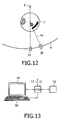
- Fig. 12 shows a simplified schematic representation for further explaining the method described with reference to Fig. 11.
- a radiation emitted by the source of radiation 4 is transmitted through the object of interest 7 and may be measured by means of the primary radiation detector comprising line 15.
- the scatter radiation scattered from the object of interest 7 may be determined by means of the scatter radiation detector 30.
- Fig. 13 shows an exemplary embodiment of a data processing device for performing the methods of the present invention, for example, the methods described with reference to Figs. 10 and 11.
- a central processing unit (CPU) or image processor 1 is connected to a memory 2 for storing read outs from the detectors or the finally reconstructed data.
- the data may be acquired by a CSCT scanner as depicted in Figs. 1 and 6.
- the data processor 1 may furthermore be connected to a plurality of input/output-network or other diagnosis devices.
- the image processor 1 is furthermore connected to a display 4 (for example to a computer monitor) for displaying information or images computed or adapted in the image processor 1. An operator may interact with the data processor 1 via a keyboard 5 and/or other input or output devices which are not depicted in Fig. 1.
- the present invention described above may, for example, be applied in the field of medical imaging. However, as described above, the present invention may also be applied in the field of non-destructive testing or baggage inspection.
- the present invention may allow for a very good spectra resolution of reconstructed scatter functions, for example in order to discriminate materials having the same attenuation values. Furthermore, an improved image quality in particular for medical applications may be achieved.
- the present invention may be applied as add-on functionality for cone-beam CT systems.
- the present invention is applied in conjunction with non-energy resolving detectors.
Landscapes
- Health & Medical Sciences (AREA)
- Engineering & Computer Science (AREA)
- Life Sciences & Earth Sciences (AREA)
- Medical Informatics (AREA)
- Physics & Mathematics (AREA)
- Molecular Biology (AREA)
- Biomedical Technology (AREA)
- General Health & Medical Sciences (AREA)
- Nuclear Medicine, Radiotherapy & Molecular Imaging (AREA)
- Optics & Photonics (AREA)
- High Energy & Nuclear Physics (AREA)
- Surgery (AREA)
- General Physics & Mathematics (AREA)
- Theoretical Computer Science (AREA)
- Biophysics (AREA)
- Pathology (AREA)
- Radiology & Medical Imaging (AREA)
- Heart & Thoracic Surgery (AREA)
- Veterinary Medicine (AREA)
- Animal Behavior & Ethology (AREA)
- Public Health (AREA)
- Spectroscopy & Molecular Physics (AREA)
- Toxicology (AREA)
- Pulmonology (AREA)
- Analysing Materials By The Use Of Radiation (AREA)
- Apparatus For Radiation Diagnosis (AREA)
- Length-Measuring Devices Using Wave Or Particle Radiation (AREA)
Abstract
Description
- The present invention relates to the field of coherent-scatter computed tomography (CSCT), where a fan-beam is applied to an object of interest. In particular, the present invention relates to a method of reconstructing coherent-scatter computed tomography data of an object of interest, to a coherent-scatter computed tomography apparatus, to a data processing device for reconstructing coherent-scatter computed tomography data and to a computer program for reconstructing coherent-scatter computed tomography data.
-
US 4,751,722 describes a device based on the principle of registration of an angled distribution of coherent scattered radiation within angles of 1° to 12° as related to the direction of the beam. As set forth in theUS 4,751,722 , the main fraction of elastic scattered radiation is concentrated within angles of less than 12° for photon energies >40 keV, and the scattered radiation has a characteristic angle dependency with well marked maxima, the positions of which are determined by the irradiated substance itself. As the distribution of the intensity of the coherently scattered radiation in small angles depends on the molecular structure of the substance, different substances having equal absorption capacity (which cannot be differentiated with conventional transillumination or CT) can be distinguished according to the distribution of the intensity of the angled scattering of coherent radiation typical for each substance. - Due to the improved capabilities of such systems to distinguish different object materials, such systems find more and more application in medical or industrial fields.
- The dominant component of low-angle scatter is coherent scatter. Because coherent scatter exhibits interference effects which depend on the atomic arrangement of the scattering sample, coherent scatter computer tomography (CSCT) is in principle a sensitive technique for imaging spatial variations in the molecular structure of tissues or other materials across a 2D object section.
- Harding et al. "Energy-dispersive x-ray diffraction tomography" Phys. Med. Biol., 1990, Vol. 35, No. 1, 33-41 describes an energy dispersive x-ray diffraction tomograph (EXDT) which is a tomographic imaging technique based on an energy analysis at fixed angle, of coherent x-ray scatter excited in an object by polychromatic radiation. According to this method, a radiation beam is created by the use of suitable aperture systems, which has the form of a pencil and thus is also referred to as a pencil beam. Opposite to the pencil beam source, one detector element suitable for an energy analysis is arranged for detecting the pencil beam altered by the object of interest.
- Due to the use of the pencil beam in combination with only one detector element, only a limited number of photons emitted by the source of radiation and thus only a reduced amount of information can be measured. In case EXDT is applied to larger objects such as for example to pieces of baggage, EXDT has to be used in a scanning mode thus causing extremely long measurement times.
- A coherent scatter set-up applying a fan-beam primary beam and a 2D detector in combination with CT was described in
US 6,470,067 B1 thus overcoming the long measurement time involved in EXDT scanning mode. The shortcoming of the angle-dispersive set-up in combination with a polychromatic source are blurred scatter functions, which is described in e.g. Schneider et al. "Coherent Scatter Computer Tomography Applying a Fan-Beam Geometry" Proc. SPIE, 2001, Vol. 4320 754-763. - Regarding attenuation compensation and beam hardening compensation this articles states: "... the projection data is normalized using the primary beam data for each detector row. This approximates the attenuation of the scattered beam through the irradiated object to be the same as for the primary beam" and "Future implementations of the reconstruction procedure will use a mean energy value depending on the traversed object thickness and a more realistic spectral intensity distribution function".
- William D. McDavid et al. describe in "Correction for spectral artifacts in cross-sectional reconstruction form x rays" (Medical Physics, Vol.4, No.1, 1977, p.54) a method for compensating beam hardening: "One first calculates or measures with reference to the incident spectrum, the value of In(I0/I) as a function of increasing mass thickness t of water. This information it then used in reverse (assuming the materials encountered within the scan are sufficiently water-like in their attenuation properties) to determine the effective water mass thickness t to which a particular measured I corresponds. From this t, the attenuation of monoenergetic beam of a convenient effective energy can be derived."
- O. Nalcioglu and R. Y. Lou describe in "Post-reconstruction Method for Beam Hardening in Computerised Tomography" (Phys. Med. Biol., 1979, Vol.24, No.2, p.330) another method for correcting the beam hardening artefacts in computerised tomography: "After an initial reconstruction of the object the uncorrected image is used to estimate the amount of bone and tissue along each ray. The bone and tissue lengths obtained from the initial reconstruction are used to add a correction term to each original projection. A second reconstruction using the corrected projection data yields the final beam hardening corrected image".
- In today's CT scanners, usually polychromatic x-ray sources are used as radiation sources. No exact reconstruction of a scattering function for a voxel is known for polychromatic primary radiation as emitted from such polychromatic x-ray sources.
- It is an object of the present invention to provide for an improved reconstruction of coherent-scatter computed tomography data.
- This object is achieved by the method of reconstructing coherent scatter computed tomography data as defined in
claim 1. - It has been found that a scattering angle for a given momentum transfer depends on the energy of the scattered photon and the signal structure measured on the respective scatter radiation detector is then a function of superimposed scatter projections for the different energies weighted with the intensity and the energy-dependent attenuation- When images are reconstructed from polychromatic projection, i.e. projections taken with a polychromatic source of radiation, an average energy of the spectrum may be used and then, a monochromatic reconstruction may be applied by using this average energy. However, this may cause a smearing of the scatter function due to the spectrum distribution of the primary radiation.
- According to the present invention as set forth above, the scatter radiation data is compensated for beam-hardening effects. This may reduce a smearing of the reconstructed scatter function. Furthermore, this may enable a quasi-exact determination of the back-projection paths by taking into account the beam-hardening effect.
- According to the present invention, a CT reconstruction is performed prior to the CSCT reconstruction. This advantageously allows for a quasi-exact calculation of the back-projection path (of materials occurring on these paths) by taking into account, the beam-hardening effect on the average energy of the scattered photons.
- According to a preferred embodiment of the present invention as set forth in
claim 4, on the basis of the attenuation data, materials are determined located on a path of a scattered photon of the scatter radiation. This is done on the basis of the CT reconstruction. Then, for performing a correction or compensation of the scatter radiation data, these materials are taken into account and beam-hardening effects and in particular absorption effects may be compensated for in the scatter radiation data. A CSCT reconstruction is then performed on the basis of the corrected scatter radiation data. - According to another exemplary embodiment of the present invention as set forth in
claim 5, a coherent-scatter computed tomography apparatus is provided where a beam-hardening compensation of scatter radiation data is performed. Advantageously, this coherent-scatter computed tomography apparatus may be part of a cone-beam CT system. Due to the described reconstruction according to the present invention which may allow for an improved image quality, this apparatus may advantageously be used in medical imaging for material analysis and, for example, for baggage inspection. Advantageously, for these applications a good resolution of the scatter function which may be achieved with the apparatus according to the present invention is important. - Exemplary embodiments of the coherent-scatter computed tomography apparatus according to the present invention are set forth in
claims - According to another exemplary embodiment of the present invention as set forth in
claim 8, a data processing device is provided comprising a memory and a data processor. The data processing device according to this exemplary embodiment is adapted to perform the method of the present invention. - According to another exemplary embodiment of the present invention as set forth in
claim 9, a software program for reconstructing coherent-scatter computed tomography data of an object of interest is provided wherein, when the computer software is executed on one of the data processor and a coherent-scatter computed tomography apparatus, an operation in accordance with the method of the present invention is performed. The computer program according to the present invention may be stored on a computer readable medium, such as a CD-ROM. The computer program may also be presented over a network such as the WorldWideWeb and may be downloaded into the working memory of a data processor from such a network. The computer program may be written in any suitable programming language, such as C++. - It may be seen as a gist of an exemplary embodiment of the present invention that a beam-hardening compensation is performed on the scatter radiation data before the scatter radiation data is used for reconstruction. This may allow for a very good spectral resolution of reconstructed scatter functions and may allow to obtain an improved image quality.
- These and other aspects of the present invention are apparent from and will be elucidated with reference to the embodiments described hereinafter and with reference to the following drawings:
- Fig. 1 shows a schematic representation of an exemplary embodiment of a computer-tomograph according to the present invention.
- Fig. 2 shows a schematic representation of a geometry of the computer-tomograph of Fig. 1 for the measurement of coherent scatter radiation.
- Fig. 3 shows another schematic representation of the geometry of the computer-tomograph of Fig. 1.
- Fig. 4 shows another schematic representation of a measurement geometry of the computer-tomograph of Fig. 1 for further explaining the present invention.
- Fig. 5 shows another schematic representation of a side view of the geometry of the computer-tomograph of Fig. 1.
- Fig. 6 shows another schematic representation for further explaining a scatter event occurring in the computer-tomograph of Fig. 1.
- Fig. 7 shows a schematic representation of a multi-line CSCT scanner according to another exemplary embodiment of the present invention.
- Fig. 8 shows back-projection paths used for performing a back-projection according to an exemplary embodiment of the present invention.
- Fig. 9 shows a table used for determining an energy shift according to an exemplary embodiment of the present invention.
- Fig. 10 shows a flow-chart of a method of operating the computer-tomograph which does not constitute an embodiment of the present invention.
- Fig. 11 shows the flow-chart of the embodiment of the method of operating the computer-tomograph according to the present invention.
- Fig. 12 is a simplified schematic representation of a scatter event for further explaining the method depicted in Fig. 11.
- Fig. 13 shows a simplified schematic representation of an exemplary embodiment of a data processing device according to the present invention adapted to perform the methods of the present invention.
- In the following description of Figs. 1 - 13, the same reference numerals will be used for the same or corresponding elements.
- Fig. 1 shows an exemplary embodiment of a computer-tomograph according to the present invention. With reference to this exemplary embodiment, the present invention will be described for the application in baggage inspection, for example to detect hazardous materials, such as explosives, in items of baggage. However, it has to be noted that the present invention is not limited to the fields of baggage inspection, but can also be used in other industrial or medical applications, such as, for example, in bone imaging or discrimination of tissue types in medical applications. Also, the present invention may be used in the field of non-destructive testing.
- The computer-tomograph depicted in Fig. 1 comprises a
gantry 1, which is rotatable around arotational axis 2. Thegantry 1 is driven by means of amotor 3.Reference character 4 designates the source of radiation, such as an x-ray source which, according to an aspect of the present invention, emits polychromatic radiation. -
Reference numeral 9 designates a collimator, e.g. a slit diaphragm. The fan plane or scan plane offan beam 11 penetrating through the object ofinterest 7 intersects atransmission detector line 15 of theradiation detector 8. - In other words, the
fan beam 11 is directed such that it penetrates the item ofbaggage 7 arranged in the center of thegantry 1, i.e. in an examination region of the computer-tomograph, and impinges onto thedetector 8. As described above, thedetector 8 is arranged on thegantry 1 opposite to theradiation source 4 such that the fan plane of thefan beam 11 intersects the row orline 15 of thedetector 8. Thedetector 8 is depicted in Fig. 1 as having seven detector lines, each comprising a plurality of detector elements. As mentioned above, thedetector 8 is arranged such that theprimary radiation detector 15, i.e. the middle line of thedetector 8, is in the fan plane of thefan beam 11. - The remaining six lines of the
detector 8, i.e. the threedetector lines detector line 15 indicated with hatching, are scatter radiation detector lines.Such detector lines fan beam 11. In other words, thoselines gantry 1 opposite to thex-ray source 4 with an offset from the fan plane in a direction parallel to therotational axis 2 or in a direction normal to the fan plane. Thedetector line 30 is arranged with a positive offset with respect to the direction of therotational axis 2 depicted in Fig. 1 whereas theline 34 is arranged with a negative offset from the fan plane with respect to the direction of therotational axis 2 depicted in Fig. 1. - The detector lines 30 and 34 are arranged at the
gantry 1 such that they are parallel to the fan plane and out of the fan plane with such an offset in a positive or negative direction of therotational axis 2 of thegantry 1 such that they receive or measure a scatter radiation scattered from the item ofbaggage 7 in the examination area of the computer-tomograph. Thus, in the following,lines - The detector elements of the
detector lines line 15 orline lines line 15 may be a line of a scintillator detector cell. The primary beam detectors and the scatter radiation detectors may be placed in separate housings. - It has to be noted that the provision of only one
line lines 30 and/or 34 is provided. Also, the provision of only oneline 15 measuring the attenuation caused by the item ofbaggage 7 of the primary beam of thefan beam 11 in the fan plane may be sufficient. However, as in the case of thelines detector lines 15 may further increase the measurement speed of the computer-tomograph. In the following, the term "primary radiation detector" will be used to refer to a detector, including at least one detector line for measuring an attenuation of the primary radiation of thefan beam 11. - As may be taken from Fig. 1, the detector cells of the
detector 8 are arranged in lines and columns, wherein the columns are parallel to therotational axis 2, wherein the lines are arranged in planes perpendicular to therotational axis 2 and parallel to the slice plane of thefan beam 11. - During a scan of the item of
baggage 7, theradiation source 4, the collimator 9 (or an aperture system) and thedetector 8 are rotated along thegantry 1 in the direction indicated byarrow 16. For rotation of thegantry 1 themotor 3 is connected to amotor control unit 17, which is connected to acalculation unit 18. - In Fig. 1, the item of
baggage 7 is disposed on aconveyor belt 19. During the scan of the item ofbaggage 7, while thegantry 1 rotates around the item ofbaggage 7, theconveyor belt 19 displaces the item ofbaggage 7 along a direction parallel to therotational axis 2 of thegantry 1. By this, the item ofbaggage 7 is scanned along a helical scan path. Theconveyor belt 19 can also be stopped during the scans to thereby measure single slices. - The
detector 8 is connected to acalculation unit 18. Thecalculation unit 18 receives the detection results, i.e. the readouts from the detector elements of thedetector 8, and determines a scanning result on the basis of the scanning results from thedetector 8, i.e. from the scatter-detector lines line 15 for measuring the attenuation of the primary radiation of the fan-beam 11. In addition to that, thecalculation unit 18 communicates with themotor control unit 17 in order to coordinate the movement of thegantry 1 with themotors conveyor belt 19. - The
calculation unit 18 is adapted for reconstructing an image from readouts of the primary radiation detector, i.e.detector line 15 and the scatter radiation detector, i.e. lines 30 and 34. The image generated by thecalculation unit 18 may be output to a display (not shown in Fig. 1) via aninterface 22. - Furthermore, the
calculation unit 18 is adapted for the detection of explosives in the item ofbaggage 7 on the basis of the readouts of thelines calculation unit 18 determines that the measurement values read out from thedetector 8 match with characteristic measurement values of an explosive, thecalculation unit 18 automatically outputs an alarm via aloudspeaker 21. - Fig. 2 shows a simplified schematic representation of a geometry of the CSCT scanning system depicted in Fig. 1. As may be taken from Fig. 2, the
x-ray source 4 emits the fan-beam 11 such that it includes the item ofbaggage 7 in this case having a diameter of u and covers theentire detector 8. The diameter of the object region may, for example, be 100 cm. In this case, an angle α of the fan-beam 11 may be 80 °. In such an arrangement, a distance v from thex-ray source 4 to the center of the object region is approximately 80 cm and the distance of thedetector 8, i.e. of the individual detector cells from thex-ray source 4, is approximately w = 150 cm. - As can be taken from Fig. 2, according to an aspect of the present invention, the detector cells or lines can be provided with
collimators 40 to avoid that the cells or lines measure unwanted radiation having a different scatter angle. Thecollimators 40 have the form of blades or lamellas, which can be focused towards the source. The spacing of the lamellas can be chosen independently from the spacing of the detector elements. - Instead of a
bent detector 8 as depicted in Figs. 1 and 2, it is also possible to use a flat detector array. - Fig. 3 shows another schematic representation of a detector geometry as used in the computer tomograph of Fig. 1. As already described with reference to Fig. 1, the
detector 8 may comprise one, two ormore detector lines lines 15 for measuring the attenuation of the primary fan-beam caused by the item ofbaggage 7. As may be taken from Fig. 3, preferably thedetector 8 is arranged such that themiddle line 15 of thedetector 8, is within the fan plane of the fan-beam 11 and thereby measures the attenuation in the primary radiation. As indicated byarrow 42, the radiation source ofx-ray source 4 and thedetector 8 are rotated together around the item of baggage to acquire projections from different angles. - As depicted in Fig. 3, the
detector 8 comprises a plurality of columns t. - Fig. 4 shows another schematic representation of the geometry of the computer tomograph depicted in Fig. 1 for further explaining the present invention. In Fig. 4, a
detector 46 is depicted, comprising only oneline 15 and only oneline 30. Theline 15 is arranged in the fan plane of the fan-beam 11 formed by thecollimator 9. Theline 15 comprises, for example, scintillator cells or other suitable cells for measuring the attenuation of the primary beam of the fan-beam 11 and allows for an integral measurement of the attenuation of the primary fan-beam caused by the object of interest in the object region or examination region. -
Line 30 depicted in Fig. 4 may include energy resolving cells or scintillator cells. As may be taken from Fig. 4, theline 30 is arranged parallel to the fan plane of the fan-beam 11 but out of the plane. In other words, theline 30 is arranged in a plane parallel to the fan plane and parallel to theline 15. The fan plane may also be referred to as slice plane. -
Reference numeral 44 indicates a scatter radiation, i.e. a photon scattered by the object of interest, such as the item of baggage. As may be taken from Fig. 4, the scatter radiation leaves the slice plane and impinges onto a detector cell of theline 30. - Fig. 5 shows a side view of the detector geometry of the computer tomograph of Fig. 1. Fig. 5 can also be contemplated as showing a side view of Fig. 4, where, however, instead only the provision of one
line 30 and oneline 15, in Fig. 5 there is provided a plurality of detector lines 32 between theline 30 and theline 15. The detector element Di is arranged with a fixed distance a from the slice plane of the primary fan-beam. According to an aspect of the present invention, for each detector element Di of the column t and for each projection Φ (see Fig. 3) a spectrum I (E, t, Φ) is measured. Performing this measurement for a plurality of projections Φ along a circular or helical scan path, a three-dimensional data set is acquired. Each object pixel is described by three coordinates (x, y, q). Thus, according to an aspect of the present invention, for reconstructing an image or for reconstructing further information from the three-dimensional data set, a 3D → 3D reconstruction method is applied such as the one described inDE 10252662.1 , which is hereby incorporated by reference. - Fig. 6 shows a schematic representation for explaining a scatter event occurring in the object of interest. The intensity I at the
detector 8 may be determined from the following equation:
- From
equation 3 it may be taken that the detector signal I at adetector 8 is a superposition of scattered projections for a variety of energies which are weighted with the intensity I0(E) and the attenuation which is dependent on the energy. F is the scatter function. The attenuation factors α(E) and β(E) describe the attenuation of the incoming radiation along the path from the source to the location of the scatter event and from the location of the scatter event to the detector. - A simple approach for reconstructing images from the projection data which has been determined on the basis of polychromatic radiation is to calculate a mean energy of the spectrum and then to perform a "monochromatic" reconstruction. However, as indicated above, this may cause a smearing of the scattered function in dependence of the wave vector transfer in the reconstructed images caused by the spectral nature of the primary radiation.
- According to Figs. 10 and 11 methods are provided wherein the polychromatic nature, and by this the beam-hardening of the primary radiation, is contemplated for the determination of the back-projection paths. This may allow for a quasi-polychromatic reconstruction.
- Fig. 7 shows a schematic drawing of an exemplary embodiment of a multi-line CSCT scanner. This scanner is provided with a
detector 48, comprising a plurality of lines of energy resolving detector elements, which may be the same as the ones described with reference to Fig. 1. The source ofradiation 9 is provided with collimators, such that it generates a fan-beam of x-rays. The arrangement of thedetector 48 and the source ofradiation 49 is such that thedetector 48 is focus centered. The view depicted in Fig. 6 is parallel to the scanned plane or slice plane in order to further clarify the scanning process out of the x-y plane, i.e. the rotation plane of the source ofradiation 49 and thedetector 48. As may be taken from Fig. 6, a distance between the source ofradiation 49 and thedetector 48 is indicated as "SD", a distance between thesource 49 and the center ofrotation 47 is indicated by S, a distance between the scatter center and thedetector 48 is indicated by d, a distance between a detector element receiving radiation, the scanned plane or sliced plane is indicated by a and h indicates a height of thedetector 48. - The z coordinate axis is a normal on the center of the rotation plane of the source of
radiation 49, i.e. the axis of rotation of the source ofradiation 49. The y coordinate is in the rotation plane of the source of radiation. - As may be taken from Fig. 7, for the following description, a CSCT scanner with a
polychromatic x-ray source 49 and adetector 49 is considered. The detector comprises or consists of energy resolving detector elements, which may be similar to the ones described with reference to Fig. 1. The emitted x-rays have been collimated, such that a fan-beam radiates the object of interest located in an area around the center ofradiation 47. - The following method of operation may be applied in the above scanner, or in the scanner described with reference to Fig. 1, for reconstructing the CSCT data, i.e. for reconstructing an image from the read-outs of the
detectors - Step 1: The data is measured during a circular acquisition referring to the source trajectory in the x-y-z space. In other words, read-outs are gathered from
detectors radiations detectors - Step 2: The acquired CSCT data is resorted and extrapolated, such that it corresponds to an acquisition along a helical trajectory in the x-y-q space.
- Step 3: A further step may be performed in order to pre-process the data according to conventional helical reconstruction algorithms, such as, for example, the exact reconstruction technique described by Katsevich "Analysis of an exact inversion algorithm for spiral cone-beam CT", Phys. Med. Biol., vol. 47, p. 2583-2597, 2002, which is hereby incorporated by reference.
- Step 4: Then, the resorted and/or extrapolated data may be back projected. This back-projection may be performed along the curved lines in the x-y-q space. These curved lines may, for example, be hyperbolas.
- This operation, in
particular step 2, will be described in more detail in the following: - CSCT makes use of coherently scattered x-rays, in order to reconstruct the coherent scatter form factor F 2(q). The differential cross-section for coherently scattered x-rays dσ Rayleigh / dΩ is given by

- According to Fig. 6, the scatter angle is given by the distance d of the scatter center from the detector and the distance a of the detector element which receives the scattered radiation from the scanning plane:

- Together with Eq. (6), this yields:

- The x-y-q space, Eq. (8) describes hyperbolas. These hyperbolas can be approximated by straight lines. Among several possibilities is, for example, an approximation such that the area under a straight line matches the area of the corresponding hyperbola. Another approximation is described here. The straight line intersects the hyperbola at the beginning (d max) and at the end (d min) of the region of interest:

- Fig. 8 shows such hyperbolas. In detail, Fig. 8 shows a back-projection path as determined by
creation 8. As may be taken from Fig. 8, for each mean energy, a new path is obtained. - A scanning system is considered, such as the ones depicted in Figs. 1 and 6, where the real path can be resorted and extrapolated such that it corresponds to an acquisition along a helical trajectory in the x-y-q space. The extrapolation of the data measured on a circular trajectory to virtual neighboring trajectories is done by using John's Equation. The idea of John's Equation is that the space of line integrals through 3D space is 4D, thus the mapping from object function to its line integral function creates an additional dimension, as described in S. K. Patch, "Consistency conditions upon 3D CT data and the wave equation", Phys. Med. Biol. 47, 2637-2650.
US Patent 6173030 (1999 ), which is hereby incorporated by reference. - Line integrals for the virtual source position q̃ may be extrapolated from the line integrals measured for source positions for q̃ = 0.
- This implies redundancy in line integral space, which is then used to construct unmeasured from measured data as described in S. K. Patch "Computation of unmeasured third-generation VCT views from measured views", IEEE Trans. Med. Img. MI-21, 801-813.
US Patent 6292526 (1999 ), which is hereby incorporated by reference. John's Equation is parametrized as follows for the set of geometry parameters, as described in M. Defrise, F. Noo, H. Kudo, "Improved 2D rebinning of helical cone-beam CT data using John's equation", Proc. 2002 IEEE Nuclear Science and Medical Imaging Symposium, Norfolk (VA), Paper M10-74, which is hereby incorporated by reference:
where R is the distance from the virtual source position to the iso-center and u is the distance from the central ray to the exposed detector column in fan direction. The line integrals are denoted by g and the derivative of the line integral with respect to a variable is expressed by the index. From the measured line integrals g, the line integrals gq̃ can be extrapolated for a virtual source position g̃ according to
- Therefore, Eq. (10) has to be solved for q̃. Reforming of Eq. (10) to

and partial integration with respect to u leads to
which are the line integrals for the virtual source position q̃. - The acquired and extrapolated data can now be resorted such that it corresponds to an acquisition along a helical trajectory in the x-y-q space. Let R̃ be the vector from the center of rotation of the scanning system to the virtual source. The helical trajectory results in:

where α denotes the angular source position in relation to the x-axis. - In a certain range, each value of q ∈ [q min, q max] can be expressed by the linear equation

which fulfills the data acquisition of a helical trajectory in the x-y-q space. By this description, it is possible to define an offset α 0 as a starting point for the helical data acquisition, in order to use redundant data for the reconstruction process. This may lead to better image quality. - The above described
steps 1 to 4, inparticular Step 3 may be applied and implemented in the CSCT scanner depicted and described with reference to Figs. 1 to 5, in the scanner depicted in Fig. 6 and in the data processing device depicted in Fig. 13. - As already mentioned above, during the transmission through a material, the x-ray spectrum becomes harder. Due to this, the mean energies of the transmitted x-ray spectra are different depending on the primary spectrum and the material encountered in the object of interest. This causes that when performing a back-projection along the path as set forth in
equation 5 on the basis of the different mean energies, different back-projection paths are obtained. It has been found that for contemplating this effect during the reconstruction, the mean energies of the respective back-projection paths have to be obtained. This may be done as set forth in the methods described with reference to Figs. 10 and 11. - As shown above, the path of the scatter radiation and due to this, the factor β(E) depends on the scatter angle. In the following it is assumed that the attenuation of the scattered radiation is the same as the attenuation of the directly transmitted radiation. The attenuation of the transmitted radiation, i.e. of the primary radiation, may be determined as

primary radiation detector 15. The application of this assumption causes that the product α(E) x β(E) is independent of the path. - For determining a shift of the mean energies of the scattered photons on the basis of the mean attenuation

- In the following, on the basis of the mean attenuation a simulation is performed with respect to the mean energy shift. In other words, it is determined how much the mean energy is shifted up.
- For example, for water, an equivalent water thickness may be determined on the basis of a mean attenuation


- Fig. 9 shows a table comprising approximated linear dependencies between energy and a thickness of water and PMMA for a plurality of filtered tungsten spectra. For example, the table of Fig. 9 shows in the first line that when using an x-ray tube with 150 keV and 1.5 mm of Aluminium filter, the mean energy emitted by the tube is 63.3 keV. Assuming an equivalent water thickness of 10 cm, the energy shift would be 7.2 keV. Thus, the mean energy which may be determined at the
detector 8 which has been corrected for beam-hardening effects and which has been attenuation corrected is 63.3 keV + 7.2 keV = 70.5 keV. - Fig. 10 shows a flow-chart of a method which does not lie within the scope of the claims.
- After the start in step S1, an air scan is performed in step S2. An air scan is a scan where no object of interest is in the examination region of the CT scanner. The air scan serves to determine I0. Then, in the subsequent step S3, a mean attenuation

primary radiation detector 15. In other words, a determination of mean attenuation values is performed on the basis of the primary radiation. - Then, in the subsequent step S5 a determination of an equivalent water thickness is performed on the basis of the mean attenuation. This equivalent water thickness (or Lucite thickness (or a thickness of a mean material) may be determined on the basis of the following equation:

- Then, in the subsequent step S6, an energy shift caused by the material is calculated from the equivalent water thickness. This may be done, for example, by referring to a predetermined table such as the table depicted in Fig. 9.
- Then, in the subsequent step S7, the initial average energy of the scatter radiation is corrected or compensated by using the energy shift. In other words, in step S7 a compensation for beam-hardening effects and in particular an attenuation compensation is performed. Then, in subsequent step S8, a reconstruction is performed by using the corrected energy measurements. The reconstruction may be performed along the back-projection path described above. In other words, the reconstruction may be performed in accordance with steps 1 - 4 as described above. Then, the method continues to step S9 where it ends.
- Fig. 11 shows the flow-chart of the exemplary embodiment of a method of operating the CT scanner system or data processing apparatus according to the present invention. In contrast to the method described with reference to Fig. 10 where no preliminary CT reconstruction is performed, in the method described with reference to Fig. 11, a CT reconstruction may be performed before the actual reconstruction. Advantageously, this may allow for an improved compensation of beam-hardening effects and in particular an improved absorption compensation.
- After the start in step S10, an air scan is performed in step S11 for determining I0. Then, in the subsequent step S12, a CT acquisition is performed. In other words, in step S 12, a data acquisition of the object volume of interest may be performed, for example, along a helical trajectory. For this, a fan-beam may be used. Advantageously, by using such an arrangement, the projection data of the transmitting as well as of the scattered radiation may be determined at the same time. However, in a variant of this exemplary embodiment of the present invention, a pre-scanning may be performed where only the transmitting radiation is measured, i.e. only the read outs of the primary radiation detector are gathered. Then, a second scan may be performed for determining the scatter radiation.
- Then, in the subsequent step S 13, from the readouts of the primary radiation detector, i.e. from the transmitted radiation data, a volume data set is reconstructed wherein each voxel comprises an absorption coefficient of the object of interest contained in the object volume of interest. Then, in the subsequent step S14, the compensation of beam-hardening effects and in particular the absorption compensation is performed. Here, the mean energy for the scattered photons is determined on the basis of the volume data set by taking into account materials of the object of interest occurring on the path of the scattered photons through the object of interest. These materials may be discriminated from the volume data set determined in step S13. For example, these materials may be discriminated by performing suitable thresholding operations.
- In other words, since the projection path of the object is known for a scattered photon, for a known spectrum, the attenuation along this path is calculated, By performing suitable thresholding operations, materials along the scatter path of the respective photon may be identified and the absorption spectra thereof may be taken into account. From the resulting spectra, a mean energy may be determined for the scattered photon.
- Then, in the subsequent step S15, a reconstruction may be performed by using these mean energies. Due to this, during the actual reconstruction performed in step S15, where the scatter function is determined for each voxel, the mean energy determined in step S14 is used in
equation 5 and thus may allow for improved spectral resolution of the reconstructed scatter function in dependence of the wave vector transfer. Furthermore, on the basis of the absorption values determined in step S13, an absorption correction may be performed for the respective projection path which also may allow for an improved image quality. Then, the method continues to step S16 where it ends. - Fig. 12 shows a simplified schematic representation for further explaining the method described with reference to Fig. 11. As may be taken from Fig. 12, a radiation emitted by the source of
radiation 4 is transmitted through the object ofinterest 7 and may be measured by means of the primary radiationdetector comprising line 15. The scatter radiation scattered from the object ofinterest 7 may be determined by means of thescatter radiation detector 30. - In a preliminary step, a CT reconstruction on the basis of the read outs of the
detector line 15, i.e. of the primary radiation detector, is performed. From this, a volume data set is reconstructed. From the volume data set, materials which are encountered by thescatter radiation 44 on its path through the object ofinterest 7 may be determined. The beam-hardening effect caused by these materials is taken into account and also the absorption spectra caused by these materials may be taken into account to correct the energy actually measured bydetector line 30, - Fig. 13 shows an exemplary embodiment of a data processing device for performing the methods of the present invention, for example, the methods described with reference to Figs. 10 and 11. As may be taken from Fig. 9, a central processing unit (CPU) or
image processor 1 is connected to amemory 2 for storing read outs from the detectors or the finally reconstructed data. As indicated before, the data may be acquired by a CSCT scanner as depicted in Figs. 1 and 6. Thedata processor 1 may furthermore be connected to a plurality of input/output-network or other diagnosis devices. Theimage processor 1 is furthermore connected to a display 4 (for example to a computer monitor) for displaying information or images computed or adapted in theimage processor 1. An operator may interact with thedata processor 1 via akeyboard 5 and/or other input or output devices which are not depicted in Fig. 1. - The present invention described above may, for example, be applied in the field of medical imaging. However, as described above, the present invention may also be applied in the field of non-destructive testing or baggage inspection. Advantageously, the present invention may allow for a very good spectra resolution of reconstructed scatter functions, for example in order to discriminate materials having the same attenuation values. Furthermore, an improved image quality in particular for medical applications may be achieved. The present invention may be applied as add-on functionality for cone-beam CT systems. Preferably, the present invention is applied in conjunction with non-energy resolving detectors.
with the energy E of the corresponding x-ray photon, Planck's constant h and the speed of light c. For scattering under small angles, e.g. the angle regime of interest here is between 0 and 6°, sin(Θ/2) can be approximated by Θ / 2, and Eq.(5) can be written as

Claims (6)
- Method of reconstructing coherent scatter computed tomography (CSCT) data of an object of interest, the method comprising the steps of:- acquiring attenuation data of the object of interest from primary radiation transmitted through the object of interest;- reconstructing a volume data set comprising absorption coefficients of the object of interest;- determining radiation spectra for scattered photons of the scatter radiation on the basis of the volume data set;- determining mean energies of the scattered photons on the basis of the radiation spectra;- performing a beam hardening compensation of scatter radiation data on the basis of the acquired attenuation data; wherein the scatter radiation data is based on scatter radiation scattered from the object of interest; and- reconstructing the coherent scatter computed tomography data by using the compensated scatter radiation data and the determined mean energies,
- The method of claim 1, wherein, on the basis of the CT reconstruction, materials are determined which are located on a path of a scattered photon of the scatter radiation in the object of interest; wherein absorption spectra of said material are used for determining the mean energy of the scattered photon.
- Coherent scatter computed tomography apparatus, the apparatus comprising:a detector assembly (1, 4, 15, 30, 34) with a source of radiation (4), a first detector (15) and a second detector (30, 34); wherein the detector assembly is arranged for rotation around an object of interest (7); wherein the first and second detectors are arranged opposite to the source of radiation; wherein the first detector is arranged for acquiring attenuation data of the object of interest from primary radiation transmitted through the object of interest; wherein the second detector is arranged for acquiring scatter radiation data of the object of interest from scatter radiation scattered from the object of interest; wherein the apparatus is adapted for performing following steps:- acquiring attenuation data of the object of interest from primary radiation transmitted through the object of interest;- reconstructing a volume data set comprising absorption coefficients of the object of interest;- determining radiation spectra for scattered photons of the scatter radiation;- determining mean energies of the scattered photons on the basis of the radiation spectra;- performing a beam hardening compensation of scatter radiation data on the basis of the acquired attenuation data; wherein the scatter radiation data is based on scatter radiation scattered from the object of interest; and- reconstructing the coherent scatter computed tomography data by using the compensated scatter radiation data and the determined mean energies.
- The apparatus of claim 3, wherein, on the basis of the CT reconstruction, materials are determined which are located on a path of a scattered photon of the scatter radiation in the object of interest; wherein absorption spectra of said materials are used for determining the mean energy of the scattered photon.
- Data processing device for reconstructing coherent scatter computed tomography data of an object of interest (7), wherein the device comprises a memory (52) for storing attenuation data and scatter radiation data; and a data processor (51) adapted to perform the following operation:- acquiring attenuation data of the object of interest from primary radiation transmitted through the object of interest;- reconstructing a volume data set comprising absorption coefficients of the object of interest;- determining radiation spectra for scattered photons of the scatter radiation;- determining mean energies of the scattered photons on the basis of the radiation spectra;- performing a beam hardening compensation of scatter radiation data on the basis of the acquired attenuation data; wherein the scatter radiation data is based on scatter radiation scattered from the object of interest; and- reconstructing the coherent scatter computed tomography data by using the compensated scatter radiation data and the determined mean energies.
- Computer program for reconstructing coherent scatter computed tomography data of an object of interest (7), wherein, when the computer program is executed on one of a data processor and a coherent scatter computed tomography apparatus, the following operation is executed:- acquiring attenuation data of the object of interest from primary radiation transmitted through the object of interest;- reconstructing a volume data set comprising absorption coefficients of the object of interest;- determining radiation spectra for scattered photons of the scatter radiation;- determining mean energies of the scattered photons on the basis of the radiation spectra;- performing a beam hardening compensation of scatter radiation data on the basis of the acquired attenuation data; wherein the scatter radiation data is based on scatter radiation scattered from the object of interest; and- reconstructing the coherent scatter computed tomography data by using the compensated scatter radiation data and the determined mean energies.
Priority Applications (1)
| Application Number | Priority Date | Filing Date | Title |
|---|---|---|---|
| EP05709011A EP1728215B1 (en) | 2004-03-17 | 2005-03-15 | Beam-hardening and attenuation correction for coherent-scatter computed tomography (csct) |
Applications Claiming Priority (3)
| Application Number | Priority Date | Filing Date | Title |
|---|---|---|---|
| EP04101099 | 2004-03-17 | ||
| EP05709011A EP1728215B1 (en) | 2004-03-17 | 2005-03-15 | Beam-hardening and attenuation correction for coherent-scatter computed tomography (csct) |
| PCT/IB2005/050904 WO2005091225A1 (en) | 2004-03-17 | 2005-03-15 | Beam-hardening and attenuation correction for coherent-scatter ct |
Publications (2)
| Publication Number | Publication Date |
|---|---|
| EP1728215A1 EP1728215A1 (en) | 2006-12-06 |
| EP1728215B1 true EP1728215B1 (en) | 2008-02-06 |
Family
ID=34961174
Family Applications (1)
| Application Number | Title | Priority Date | Filing Date |
|---|---|---|---|
| EP05709011A Not-in-force EP1728215B1 (en) | 2004-03-17 | 2005-03-15 | Beam-hardening and attenuation correction for coherent-scatter computed tomography (csct) |
Country Status (7)
| Country | Link |
|---|---|
| US (1) | US7453974B2 (en) |
| EP (1) | EP1728215B1 (en) |
| JP (1) | JP2007529738A (en) |
| CN (1) | CN1934590A (en) |
| AT (1) | ATE385595T1 (en) |
| DE (1) | DE602005004653T2 (en) |
| WO (1) | WO2005091225A1 (en) |
Families Citing this family (42)
| Publication number | Priority date | Publication date | Assignee | Title |
|---|---|---|---|---|
| DE602005004653T2 (en) | 2004-03-17 | 2009-01-29 | Philips Intellectual Property & Standards Gmbh | Correction of radiation hardening and attenuation in coherent scatter computed tomography (CSCT) |
| WO2007029129A2 (en) * | 2005-09-06 | 2007-03-15 | Koninklijke Philips Electronics, N.V. | Data handling and analysis in computed tomography with multiple energy windows |
| WO2007039876A2 (en) * | 2005-10-06 | 2007-04-12 | Philips Intellectual Property & Standards Gmbh | Acquisition parameter optimization for csct |
| WO2007046023A2 (en) * | 2005-10-20 | 2007-04-26 | Philips Intellectual Property & Standards Gmbh | Advanced csct detector shapes |
| US7298812B2 (en) * | 2006-03-31 | 2007-11-20 | General Electric Company | Image-based material decomposition |
| CN101501478A (en) * | 2006-08-11 | 2009-08-05 | 皇家飞利浦电子股份有限公司 | System and method for acquiring image data |
| US7486764B2 (en) * | 2007-01-23 | 2009-02-03 | General Electric Company | Method and apparatus to reduce charge sharing in pixellated energy discriminating detectors |
| US8045678B2 (en) * | 2008-03-21 | 2011-10-25 | Mxisystems, Inc. | Dynamically-varied beam energy using a tunable monochromatic X-ray beam |
| US7550737B1 (en) | 2008-05-16 | 2009-06-23 | The Gillette Company | Battery |
| US8712121B2 (en) * | 2008-06-25 | 2014-04-29 | Koninklijke Philips N.V. | Image generation device with optimized dose control |
| EP2146321B1 (en) * | 2008-07-14 | 2012-12-12 | Cefla S.C. | Dynamic error correction in radiographic imaging |
| JP5641748B2 (en) * | 2009-03-18 | 2014-12-17 | 株式会社東芝 | X-ray computed tomography apparatus and data processing method |
| CN102481129B (en) * | 2009-09-02 | 2014-06-18 | 株式会社岛津制作所 | Radiographic apparatus and image acquiring method |
| JP4911373B2 (en) * | 2009-11-26 | 2012-04-04 | 横河電機株式会社 | X-ray measuring device |
| JP5745054B2 (en) * | 2011-07-12 | 2015-07-08 | 株式会社日立メディコ | X-ray CT apparatus, calculation apparatus, and maintenance method for X-ray CT apparatus |
| US8989342B2 (en) * | 2012-04-18 | 2015-03-24 | The Boeing Company | Methods and systems for volumetric reconstruction using radiography |
| CN105073010B (en) * | 2013-04-04 | 2018-04-03 | 东芝医疗系统株式会社 | X-ray computed tomograohy apparatus |
| WO2015012850A1 (en) * | 2013-07-25 | 2015-01-29 | Analogic Corporation | Generation of diffraction signature of item within object |
| WO2015067511A1 (en) * | 2013-11-08 | 2015-05-14 | Koninklijke Philips N.V. | Empirical beam hardening correction for differential phase contrast ct |
| CN103926628A (en) * | 2014-04-22 | 2014-07-16 | 史崇政 | Security inspection device and method for identifying forbidden objects using same |
| FR3023000B1 (en) * | 2014-06-30 | 2016-07-29 | Commissariat Energie Atomique | METHOD AND SYSTEM FOR ANALYZING A DIFFRACTOMETRY OBJECT USING DIFFUSION SPECTRUM AND SPECTRUM IN TRANSMISSION |
| US9405990B2 (en) * | 2014-08-19 | 2016-08-02 | Morpho Detection, Llc | X-ray diffraction imaging system with signal aggregation across voxels containing objects and method of operating the same |
| DE102014218291A1 (en) * | 2014-09-12 | 2016-03-17 | Siemens Aktiengesellschaft | Method for generating a phase contrast dark field display, grid interferometer and X-ray imaging system |
| US9374565B2 (en) | 2014-11-06 | 2016-06-21 | General Electric Company | System and method for multi-material correction of image data |
| CN104605880B (en) * | 2014-12-30 | 2017-06-16 | 沈阳东软医疗系统有限公司 | The generation method and device of a kind of hardening effect data |
| CN107847201B (en) * | 2015-07-14 | 2021-04-30 | 皇家飞利浦有限公司 | Imaging with modulated X-ray radiation |
| US10765383B2 (en) * | 2015-07-14 | 2020-09-08 | Koninklijke Philips N.V. | Imaging with enhanced x-ray radiation |
| JP7015781B2 (en) * | 2015-07-24 | 2022-02-03 | フォト・ダイアグノスティック・システムズ,インコーポレイテッド | Methods and Instruments for Performing Multiple Energy (Including Dual Energy) Computed Tomography (CT) Imaging |
| CN107345925B (en) * | 2016-05-05 | 2019-10-15 | 同方威视技术股份有限公司 | Liquid detecting method and system |
| US10573030B2 (en) | 2017-04-07 | 2020-02-25 | Photo Diagnostic Systems, Inc. | Method for artifact reduction using monoenergetic data in computed tomography |
| JP7534038B2 (en) | 2018-11-30 | 2024-08-14 | アキュレイ インコーポレイテッド | Asymmetric scatter fitting for optimal panel readout in cone-beam computed tomography |
| US11357467B2 (en) | 2018-11-30 | 2022-06-14 | Accuray, Inc. | Multi-pass computed tomography scans for improved workflow and performance |
| US11058369B2 (en) | 2019-11-15 | 2021-07-13 | GE Precision Healthcare LLC | Systems and methods for coherent scatter imaging using a segmented photon-counting detector for computed tomography |
| CN111643104B (en) * | 2020-02-28 | 2022-03-18 | 清华大学 | CT scattering correction method and system |
| US11166690B2 (en) | 2020-03-19 | 2021-11-09 | Accuray, Inc. | Noise and artifact reduction for image scatter correction |
| US20240142392A1 (en) * | 2021-03-04 | 2024-05-02 | Multict Imaging Ltd | X-ray computed tomography (ct) scanner |
| CN113109373B (en) * | 2021-04-14 | 2022-09-27 | 中国兵器科学研究院宁波分院 | Area array industrial CT beam hardening correction method |
| US11647975B2 (en) | 2021-06-04 | 2023-05-16 | Accuray, Inc. | Radiotherapy apparatus and methods for treatment and imaging using hybrid MeV-keV, multi-energy data acquisition for enhanced imaging |
| US11605186B2 (en) | 2021-06-30 | 2023-03-14 | Accuray, Inc. | Anchored kernel scatter estimate |
| US11794039B2 (en) | 2021-07-13 | 2023-10-24 | Accuray, Inc. | Multimodal radiation apparatus and methods |
| US11854123B2 (en) | 2021-07-23 | 2023-12-26 | Accuray, Inc. | Sparse background measurement and correction for improving imaging |
| CN118202234A (en) * | 2021-09-07 | 2024-06-14 | 拉皮斯坎系统股份有限公司 | Method and system for accurate visual layer separation in a display of a scanning system |
Family Cites Families (14)
| Publication number | Priority date | Publication date | Assignee | Title |
|---|---|---|---|---|
| US3965358A (en) * | 1974-12-06 | 1976-06-22 | Albert Macovski | Cross-sectional imaging system using a polychromatic x-ray source |
| US4149081A (en) * | 1976-11-29 | 1979-04-10 | Varian Associates, Inc. | Removal of spectral artifacts and utilization of spectral effects in computerized tomography |
| DE3406905A1 (en) * | 1984-02-25 | 1985-09-05 | Philips Patentverwaltung Gmbh, 2000 Hamburg | ROENTGENGERAET |
| US5335260A (en) * | 1992-11-25 | 1994-08-02 | Arnold Ben A | Calibration phantom and improved method of quantifying calcium and bone density using same |
| EP0660599B2 (en) * | 1993-12-24 | 2002-08-14 | Agfa-Gevaert | Partially-transparent-shield-method for scattered radiation compensation in x-ray imaging |
| JP3901770B2 (en) * | 1996-10-21 | 2007-04-04 | 富士フイルム株式会社 | Energy subtraction processing method and apparatus |
| AU2887499A (en) * | 1998-03-02 | 1999-09-20 | Image Anaylsis, Inc. | Automated x-ray bone densitometer |
| US6157703A (en) * | 1998-10-06 | 2000-12-05 | Cardiac Mariners, Inc. | Beam hardening filter for x-ray source |
| US6421419B1 (en) * | 2000-11-08 | 2002-07-16 | Fuji Photo Film Co., Ltd. | Energy subtraction processing method and apparatus |
| US6507633B1 (en) * | 2001-02-15 | 2003-01-14 | The Regents Of The University Of Michigan | Method for statistically reconstructing a polyenergetic X-ray computed tomography image and image reconstructor apparatus utilizing the method |
| US7248726B2 (en) * | 2001-03-21 | 2007-07-24 | Fujifilm Corporation | Energy subtraction processing method and apparatus |
| DE10252662A1 (en) | 2002-11-11 | 2004-05-27 | Philips Intellectual Property & Standards Gmbh | Medical computer tomography procedure has source rotated around object and back projection image reconstruction using square law distance and cosine beam angle weighting |
| US7065234B2 (en) * | 2004-02-23 | 2006-06-20 | General Electric Company | Scatter and beam hardening correction in computed tomography applications |
| DE602005004653T2 (en) | 2004-03-17 | 2009-01-29 | Philips Intellectual Property & Standards Gmbh | Correction of radiation hardening and attenuation in coherent scatter computed tomography (CSCT) |
-
2005
- 2005-03-15 DE DE602005004653T patent/DE602005004653T2/en not_active Expired - Fee Related
- 2005-03-15 WO PCT/IB2005/050904 patent/WO2005091225A1/en active IP Right Grant
- 2005-03-15 JP JP2007503483A patent/JP2007529738A/en not_active Withdrawn
- 2005-03-15 EP EP05709011A patent/EP1728215B1/en not_active Not-in-force
- 2005-03-15 CN CNA2005800087517A patent/CN1934590A/en active Pending
- 2005-03-15 US US10/598,835 patent/US7453974B2/en not_active Expired - Fee Related
- 2005-03-15 AT AT05709011T patent/ATE385595T1/en not_active IP Right Cessation
Also Published As
| Publication number | Publication date |
|---|---|
| JP2007529738A (en) | 2007-10-25 |
| US7453974B2 (en) | 2008-11-18 |
| ATE385595T1 (en) | 2008-02-15 |
| EP1728215A1 (en) | 2006-12-06 |
| WO2005091225A1 (en) | 2005-09-29 |
| US20070189444A1 (en) | 2007-08-16 |
| DE602005004653T2 (en) | 2009-01-29 |
| DE602005004653D1 (en) | 2008-03-20 |
| CN1934590A (en) | 2007-03-21 |
Similar Documents
| Publication | Publication Date | Title |
|---|---|---|
| EP1728215B1 (en) | Beam-hardening and attenuation correction for coherent-scatter computed tomography (csct) | |
| US7551709B2 (en) | Fan-beam coherent-scatter computer tomography | |
| US10716527B2 (en) | Combined sinogram- and image-domain material decomposition for spectral computed tomography (CT) | |
| US7590215B2 (en) | Coherent-scatter computer tomograph | |
| US20090161817A1 (en) | Fan-beam coherent-scatter computer tomograph | |
| US7778383B2 (en) | Effective dual-energy x-ray attenuation measurement | |
| EP2243021B1 (en) | System and method for quantitative imaging of chemical composition to decompose multiple materials | |
| US7894568B2 (en) | Energy distribution reconstruction in CT | |
| EP1676243B1 (en) | Coherent-scatter computed tomography | |
| US20070127621A1 (en) | Asymmetric csct | |
| US20070019782A1 (en) | Fan-beam coherent-scatter computed tomography | |
| US7502437B2 (en) | Focused coherent-scatter computer tomography | |
| US20090060124A1 (en) | Energy resolved computer tomography | |
| US20080095304A1 (en) | Energy-Resolved Computer Tomography |
Legal Events
| Date | Code | Title | Description |
|---|---|---|---|
| PUAI | Public reference made under article 153(3) epc to a published international application that has entered the european phase |
Free format text: ORIGINAL CODE: 0009012 |
|
| 17P | Request for examination filed |
Effective date: 20061017 |
|
| AK | Designated contracting states |
Kind code of ref document: A1 Designated state(s): AT BE BG CH CY CZ DE DK EE ES FI FR GB GR HU IE IS IT LI LT LU MC NL PL PT RO SE SI SK TR |
|
| 17Q | First examination report despatched |
Effective date: 20070327 |
|
| DAX | Request for extension of the european patent (deleted) | ||
| GRAP | Despatch of communication of intention to grant a patent |
Free format text: ORIGINAL CODE: EPIDOSNIGR1 |
|
| RTI1 | Title (correction) |
Free format text: BEAM-HARDENING AND ATTENUATION CORRECTION FOR COHERENT-SCATTER COMPUTED TOMOGRAPHY (CSCT) |
|
| GRAS | Grant fee paid |
Free format text: ORIGINAL CODE: EPIDOSNIGR3 |
|
| GRAA | (expected) grant |
Free format text: ORIGINAL CODE: 0009210 |
|
| AK | Designated contracting states |
Kind code of ref document: B1 Designated state(s): AT BE BG CH CY CZ DE DK EE ES FI FR GB GR HU IE IS IT LI LT LU MC NL PL PT RO SE SI SK TR |
|
| REG | Reference to a national code |
Ref country code: GB Ref legal event code: FG4D |
|
| REG | Reference to a national code |
Ref country code: CH Ref legal event code: EP |
|
| REG | Reference to a national code |
Ref country code: IE Ref legal event code: FG4D |
|
| REF | Corresponds to: |
Ref document number: 602005004653 Country of ref document: DE Date of ref document: 20080320 Kind code of ref document: P |
|
| PG25 | Lapsed in a contracting state [announced via postgrant information from national office to epo] |
Ref country code: FI Free format text: LAPSE BECAUSE OF FAILURE TO SUBMIT A TRANSLATION OF THE DESCRIPTION OR TO PAY THE FEE WITHIN THE PRESCRIBED TIME-LIMIT Effective date: 20080206 Ref country code: ES Free format text: LAPSE BECAUSE OF FAILURE TO SUBMIT A TRANSLATION OF THE DESCRIPTION OR TO PAY THE FEE WITHIN THE PRESCRIBED TIME-LIMIT Effective date: 20080517 Ref country code: IS Free format text: LAPSE BECAUSE OF FAILURE TO SUBMIT A TRANSLATION OF THE DESCRIPTION OR TO PAY THE FEE WITHIN THE PRESCRIBED TIME-LIMIT Effective date: 20080606 |
|
| NLV1 | Nl: lapsed or annulled due to failure to fulfill the requirements of art. 29p and 29m of the patents act | ||
| PG25 | Lapsed in a contracting state [announced via postgrant information from national office to epo] |
Ref country code: AT Free format text: LAPSE BECAUSE OF FAILURE TO SUBMIT A TRANSLATION OF THE DESCRIPTION OR TO PAY THE FEE WITHIN THE PRESCRIBED TIME-LIMIT Effective date: 20080206 |
|
| PG25 | Lapsed in a contracting state [announced via postgrant information from national office to epo] |
Ref country code: BE Free format text: LAPSE BECAUSE OF FAILURE TO SUBMIT A TRANSLATION OF THE DESCRIPTION OR TO PAY THE FEE WITHIN THE PRESCRIBED TIME-LIMIT Effective date: 20080206 Ref country code: PL Free format text: LAPSE BECAUSE OF FAILURE TO SUBMIT A TRANSLATION OF THE DESCRIPTION OR TO PAY THE FEE WITHIN THE PRESCRIBED TIME-LIMIT Effective date: 20080206 Ref country code: SI Free format text: LAPSE BECAUSE OF FAILURE TO SUBMIT A TRANSLATION OF THE DESCRIPTION OR TO PAY THE FEE WITHIN THE PRESCRIBED TIME-LIMIT Effective date: 20080206 |
|
| ET | Fr: translation filed | ||
| PG25 | Lapsed in a contracting state [announced via postgrant information from national office to epo] |
Ref country code: MC Free format text: LAPSE BECAUSE OF NON-PAYMENT OF DUE FEES Effective date: 20080331 Ref country code: NL Free format text: LAPSE BECAUSE OF FAILURE TO SUBMIT A TRANSLATION OF THE DESCRIPTION OR TO PAY THE FEE WITHIN THE PRESCRIBED TIME-LIMIT Effective date: 20080206 Ref country code: CZ Free format text: LAPSE BECAUSE OF FAILURE TO SUBMIT A TRANSLATION OF THE DESCRIPTION OR TO PAY THE FEE WITHIN THE PRESCRIBED TIME-LIMIT Effective date: 20080206 Ref country code: DK Free format text: LAPSE BECAUSE OF FAILURE TO SUBMIT A TRANSLATION OF THE DESCRIPTION OR TO PAY THE FEE WITHIN THE PRESCRIBED TIME-LIMIT Effective date: 20080206 Ref country code: PT Free format text: LAPSE BECAUSE OF FAILURE TO SUBMIT A TRANSLATION OF THE DESCRIPTION OR TO PAY THE FEE WITHIN THE PRESCRIBED TIME-LIMIT Effective date: 20080707 Ref country code: SK Free format text: LAPSE BECAUSE OF FAILURE TO SUBMIT A TRANSLATION OF THE DESCRIPTION OR TO PAY THE FEE WITHIN THE PRESCRIBED TIME-LIMIT Effective date: 20080206 Ref country code: SE Free format text: LAPSE BECAUSE OF FAILURE TO SUBMIT A TRANSLATION OF THE DESCRIPTION OR TO PAY THE FEE WITHIN THE PRESCRIBED TIME-LIMIT Effective date: 20080506 |
|
| PG25 | Lapsed in a contracting state [announced via postgrant information from national office to epo] |
Ref country code: RO Free format text: LAPSE BECAUSE OF FAILURE TO SUBMIT A TRANSLATION OF THE DESCRIPTION OR TO PAY THE FEE WITHIN THE PRESCRIBED TIME-LIMIT Effective date: 20080206 |
|
| PLBE | No opposition filed within time limit |
Free format text: ORIGINAL CODE: 0009261 |
|
| STAA | Information on the status of an ep patent application or granted ep patent |
Free format text: STATUS: NO OPPOSITION FILED WITHIN TIME LIMIT |
|
| 26N | No opposition filed |
Effective date: 20081107 |
|
| PG25 | Lapsed in a contracting state [announced via postgrant information from national office to epo] |
Ref country code: LT Free format text: LAPSE BECAUSE OF FAILURE TO SUBMIT A TRANSLATION OF THE DESCRIPTION OR TO PAY THE FEE WITHIN THE PRESCRIBED TIME-LIMIT Effective date: 20080206 Ref country code: IE Free format text: LAPSE BECAUSE OF NON-PAYMENT OF DUE FEES Effective date: 20080317 Ref country code: EE Free format text: LAPSE BECAUSE OF FAILURE TO SUBMIT A TRANSLATION OF THE DESCRIPTION OR TO PAY THE FEE WITHIN THE PRESCRIBED TIME-LIMIT Effective date: 20080206 |
|
| PG25 | Lapsed in a contracting state [announced via postgrant information from national office to epo] |
Ref country code: BG Free format text: LAPSE BECAUSE OF FAILURE TO SUBMIT A TRANSLATION OF THE DESCRIPTION OR TO PAY THE FEE WITHIN THE PRESCRIBED TIME-LIMIT Effective date: 20080506 |
|
| PGFP | Annual fee paid to national office [announced via postgrant information from national office to epo] |
Ref country code: GB Payment date: 20090331 Year of fee payment: 5 |
|
| PG25 | Lapsed in a contracting state [announced via postgrant information from national office to epo] |
Ref country code: CY Free format text: LAPSE BECAUSE OF FAILURE TO SUBMIT A TRANSLATION OF THE DESCRIPTION OR TO PAY THE FEE WITHIN THE PRESCRIBED TIME-LIMIT Effective date: 20080206 |
|
| PG25 | Lapsed in a contracting state [announced via postgrant information from national office to epo] |
Ref country code: IT Free format text: LAPSE BECAUSE OF FAILURE TO SUBMIT A TRANSLATION OF THE DESCRIPTION OR TO PAY THE FEE WITHIN THE PRESCRIBED TIME-LIMIT Effective date: 20080206 |
|
| PGFP | Annual fee paid to national office [announced via postgrant information from national office to epo] |
Ref country code: DE Payment date: 20090512 Year of fee payment: 5 Ref country code: FR Payment date: 20090330 Year of fee payment: 5 |
|
| REG | Reference to a national code |
Ref country code: CH Ref legal event code: PL |
|
| PG25 | Lapsed in a contracting state [announced via postgrant information from national office to epo] |
Ref country code: CH Free format text: LAPSE BECAUSE OF NON-PAYMENT OF DUE FEES Effective date: 20090331 Ref country code: LI Free format text: LAPSE BECAUSE OF NON-PAYMENT OF DUE FEES Effective date: 20090331 |
|
| PG25 | Lapsed in a contracting state [announced via postgrant information from national office to epo] |
Ref country code: HU Free format text: LAPSE BECAUSE OF FAILURE TO SUBMIT A TRANSLATION OF THE DESCRIPTION OR TO PAY THE FEE WITHIN THE PRESCRIBED TIME-LIMIT Effective date: 20080807 Ref country code: LU Free format text: LAPSE BECAUSE OF NON-PAYMENT OF DUE FEES Effective date: 20080315 |
|
| PG25 | Lapsed in a contracting state [announced via postgrant information from national office to epo] |
Ref country code: TR Free format text: LAPSE BECAUSE OF FAILURE TO SUBMIT A TRANSLATION OF THE DESCRIPTION OR TO PAY THE FEE WITHIN THE PRESCRIBED TIME-LIMIT Effective date: 20080206 |
|
| PG25 | Lapsed in a contracting state [announced via postgrant information from national office to epo] |
Ref country code: GR Free format text: LAPSE BECAUSE OF FAILURE TO SUBMIT A TRANSLATION OF THE DESCRIPTION OR TO PAY THE FEE WITHIN THE PRESCRIBED TIME-LIMIT Effective date: 20080507 |
|
| GBPC | Gb: european patent ceased through non-payment of renewal fee |
Effective date: 20100315 |
|
| REG | Reference to a national code |
Ref country code: FR Ref legal event code: ST Effective date: 20101130 |
|
| PG25 | Lapsed in a contracting state [announced via postgrant information from national office to epo] |
Ref country code: FR Free format text: LAPSE BECAUSE OF NON-PAYMENT OF DUE FEES Effective date: 20100331 |
|
| PG25 | Lapsed in a contracting state [announced via postgrant information from national office to epo] |
Ref country code: DE Free format text: LAPSE BECAUSE OF NON-PAYMENT OF DUE FEES Effective date: 20101001 |
|
| PG25 | Lapsed in a contracting state [announced via postgrant information from national office to epo] |
Ref country code: GB Free format text: LAPSE BECAUSE OF NON-PAYMENT OF DUE FEES Effective date: 20100315 |