EP1727718B1 - Electrical braking method and system - Google Patents
Electrical braking method and system Download PDFInfo
- Publication number
- EP1727718B1 EP1727718B1 EP05724795A EP05724795A EP1727718B1 EP 1727718 B1 EP1727718 B1 EP 1727718B1 EP 05724795 A EP05724795 A EP 05724795A EP 05724795 A EP05724795 A EP 05724795A EP 1727718 B1 EP1727718 B1 EP 1727718B1
- Authority
- EP
- European Patent Office
- Prior art keywords
- braking
- brake
- motor
- vehicle
- rate
- Prior art date
- Legal status (The legal status is an assumption and is not a legal conclusion. Google has not performed a legal analysis and makes no representation as to the accuracy of the status listed.)
- Expired - Lifetime
Links
- 238000000034 method Methods 0.000 title claims description 22
- 238000012423 maintenance Methods 0.000 claims abstract description 14
- 230000006870 function Effects 0.000 claims description 14
- 230000035807 sensation Effects 0.000 claims description 7
- 230000003278 mimic effect Effects 0.000 claims description 6
- 230000004044 response Effects 0.000 description 16
- 230000001133 acceleration Effects 0.000 description 14
- 230000007246 mechanism Effects 0.000 description 6
- 238000004140 cleaning Methods 0.000 description 5
- 230000000994 depressogenic effect Effects 0.000 description 5
- 230000005355 Hall effect Effects 0.000 description 2
- 230000006378 damage Effects 0.000 description 2
- 230000006872 improvement Effects 0.000 description 2
- 230000007257 malfunction Effects 0.000 description 2
- 238000012986 modification Methods 0.000 description 2
- 230000004048 modification Effects 0.000 description 2
- 230000001172 regenerating effect Effects 0.000 description 2
- 238000012546 transfer Methods 0.000 description 2
- 241001417527 Pempheridae Species 0.000 description 1
- 208000027418 Wounds and injury Diseases 0.000 description 1
- 230000008901 benefit Effects 0.000 description 1
- 230000008859 change Effects 0.000 description 1
- 238000004891 communication Methods 0.000 description 1
- 230000006835 compression Effects 0.000 description 1
- 238000007906 compression Methods 0.000 description 1
- 238000011109 contamination Methods 0.000 description 1
- 230000007547 defect Effects 0.000 description 1
- 238000001035 drying Methods 0.000 description 1
- 230000000694 effects Effects 0.000 description 1
- 208000014674 injury Diseases 0.000 description 1
- 230000001788 irregular Effects 0.000 description 1
- 238000004886 process control Methods 0.000 description 1
- 238000005201 scrubbing Methods 0.000 description 1
- 230000001360 synchronised effect Effects 0.000 description 1
Images


Classifications
-
- B—PERFORMING OPERATIONS; TRANSPORTING
- B60—VEHICLES IN GENERAL
- B60L—PROPULSION OF ELECTRICALLY-PROPELLED VEHICLES; SUPPLYING ELECTRIC POWER FOR AUXILIARY EQUIPMENT OF ELECTRICALLY-PROPELLED VEHICLES; ELECTRODYNAMIC BRAKE SYSTEMS FOR VEHICLES IN GENERAL; MAGNETIC SUSPENSION OR LEVITATION FOR VEHICLES; MONITORING OPERATING VARIABLES OF ELECTRICALLY-PROPELLED VEHICLES; ELECTRIC SAFETY DEVICES FOR ELECTRICALLY-PROPELLED VEHICLES
- B60L7/00—Electrodynamic brake systems for vehicles in general
- B60L7/24—Electrodynamic brake systems for vehicles in general with additional mechanical or electromagnetic braking
- B60L7/26—Controlling the braking effect
-
- B—PERFORMING OPERATIONS; TRANSPORTING
- B60—VEHICLES IN GENERAL
- B60T—VEHICLE BRAKE CONTROL SYSTEMS OR PARTS THEREOF; BRAKE CONTROL SYSTEMS OR PARTS THEREOF, IN GENERAL; ARRANGEMENT OF BRAKING ELEMENTS ON VEHICLES IN GENERAL; PORTABLE DEVICES FOR PREVENTING UNWANTED MOVEMENT OF VEHICLES; VEHICLE MODIFICATIONS TO FACILITATE COOLING OF BRAKES
- B60T1/00—Arrangements of braking elements, i.e. of those parts where braking effect occurs specially for vehicles
- B60T1/02—Arrangements of braking elements, i.e. of those parts where braking effect occurs specially for vehicles acting by retarding wheels
- B60T1/10—Arrangements of braking elements, i.e. of those parts where braking effect occurs specially for vehicles acting by retarding wheels by utilising wheel movement for accumulating energy, e.g. driving air compressors
-
- B—PERFORMING OPERATIONS; TRANSPORTING
- B60—VEHICLES IN GENERAL
- B60L—PROPULSION OF ELECTRICALLY-PROPELLED VEHICLES; SUPPLYING ELECTRIC POWER FOR AUXILIARY EQUIPMENT OF ELECTRICALLY-PROPELLED VEHICLES; ELECTRODYNAMIC BRAKE SYSTEMS FOR VEHICLES IN GENERAL; MAGNETIC SUSPENSION OR LEVITATION FOR VEHICLES; MONITORING OPERATING VARIABLES OF ELECTRICALLY-PROPELLED VEHICLES; ELECTRIC SAFETY DEVICES FOR ELECTRICALLY-PROPELLED VEHICLES
- B60L2240/00—Control parameters of input or output; Target parameters
- B60L2240/10—Vehicle control parameters
- B60L2240/30—Parking brake position
Definitions
- the present invention is directed to surface cleaning equipment, and more particularly to a braking mechanism for surface cleaning equipment.
- Surface maintenance vehicles and cleaning devices have a long history subject to gradual innovation and improvement toward improved and oftentimes automated performance in removing debris and contamination from floors. These vehicles and devices may be self-powered, towed, or pushed, and/or manually powered and may carry a human operator during cleaning operations. Such vehicles and devices include scrubbers, extractors, sweepers and vacuums, as well as combinations thereof, intended for cleaning, scrubbing, wiping and/or drying a portion of a substantially flat surface both indoors and outdoors.
- a class of surface maintenance vehicles may contain an operator that drives the vehicle, using controls functionally similar to those in an automobile, including a steering wheel, an accelerator pedal and a brake pedal.
- controls functionally similar to those in an automobile, including a steering wheel, an accelerator pedal and a brake pedal.
- the accelerator and brake speed up and slow down the vehicle, but because the motor in a rider vehicle is typically electric, the methods by which the accelerator and brake function are usually quite different from those in an automobile.
- the braking on a typical rider surface maintenance vehicle is generally accomplished in a mechanical manner, using a brake cable to transmit a force from the brake pedal to one or more brake pads.
- a mechanical brake assembly provides the operator with a comfortable "feel" for braking, it is relatively expensive. A significant cost savings would be realized if the mechanical braking assembly were eliminated. Note that for safety concerns, it is not feasible to eliminate the brake pedal on a rider surface maintenance vehicle. (In contrast, a walk-behind machine may function without an additional brake, because the speeds are much less and the machines may be much smaller.)
- a rider surface maintenance vehicle usually has a mechanical brake, typically in the form of a spring-loaded caliper brake pad, which is often referred to as a parking brake, which may or may not share a mechanism with the mechanical brake described above.
- the parking brake may be activated electronically by a solenoid, so that if the current to the solenoid is shut off, as may occur during a failure mechanism, then the parking brake is engaged.
- a solenoid-activated spring-loaded caliper brake as a parking brake is well-known in the art.
- a braking mechanism that costs less than a mechanical assembly, but still provides the operator with a proper braking "feel", and stops the vehicle in the event of a malfunction.
- a mechanical braking system designing an electrical system which proximates (mimics) that feel is highly desirable.
- US patent n. 4908553 describes a regenerative braking system useful in systems having variable kinetic energy such as vehicles.
- a DC machine having an independently energized field coil includes a rotor mechanically coupled for rotation at a speed proportional to the velocity of the load.
- the armature is coupled to an inductor and rotational energy provided by the load is converted into magnetic energy stored in the magnetic field of the inductor.
- a short is connected across the inductor, which is preferably operating under superconducting conditions.
- this inductor current is applied to the DC machine to produce a torque for moving the load.
- the phase reversal required for proper direction of torque is preferably achieved by reversing the direction of field current.
- the rate of energy transfer and thus the rate of acceleration or deceleration is controlled by controlling the magnitude of the field coil current.
- a preferred embodiment includes a vehicle battery and motor control for powering the DC machine as the prime mover of the system.
- US patent n. 5340202 features an improved technique for slowing and stopping a vehicle having an electric service motor, a mechanical parking brake, and a deadman's switch for engaging the mechanical brake.
- the method of the invention improves the efficiency of the braking procedure.
- the braking method initially determines if the deadman's switch is engaged. If it is, then the electric service motor is plugged at a predetermined minimum plug rate until the vehicle slows to a specified velocity. When the specified velocity is reached, the plugging operation is terminated.
- the mechanical brake is then engaged to slow the vehicle to a halt. When the vehicle comes to a halt, the parking brake remains engaged.
- the invention also improves safety by increasing the controlled rate of plugging to a maximum value in the event that the deadman's switch is off. Actual braking performance by plugging is compared with that of accepted rates of deceleration or plugging effort shown by armature current to verify operation of the service braking system. In the event of inadequate service braking, such braking is terminated and the mechanical brake is applied.
- GB patent n. 1376008 describes a floor treating machine comprises a pair of independently movable manually operable control members 25 each operably connected to an individual electrical component 18 forming part of one of the two independent speed controls of a pair of driving wheels 14, and synchronized movement of the control members 25 adjusts the wheel speeds equally whereas differential movement provides a steering effect.
- An embodiment is a method of providing an electrical braking function through an electrical motor in a surface maintenance vehicle to mimic the function of a mechanical braking system, comprising the steps of: engaging a brake pedal to initiate braking function; sensing the position of the brake pedal and encoding the pedal position as an electronic signal; sensing the vehicle velocity; using said vehicle velocity and said signal, determining a desired machine deceleration rate to approximate the sensation of mechanical braking; determining the desired conductance applied in parallel to the motor to create a dynamic braking force from the motor; and readjusting the conductance in response to deceleration to mimic the feel of mechanical braking, whereby the vehicle is decelerated.
- a further embodiment is a method of providing an electrical braking function through an electrical motor in a surface maintenance vehicle to mimic the function of a mechanical braking system, comprising the steps of: engaging a brake pedal to initiate braking function; sensing the position of the brake pedal and encoding the pedal position as an electronic signal; sensing the vehicle velocity; using said vehicle velocity and said signal, determining a desired machine deceleration rate to approximate the sensation of mechanical braking; generating a series of pulses of frequency greater than the response frequency of the motor; within each pulse defining the desired duty cycle to create an effective conductance; applying the effective conductance in parallel with the motor to cause machine deceleration by dynamic braking; and iteratively checking vehicle velocity and brake pedal position and correspondingly altering duty cycle to respond to demand for greater or lesser braking.
- a further embodiment is a method of providing an electrical braking function through an electrical motor in a surface maintenance vehicle to mimic the function of a mechanical braking system, comprising the steps of: engaging a brake pedal to initiate braking function; sensing the position of the brake pedal and encoding the pedal position as an electronic signal; sensing the vehicle velocity; using said vehicle velocity and said signal, determining a desired machine deceleration rate to approximate the sensation of mechanical braking; generating an analog signal in response to the deceleration rate; applying a voltage in response to the analog signal to the motor to cause machine deceleration by dynamic braking; and iteratively checking vehicle velocity and brake pedal position and correspondingly altering the voltage to respond to demand for greater or lesser braking.
- a further embodiment is an electrically powered surface maintenance machine with dynamic braking capable of mimicking mechanical braking, comprising: an electric motor; a brake pedal having a position sensor; an encoder for converting the pedal position to an electrical pedal position signal; a machine velocity sensor; a braking rate controller capable of determining braking force tuned to approximate mechanical braking, in response to the electrical pedal position signal and the machine velocity; a converter to translate braking rate to an effective electrical load to be applied in parallel to the motor; an updater for iteratively checking the machine velocity and the pedal position and repeatedly adjusting the braking rate and thereby adjusting the effective electrical load applied in parallel to the motor.
- FIG. 1 is a front view drawing of a pedal assembly.
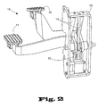
- FIG. 2 is a rear view drawing of the pedal assembly of FIG. 1 .
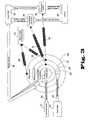
- FIG. 3 is an operations chart detailing the braking and acceleration of a rider surface maintenance vehicle.
- FIG. 4 is a plot of braking force versus time for various brake pedal positions.
- FIG. 5 is a plot of velocity versus time for various brake pedal positions, including a threshold velocity.
- an accelerator pedal (thought not limited to a pedal, such as a joystick or other responsive device) is employed to initiate for movement.
- the user depresses the accelerator by a physical amount, say 20%.
- the physical depression is converted into an electrical signal by a sensor, typically a Hall effect sensor, which is well-known in the art.
- An electrical signal representing 20% is sent to a controller circuit, which adjusts a voltage sent to the motor by the method of pulse-width-modulation (PWM).
- PWM pulse-width-modulation
- a voltage is sent in the form of pulses, with a frequency generally higher than the motor can respond, say at 2 KHz.
- a generally rectangular pulse is sent, with a low voltage (usually 0 volts) for a fraction of the pulse, then a high voltage (usually the battery voltage, say 24 volts) making up the rest of the pulse.
- the relative lengths of the low and high-voltage portions are expressed as a duty cycle. For instance, a pulse having a duty cycle of 20%, corresponding to our earlier example, would have a portion of 0 volts for 0.1 msec, followed by a portion of 24 volts for 0.4 msec.
- the controller circuit controls the duty cycle of the pulses in response to the physical depression of the accelerator pedal, from roughly 0% to roughly 100%. A physical depression of 0% would send effectively 0 volts to the motor.
- a physical depression of 100% would send the motor the maximum voltage, or 24 volts in our example.
- a physical depression of 50% would send the motor pulses made up of 0 volts for half the pulse length, then 24 volts for half the pulse length.
- the relationship between physical depression and duty cycle may be more complicated that the one-to-one correspondence cited in this example.
- the high voltage portion may precede the low voltage portion in the pulse. Note that in PWM of voltage, the only discrete voltages present are the high and low voltage levels, and that these two voltage levels drive the motor in a pulsed manner faster than the motor can respond, and that the rotation rate of the motor is determined by the relative lengths in each pulse of the low and high voltage periods or portions.
- FIGS. 1 and 2 show an embodiment of a pedal assembly 10 for a rider surface maintenance vehicle.
- An accelerator pedal 11 and a brake pedal 12 are each mechanically coupled to a pedal housing 13.
- the term “pedal” is not meant to be read as a limitation but can be any human interface device.
- a pair of expansion springs 14 provide a resisting force for the pedals 11 and 12, although other types of springs may be used, including compression springs, leaf springs and torsion springs.
- a pair of sensors 15 converts the mechanical positions of the pedals 11 and 12 into electrical signals, which are delivered to an electrical control system (not pictured) by an electrical interface 19.
- a suitable sensor 15 may be a Hall effect sensor, for example, although other sensors may be used to convert the mechanical pedal position into an electrical signal.
- the electrical signals may be analog and continuous in nature, with a property such as voltage, capacitance or resistance varying continuously in response to the pedal position.
- the electrical signals may be discrete in nature, with a property such as voltage, capacitance or resistance varying stepwise in response to the pedal position.
- the electrical signals may be a combination of continuous and discrete in nature, in that a property may vary continuously within a particular range, then may jump to another range once a particular threshold is reached.
- either or both of the electrical signals may have only one discrete level, meaning that the brake pedal, for instance, may be either "engaged” or "disengaged”.
- FIG. 3 shows an exemplary operations chart that provides a relationship among pedal positions, braking, vehicle velocity, and the flow of energy between the battery and the motor.
- the pedal positions are converted into electrical signals, which are then input via 23 and 24 to the acceleration and braking command modules 26 and 27, respectively.
- Those modules are part of a nested system of communication and control, which includes, from most general to most specific, a safety system 28, the braking command 27, the acceleration command 26 and a process control logic 25. All modules 25-28 in the nested system may preferably receive the actual velocity 38 of the vehicle as input.
- the acceleration command 26 Based on the operator accelerator input 23 and, optionally, the machine velocity 38, the acceleration command 26 produces an acceleration rate 31 either by dynamic calculation or by a lookup table, or a combination of calculation and lookup table.
- the acceleration rate 31 is used by the acceleration rate control 34 to propel the motor, denoted by 37 can be selected to give the user the feel of a mechanical braking system.
- the rider surface maintenance vehicle may preferably use pulse-width-modulation (PWM) on the voltage applied to the motor, where the pulses are generally applied at a higher frequency than the highest frequency at which the motor can respond (which may be referred to as the response frequency).
- PWM pulse-width-modulation
- the acceleration rate 31 is converted to a duty cycle for the pulses.
- the accelerator pedal 21 is depressed, the pedal position is converted to an electrical signal, which is passed via 23 to the acceleration command 26, which uses the pedal position and the machine velocity 38 to produce a duty cycle that is used in a PWM of the voltage that is sent to the motor.
- the motor speed is controlled, and the vehicle is propelled.
- acceleration rate control 34 other than PWM of the voltage may be used as well, including, but not limited to, pulse position modulation (PPM), in addition to generation of a generally pulse-free analog voltage sent to the motor.
- PPM pulse position modulation
- the acceleration rate 31 may be suitably converted to an appropriate quantity.
- the braking command 27 produces an machine deceleration rate 32, or braking rate, either by dynamic calculation or by a lookup table, or a combination of calculation and lookup table.
- the deceleration rate may be determined by a braking rate controller.
- the deceleration rate 32 is used by the braking rate control 35 to slow down the motor, and therefore, slow down the vehicle. The selection of the appropriate rate can provide the user with the feel of a mechanical braking system. Details of the deceleration rate 32 are explained further below.
- One possible braking rate control 35 is a PWM of the voltage sent to the motor, except with a reverse polarity. Given a deceleration rate 32, a duty cycle is calculated in the same manner as described above, and a PWM of a reverse-polarity voltage is sent to the motor. This method effectively turns the motor into a generator during the high-voltage reverse-polarity cycles, and recharges the battery 36. Use of a PWM of the voltage with reverse polarity can be called plug braking.
- a preferable braking rate control 35 is a PWM of the load or resistance across the motor.
- the pulses are generated at a frequency higher than the motor can respond, and a value of 2 KHz is typical, although the frequency may also be greater or less than 2 KHz.
- a low load i.e., a low conductance, or, equivalently, a high resistance
- a high load i.e., a high conductance, or, equivalently, a low resistance
- the resistances are generally applied in parallel to the electrical terminals on the motor.
- the duty cycle, or relative lengths of the low-load and high-load portions is determined in response to the machine deceleration rate 32, by a converter. For instance, the more the brake pedal 22 is depressed, the longer the high-load portion, and the shorter the low-load portion. It is found that PWM of the load across the motor may be more effective as a braking tool than plug braking, in that the motor may stop more quickly, thereby reducing the stopping distance of the vehicle and increasing safety.
- PPM pulse-position modulation
- Other possible braking rate controls 35 include pulse-position modulation (PPM), as well as use of a generally pulsed or non-pulsed analog or digital signal.
- PPM pulse-position modulation
- the operator controls the rate of braking, preferably by varying the position of the brake pedal 22. This may be referred to as variable dynamic braking, and may be contrasted with the fixed dynamic braking described above, in which the operator has no control over the rate of braking.
- dynamic braking may include as few as one discrete rate, corresponding to a pedal condition of "engaged”, in addition to the rate corresponding to "disengaged".
- the parking brake 30 may be in the form of a spring loaded mechanical brake 33, typically engaged by stopping the current through a solenoid in the brake mechanism. When the current stops, a spring loaded caliper brake pad is engaged. Use of the parking brake at these low velocities ensures that the vehicle may be safely parked on an incline, for example, without fear of drifting. In addition, when the vehicle is restarted from a stationary position, the parking brake 30 may be electronically disengaged, reducing the possibility of damage caused by driving with the parking brake 30 engaged.
- the safety system 28 may employ an emergency brake 29 if it detects a malfunction anywhere in the system.
- the emergency brake 29 typically may use the same spring loaded mechanical brake 33 as the parking brake. For instance, if the power is cut off, the current to the solenoid is stopped, and the spring loaded mechanical brake 33 is engaged. If an electrical defect is found in any of the signals, say the pulses are interrupted, then the default safety response is to engage the emergency brake 29, which is the spring loaded mechanical brake 33.
- This safety response is an improvement over a conventional mechanical braking system that uses a cable, in that in the event of a failure, the brake is engaged and the vehicle is brought to a halt.
- the machine deceleration rate 32 may be tuned to mimic or proximate the feel of the cabled system.
- Figure 4 shows an exemplary tuning scheme, in which the braking force is plotted against time, for nine different brake pedal positions. The case of the brake pedal completely released is denoted by item 40, items 41-47 represent increasingly depressed brake pedal positions, and item 48 denotes a fully depressed brake pedal.
- the set of curves shown in FIG. 4 may be adjusted as needed to increase the comfort level of the operator while suitably slowing down the vehicle. Note that the curves are determined by the machine deceleration rate 32 of FIG. 3 .
- FIG. 5 shows an exemplary plot of velocity against time, for nine different brake pedal positions 50-58.
- the brake pedal is completely released for 50, and completely depressed for 58.
- These curves are directly related to those in FIG. 4 , because the braking force is proportional to the time derivative of velocity.
- the threshold velocity 59 is shown as a dotted line in FIG. 5 , at which the parking brake 30 is engaged during stopping. Note that the curves in FIG. 5 are also determined by the machine deceleration rate 32 of FIG. 3 .
- the sensing of the velocity and pedal position, along with the determination of the braking rate, may be repeated at regular or irregular intervals, by an updater.
- the updater operates at a frequency greater than the response frequency of the motor so that the stopping motion is smooth and the user in unaware of the rapid updating of the braking function in response to velocity.
Landscapes
- Engineering & Computer Science (AREA)
- Transportation (AREA)
- Mechanical Engineering (AREA)
- Chemical & Material Sciences (AREA)
- Combustion & Propulsion (AREA)
- Physics & Mathematics (AREA)
- Electromagnetism (AREA)
- Power Engineering (AREA)
- Regulating Braking Force (AREA)
- Braking Systems And Boosters (AREA)
- Braking Elements And Transmission Devices (AREA)
- Braking Arrangements (AREA)
Abstract
Description
- The present invention is directed to surface cleaning equipment, and more particularly to a braking mechanism for surface cleaning equipment.
- Surface maintenance vehicles and cleaning devices have a long history subject to gradual innovation and improvement toward improved and oftentimes automated performance in removing debris and contamination from floors. These vehicles and devices may be self-powered, towed, or pushed, and/or manually powered and may carry a human operator during cleaning operations. Such vehicles and devices include scrubbers, extractors, sweepers and vacuums, as well as combinations thereof, intended for cleaning, scrubbing, wiping and/or drying a portion of a substantially flat surface both indoors and outdoors.
- A class of surface maintenance vehicles, known as riders, may contain an operator that drives the vehicle, using controls functionally similar to those in an automobile, including a steering wheel, an accelerator pedal and a brake pedal. As in an automobile, the accelerator and brake speed up and slow down the vehicle, but because the motor in a rider vehicle is typically electric, the methods by which the accelerator and brake function are usually quite different from those in an automobile.
- The braking on a typical rider surface maintenance vehicle is generally accomplished in a mechanical manner, using a brake cable to transmit a force from the brake pedal to one or more brake pads. Although a mechanical brake assembly provides the operator with a comfortable "feel" for braking, it is relatively expensive. A significant cost savings would be realized if the mechanical braking assembly were eliminated. Note that for safety concerns, it is not feasible to eliminate the brake pedal on a rider surface maintenance vehicle. (In contrast, a walk-behind machine may function without an additional brake, because the speeds are much less and the machines may be much smaller.)
- For safety reasons, a rider surface maintenance vehicle usually has a mechanical brake, typically in the form of a spring-loaded caliper brake pad, which is often referred to as a parking brake, which may or may not share a mechanism with the mechanical brake described above. Generally, the parking brake may be activated electronically by a solenoid, so that if the current to the solenoid is shut off, as may occur during a failure mechanism, then the parking brake is engaged. The use of a solenoid-activated spring-loaded caliper brake as a parking brake is well-known in the art. In addition, it is common to engage the parking brake when the accelerator pedal is released, when the vehicle velocity drops below a threshold value.
- Accordingly, there exists a need for a braking mechanism that costs less than a mechanical assembly, but still provides the operator with a proper braking "feel", and stops the vehicle in the event of a malfunction. Thus, since most operators are already familiar with the feel of a mechanical braking system, designing an electrical system which proximates (mimics) that feel is highly desirable.
US patent n. 4908553 describes a regenerative braking system useful in systems having variable kinetic energy such as vehicles. A DC machine having an independently energized field coil includes a rotor mechanically coupled for rotation at a speed proportional to the velocity of the load. During deceleration the armature is coupled to an inductor and rotational energy provided by the load is converted into magnetic energy stored in the magnetic field of the inductor. To store the energy a short is connected across the inductor, which is preferably operating under superconducting conditions. For acceleration this inductor current is applied to the DC machine to produce a torque for moving the load. The phase reversal required for proper direction of torque is preferably achieved by reversing the direction of field current. The rate of energy transfer and thus the rate of acceleration or deceleration is controlled by controlling the magnitude of the field coil current. A preferred embodiment includes a vehicle battery and motor control for powering the DC machine as the prime mover of the system. A control circuit responsive to vehicle speed, accelerator pedal position, brake pedal position, and the amount of current in the inductor controls switches for proper transfer of energy.
US patent n. 5340202 features an improved technique for slowing and stopping a vehicle having an electric service motor, a mechanical parking brake, and a deadman's switch for engaging the mechanical brake. The method of the invention improves the efficiency of the braking procedure. The braking method initially determines if the deadman's switch is engaged. If it is, then the electric service motor is plugged at a predetermined minimum plug rate until the vehicle slows to a specified velocity. When the specified velocity is reached, the plugging operation is terminated. The mechanical brake is then engaged to slow the vehicle to a halt. When the vehicle comes to a halt, the parking brake remains engaged. The invention also improves safety by increasing the controlled rate of plugging to a maximum value in the event that the deadman's switch is off. Actual braking performance by plugging is compared with that of accepted rates of deceleration or plugging effort shown by armature current to verify operation of the service braking system. In the event of inadequate service braking, such braking is terminated and the mechanical brake is applied.
GB patent n. 1376008 operable control members 25 each operably connected to an individual electrical component 18 forming part of one of the two independent speed controls of a pair ofdriving wheels 14, and synchronized movement of thecontrol members 25 adjusts the wheel speeds equally whereas differential movement provides a steering effect. - An embodiment is a method of providing an electrical braking function through an electrical motor in a surface maintenance vehicle to mimic the function of a mechanical braking system, comprising the steps of: engaging a brake pedal to initiate braking function; sensing the position of the brake pedal and encoding the pedal position as an electronic signal; sensing the vehicle velocity; using said vehicle velocity and said signal, determining a desired machine deceleration rate to approximate the sensation of mechanical braking; determining the desired conductance applied in parallel to the motor to create a dynamic braking force from the motor; and readjusting the conductance in response to deceleration to mimic the feel of mechanical braking, whereby the vehicle is decelerated.
- A further embodiment is a method of providing an electrical braking function through an electrical motor in a surface maintenance vehicle to mimic the function of a mechanical braking system, comprising the steps of: engaging a brake pedal to initiate braking function; sensing the position of the brake pedal and encoding the pedal position as an electronic signal; sensing the vehicle velocity; using said vehicle velocity and said signal, determining a desired machine deceleration rate to approximate the sensation of mechanical braking; generating a series of pulses of frequency greater than the response frequency of the motor; within each pulse defining the desired duty cycle to create an effective conductance; applying the effective conductance in parallel with the motor to cause machine deceleration by dynamic braking; and iteratively checking vehicle velocity and brake pedal position and correspondingly altering duty cycle to respond to demand for greater or lesser braking.
- A further embodiment is a method of providing an electrical braking function through an electrical motor in a surface maintenance vehicle to mimic the function of a mechanical braking system, comprising the steps of: engaging a brake pedal to initiate braking function; sensing the position of the brake pedal and encoding the pedal position as an electronic signal; sensing the vehicle velocity; using said vehicle velocity and said signal, determining a desired machine deceleration rate to approximate the sensation of mechanical braking; generating an analog signal in response to the deceleration rate; applying a voltage in response to the analog signal to the motor to cause machine deceleration by dynamic braking; and iteratively checking vehicle velocity and brake pedal position and correspondingly altering the voltage to respond to demand for greater or lesser braking.
- A further embodiment is an electrically powered surface maintenance machine with dynamic braking capable of mimicking mechanical braking, comprising: an electric motor; a brake pedal having a position sensor; an encoder for converting the pedal position to an electrical pedal position signal; a machine velocity sensor; a braking rate controller capable of determining braking force tuned to approximate mechanical braking, in response to the electrical pedal position signal and the machine velocity; a converter to translate braking rate to an effective electrical load to be applied in parallel to the motor; an updater for iteratively checking the machine velocity and the pedal position and repeatedly adjusting the braking rate and thereby adjusting the effective electrical load applied in parallel to the motor.
-
FIG. 1 is a front view drawing of a pedal assembly. -
FIG. 2 is a rear view drawing of the pedal assembly ofFIG. 1 . -
FIG. 3 is an operations chart detailing the braking and acceleration of a rider surface maintenance vehicle. -
FIG. 4 is a plot of braking force versus time for various brake pedal positions. -
FIG. 5 is a plot of velocity versus time for various brake pedal positions, including a threshold velocity. - In the present invention an accelerator pedal (thought not limited to a pedal, such as a joystick or other responsive device) is employed to initiate for movement. The user depresses the accelerator by a physical amount, say 20%. The physical depression is converted into an electrical signal by a sensor, typically a Hall effect sensor, which is well-known in the art. An electrical signal representing 20% is sent to a controller circuit, which adjusts a voltage sent to the motor by the method of pulse-width-modulation (PWM). In PWM, a voltage is sent in the form of pulses, with a frequency generally higher than the motor can respond, say at 2 KHz. Every 0.5 msec, a generally rectangular pulse is sent, with a low voltage (usually 0 volts) for a fraction of the pulse, then a high voltage (usually the battery voltage, say 24 volts) making up the rest of the pulse. The relative lengths of the low and high-voltage portions are expressed as a duty cycle. For instance, a pulse having a duty cycle of 20%, corresponding to our earlier example, would have a portion of 0 volts for 0.1 msec, followed by a portion of 24 volts for 0.4 msec. The controller circuit controls the duty cycle of the pulses in response to the physical depression of the accelerator pedal, from roughly 0% to roughly 100%. A physical depression of 0% would send effectively 0 volts to the motor. A physical depression of 100% would send the motor the maximum voltage, or 24 volts in our example. A physical depression of 50% would send the motor pulses made up of 0 volts for half the pulse length, then 24 volts for half the pulse length. Note that the relationship between physical depression and duty cycle may be more complicated that the one-to-one correspondence cited in this example. In addition, the high voltage portion may precede the low voltage portion in the pulse. Note that in PWM of voltage, the only discrete voltages present are the high and low voltage levels, and that these two voltage levels drive the motor in a pulsed manner faster than the motor can respond, and that the rotation rate of the motor is determined by the relative lengths in each pulse of the low and high voltage periods or portions.
- When the accelerator pedal is released, it is desirable that the vehicle come to deliberate stop (as opposed to coasting to a stop), requiring the use of a braking mechanism. We can achieve braking for an electric motor by applying a load across the motor, often by shorting out the motor. Recall that the required motor power P = V2 / R, and if R becomes effectively zero, then the motor would require effectively infinite power to turn, and therefore the motor stops. Simply shorting out the motor when the accelerator pedal is released is not appropriate; the motor and the vehicle would both stop abruptly, and the vehicle operator might suffer injury by colliding with the steering wheel or by being thrown off the vehicle. Using various techniques for varying the resistance/load/conductance across the motor, such as PWM of the load (or resistance) across the motor, where the conductance is kept at low (an open circuit) for a fraction of the pulse, then is raised to a high level (a short circuit) for the remainder of the pulse. In this manner, the vehicle may be stopped in a gradual manner, rather than an abrupt stop. Note that the high level portion may also precede the low level portion of the pulse. This "dynamic" or regenerative braking can be accomplished with PWM or other techniques. Typically, the duty cycle of the braking pulses applied when the accelerator pedal is released is set at the factory, meaning that when the operator releases the accelerator pedal, the vehicle brakes at a preset rate. We call this fixed dynamic braking, meaning that the operator has no control over the rate of the dynamic braking.
- Providing a braking system is more problematic since users are so familiar with mechanical systems. Mechanical braking systems have the advantage that the user gets immediate sensation of deceleration in response to increasing pedal pressure. Most electrical braking systems provide no real feedback and the user is likely to "overbrake" based on his/her experience with pedal feedback from mechanical systems. Short of providing a mechanical feedback system in the pedal to simulate pedal resistance in response to greater deceleration, which is incorporated herein as an option, it is still helpful to provide a way to correlate the change in dynamic braking to present velocity, deceleration and pedal position. This is the desired "feel" approximating the mechanical systems described in this application.
-
FIGS. 1 and2 show an embodiment of apedal assembly 10 for a rider surface maintenance vehicle. Anaccelerator pedal 11 and abrake pedal 12 are each mechanically coupled to apedal housing 13. (The term "pedal" is not meant to be read as a limitation but can be any human interface device.) A pair of expansion springs 14 provide a resisting force for thepedals sensors 15 converts the mechanical positions of thepedals electrical interface 19. Asuitable sensor 15 may be a Hall effect sensor, for example, although other sensors may be used to convert the mechanical pedal position into an electrical signal. Note that the electrical signals may be analog and continuous in nature, with a property such as voltage, capacitance or resistance varying continuously in response to the pedal position. Alternatively, the electrical signals may be discrete in nature, with a property such as voltage, capacitance or resistance varying stepwise in response to the pedal position. Alternatively, the electrical signals may be a combination of continuous and discrete in nature, in that a property may vary continuously within a particular range, then may jump to another range once a particular threshold is reached. As a further alternative, either or both of the electrical signals may have only one discrete level, meaning that the brake pedal, for instance, may be either "engaged" or "disengaged". -
FIG. 3 shows an exemplary operations chart that provides a relationship among pedal positions, braking, vehicle velocity, and the flow of energy between the battery and the motor. When an operator depresses theaccelerator pedal 21 or thebrake pedal 22, the pedal positions are converted into electrical signals, which are then input via 23 and 24 to the acceleration andbraking command modules safety system 28, thebraking command 27, theacceleration command 26 and aprocess control logic 25. All modules 25-28 in the nested system may preferably receive theactual velocity 38 of the vehicle as input. - Based on the
operator accelerator input 23 and, optionally, themachine velocity 38, theacceleration command 26 produces anacceleration rate 31 either by dynamic calculation or by a lookup table, or a combination of calculation and lookup table. Theacceleration rate 31 is used by theacceleration rate control 34 to propel the motor, denoted by 37 can be selected to give the user the feel of a mechanical braking system. - In order to control the motor speed, and therefore control the velocity of the machine, the rider surface maintenance vehicle may preferably use pulse-width-modulation (PWM) on the voltage applied to the motor, where the pulses are generally applied at a higher frequency than the highest frequency at which the motor can respond (which may be referred to as the response frequency). For use of PWM on the voltage, the
acceleration rate 31 is converted to a duty cycle for the pulses. In other words, theaccelerator pedal 21 is depressed, the pedal position is converted to an electrical signal, which is passed via 23 to theacceleration command 26, which uses the pedal position and themachine velocity 38 to produce a duty cycle that is used in a PWM of the voltage that is sent to the motor. Thereby, the motor speed is controlled, and the vehicle is propelled. It will be understood that other methods ofacceleration rate control 34 other than PWM of the voltage may be used as well, including, but not limited to, pulse position modulation (PPM), in addition to generation of a generally pulse-free analog voltage sent to the motor. For these other methods ofacceleration rate control 34, theacceleration rate 31 may be suitably converted to an appropriate quantity. - Based on the operator decelerator, or brake,
input 24, and optionally, themachine velocity 38 and/or theoperator accelerator input 23, thebraking command 27 produces anmachine deceleration rate 32, or braking rate, either by dynamic calculation or by a lookup table, or a combination of calculation and lookup table. The deceleration rate may be determined by a braking rate controller. Thedeceleration rate 32 is used by thebraking rate control 35 to slow down the motor, and therefore, slow down the vehicle. The selection of the appropriate rate can provide the user with the feel of a mechanical braking system. Details of thedeceleration rate 32 are explained further below. - One possible
braking rate control 35 is a PWM of the voltage sent to the motor, except with a reverse polarity. Given adeceleration rate 32, a duty cycle is calculated in the same manner as described above, and a PWM of a reverse-polarity voltage is sent to the motor. This method effectively turns the motor into a generator during the high-voltage reverse-polarity cycles, and recharges thebattery 36. Use of a PWM of the voltage with reverse polarity can be called plug braking. - A preferable
braking rate control 35 is a PWM of the load or resistance across the motor. The pulses are generated at a frequency higher than the motor can respond, and a value of 2 KHz is typical, although the frequency may also be greater or less than 2 KHz. During a portion of each pulse, a low load (i.e., a low conductance, or, equivalently, a high resistance) is sent to the motor, typically an open circuit. During the remainder of each pulse, a high load (i.e., a high conductance, or, equivalently, a low resistance) is sent to the motor, typically a short circuit. The resistances are generally applied in parallel to the electrical terminals on the motor. The duty cycle, or relative lengths of the low-load and high-load portions, is determined in response to themachine deceleration rate 32, by a converter. For instance, the more thebrake pedal 22 is depressed, the longer the high-load portion, and the shorter the low-load portion. It is found that PWM of the load across the motor may be more effective as a braking tool than plug braking, in that the motor may stop more quickly, thereby reducing the stopping distance of the vehicle and increasing safety. - Other possible braking rate controls 35 include pulse-position modulation (PPM), as well as use of a generally pulsed or non-pulsed analog or digital signal. Note that in any of the possible braking rate controls 35, the operator controls the rate of braking, preferably by varying the position of the
brake pedal 22. This may be referred to as variable dynamic braking, and may be contrasted with the fixed dynamic braking described above, in which the operator has no control over the rate of braking. Note that dynamic braking may include as few as one discrete rate, corresponding to a pedal condition of "engaged", in addition to the rate corresponding to "disengaged". - During braking, as the vehicle's velocity drops below a certain threshold, the
braking command 27 infers that the operator intends to stop the vehicle and automatically engages aparking brake 30. Theparking brake 30 may be in the form of a spring loadedmechanical brake 33, typically engaged by stopping the current through a solenoid in the brake mechanism. When the current stops, a spring loaded caliper brake pad is engaged. Use of the parking brake at these low velocities ensures that the vehicle may be safely parked on an incline, for example, without fear of drifting. In addition, when the vehicle is restarted from a stationary position, theparking brake 30 may be electronically disengaged, reducing the possibility of damage caused by driving with theparking brake 30 engaged. - The
safety system 28 may employ anemergency brake 29 if it detects a malfunction anywhere in the system. Theemergency brake 29 typically may use the same spring loadedmechanical brake 33 as the parking brake. For instance, if the power is cut off, the current to the solenoid is stopped, and the spring loadedmechanical brake 33 is engaged. If an electrical defect is found in any of the signals, say the pulses are interrupted, then the default safety response is to engage theemergency brake 29, which is the spring loadedmechanical brake 33. This safety response is an improvement over a conventional mechanical braking system that uses a cable, in that in the event of a failure, the brake is engaged and the vehicle is brought to a halt. - It is desirable that the operator feel a particular level of comfort applying the brake, comparable with the familiar feel of a cabled mechanical brake system found in other vehicles. Preferably, the brake should approximate the sensation of a common mechanical brake system. Because of the electronic nature of the braking system, the
machine deceleration rate 32 may be tuned to mimic or proximate the feel of the cabled system.Figure 4 shows an exemplary tuning scheme, in which the braking force is plotted against time, for nine different brake pedal positions. The case of the brake pedal completely released is denoted byitem 40, items 41-47 represent increasingly depressed brake pedal positions, anditem 48 denotes a fully depressed brake pedal. The set of curves shown inFIG. 4 may be adjusted as needed to increase the comfort level of the operator while suitably slowing down the vehicle. Note that the curves are determined by themachine deceleration rate 32 ofFIG. 3 . - Similarly,
FIG. 5 shows an exemplary plot of velocity against time, for nine different brake pedal positions 50-58. The brake pedal is completely released for 50, and completely depressed for 58. These curves are directly related to those inFIG. 4 , because the braking force is proportional to the time derivative of velocity. Thethreshold velocity 59 is shown as a dotted line inFIG. 5 , at which theparking brake 30 is engaged during stopping. Note that the curves inFIG. 5 are also determined by themachine deceleration rate 32 ofFIG. 3 . - The sensing of the velocity and pedal position, along with the determination of the braking rate, may be repeated at regular or irregular intervals, by an updater. Preferably, the updater operates at a frequency greater than the response frequency of the motor so that the stopping motion is smooth and the user in unaware of the rapid updating of the braking function in response to velocity.
- The description of the invention and its applications as set forth herein is illustrative and is not intended to limit the scope of the invention. Variations and modifications of the embodiments disclosed herein are possible, and practical alternatives to and equivalents of the various elements of the embodiments would be understood to those of ordinary skill in the art upon study of this patent document. These and other variations and modifications of the embodiments disclosed herein may be made without departing from the scope of the invention.
Claims (7)
- A method of providing an electrical braking function through an electrical motor (37) in a surface maintenance vehicle to approximate the feel of a mechanical braking system, comprisinga. engaging a brake pedal (12;22) to initiate braking function;b. sensing the position of the brake pedal (12;22) and encoding the pedal position as an electronic signal;c. sensing the vehicle velocity (38);
characterized ind. using said vehicle velocity (38) and said signal, determining a desired machine deceleration rate to approximate the sensation of mechanical braking, said deceleration rate (32) being determined by a braking rate controller determining a plurality of curves in which the braking force is plotted against time, for different brake pedal positions, said curves being used as a tuning scheme to mimic or proximate the feel of the mechanical system;e. determining the desired conductance applied in parallel to the motor to create a dynamic braking force from the motor (37); andf. iteratively checking vehicle velocity and brake pedal position and correspondingly pulse width modulating the duty cycle to respond to demand for greater or lesser braking to maintain the sensation of mechanical braking. - The method of claim 1, wherein the determining step is performed by calculation.
- The method of claim 1, wherein the determining step is performed by lookup table.
- The method of claim 1, wherein the determining step is performed by a combination of calculation and lookup table.
- The method of claim 1, wherein the amplitude of each pulse is essentially constant and does not vary with duty cycle.
- The method of claim 1, wherein if the sensed vehicle velocity is below a predetermined threshold velocity, then a parking brake (30) is engaged.
- The method of claim 6, wherein the parking brake (30) is a solenoid-driven spring-loaded caliper brake pad (33).
Applications Claiming Priority (3)
| Application Number | Priority Date | Filing Date | Title |
|---|---|---|---|
| US55088504P | 2004-03-05 | 2004-03-05 | |
| PCT/US2005/007325 WO2005086758A2 (en) | 2004-03-05 | 2005-03-07 | By wire control of braking and acceleration |
| US11/073,785 US7244000B2 (en) | 2004-03-05 | 2005-03-07 | By wire control of braking and acceleration |
Publications (3)
| Publication Number | Publication Date |
|---|---|
| EP1727718A2 EP1727718A2 (en) | 2006-12-06 |
| EP1727718A4 EP1727718A4 (en) | 2009-04-22 |
| EP1727718B1 true EP1727718B1 (en) | 2011-05-04 |
Family
ID=34915202
Family Applications (1)
| Application Number | Title | Priority Date | Filing Date |
|---|---|---|---|
| EP05724795A Expired - Lifetime EP1727718B1 (en) | 2004-03-05 | 2005-03-07 | Electrical braking method and system |
Country Status (5)
| Country | Link |
|---|---|
| US (2) | US7244000B2 (en) |
| EP (1) | EP1727718B1 (en) |
| AT (1) | ATE508000T1 (en) |
| DE (1) | DE602005027823D1 (en) |
| WO (1) | WO2005086758A2 (en) |
Families Citing this family (7)
| Publication number | Priority date | Publication date | Assignee | Title |
|---|---|---|---|---|
| DE602005027823D1 (en) * | 2004-03-05 | 2011-06-16 | Tennant Minneapolis | ELECTRIC BRAKING CONTROL |
| DE102014221835A1 (en) * | 2014-10-27 | 2016-04-28 | Ford Global Technologies, Llc | Method and device for vehicle control |
| KR102492487B1 (en) * | 2018-08-16 | 2023-01-27 | 현대모비스 주식회사 | Apparatus for braking of vehicle and method thereof |
| US12115882B2 (en) * | 2021-06-29 | 2024-10-15 | Dana Italia S.R.L. | Method and system for vehicle braking |
| CN114397111B (en) * | 2021-12-15 | 2023-04-07 | 安徽江淮汽车集团股份有限公司 | Passenger vehicle brake pedal sensing test method |
| US12227161B2 (en) | 2022-02-24 | 2025-02-18 | Deere & Company | Brake pedal feedback system |
| DE102022110059A1 (en) * | 2022-04-26 | 2023-10-26 | Audi Aktiengesellschaft | Method for operating a brake system for a motor vehicle and corresponding brake system |
Family Cites Families (9)
| Publication number | Priority date | Publication date | Assignee | Title |
|---|---|---|---|---|
| GB1376008A (en) * | 1972-09-12 | 1974-12-04 | Dixon Co Ltd R G | Floor treating machines |
| US4908553A (en) | 1988-12-20 | 1990-03-13 | Eaton Corporation | Magnetic regenerative braking system |
| US5340202A (en) | 1991-10-30 | 1994-08-23 | Raymond Corporation | Service braking technique for material handling vehicles |
| US6220379B1 (en) * | 1996-02-13 | 2001-04-24 | Dane Industries, Inc. | Cart retriever vehicle |
| US5977740A (en) * | 1997-05-14 | 1999-11-02 | Itt Manufacturing Enterprises, Inc. | Brake-by-wire system with switched reluctance motor controller |
| DE69836301T2 (en) * | 1997-07-29 | 2007-06-06 | Toyota Jidosha Kabushiki Kaisha, Toyota | Electrically operated brake system with an electric brake motor actuator for obtaining a relationship between engine power and braking torque |
| US6462506B2 (en) * | 1999-12-30 | 2002-10-08 | Textron Inc. | Electric golf car with low-speed regenerative braking |
| JP4154883B2 (en) * | 2001-11-01 | 2008-09-24 | 株式会社日立製作所 | Brake device |
| DE602005027823D1 (en) * | 2004-03-05 | 2011-06-16 | Tennant Minneapolis | ELECTRIC BRAKING CONTROL |
-
2005
- 2005-03-07 DE DE602005027823T patent/DE602005027823D1/en active Active
- 2005-03-07 AT AT05724795T patent/ATE508000T1/en not_active IP Right Cessation
- 2005-03-07 WO PCT/US2005/007325 patent/WO2005086758A2/en not_active Ceased
- 2005-03-07 EP EP05724795A patent/EP1727718B1/en not_active Expired - Lifetime
- 2005-03-07 US US11/073,785 patent/US7244000B2/en not_active Expired - Lifetime
-
2007
- 2007-07-10 US US11/775,399 patent/US20070284160A1/en not_active Abandoned
Also Published As
| Publication number | Publication date |
|---|---|
| EP1727718A2 (en) | 2006-12-06 |
| WO2005086758A2 (en) | 2005-09-22 |
| US20050194837A1 (en) | 2005-09-08 |
| US20070284160A1 (en) | 2007-12-13 |
| DE602005027823D1 (en) | 2011-06-16 |
| EP1727718A4 (en) | 2009-04-22 |
| ATE508000T1 (en) | 2011-05-15 |
| US7244000B2 (en) | 2007-07-17 |
| WO2005086758A3 (en) | 2006-07-13 |
Similar Documents
| Publication | Publication Date | Title |
|---|---|---|
| US20070284160A1 (en) | By wire control of braking and acceleration | |
| US6454033B1 (en) | Electro-hydraulic vehicle with energy regeneration | |
| US4671577A (en) | Combined regenerative and friction braking system for a vehicle | |
| JP3811373B2 (en) | Variable current limiting control device and vehicle electric drive system | |
| US5764009A (en) | Motor control device in electric motor-operated vehicle | |
| JP4620709B2 (en) | In-vehicle actuator system | |
| AU771098B2 (en) | Blended electrical/friction braking system with electric brake feedback monitor and method of use thereof | |
| US4730151A (en) | Continuous field control of series wound motors | |
| US4906906A (en) | Conveyance with electronic control for left and right motors | |
| EP0585122B1 (en) | Control device for electric vehicles | |
| US8165747B2 (en) | Pedal system and vehicle with the pedal system | |
| EP2314473A2 (en) | Regenerative braking system for an electric vehicle | |
| EP0870641B1 (en) | Performance event sensing for control of electric motor driven golf car | |
| AU8514598A (en) | Direct current electric vehicle drive | |
| EP0921028A2 (en) | Electric motor rotor holding arrangement | |
| KR970010302A (en) | Control device of electric car | |
| US4658189A (en) | Series connected series motors for independent loads | |
| CN109476297A (en) | Electric Brakes and Electric Brake Systems | |
| CN110901618B (en) | Apparatus and method for operating an electric parking brake of a vehicle | |
| US4672811A (en) | Vehicle speed control system | |
| US3597669A (en) | Electrical braking system for electric motor-driven vehicles | |
| GB1416636A (en) | Driving arrangement for an electrically propelled vehicle | |
| KR890002127B1 (en) | Traction drive | |
| Ozdemir et al. | Fuzzy control of traction motor in light metro vehicle | |
| JP3743367B2 (en) | Automatic vehicle speed control device |
Legal Events
| Date | Code | Title | Description |
|---|---|---|---|
| PUAI | Public reference made under article 153(3) epc to a published international application that has entered the european phase |
Free format text: ORIGINAL CODE: 0009012 |
|
| 17P | Request for examination filed |
Effective date: 20060929 |
|
| AK | Designated contracting states |
Kind code of ref document: A2 Designated state(s): AT BE BG CH CY CZ DE DK EE ES FI FR GB GR HU IE IS IT LI LT LU MC NL PL PT RO SE SI SK TR |
|
| AX | Request for extension of the european patent |
Extension state: AL BA HR LV MK YU |
|
| DAX | Request for extension of the european patent (deleted) | ||
| A4 | Supplementary search report drawn up and despatched |
Effective date: 20090324 |
|
| RIC1 | Information provided on ipc code assigned before grant |
Ipc: B60T 13/58 20060101ALI20090318BHEP Ipc: B60T 13/74 20060101ALI20090318BHEP Ipc: B60L 7/00 20060101AFI20090318BHEP Ipc: A47L 11/00 20060101ALI20090318BHEP |
|
| 17Q | First examination report despatched |
Effective date: 20090706 |
|
| RTI1 | Title (correction) |
Free format text: ELECTRICAL BRAKING METHOD AND SYSTEM |
|
| GRAP | Despatch of communication of intention to grant a patent |
Free format text: ORIGINAL CODE: EPIDOSNIGR1 |
|
| GRAS | Grant fee paid |
Free format text: ORIGINAL CODE: EPIDOSNIGR3 |
|
| GRAA | (expected) grant |
Free format text: ORIGINAL CODE: 0009210 |
|
| AK | Designated contracting states |
Kind code of ref document: B1 Designated state(s): AT BE BG CH CY CZ DE DK EE ES FI FR GB GR HU IE IS IT LI LT LU MC NL PL PT RO SE SI SK TR |
|
| REG | Reference to a national code |
Ref country code: GB Ref legal event code: FG4D |
|
| REG | Reference to a national code |
Ref country code: CH Ref legal event code: EP |
|
| REG | Reference to a national code |
Ref country code: IE Ref legal event code: FG4D |
|
| REF | Corresponds to: |
Ref document number: 602005027823 Country of ref document: DE Date of ref document: 20110616 Kind code of ref document: P |
|
| REG | Reference to a national code |
Ref country code: DE Ref legal event code: R096 Ref document number: 602005027823 Country of ref document: DE Effective date: 20110616 |
|
| REG | Reference to a national code |
Ref country code: NL Ref legal event code: VDEP Effective date: 20110504 |
|
| PG25 | Lapsed in a contracting state [announced via postgrant information from national office to epo] |
Ref country code: LT Free format text: LAPSE BECAUSE OF FAILURE TO SUBMIT A TRANSLATION OF THE DESCRIPTION OR TO PAY THE FEE WITHIN THE PRESCRIBED TIME-LIMIT Effective date: 20110504 Ref country code: PT Free format text: LAPSE BECAUSE OF FAILURE TO SUBMIT A TRANSLATION OF THE DESCRIPTION OR TO PAY THE FEE WITHIN THE PRESCRIBED TIME-LIMIT Effective date: 20110905 Ref country code: SE Free format text: LAPSE BECAUSE OF FAILURE TO SUBMIT A TRANSLATION OF THE DESCRIPTION OR TO PAY THE FEE WITHIN THE PRESCRIBED TIME-LIMIT Effective date: 20110504 |
|
| PG25 | Lapsed in a contracting state [announced via postgrant information from national office to epo] |
Ref country code: CY Free format text: LAPSE BECAUSE OF FAILURE TO SUBMIT A TRANSLATION OF THE DESCRIPTION OR TO PAY THE FEE WITHIN THE PRESCRIBED TIME-LIMIT Effective date: 20110504 Ref country code: ES Free format text: LAPSE BECAUSE OF FAILURE TO SUBMIT A TRANSLATION OF THE DESCRIPTION OR TO PAY THE FEE WITHIN THE PRESCRIBED TIME-LIMIT Effective date: 20110815 Ref country code: FI Free format text: LAPSE BECAUSE OF FAILURE TO SUBMIT A TRANSLATION OF THE DESCRIPTION OR TO PAY THE FEE WITHIN THE PRESCRIBED TIME-LIMIT Effective date: 20110504 Ref country code: BE Free format text: LAPSE BECAUSE OF FAILURE TO SUBMIT A TRANSLATION OF THE DESCRIPTION OR TO PAY THE FEE WITHIN THE PRESCRIBED TIME-LIMIT Effective date: 20110504 Ref country code: SI Free format text: LAPSE BECAUSE OF FAILURE TO SUBMIT A TRANSLATION OF THE DESCRIPTION OR TO PAY THE FEE WITHIN THE PRESCRIBED TIME-LIMIT Effective date: 20110504 Ref country code: IS Free format text: LAPSE BECAUSE OF FAILURE TO SUBMIT A TRANSLATION OF THE DESCRIPTION OR TO PAY THE FEE WITHIN THE PRESCRIBED TIME-LIMIT Effective date: 20110904 Ref country code: AT Free format text: LAPSE BECAUSE OF FAILURE TO SUBMIT A TRANSLATION OF THE DESCRIPTION OR TO PAY THE FEE WITHIN THE PRESCRIBED TIME-LIMIT Effective date: 20110504 Ref country code: GR Free format text: LAPSE BECAUSE OF FAILURE TO SUBMIT A TRANSLATION OF THE DESCRIPTION OR TO PAY THE FEE WITHIN THE PRESCRIBED TIME-LIMIT Effective date: 20110805 |
|
| PG25 | Lapsed in a contracting state [announced via postgrant information from national office to epo] |
Ref country code: NL Free format text: LAPSE BECAUSE OF FAILURE TO SUBMIT A TRANSLATION OF THE DESCRIPTION OR TO PAY THE FEE WITHIN THE PRESCRIBED TIME-LIMIT Effective date: 20110504 |
|
| PG25 | Lapsed in a contracting state [announced via postgrant information from national office to epo] |
Ref country code: EE Free format text: LAPSE BECAUSE OF FAILURE TO SUBMIT A TRANSLATION OF THE DESCRIPTION OR TO PAY THE FEE WITHIN THE PRESCRIBED TIME-LIMIT Effective date: 20110504 Ref country code: CZ Free format text: LAPSE BECAUSE OF FAILURE TO SUBMIT A TRANSLATION OF THE DESCRIPTION OR TO PAY THE FEE WITHIN THE PRESCRIBED TIME-LIMIT Effective date: 20110504 |
|
| PG25 | Lapsed in a contracting state [announced via postgrant information from national office to epo] |
Ref country code: PL Free format text: LAPSE BECAUSE OF FAILURE TO SUBMIT A TRANSLATION OF THE DESCRIPTION OR TO PAY THE FEE WITHIN THE PRESCRIBED TIME-LIMIT Effective date: 20110504 Ref country code: DK Free format text: LAPSE BECAUSE OF FAILURE TO SUBMIT A TRANSLATION OF THE DESCRIPTION OR TO PAY THE FEE WITHIN THE PRESCRIBED TIME-LIMIT Effective date: 20110504 Ref country code: RO Free format text: LAPSE BECAUSE OF FAILURE TO SUBMIT A TRANSLATION OF THE DESCRIPTION OR TO PAY THE FEE WITHIN THE PRESCRIBED TIME-LIMIT Effective date: 20110504 Ref country code: SK Free format text: LAPSE BECAUSE OF FAILURE TO SUBMIT A TRANSLATION OF THE DESCRIPTION OR TO PAY THE FEE WITHIN THE PRESCRIBED TIME-LIMIT Effective date: 20110504 |
|
| PLBE | No opposition filed within time limit |
Free format text: ORIGINAL CODE: 0009261 |
|
| STAA | Information on the status of an ep patent application or granted ep patent |
Free format text: STATUS: NO OPPOSITION FILED WITHIN TIME LIMIT |
|
| 26N | No opposition filed |
Effective date: 20120207 |
|
| REG | Reference to a national code |
Ref country code: DE Ref legal event code: R097 Ref document number: 602005027823 Country of ref document: DE Effective date: 20120207 |
|
| PG25 | Lapsed in a contracting state [announced via postgrant information from national office to epo] |
Ref country code: MC Free format text: LAPSE BECAUSE OF NON-PAYMENT OF DUE FEES Effective date: 20120331 |
|
| REG | Reference to a national code |
Ref country code: CH Ref legal event code: PL |
|
| REG | Reference to a national code |
Ref country code: IE Ref legal event code: MM4A |
|
| PG25 | Lapsed in a contracting state [announced via postgrant information from national office to epo] |
Ref country code: IE Free format text: LAPSE BECAUSE OF NON-PAYMENT OF DUE FEES Effective date: 20120307 Ref country code: LI Free format text: LAPSE BECAUSE OF NON-PAYMENT OF DUE FEES Effective date: 20120331 Ref country code: CH Free format text: LAPSE BECAUSE OF NON-PAYMENT OF DUE FEES Effective date: 20120331 |
|
| PG25 | Lapsed in a contracting state [announced via postgrant information from national office to epo] |
Ref country code: BG Free format text: LAPSE BECAUSE OF FAILURE TO SUBMIT A TRANSLATION OF THE DESCRIPTION OR TO PAY THE FEE WITHIN THE PRESCRIBED TIME-LIMIT Effective date: 20110804 |
|
| PG25 | Lapsed in a contracting state [announced via postgrant information from national office to epo] |
Ref country code: TR Free format text: LAPSE BECAUSE OF FAILURE TO SUBMIT A TRANSLATION OF THE DESCRIPTION OR TO PAY THE FEE WITHIN THE PRESCRIBED TIME-LIMIT Effective date: 20110504 |
|
| PG25 | Lapsed in a contracting state [announced via postgrant information from national office to epo] |
Ref country code: LU Free format text: LAPSE BECAUSE OF NON-PAYMENT OF DUE FEES Effective date: 20120307 |
|
| PG25 | Lapsed in a contracting state [announced via postgrant information from national office to epo] |
Ref country code: HU Free format text: LAPSE BECAUSE OF FAILURE TO SUBMIT A TRANSLATION OF THE DESCRIPTION OR TO PAY THE FEE WITHIN THE PRESCRIBED TIME-LIMIT Effective date: 20050307 |
|
| REG | Reference to a national code |
Ref country code: FR Ref legal event code: PLFP Year of fee payment: 12 |
|
| REG | Reference to a national code |
Ref country code: FR Ref legal event code: PLFP Year of fee payment: 13 |
|
| REG | Reference to a national code |
Ref country code: FR Ref legal event code: PLFP Year of fee payment: 14 |
|
| PGFP | Annual fee paid to national office [announced via postgrant information from national office to epo] |
Ref country code: GB Payment date: 20180327 Year of fee payment: 14 |
|
| PGFP | Annual fee paid to national office [announced via postgrant information from national office to epo] |
Ref country code: FR Payment date: 20180326 Year of fee payment: 14 Ref country code: IT Payment date: 20180322 Year of fee payment: 14 |
|
| PGFP | Annual fee paid to national office [announced via postgrant information from national office to epo] |
Ref country code: DE Payment date: 20180328 Year of fee payment: 14 |
|
| REG | Reference to a national code |
Ref country code: DE Ref legal event code: R119 Ref document number: 602005027823 Country of ref document: DE |
|
| GBPC | Gb: european patent ceased through non-payment of renewal fee |
Effective date: 20190307 |
|
| PG25 | Lapsed in a contracting state [announced via postgrant information from national office to epo] |
Ref country code: GB Free format text: LAPSE BECAUSE OF NON-PAYMENT OF DUE FEES Effective date: 20190307 Ref country code: DE Free format text: LAPSE BECAUSE OF NON-PAYMENT OF DUE FEES Effective date: 20191001 |
|
| PG25 | Lapsed in a contracting state [announced via postgrant information from national office to epo] |
Ref country code: IT Free format text: LAPSE BECAUSE OF NON-PAYMENT OF DUE FEES Effective date: 20190307 Ref country code: FR Free format text: LAPSE BECAUSE OF NON-PAYMENT OF DUE FEES Effective date: 20190331 |