EP0870641B1 - Performance event sensing for control of electric motor driven golf car - Google Patents
Performance event sensing for control of electric motor driven golf car Download PDFInfo
- Publication number
- EP0870641B1 EP0870641B1 EP98302817A EP98302817A EP0870641B1 EP 0870641 B1 EP0870641 B1 EP 0870641B1 EP 98302817 A EP98302817 A EP 98302817A EP 98302817 A EP98302817 A EP 98302817A EP 0870641 B1 EP0870641 B1 EP 0870641B1
- Authority
- EP
- European Patent Office
- Prior art keywords
- speed
- armature
- signal
- field current
- zero
- Prior art date
- Legal status (The legal status is an assumption and is not a legal conclusion. Google has not performed a legal analysis and makes no representation as to the accuracy of the status listed.)
- Expired - Lifetime
Links
Images


Classifications
-
- B—PERFORMING OPERATIONS; TRANSPORTING
- B60—VEHICLES IN GENERAL
- B60L—PROPULSION OF ELECTRICALLY-PROPELLED VEHICLES; SUPPLYING ELECTRIC POWER FOR AUXILIARY EQUIPMENT OF ELECTRICALLY-PROPELLED VEHICLES; ELECTRODYNAMIC BRAKE SYSTEMS FOR VEHICLES IN GENERAL; MAGNETIC SUSPENSION OR LEVITATION FOR VEHICLES; MONITORING OPERATING VARIABLES OF ELECTRICALLY-PROPELLED VEHICLES; ELECTRIC SAFETY DEVICES FOR ELECTRICALLY-PROPELLED VEHICLES
- B60L15/00—Methods, circuits, or devices for controlling the traction-motor speed of electrically-propelled vehicles
- B60L15/20—Methods, circuits, or devices for controlling the traction-motor speed of electrically-propelled vehicles for control of the vehicle or its driving motor to achieve a desired performance, e.g. speed, torque, programmed variation of speed
- B60L15/2009—Methods, circuits, or devices for controlling the traction-motor speed of electrically-propelled vehicles for control of the vehicle or its driving motor to achieve a desired performance, e.g. speed, torque, programmed variation of speed for braking
-
- B—PERFORMING OPERATIONS; TRANSPORTING
- B60—VEHICLES IN GENERAL
- B60L—PROPULSION OF ELECTRICALLY-PROPELLED VEHICLES; SUPPLYING ELECTRIC POWER FOR AUXILIARY EQUIPMENT OF ELECTRICALLY-PROPELLED VEHICLES; ELECTRODYNAMIC BRAKE SYSTEMS FOR VEHICLES IN GENERAL; MAGNETIC SUSPENSION OR LEVITATION FOR VEHICLES; MONITORING OPERATING VARIABLES OF ELECTRICALLY-PROPELLED VEHICLES; ELECTRIC SAFETY DEVICES FOR ELECTRICALLY-PROPELLED VEHICLES
- B60L50/00—Electric propulsion with power supplied within the vehicle
- B60L50/50—Electric propulsion with power supplied within the vehicle using propulsion power supplied by batteries or fuel cells
- B60L50/52—Electric propulsion with power supplied within the vehicle using propulsion power supplied by batteries or fuel cells characterised by DC-motors
-
- B—PERFORMING OPERATIONS; TRANSPORTING
- B60—VEHICLES IN GENERAL
- B60L—PROPULSION OF ELECTRICALLY-PROPELLED VEHICLES; SUPPLYING ELECTRIC POWER FOR AUXILIARY EQUIPMENT OF ELECTRICALLY-PROPELLED VEHICLES; ELECTRODYNAMIC BRAKE SYSTEMS FOR VEHICLES IN GENERAL; MAGNETIC SUSPENSION OR LEVITATION FOR VEHICLES; MONITORING OPERATING VARIABLES OF ELECTRICALLY-PROPELLED VEHICLES; ELECTRIC SAFETY DEVICES FOR ELECTRICALLY-PROPELLED VEHICLES
- B60L2200/00—Type of vehicles
- B60L2200/22—Microcars, e.g. golf cars
-
- Y—GENERAL TAGGING OF NEW TECHNOLOGICAL DEVELOPMENTS; GENERAL TAGGING OF CROSS-SECTIONAL TECHNOLOGIES SPANNING OVER SEVERAL SECTIONS OF THE IPC; TECHNICAL SUBJECTS COVERED BY FORMER USPC CROSS-REFERENCE ART COLLECTIONS [XRACs] AND DIGESTS
- Y02—TECHNOLOGIES OR APPLICATIONS FOR MITIGATION OR ADAPTATION AGAINST CLIMATE CHANGE
- Y02T—CLIMATE CHANGE MITIGATION TECHNOLOGIES RELATED TO TRANSPORTATION
- Y02T10/00—Road transport of goods or passengers
- Y02T10/60—Other road transportation technologies with climate change mitigation effect
- Y02T10/64—Electric machine technologies in electromobility
-
- Y—GENERAL TAGGING OF NEW TECHNOLOGICAL DEVELOPMENTS; GENERAL TAGGING OF CROSS-SECTIONAL TECHNOLOGIES SPANNING OVER SEVERAL SECTIONS OF THE IPC; TECHNICAL SUBJECTS COVERED BY FORMER USPC CROSS-REFERENCE ART COLLECTIONS [XRACs] AND DIGESTS
- Y02—TECHNOLOGIES OR APPLICATIONS FOR MITIGATION OR ADAPTATION AGAINST CLIMATE CHANGE
- Y02T—CLIMATE CHANGE MITIGATION TECHNOLOGIES RELATED TO TRANSPORTATION
- Y02T10/00—Road transport of goods or passengers
- Y02T10/60—Other road transportation technologies with climate change mitigation effect
- Y02T10/70—Energy storage systems for electromobility, e.g. batteries
-
- Y—GENERAL TAGGING OF NEW TECHNOLOGICAL DEVELOPMENTS; GENERAL TAGGING OF CROSS-SECTIONAL TECHNOLOGIES SPANNING OVER SEVERAL SECTIONS OF THE IPC; TECHNICAL SUBJECTS COVERED BY FORMER USPC CROSS-REFERENCE ART COLLECTIONS [XRACs] AND DIGESTS
- Y02—TECHNOLOGIES OR APPLICATIONS FOR MITIGATION OR ADAPTATION AGAINST CLIMATE CHANGE
- Y02T—CLIMATE CHANGE MITIGATION TECHNOLOGIES RELATED TO TRANSPORTATION
- Y02T10/00—Road transport of goods or passengers
- Y02T10/60—Other road transportation technologies with climate change mitigation effect
- Y02T10/72—Electric energy management in electromobility
Definitions
- Electric motor driven vehicles in particular golf cars, have many unique performance requirements that pose difficult obstacles to the design of control systems for direct current motors used as the primary means of propulsion.
- Shunt motors tend to have a characteristic response curve, namely a specific speed for a specific load. This is a result of a balancing of the input voltage and the back emf generated by the motion of the motor armature through the magnetic field established by the energized field coil. Speed and torque can be conveniently controlled by the adjustment of the voltage or current across or in either the armature or the field winding or both.
- motor control can be obtained through either the armature current or the field current, it is advantageous to rely on the variation of field current because of the lower current levels.
- the use of field current enables the use of low power, less expensive components that increase efficiency. It is the purpose of a preferred embodiment of this invention to provide a system of control which allows operation of the motor along its full range of response characteristics in accordance with a particular armature current to field current map.
- Basic speed control for such motors involves the use of a chopper circuit to supply pulses of voltage to the armature which are varied in duty cycle from 0 to 100% according to the desired speed in response to the manually operated throttle. Further refinement of the control is provided by an H bridge circuit operatively connected to vary the current in the field winding. These circuits are well known in the art.
- Regenerative braking involves the use of the back emf generated in the armature to retard rotation of the armature and therefore the speed of the golf car.
- Dynamic braking is accomplished by reversing the field current and dissipating the resultant energy generated as the armature rotation slows to a stop.
- a system is provided in one example for controlling a D-C motor which is constructed to propel a golf car.
- the motor is controlled to provide performance according to a predetermined field current map which calls for a particular performance response to specified performance events.
- the performance events are detected by sensing actual speed and armature current and the performance response is triggered by adjustment of the field current or other appropriate parameters.
- a performance map correlating actual speed to various events and specifying the field current response is designed for the motor used.
- an armature current performance map is similarly constructed correlating armature current to particular performance events.
- a selection of performance maps are provided which are designed for specific types of terrain, for example, level ground, all-terrain, small to medium grades, and steep grades.
- the motor is a shunt wound motor having independently excited armature and field windings.
- the basic input to the armature of the motor is supplied through a pulse width modulated chopper circuit which varies the width of its output voltage pulse (duty cycle) in response to the throttle of the golf car.
- Full control of the input to the field winding is gained by the supply of power to an H bridge circuit.
- Armature current is continuously sensed to provide an indication of the status and performance of the car during operation. In addition actual speed of the golf car is sensed. At a predetermined level of armature current indicative of going up a hill, the field current is adjusted to provide a higher torque at a specific speed.
- sensed speed indicates a predetermined over speed condition, as for example when the vehicle coasts, field current is increased to enhance regeneration and the resultant braking.
- a predetermined delay is initiated and if the speed sensor indicates thereafter, that the vehicle has begun to roll, an appropriate field current can be applied to limit the speed of the car.
- the at rest condition is continuously monitored by the speed sensor, if movement of the car begins, the direction can be established and the circuitry will apply a current to the field winding to initiate dynamic braking.
- This invention is described in relation to a golf car but is applicable to any vehicle which utilizes a direct current electric motor to drive its wheels.
- the motor which is used consists of a shunt type with independently excited armature and field windings such as an Advanced D.C. Motors model no. AY6-4002.
- a typical control circuit is shown and described in U.S. Patent No. 5,264,763 which is incorporated herein by reference.
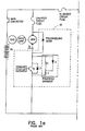
- the control system of this invention is shown in Figure 2 and consists of motor armature 1 together with its associated chopper control circuit 3 and field coil 2 together with its associated H-bridge control circuit 4.
- armature 1 and field coil 2 armature 1, with its control 3 and field coil 2, with its control 4 are each connected directly to DC supply 8 in a parallel relation as shown in Figures 1a and 1b as well as Figure 2 .
- the armature 1 is independently excited by a chopper circuit 3 which provides a pulsed voltage to armature 1.
- the current through the armature is varied by modulating the pulse width of the chopper output.
- a typical circuit for the chopper 3 is shown at 18 of Figure 1a .
- a mechanical throttle such as a foot pedal 9, shown in Figure 2 , may be employed to provide a signal to vary the chopper output.
- the current through the field coil 2 is supplied through H bridge circuit 4.
- a typical H bridge circuit is shown at 16 of Figure 1b .
- the field current is used as the main variable in the control circuit of this invention and is monitored by a current sensor 7.
- An armature current monitor 6 is connected in the armature circuit to sense the current flowing in the armature and generate a signal which is used as an indicator of the performance needs of the motor in the operation of the golf car.
- a voltage sensor 10 is provided to sense the armature voltage.
- a controller 5 is used to adjust the field current in response to performance conditions indicated by the armature current monitor signal.
- a speed sensor 11 is used to obtain signals indicative of the actual speed of the vehicle.
- This sensor 11 may be a simple Hall Effect device operatively associated with the armature shaft of the motor. Since this is the shaft which drives the wheels of the golf car, the speed sensor 11 will accurately reflect the actual speed of the car.
- the addition of the speed sensor 11 will simplify the detection of certain events, for example the starting or stopping of the car, overspeed, unintended movement, and stalling. With the speed sensor 11, armature current need not be monitored while the vehicle is stopped nor is a residual field necessary as in the prior system. The speed sensor 11 will provide a more precise regulation of vehicle top speed.
- the controller 5 is a microprocessor which is constructed to provide the well known and typical functions of receiving data, storing data, comparing data, and signal generation. Controller 5 compares the actual armature current and speed to predetermined data and generates a signal to adjust the field current according to the performance requirements of the golf car. The actual field current is monitored by field current monitor 7 which generates a signal to allow the controller 5 to determine when the current in field coil 2 is at the desired level. Controller 5 continuously compares the actual field current to the desired field current level generated at specific values of armature current.
- the typical motor used to propel a vehicle such as a golf car has an armature 1 which is mounted for rotation through a magnetic field set up by a field coil 2.
- the armature 1 and field coil 2, with their associated control circuits 3 and 4 respectively, are connected in parallel to a common DC voltage source such as a battery 8.
- a solenoid 13 controls the current to the armature control circuit 3 and can be actuated by the controller 5 when keyed switch 15 indicates the need to turn on the motor.
- the armature 1 and field coil 2 are independently excited.
- the motor is controlled through adjustment of the output of chopper circuit 3 by a throttle 9, such as a foot pedal.
- a sensor is provided on the foot pedal which generates a signal, the amplitude of which is proportional to the distance the pedal is depressed.
- a separate micro switch indicates when the throttle is engaged or released. Forward or Reverse modes of operation may be selected by a direction lever 12, the position of which is indicated by micro switches operatively associated with the lever 12. These indications are fed to the controller 5 to provide data relating to the sensed positions of the throttle 9 and lever 12.
- H bridge circuit 4 is particularly well adapted to enhance the effects of braking through adjustment of the field in the proper direction to increase the back emf.
- Circuit 4 can also accomplish field current reversal in opposition to armature rotation to provide dynamic braking. In the instance of regenerative braking, a current may be generated which is fed back to the battery through path 14. During dynamic braking, a majority of the current generated is dissipated in the armature.
- armature current is directly effected by the generation of the back emf, armature current provides a convenient indicator of some particular conditions which, without control adjustment, could result in undesirable performance.
- a performance map can be developed which relates particular performance events to appropriate responses.
- a performance map is extrapolated which relates actual data to desired performance and needed adjustment.
- two basic maps are provided, a map relating to stopping and starting, and a map relating to movement of the vehicle on grades.
- Each map consists of individual performance events or conditions, the actual parameter value or values that indicate the occurrence of an event or the presence of a condition, and a desired field current or in some instances armature voltage which enhances performance of the event. These maps are stored in controller 5 for reference when the sensors indicate the presence of a predetermined condition. Controller 5 can then compare actual field current to the desired field current from the map and adjust the field current accordingly.
- the controller 5 is supplied with data relative to a condition of speed decay caused by the golf car proceeding up a hill or other inclined surface. At this time more torque is needed and the speed tends to decline.
- the normal operating range of armature current used in a golf car type vehicle is approximately 0 to 300 amperes depending on a wide variety of factors. On level ground it is anticipated that the motor used in this particular application will draw approximately 35 amps while proceeding at a reasonable speed. As the golf car begins to climb a hill, the armature current may jump to 150 amps or more depending on the grade.
- an adjustment signal is generated to cause a change in the field current which will increase the torque available.
- armature current levels may be designed into the controller 5 which correspond to the armature current expected at a specific grade.
- a signal is generated proportional to the desired field current.
- the field current is then adjusted to provide increasing torque at a consistent speed. In this manner the uphill performance of the golf car is greatly improved.
- a performance curve P is illustrated in Figure 4 . These data will vary according to the characteristic curves T of the electric motor used. As shown in curve P of Figure 4 , the field current can be varied between approximately 0 to 20 amps. As shown, under normal conditions, the field current is held at approximately 4 amps and then increased or decreased, as required, when a predetermined current level is reached.
- the speed sensor signal is used and compared to a specific speed limit for the application.
- a speed of between 13 or 14 miles per hour is a reasonable limit and this can be set in a performance map for reference by the controller 5.
- Controller 5 will generate a responsive change in field current, if overspeed occurs.
- the field current adjustment in response to overspeed will be to enhance the effect of regenerative braking, namely by increasing the field current.
- a zero speed signal indicates a stopped condition.
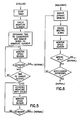
- the controller 5 upon the receipt of a zero speed signal, the controller 5 initiates a timed interval of about 2 seconds. If, after the interval has expired, the throttle is not depressed, a stopped condition is indicated. The controller 5 is provided with such data and responds by deactivating the motor. Deactivation is accomplished by reducing the duty cycle of control circuits 3 and 4 to zero and opening solenoid 13. Thereafter the controller 5 continues to monitor signals from the speed sensor to insure movement does not occur. In the event that movement begins, as indicated by the speed sensor, dynamic braking is applied. This event is referred to as walkaway in figure 6 .
- the speed sensor generates a signal proportional to the actual speed of the golf car while the field current monitor will generate a signal relative to the direction of movement.
- These speed signals are received by the controller 5, as shown in figure 2 , and provide a basic indication of whether the vehicle is moving and in which direction, forward or reverse.
- the speed signals allow the controller 5 to determine if the vehicle is moving opposite to the direction indicated by the position of the transmission lever 12. This indication will match a roll back condition on a hill identified in the performance map which is supplied to the controller 5. In this case a field current would be generated to oppose the movement and employ dynamic braking. If the speed signal is consistent with the movement desired by the user, the performance map will be searched for speed limit data to determine if an over speed condition is present. When over speed is indicated, regenerative braking will be initiated.
- an indicator of speed also provides critical data during a stalled condition.
- a zero speed signal in association with a depressed throttle will indicate a condition which may generate excessive armature current through a single point on the commutator. Such a situation could result while using the motor to hold position on a hill or while the car is impeded by an obstacle. If the condition is allowed to continue for an extended period, damage to the motor commutator could result.
- a time limit is provided, after which the armature control circuit duty cycle will be reduced as needed to avoid damage. This may be accomplished in steps with a reduction in armature duty cycle occurring at an interim points.
- the flow diagram of figure 5 illustrates the information processing of the performance map of the stalled condition.
- the time limit is contained in a look-up table stored in controller 5 which relates time, armature current and current limits.
- Dynamic braking involves the reversal of the field current to oppose the movement of the vehicle.
- the energy generated in dynamic braking is generally dissipated as heat in a resistive load.
- dynamic braking is used and dissipated through the armature as the load. This type of braking is called "plug" braking.
- plug braking
- This option is made available when the throttle pedal 9 is released indicating a desire to stop, thereby creating another event and response for the performance map referred to as a walkaway. The information processing of this condition is shown in figure 3 .
- Dynamic braking is also the response to a rollback event.
- the performance map of a preferred embodiment of this invention is comprised of several basic speed indications, events and responses as described above. These may be selectively grouped for selection where the terrain has consistent characteristics for example flat ground, hills, severe grades or all terrain. Through the use of appropriate means, for example, switches or plug in data cards, the controller 5 is instructed to use the map which accommodates the particular terrain. For example, a flat ground map may be designed with a higher speed for the overspeed condition or dynamic braking may be limited.
Description
- Electric motor driven vehicles, in particular golf cars, have many unique performance requirements that pose difficult obstacles to the design of control systems for direct current motors used as the primary means of propulsion.
- Drive systems of the prior art employ shunt type motors, which have their armature and field windings connected in parallel to a common source of voltage. By adapting the input power to the motor to provide independent excitation of the armature and field windings further flexibility can be achieved. It is the purpose of a preferred embodiment of this invention to control an independently excited shunt motor in accordance with a predetermined field current map to provide enhanced performance in the propulsion of a golf car.
- Shunt motors tend to have a characteristic response curve, namely a specific speed for a specific load. This is a result of a balancing of the input voltage and the back emf generated by the motion of the motor armature through the magnetic field established by the energized field coil. Speed and torque can be conveniently controlled by the adjustment of the voltage or current across or in either the armature or the field winding or both. Although motor control can be obtained through either the armature current or the field current, it is advantageous to rely on the variation of field current because of the lower current levels. The use of field current enables the use of low power, less expensive components that increase efficiency. It is the purpose of a preferred embodiment of this invention to provide a system of control which allows operation of the motor along its full range of response characteristics in accordance with a particular armature current to field current map.
- Basic speed control for such motors involves the use of a chopper circuit to supply pulses of voltage to the armature which are varied in duty cycle from 0 to 100% according to the desired speed in response to the manually operated throttle. Further refinement of the control is provided by an H bridge circuit operatively connected to vary the current in the field winding. These circuits are well known in the art.
- The more sophisticated motor control circuits are now based on the operation of discrete logic or microprocessors and can function to provide a variable torque at near constant speed. An example of one such system particularly adapted to the control of electric vehicles driven by a separately excited shunt wound motor is described in
U.S. Patent No. 5,264,763 . In the system of the '763 patent, the armature winding is controlled by modulating the pulse width of the voltage output of a chopper exciter circuit 17 while the field current is controlled by theH bridge circuit 16. The system of the '763 patent adjusts the armature and field voltage in response to the speed of the driven wheel. It is an object of a preferred embodiment of this invention to realize the full potential of this type of control circuit to enhance the performance of the drive system for a golf car or other vehicle through the adjustment of the field current. - A great deal of design effort has been exerted to utilize the power generation characteristic of an electric motor to provide a braking action in a motor used for driving a vehicle. This can be accomplished in many ways for example by reversing the voltage on the field or armature winding, by raising field current to increase the back emf, or by providing a return path for current through the armature upon disconnecting the input power to the armature. It is a purpose of a preferred embodiment of this invention to use this characteristic to enhance the performance of a golf car in its normal use.
- The operation of a golf car is unique because of the uneven terrain which is continuously traversed and the continuous need for stopping and parking the car. Although a very simple control circuit can provide constant speed propulsion along a flat path, most courses are designed to challenge the golfer. Hills, valleys, bunkers, ditches and the like, all of which need to be navigated by the golf car are a standard part of any course. It is a purpose of a preferred embodiment of this invention to provide a selection of performance characteristics for common types of terrain.
- In using electric motor powered golf cars, there is a continuous need for the driver to be alert to an over speed condition on down hill runs and to apply the mechanical braking system to slow down the vehicle. In gas powered golf cars the compression of the engine cylinders provides some restraining force against over speed when the car is proceeding downhill. The electric motor has no similar restraint unless the regenerative nature of the armature can be actuated to provide auxiliary braking.
- It is a purpose of a preferred embodiment of this invention to provide an efficient mechanism for utilizing both regenerative braking and dynamic braking depending on the performance circumstances. Regenerative braking involves the use of the back emf generated in the armature to retard rotation of the armature and therefore the speed of the golf car. Dynamic braking is accomplished by reversing the field current and dissipating the resultant energy generated as the armature rotation slows to a stop.
- As in any vehicle many functions of a golf car depend on the actions of the driver. When a golf car is stopped it should be stopped on level ground and the mechanical brake must be reliably set. If the driver is negligent the car could continue to roll even though the motor is turned off. The irresponsible or forgetful driver could use a mechanism which would sense movement after the car is brought to rest. It is a purpose of a preferred embodiment of this invention to sense actual speed at the axle and provide a control system having an additional operation alert function which will sense the movement of a car after it comes to rest and initiate dynamic braking in the proper direction to limit the speed of the vehicle.
- The driver of a golf car also faces the opposite of the over speed event when operating the vehicle on an upward incline. In this situation the car will tend to slow down as the load on the motor increases. This will occur as the golf car proceeds up the grade, placing the driver at the mercy of the characteristic torque versus speed curve of the motor. It is a purpose of a preferred embodiment of this invention to provide a control circuit which can adjust the operational performance of the motor to obtain a full range of available torque while maintaining sufficient speed.
- It is the purpose of a preferred embodiment of this invention to provide system of performance maps which provide predetermined field current responses. These performance maps may be grouped according to the local terrain for selection by the user.
- Particular Aspects of the invention are set out in the independent claims. A system is provided in one example for controlling a D-C motor which is constructed to propel a golf car. The motor is controlled to provide performance according to a predetermined field current map which calls for a particular performance response to specified performance events. The performance events are detected by sensing actual speed and armature current and the performance response is triggered by adjustment of the field current or other appropriate parameters. A performance map correlating actual speed to various events and specifying the field current response is designed for the motor used. In addition an armature current performance map is similarly constructed correlating armature current to particular performance events. A selection of performance maps are provided which are designed for specific types of terrain, for example, level ground, all-terrain, small to medium grades, and steep grades.
- Preferably, the motor is a shunt wound motor having independently excited armature and field windings. The basic input to the armature of the motor is supplied through a pulse width modulated chopper circuit which varies the width of its output voltage pulse (duty cycle) in response to the throttle of the golf car. Full control of the input to the field winding is gained by the supply of power to an H bridge circuit. Armature current is continuously sensed to provide an indication of the status and performance of the car during operation. In addition actual speed of the golf car is sensed. At a predetermined level of armature current indicative of going up a hill, the field current is adjusted to provide a higher torque at a specific speed. If sensed speed indicates a predetermined over speed condition, as for example when the vehicle coasts, field current is increased to enhance regeneration and the resultant braking. After the speed sensor indicates that the vehicle has stopped, a predetermined delay is initiated and if the speed sensor indicates thereafter, that the vehicle has begun to roll, an appropriate field current can be applied to limit the speed of the car. The at rest condition is continuously monitored by the speed sensor, if movement of the car begins, the direction can be established and the circuitry will apply a current to the field winding to initiate dynamic braking.
- The preferred embodiment of this invention is described in more detail below with reference to the Drawing in which:
-
Figures 1a and1b are circuit diagrams showing a control circuit of the prior art; -
Figure 2 is a schematic diagram depicting the flow of information among the components of the invention; -
Figure 3 is a flow diagram for the operation of this invention for controlling the speed and torque characteristics of the motor during movement and when the throttle is released; -
Figure 4 is a chart showing torque curves and a performance profile for the motor controlled by the system of this invention; -
Figure 5 is a flow diagram for the operation of this invention for controlling the motor during the stalled condition; and -
Figure 6 is a flow diagram for the operation of this invention for controlling the motor during the stopped condition; - This invention is described in relation to a golf car but is applicable to any vehicle which utilizes a direct current electric motor to drive its wheels. The motor which is used consists of a shunt type with independently excited armature and field windings such as an Advanced D.C. Motors model no. AY6-4002. A typical control circuit is shown and described in
U.S. Patent No. 5,264,763 which is incorporated herein by reference. - The control system of this invention is shown in
Figure 2 and consists ofmotor armature 1 together with its associated chopper control circuit 3 andfield coil 2 together with its associated H-bridge control circuit 4. In order to provide independently controlled inputs toarmature 1 andfield coil 2,armature 1, with its control 3 andfield coil 2, with itscontrol 4 are each connected directly toDC supply 8 in a parallel relation as shown inFigures 1a and1b as well asFigure 2 . - The
armature 1 is independently excited by a chopper circuit 3 which provides a pulsed voltage toarmature 1. The current through the armature is varied by modulating the pulse width of the chopper output. A typical circuit for the chopper 3 is shown at 18 ofFigure 1a . A mechanical throttle such as afoot pedal 9, shown inFigure 2 , may be employed to provide a signal to vary the chopper output. - The current through the
field coil 2 is supplied throughH bridge circuit 4. A typical H bridge circuit is shown at 16 ofFigure 1b . The field current is used as the main variable in the control circuit of this invention and is monitored by acurrent sensor 7. - An armature
current monitor 6 is connected in the armature circuit to sense the current flowing in the armature and generate a signal which is used as an indicator of the performance needs of the motor in the operation of the golf car. For additional control in certain instances, avoltage sensor 10 is provided to sense the armature voltage. A controller 5 is used to adjust the field current in response to performance conditions indicated by the armature current monitor signal. - As a further means to monitor the operation of the motor, a
speed sensor 11 is used to obtain signals indicative of the actual speed of the vehicle. Thissensor 11 may be a simple Hall Effect device operatively associated with the armature shaft of the motor. Since this is the shaft which drives the wheels of the golf car, thespeed sensor 11 will accurately reflect the actual speed of the car. The addition of thespeed sensor 11 will simplify the detection of certain events, for example the starting or stopping of the car, overspeed, unintended movement, and stalling. With thespeed sensor 11, armature current need not be monitored while the vehicle is stopped nor is a residual field necessary as in the prior system. Thespeed sensor 11 will provide a more precise regulation of vehicle top speed. - The controller 5 is a microprocessor which is constructed to provide the well known and typical functions of receiving data, storing data, comparing data, and signal generation. Controller 5 compares the actual armature current and speed to predetermined data and generates a signal to adjust the field current according to the performance requirements of the golf car. The actual field current is monitored by field
current monitor 7 which generates a signal to allow the controller 5 to determine when the current infield coil 2 is at the desired level. Controller 5 continuously compares the actual field current to the desired field current level generated at specific values of armature current. - Referring to
Figure 2 , the typical motor used to propel a vehicle such as a golf car has anarmature 1 which is mounted for rotation through a magnetic field set up by afield coil 2. Thearmature 1 andfield coil 2, with their associatedcontrol circuits 3 and 4 respectively, are connected in parallel to a common DC voltage source such as abattery 8. Asolenoid 13 controls the current to the armature control circuit 3 and can be actuated by the controller 5 when keyedswitch 15 indicates the need to turn on the motor. - As indicated above, the
armature 1 andfield coil 2 are independently excited. Under normal operating conditions, the motor is controlled through adjustment of the output of chopper circuit 3 by athrottle 9, such as a foot pedal. A sensor is provided on the foot pedal which generates a signal, the amplitude of which is proportional to the distance the pedal is depressed. In addition a separate micro switch indicates when the throttle is engaged or released. Forward or Reverse modes of operation may be selected by adirection lever 12, the position of which is indicated by micro switches operatively associated with thelever 12. These indications are fed to the controller 5 to provide data relating to the sensed positions of thethrottle 9 andlever 12. - As the
armature 1 moves through the magnetic field of thefield coil 2, it will act as a generator and a counter or back emf will be generated in opposite polarity to the supply voltage. This characteristic tends to limit the torque available at a given field current. Typical torque curves T of a shunt motor appropriate for use as the driver of a golf car are shown infigure 4 . By varying the field current, increased torque becomes available and a performance profile P is obtained. This is advantageous because compromises must otherwise be made to provide the required torque at a reasonable speed throughout the operating profile of the golf car. - The back emf also tends to retard the rotation of the armature and this characteristic, generally referred to as regenerative braking provides a mechanism to slow the car.
H bridge circuit 4 is particularly well adapted to enhance the effects of braking through adjustment of the field in the proper direction to increase the back emf.Circuit 4 can also accomplish field current reversal in opposition to armature rotation to provide dynamic braking. In the instance of regenerative braking, a current may be generated which is fed back to the battery throughpath 14. During dynamic braking, a majority of the current generated is dissipated in the armature. - Since armature current is directly effected by the generation of the back emf, armature current provides a convenient indicator of some particular conditions which, without control adjustment, could result in undesirable performance.
- Through the investigation of the performance profile of a particular motor, data indicative of certain performance events can be developed. By comparing the performance event data with actual data, an optimum response profile consistent with a particular application is compiled. In this manner a performance map can be developed which relates particular performance events to appropriate responses. By an analysis of the information sensed in the system, such as speed and direction, armature current and voltage, and other parameters, a performance map is extrapolated which relates actual data to desired performance and needed adjustment. In the system of this invention two basic maps are provided, a map relating to stopping and starting, and a map relating to movement of the vehicle on grades.
- Each map consists of individual performance events or conditions, the actual parameter value or values that indicate the occurrence of an event or the presence of a condition, and a desired field current or in some instances armature voltage which enhances performance of the event. These maps are stored in controller 5 for reference when the sensors indicate the presence of a predetermined condition. Controller 5 can then compare actual field current to the desired field current from the map and adjust the field current accordingly.
- In the normal operation of a preferred embodiment of this invention as illustrated in
figure 3 , the controller 5 is supplied with data relative to a condition of speed decay caused by the golf car proceeding up a hill or other inclined surface. At this time more torque is needed and the speed tends to decline. The normal operating range of armature current used in a golf car type vehicle is approximately 0 to 300 amperes depending on a wide variety of factors. On level ground it is anticipated that the motor used in this particular application will draw approximately 35 amps while proceeding at a reasonable speed. As the golf car begins to climb a hill, the armature current may jump to 150 amps or more depending on the grade. In the present system when the actual armature current reaches a preset data point such as 150 amps, an adjustment signal is generated to cause a change in the field current which will increase the torque available. Several armature current levels may be designed into the controller 5 which correspond to the armature current expected at a specific grade. In the preferred embodiment, at a predetermined armature current level, a signal is generated proportional to the desired field current. The field current is then adjusted to provide increasing torque at a consistent speed. In this manner the uphill performance of the golf car is greatly improved. A performance curve P is illustrated inFigure 4 . These data will vary according to the characteristic curves T of the electric motor used. As shown in curve P ofFigure 4 , the field current can be varied between approximately 0 to 20 amps. As shown, under normal conditions, the field current is held at approximately 4 amps and then increased or decreased, as required, when a predetermined current level is reached. - Once the hill is climbed and the golf car proceeds over the crest, a new performance requirement occurs. The torque load on the motor begins to decrease as gravity begins to assist the progress of the car, resulting in an acceleration of the vehicle speed. This is an undesirable effect and the operator of the golf car is called upon to release the
throttle 9 and use the mechanical braking system. During this mode of operation the back emf of thearmature 1 begins to increase and the armature current will drop because the motion of the vehicle is now driving thearmature 1 as opposed to the reverse in normal operation. A level of, for example 0 amps armature current at full operating voltage would indicate an over speed condition. Reliance on armature current as an indicator of over speed, however, may be cumbersome. - In the system of a preferred embodiment of this invention the speed sensor signal is used and compared to a specific speed limit for the application. In the golf car, a speed of between 13 or 14 miles per hour is a reasonable limit and this can be set in a performance map for reference by the controller 5. Controller 5 will generate a responsive change in field current, if overspeed occurs. The field current adjustment in response to overspeed will be to enhance the effect of regenerative braking, namely by increasing the field current.
- In this manner, a map of performance events is developed based upon the performance on hilly terrain. By anticipating what field current is needed at a particular event, the performance may be immediately enhanced as the need arises.
- One of the dominant modes of operation of a golf car is the need to frequently stop the car and park. This can create problems depending on the nature of the ground where the car is parked. Mechanical brakes are dependent on the driver to operate and need to be set. A forgetful or negligent driver could face the situation that the car continues to roll after it is parked. In this case a zero speed signal indicates a stopped condition. As shown in
figure 3 , upon the receipt of a zero speed signal, the controller 5 initiates a timed interval of about 2 seconds. If, after the interval has expired, the throttle is not depressed, a stopped condition is indicated. The controller 5 is provided with such data and responds by deactivating the motor. Deactivation is accomplished by reducing the duty cycle ofcontrol circuits 3 and 4 to zero and openingsolenoid 13. Thereafter the controller 5 continues to monitor signals from the speed sensor to insure movement does not occur. In the event that movement begins, as indicated by the speed sensor, dynamic braking is applied. This event is referred to as walkaway infigure 6 . - The speed sensor generates a signal proportional to the actual speed of the golf car while the field current monitor will generate a signal relative to the direction of movement. These speed signals are received by the controller 5, as shown in
figure 2 , and provide a basic indication of whether the vehicle is moving and in which direction, forward or reverse. As shown infigure 3 , the speed signals allow the controller 5 to determine if the vehicle is moving opposite to the direction indicated by the position of thetransmission lever 12. This indication will match a roll back condition on a hill identified in the performance map which is supplied to the controller 5. In this case a field current would be generated to oppose the movement and employ dynamic braking. If the speed signal is consistent with the movement desired by the user, the performance map will be searched for speed limit data to determine if an over speed condition is present. When over speed is indicated, regenerative braking will be initiated. - The use of an indicator of speed also provides critical data during a stalled condition. A zero speed signal in association with a depressed throttle will indicate a condition which may generate excessive armature current through a single point on the commutator. Such a situation could result while using the motor to hold position on a hill or while the car is impeded by an obstacle. If the condition is allowed to continue for an extended period, damage to the motor commutator could result. In the performance map, a time limit is provided, after which the armature control circuit duty cycle will be reduced as needed to avoid damage. This may be accomplished in steps with a reduction in armature duty cycle occurring at an interim points. The flow diagram of
figure 5 illustrates the information processing of the performance map of the stalled condition. The time limit is contained in a look-up table stored in controller 5 which relates time, armature current and current limits. - Under certain conditions, dynamic braking is provided. Dynamic braking involves the reversal of the field current to oppose the movement of the vehicle. The energy generated in dynamic braking is generally dissipated as heat in a resistive load. In the system of a preferred embodiment of this invention dynamic braking is used and dissipated through the armature as the load. This type of braking is called "plug" braking. This option is made available when the
throttle pedal 9 is released indicating a desire to stop, thereby creating another event and response for the performance map referred to as a walkaway. The information processing of this condition is shown infigure 3 . Dynamic braking is also the response to a rollback event. - The performance map of a preferred embodiment of this invention is comprised of several basic speed indications, events and responses as described above. These may be selectively grouped for selection where the terrain has consistent characteristics for example flat ground, hills, severe grades or all terrain. Through the use of appropriate means, for example, switches or plug in data cards, the controller 5 is instructed to use the map which accommodates the particular terrain. For example, a flat ground map may be designed with a higher speed for the overspeed condition or dynamic braking may be limited.
- In this manner speed is used as an effective control parameter and a simplified mechanism for providing an enhanced performance profile.
- In view of the foregoing description it will be evident to a person skilled in the art that various modifications may be made within the scope of the invention as defined in the claims.
Claims (13)
- A method of controlling an electric DC motor used to propel a golf car under the control of an operator to obtain a desired performance profile, said motor having armature (1) and field coils (2) which are independently excited by a source of voltage (8) to generate armature and field currents, said motor having a characteristic performance profile having predetermined armature current levels indicative of a specific operational event, predetermined speed values indicative of a specific operational event, and predetermined field current levels which will enhance performance of the motor in response to a specific operational event to obtain the desired performance profile wherein the specific operational event is selected from the group comprising:stopping and starting of the golf car; and movement of the golf car on gradients, the method comprising the steps of:(i) sensing the armature current of the motor and generating a signal relative thereto;(ii) sensing the field current of the motor and generating a signal relative thereto;(iii) sensing the speed of the golf car and generating a signal relative thereto using a speed monitor connected to sense the movement of the golf car;(iv) comparing said armature current signal to said predetermined armature current level to identify the occurrence of said operational event;(v) comparing said speed signal to said predetermined speed value to identify the occurrence of said operational event;(vi) generating a field current adjustment signal for the specific operational event in accordance with said predetermined field current levels, when said armature current signal indicates an operational event has occurred; and(vii) comparing the field current signal with the field current adjustment signal and adjusting the field current to obtain the predetermined field current.
- The method of claim 1 comprising the further steps of:setting a predetermined speed value at zero;sensing a condition when an operator provides an input to reduce the speed of the golf car to zero;initiating a timed interval when the sensed speed is zero; andgenerating a field current adjustment signal, upon the expiration of said timed interval, if the sensed speed is other than zero, said adjustment signal causing the field current to be applied to initiate dynamic braking.
- The method of claim 1 comprising the further steps of:setting a predetermined speed value at zero;sensing a condition when an operator provides an input to reduce the speed of the golf car to zero;initiating a timed interval when the sensed speed is zero; andgenerating an adjustment signal, upon the expiration of said timed interval, if the sensed speed is zero, said adjustment signal causing the source of voltage to the armature to be reduced to zero.
- The method of claim 1 comprising the further steps of:setting a predetermined speed value at substantially zero;sensing a condition when an operator provides an input to cause the motor to move the golf car;initiating a timed interval when the sensed speed is zero; andgenerating an adjustment signal upon the expiration of said timed interval if the sensed speed is still zero, said adjustment signal reducing the source of voltage to the armature thereby preventing damage to the motor.
- The method of claim 1 comprising the further steps of:sensing a condition when the motor is propelling the golf car;setting a predetermined speed of the golf car at a specific maximum speed; andgenerating a field current adjustment signal when the sensed speed is in excess of said predetermined maximum value, said adjustment signal causing an increase in the field current to enhance regenerative braking.
- The method of claim 1 further comprising the steps of:selecting a plurality of said predetermined armature current levels, speed values and field current levels into predetermined groups in accordance with a desired performance profile for a characteristic terrain; andselecting a class in accordance with the actual terrain.
- Apparatus for controlling the performance of a DC motor used for driving a golf can comprising:a source of d. c. voltage (8);a motor armature (1) connected to the voltage source through an armature control circuit to provide independent control of the armature;a motor field winding (2) magnetically coupled to the motor armature in operative relation and connected directly to the source of voltage through a field winding control circuit to provide control of the field winding independent of the armature;an armature current monitor (3) connected to sense the current in the armature and to generate a signal relative thereto;a field current monitor (4) connected to sense the current in the field winding and to generate a signal relative thereto;a speed monitor (11) connected to sense the movement of the golf car and to generate a signal relative thereto;a controller (5) connected to receive signals from the armature current, field current and speed monitors and further comprising:means configured to receive predetermined armature current values indicative of a specific performance condition selected from the group comprising: stopping and starting of the golf car; and movement of the golf car on gradients;means configured to receive predetermined speed values indicative a specific performance condition selected from the group comprising: stopping and starting of the golf car; and movement of the golf car on gradients;means configured to receive predetermined field current values indicative of the desired performance response to said performance condition;means configured to compare said armature current signals with said predetermined armature current value to identify the occurrence of said performance condition;means configured to compare said speed signal to said predetermined speed value to identify the occurrence of said performance condition;means configured to compare said field current monitor signal with said predetermined field current value for the desired response to said identified performance condition and to generate a field current adjustment signal; andwherein the field winding control circuit is configured to adjust the field current in response to the field current adjustment signal.
- Apparatus according to claim 7 further comprising means operable to sense the motor being denergized and wherein:a predetermined speed value is set at zero; andthe controller (5) is configured to initiate a timed interval in response to the signal of the speed monitor indicating a speed of zero, and to generate a signal to cause the field current winding control circuit to reverse the direction of the field current and cause dynamic braking upon the expiration of said interval, if the signal of the speed monitor indicates a speed of other than zero.
- Apparatus according to claim 7 wherein:a predetermined speed value is set at zero; andthe controller (5) is configured to initiate a timed interval in response to the signal of the speed monitor indicating a speed of zero, and to generate a signal to cause the armature control circuit to reduce the voltage to the armature to zero upon the expiration of said interval, if the speed value signal of the speed monitor still indicates a speed of zero.
- Apparatus according to claim 7 further comprising means operable to sense a condition when the motor is energized to cause movement of the golf car, and further wherein:a predetermined speed value is set at zero; andthe controller (5) is configured to initiate a timed interval in response to the signal of the speed monitor indicating a speed of zero, and to generate a signal to cause the armature control circuit to reduce the voltage to the armature and thereby prevent damage to the motor upon the expiration of said timed interval, if the signal of the speed monitor still indicates a speed of zero.
- Apparatus according to claim 7 further comprising means operable to sense a condition when the golf car is moving and further wherein:a predetermined speed value is set at a predetermined maximum value; andthe controlleer (5) is configured to generate a field current adjustment signal to cause an increase in the field current to enhance regenerative braking in response to the signal of the speed monitor indicating a speed in excess of said predetermined maximum value.
- Apparatus according to claim 7 further comprising:means configured to sense a condition when the motor is energized to cause movement of the golf car in a particular direction; andmeans configured to sense the actual direction of movement of the golf car; andfurther wherein the controller (5) is configured, to generate a signal to cause the filed winding control circuit to reverse the direction of the field current to cause dynamic braking in opposition to the actual movement in response to the actual direction of movement being opposed to the energized direction.
- Apparatus according to claim 7 wherein the controller further comprises:means configured to receive a plurality of said predetermined armature current values, speed values, and field current values grouped in accordance with the desired performance profile for a characteristic terrain; andmeans configured to select a group in accordance with the actual terrain.
Applications Claiming Priority (2)
| Application Number | Priority Date | Filing Date | Title |
|---|---|---|---|
| US08/843,010 US5793175A (en) | 1995-01-19 | 1997-04-11 | Performance event sensing for control of electric motor driven golf car |
| US843010 | 1997-04-11 |
Publications (3)
| Publication Number | Publication Date |
|---|---|
| EP0870641A2 EP0870641A2 (en) | 1998-10-14 |
| EP0870641A3 EP0870641A3 (en) | 1999-03-17 |
| EP0870641B1 true EP0870641B1 (en) | 2010-08-11 |
Family
ID=25288823
Family Applications (1)
| Application Number | Title | Priority Date | Filing Date |
|---|---|---|---|
| EP98302817A Expired - Lifetime EP0870641B1 (en) | 1997-04-11 | 1998-04-09 | Performance event sensing for control of electric motor driven golf car |
Country Status (5)
| Country | Link |
|---|---|
| US (1) | US5793175A (en) |
| EP (1) | EP0870641B1 (en) |
| JP (1) | JPH10309005A (en) |
| CA (1) | CA2233866C (en) |
| DE (1) | DE69841817D1 (en) |
Families Citing this family (22)
| Publication number | Priority date | Publication date | Assignee | Title |
|---|---|---|---|---|
| US6031965A (en) * | 1997-07-08 | 2000-02-29 | Solaria Research Enterprise, Ltd. | Separately excited DC motor with boost and de-boost control |
| US6021251A (en) * | 1997-07-08 | 2000-02-01 | Crown Equipment Corporation | Compensated field current control for a separately excited DC motor |
| US6288508B1 (en) * | 1997-11-05 | 2001-09-11 | Yamaha Hatsudoki Kabushiki Kaisha | Electric motor for a vehicle having regenerative braking and reverse excitation braking |
| JP4093515B2 (en) * | 1999-05-12 | 2008-06-04 | 本田技研工業株式会社 | Front and rear wheel drive vehicle |
| US6462506B2 (en) | 1999-12-30 | 2002-10-08 | Textron Inc. | Electric golf car with low-speed regenerative braking |
| US6293077B1 (en) | 2000-05-02 | 2001-09-25 | Mtd Products Inc | Deck attachment and lift system |
| US6373207B1 (en) | 2000-07-11 | 2002-04-16 | Kalish Inc. | Braking system for a DC motor |
| US20030042859A1 (en) * | 2001-08-06 | 2003-03-06 | Gorti Bhanuprasad V. | Excitation circuit and control method for flux switching motor |
| US6943510B2 (en) * | 2001-08-06 | 2005-09-13 | Black & Decker Inc. | Excitation circuit and control method for flux switching motor |
| JP2005312109A (en) * | 2004-04-19 | 2005-11-04 | Moric Co Ltd | Regenerative brake system of electric vehicle |
| JP2005333729A (en) * | 2004-05-20 | 2005-12-02 | Moric Co Ltd | Drive controller for electric vehicle |
| JP2006025470A (en) | 2004-07-06 | 2006-01-26 | Moric Co Ltd | Drive controller of electric vehicle |
| CN101209682B (en) * | 2006-12-26 | 2010-09-29 | 比亚迪股份有限公司 | Electric motor outputting torque moment control system and control method in electric automobile ascending condition |
| CN101209681B (en) * | 2006-12-26 | 2010-09-29 | 比亚迪股份有限公司 | Electric motor outputting torque moment control system and control method in electric automobile descending condition |
| US7926889B2 (en) * | 2007-10-29 | 2011-04-19 | Textron Innovations Inc. | Hill hold for an electric vehicle |
| US8169335B2 (en) | 2008-03-24 | 2012-05-01 | Strata Proximity Systems, Llc | Electromagnetic field adjustment for proximity detection |
| JP5067326B2 (en) * | 2008-09-16 | 2012-11-07 | 新神戸電機株式会社 | Driving control system for electromagnetic induction golf cart |
| NZ588233A (en) | 2010-09-28 | 2011-06-30 | Dynamic Controls | Dynamically adjusting a compensation term based on a stored profile for a motor |
| DE102011118488A1 (en) * | 2011-11-11 | 2013-05-16 | Maschinenfabrik Reinhausen Gmbh | Motor drive for tap changer |
| EP2969642A4 (en) | 2013-03-14 | 2016-11-16 | Boosted Inc | Dynamic control for light electric vehicles |
| US10486051B2 (en) | 2017-09-26 | 2019-11-26 | Boosted, Inc. | Backpack for a personal transport vehicle |
| US20200384976A1 (en) * | 2019-06-05 | 2020-12-10 | Avx Electronics Technology Limited | System for Sensing a Position of a First Member Relative to a Second Member Based on a Radio Frequency Characteristic of a Bias Member |
Family Cites Families (22)
| Publication number | Priority date | Publication date | Assignee | Title |
|---|---|---|---|---|
| US3194715A (en) * | 1961-11-21 | 1965-07-13 | Gambin Michel Philipp Francois | Apparatus for hot vulcanizing seams in rubberized elements |
| US3566227A (en) * | 1969-05-06 | 1971-02-23 | Minnesota Mining & Mfg | Switching circuit for operation and dynamic braking of a dc motor |
| US3597669A (en) * | 1970-04-30 | 1971-08-03 | Eaton Yale & Towne | Electrical braking system for electric motor-driven vehicles |
| US4090114A (en) * | 1974-03-07 | 1978-05-16 | Westinghouse Electric Corp. | Safety features for electric vehicle control |
| US4079301A (en) * | 1976-12-17 | 1978-03-14 | General Electric Company | D.C. motor control |
| DE2755246C2 (en) * | 1977-12-12 | 1982-06-03 | Siemens AG, 1000 Berlin und 8000 München | Circuit arrangement for braking a direct current series machine |
| JPS5594502A (en) * | 1979-01-12 | 1980-07-18 | Hitachi Ltd | Electromobile control device |
| US4385266A (en) * | 1980-03-18 | 1983-05-24 | Technical Operations Limited | Field weakening system for pulse-controlled three-terminal d.c. motor |
| JPS56148102A (en) * | 1980-04-16 | 1981-11-17 | Hitachi Ltd | Control equipment of electric rolling stock |
| JPS57166804A (en) * | 1981-04-01 | 1982-10-14 | Mitsubishi Electric Corp | Control device for electric motor vehicle |
| US4375603A (en) * | 1981-05-20 | 1983-03-01 | General Electric Company | Shunt-wound control for on-road vehicle |
| JPS59178902A (en) * | 1983-03-25 | 1984-10-11 | Mitsubishi Electric Corp | Controller for electric rolling stock |
| US4479080A (en) * | 1983-04-25 | 1984-10-23 | General Electric Company | Electrical braking control for DC motors |
| DE3541276A1 (en) * | 1985-11-22 | 1987-05-27 | Heidelberger Druckmasch Ag | CONTROL DEVICE FOR A FOREIGN REGULATED DC DRIVE MOTOR AND METHOD FOR CONTROLLING A DC DRIVE MOTOR OF A PRINTING MACHINE OR THE LIKE |
| US4816726A (en) * | 1987-09-14 | 1989-03-28 | United Technologies Corporation | Method of and arrangement for controlling and h-bridge electric motor |
| US5030898A (en) * | 1990-03-30 | 1991-07-09 | General Electric Company | Variable voltage limit control for an electric propulsion system |
| US5039924A (en) * | 1990-05-07 | 1991-08-13 | Raymond Corporation | Traction motor optimizing system for forklift vehicles |
| US5340202A (en) * | 1991-10-30 | 1994-08-23 | Raymond Corporation | Service braking technique for material handling vehicles |
| US5453672A (en) * | 1991-12-31 | 1995-09-26 | Avitan; Isaac | Regulation system for decoupled efficiency optimized operation of DC traction motors |
| US5264763A (en) * | 1992-10-29 | 1993-11-23 | Schaeff Inc. | Optimizing system for vehicle traction motors |
| US5565760A (en) * | 1994-11-02 | 1996-10-15 | General Electric Company | Electrical propulsion systems for a golf car |
| US5642023A (en) * | 1995-01-19 | 1997-06-24 | Textron Inc. | Method and apparatus for the electronic control of electric motor driven golf car |
-
1997
- 1997-04-11 US US08/843,010 patent/US5793175A/en not_active Expired - Lifetime
-
1998
- 1998-04-02 CA CA002233866A patent/CA2233866C/en not_active Expired - Lifetime
- 1998-04-09 EP EP98302817A patent/EP0870641B1/en not_active Expired - Lifetime
- 1998-04-09 DE DE69841817T patent/DE69841817D1/en not_active Expired - Lifetime
- 1998-04-13 JP JP10100805A patent/JPH10309005A/en active Pending
Also Published As
| Publication number | Publication date |
|---|---|
| US5793175A (en) | 1998-08-11 |
| CA2233866C (en) | 2003-10-07 |
| EP0870641A2 (en) | 1998-10-14 |
| CA2233866A1 (en) | 1998-10-11 |
| JPH10309005A (en) | 1998-11-17 |
| EP0870641A3 (en) | 1999-03-17 |
| DE69841817D1 (en) | 2010-09-23 |
Similar Documents
| Publication | Publication Date | Title |
|---|---|---|
| EP0870641B1 (en) | Performance event sensing for control of electric motor driven golf car | |
| US5814958A (en) | Method and apparatus for the electronic control of electric motor driven golf car | |
| US5343971A (en) | Electric vehicle with individually controlled drive electromotors | |
| US5764009A (en) | Motor control device in electric motor-operated vehicle | |
| EP0585122B1 (en) | Control device for electric vehicles | |
| CN102632799B (en) | Vehicle drive control device | |
| US7362065B2 (en) | Regenerative breaking system for electric vehicle | |
| EP0710582A1 (en) | Electrically propelled car | |
| US6288508B1 (en) | Electric motor for a vehicle having regenerative braking and reverse excitation braking | |
| JPH11113108A (en) | Electric vehicle | |
| JPH05236604A (en) | Low loss control method of electrically driven vehicle | |
| JPH07504078A (en) | Rotational speed detection in drives for motorized vehicles | |
| JP3362156B2 (en) | Vehicle voltage control device | |
| JP3596389B2 (en) | Battery-powered golf cart | |
| JP3802355B2 (en) | Electric vehicle speed control device | |
| CA1066391A (en) | Prime mover speed responsive load control for electrically propelled traction vehicles | |
| JP5012595B2 (en) | Driving control system for electromagnetic induction golf cart | |
| JP3295566B2 (en) | Automatic driving vehicle braking method | |
| JP3208461B2 (en) | Travel speed control device for autonomous vehicles | |
| JP4079085B2 (en) | VEHICLE CONTROL DEVICE AND VEHICLE CONTROL METHOD | |
| JP4439310B2 (en) | Hybrid vehicle | |
| JP3802356B2 (en) | Electric vehicle travel control device | |
| JP2003199202A (en) | Speed control device for automatic traveling vehicle | |
| JP2002262594A (en) | Control device for dc motor | |
| JP3205755B2 (en) | Power regeneration method of motor in battery power supply |
Legal Events
| Date | Code | Title | Description |
|---|---|---|---|
| PUAI | Public reference made under article 153(3) epc to a published international application that has entered the european phase |
Free format text: ORIGINAL CODE: 0009012 |
|
| AK | Designated contracting states |
Kind code of ref document: A2 Designated state(s): DE FR GB IT |
|
| AX | Request for extension of the european patent |
Free format text: AL;LT;LV;MK;RO;SI |
|
| PUAL | Search report despatched |
Free format text: ORIGINAL CODE: 0009013 |
|
| AK | Designated contracting states |
Kind code of ref document: A3 Designated state(s): AT BE CH CY DE DK ES FI FR GB GR IE IT LI LU MC NL PT SE |
|
| AX | Request for extension of the european patent |
Free format text: AL;LT;LV;MK;RO;SI |
|
| 17P | Request for examination filed |
Effective date: 19990621 |
|
| AKX | Designation fees paid |
Free format text: DE FR GB IT |
|
| 17Q | First examination report despatched |
Effective date: 20071024 |
|
| GRAP | Despatch of communication of intention to grant a patent |
Free format text: ORIGINAL CODE: EPIDOSNIGR1 |
|
| GRAS | Grant fee paid |
Free format text: ORIGINAL CODE: EPIDOSNIGR3 |
|
| GRAA | (expected) grant |
Free format text: ORIGINAL CODE: 0009210 |
|
| RAP1 | Party data changed (applicant data changed or rights of an application transferred) |
Owner name: TEXTRON INNOVATIONS INC. |
|
| AK | Designated contracting states |
Kind code of ref document: B1 Designated state(s): DE FR GB IT |
|
| REG | Reference to a national code |
Ref country code: GB Ref legal event code: FG4D |
|
| REF | Corresponds to: |
Ref document number: 69841817 Country of ref document: DE Date of ref document: 20100923 Kind code of ref document: P |
|
| PG25 | Lapsed in a contracting state [announced via postgrant information from national office to epo] |
Ref country code: IT Free format text: LAPSE BECAUSE OF FAILURE TO SUBMIT A TRANSLATION OF THE DESCRIPTION OR TO PAY THE FEE WITHIN THE PRESCRIBED TIME-LIMIT Effective date: 20100811 |
|
| PLBE | No opposition filed within time limit |
Free format text: ORIGINAL CODE: 0009261 |
|
| STAA | Information on the status of an ep patent application or granted ep patent |
Free format text: STATUS: NO OPPOSITION FILED WITHIN TIME LIMIT |
|
| 26N | No opposition filed |
Effective date: 20110512 |
|
| REG | Reference to a national code |
Ref country code: DE Ref legal event code: R097 Ref document number: 69841817 Country of ref document: DE Effective date: 20110512 |
|
| REG | Reference to a national code |
Ref country code: DE Ref legal event code: R119 Ref document number: 69841817 Country of ref document: DE |
|
| REG | Reference to a national code |
Ref country code: DE Ref legal event code: R119 Ref document number: 69841817 Country of ref document: DE |
|
| PG25 | Lapsed in a contracting state [announced via postgrant information from national office to epo] |
Ref country code: DE Free format text: LAPSE BECAUSE OF NON-PAYMENT OF DUE FEES Effective date: 20111031 |
|
| REG | Reference to a national code |
Ref country code: FR Ref legal event code: PLFP Year of fee payment: 18 |
|
| REG | Reference to a national code |
Ref country code: FR Ref legal event code: PLFP Year of fee payment: 19 |
|
| REG | Reference to a national code |
Ref country code: FR Ref legal event code: PLFP Year of fee payment: 20 |
|
| PGFP | Annual fee paid to national office [announced via postgrant information from national office to epo] |
Ref country code: GB Payment date: 20170427 Year of fee payment: 20 Ref country code: FR Payment date: 20170426 Year of fee payment: 20 |
|
| REG | Reference to a national code |
Ref country code: GB Ref legal event code: PE20 Expiry date: 20180408 |
|
| PG25 | Lapsed in a contracting state [announced via postgrant information from national office to epo] |
Ref country code: GB Free format text: LAPSE BECAUSE OF EXPIRATION OF PROTECTION Effective date: 20180408 |