EP1727247A2 - Terminal strip unit and its manufacturing method, and electrical connecting device - Google Patents
Terminal strip unit and its manufacturing method, and electrical connecting device Download PDFInfo
- Publication number
- EP1727247A2 EP1727247A2 EP06114525A EP06114525A EP1727247A2 EP 1727247 A2 EP1727247 A2 EP 1727247A2 EP 06114525 A EP06114525 A EP 06114525A EP 06114525 A EP06114525 A EP 06114525A EP 1727247 A2 EP1727247 A2 EP 1727247A2
- Authority
- EP
- European Patent Office
- Prior art keywords
- terminal
- connection part
- terminals
- terminal strip
- strip unit
- Prior art date
- Legal status (The legal status is an assumption and is not a legal conclusion. Google has not performed a legal analysis and makes no representation as to the accuracy of the status listed.)
- Withdrawn
Links
Images



Classifications
-
- H—ELECTRICITY
- H01—ELECTRIC ELEMENTS
- H01R—ELECTRICALLY-CONDUCTIVE CONNECTIONS; STRUCTURAL ASSOCIATIONS OF A PLURALITY OF MUTUALLY-INSULATED ELECTRICAL CONNECTING ELEMENTS; COUPLING DEVICES; CURRENT COLLECTORS
- H01R43/00—Apparatus or processes specially adapted for manufacturing, assembling, maintaining, or repairing of line connectors or current collectors or for joining electric conductors
- H01R43/16—Apparatus or processes specially adapted for manufacturing, assembling, maintaining, or repairing of line connectors or current collectors or for joining electric conductors for manufacturing contact members, e.g. by punching and by bending
-
- H—ELECTRICITY
- H01—ELECTRIC ELEMENTS
- H01R—ELECTRICALLY-CONDUCTIVE CONNECTIONS; STRUCTURAL ASSOCIATIONS OF A PLURALITY OF MUTUALLY-INSULATED ELECTRICAL CONNECTING ELEMENTS; COUPLING DEVICES; CURRENT COLLECTORS
- H01R13/00—Details of coupling devices of the kinds covered by groups H01R12/70 or H01R24/00 - H01R33/00
- H01R13/66—Structural association with built-in electrical component
- H01R13/719—Structural association with built-in electrical component specially adapted for high frequency, e.g. with filters
Definitions
- the present invention relates to an electrical connecting device that includes three terminal strips separated from each other and a noise filter used to remove electromagnetic wave noise and that has its one side connected to an electric wire and the other side connected to a connector element, relates to a terminal strip unit used to manufacture the electrical connecting device, and relates to a method for manufacturing the terminal strip.
- a terminal strip unit used to manufacture an electrical connecting device is known as a conventional one.
- the electrical connecting device includes terminal strip and a noise filter used to remove electromagnetic wave noise.
- One side of the electrical connecting device is connected to an electric wire, and the other side thereof is connected to a connector element.
- a terminal strip unit described in US Patent No. 6062909 is made of a metal plate.
- Each terminal having a predetermined shape, such as a U shape, is individually connected to a frame part that forms the periphery of the metal plate.
- Electric wires, noise filters, housings, etc. are attached to the metal plate in which each terminal having such a predetermined shape is connected to the frame part.
- An electrical connecting device is Finally produced by separating each terminal from the frame part.
- each terminal having a predetermined shape is individually connected to the frame part, and hence restrictions on the terminal shape will be caused. Therefore, in most cases, it will become difficult to appropriately set the shape of each terminal in accordance with various design conditions of an electrical connecting device to be applied. Additionally, since the terminal strip unit has a structure in which each terminal is surrounded by the frame part, many restrictions are imposed on processing when the electrical connecting device is produced.
- the present invention has been made in consideration of these circumstances. It is therefore an object of the present invention to, concerning the production of an electrical connecting device including three kinds of terminal strips and a noise filter, make the number of man-hours and facilities in the manufacturing process efficient and greatly lighten restrictions on the shape of a terminal and restrictions on processing.
- the terminal strip unit of the present invention is a terminal strip unit used to manufacture an electrical connecting device that includes three terminal strips separated from each other and a noise filter used to remove electromagnetic wave noise and that has its one side connected to an electric wire and the other side connected to a connector element.
- the present invention has the following features. In other words, the present invention has the following features individually or in the form of an appropriate combination.
- a first feature of the terminal strip unit according to the present invention to achieve the object is that the terminal strip unit comprises a first terminal including a first terminal connection part that is electrically connected to one of a plurality of terminals of the connector element and a first wire connection part that is connected to an electric wire; a second terminal including a second terminal connection part that is electrically connected to the other one of the plurality of terminals of the connector element and a first filter connection part that is connected to an end side of the noise filter; a third terminal including a second filter connection part that is connected to the other end side of the noise filter and a second wire connection part that is connected to an electric wire; and a first connection portion and a second connection portion that are two connection portions by which only two of the first to third terminals are connected so that the first, second, and third terminals are united.
- the terminal strip unit which has three kinds of terminals formed as a unit in the electrical connecting device including the two pole terminals connected to another connector element and including the terminal that connects the noise filter in series. Therefore, the three kinds of terminals can be simultaneously formed with one kind of mold, and the number of man-hours and facilities in the process for manufacturing the electrical connecting device can be made efficient. Additionally, since the terminal strip unit includes the first to third terminals united via the two connection portions by which only two terminals of the first to third terminals are connected, it becomes easy to appropriately set the shape of each terminal in accordance with various design conditions of an electrical connecting device to be applied, thus making it possible to greatly heighten the design freedom.
- the structure is formed so that the three terminals are united via the two connection portions, it becomes easy to separate the terminals from each other and bend the terminals, thus making it possible to greatly reduce restrictions on processing. Therefore, according to the present invention, inmanufacturing the electrical connecting device that has three kinds of terminal strips and a noise filter, the number of man-hours and facilities in the manufacturing process can be made efficient, and restrictions on the terminal shape and restrictions on the processing can be greatly lightened.
- a second feature of the terminal strip unit according to the present invention is that the first, second, and third terminals are arranged in a row via the first and second connection portions.
- each terminal can be efficiently disposed in a rectilinear, limited space, and the terminals can be substantially evenly spaced out.
- the terminal strip units can be formed in series and efficiently by use of the mold that is linearly extended and economically shaped. Therefore, when the electrical connecting device is manufactured, interference between terminals that occurs when the terminals are separated from the terminal strip unit or are subjected to bending work can be reduced, and the number of man-hours in the manufacturing process and facilities can be made more efficient.
- a third feature of the terminal strip unit according to the present invention is that the first wire connection part, the second wire connection part, the first terminal connection part, and the second terminal connection part are disposed on mutually parallel lines, respectively.
- the first wire connection part, the second wire connection part, the first terminal connection part, and the second terminal connection part are properly arranged to be parallel with each other, a terminal strip unit in which the first to third terminals are disposed as a unit efficiently in a limited space can be obtained.
- a fourth feature of the terminal strip unit according to the present invention is that a direction in which the first wire connection part and the second wire connection part are arranged and a direction in which the first terminal connection part and the second terminal connection part are arranged are made opposite each other with respect to a line linking the first filter connection part and the second filter connection part.
- the first and second wire connection parts are disposed, whereas on the other side with respect to the line, the first and second terminal connection parts are disposed in the direction opposite that of the first and second wire connection parts. Therefore, the first and second wire connection parts which are liable to have the same shape or substantially the same shape can be properly arranged on one side, and, likewise, the first and second terminal connection parts which are liable to have the same shape or substantially the same shape can be properly arranged on the other side.
- the terminal connection parts and the wire connection parts are disposed to be opposite in direction to each other with respect to the line linking the first and second filter connection parts, the first and second wire connection parts and the first and second terminal connection parts can be disposed in a limited space more efficiently.
- a fifth feature of the terminal strip unit according to the present invention is that the terminal strip unit further comprises a base that communicates with at least two of the first, second, and third terminals and that is shaped rectilinearly.
- the first to third terminals since at least two of the first to third terminals communicate with the base, the first to third terminals are united via the base, and are stably supported by the base at at least two places. Therefore, a more stable shape can be maintained as the terminal strip unit. Still additionally, since the base is rectilinearly shaped, each terminal united with the base is efficiently rectilinearly disposed, thus making it impossible to cause restrictions on the terminal shape or restrictions on processing that result from allowing the base to surround the terminals. Therefore, it becomes possible both to greatly lighten the restrictions on the terminal shape and the restrictions on processing and to secure a more stable shape as the terminal strip unit.
- a sixth feature of the terminal strip unit according to the present invention is that the first wire connection part and the second wire connection part are respectively formed to communicate with the base.
- the first and second wire connection parts which are liable to have the same shape or substantially the same shape can be united with the base in a state of being properly arranged. Therefore, the first and second wire connection parts can be efficiently disposed in a limited space, and a waste of materials can be prevented from being caused at places communicating with the base.
- a seventh feature of the terminal strip unit according to the present invention is that the first filter connection part is also formed to communicate with the base.
- the second terminal is also united directly with the base, and a more stable shape can be maintained as the terminal strip unit.
- An eighth feature of the terminal strip unit according to the present invention is that the first terminal connection part and the second terminal connection part are formed to jut in a cantilever manner.
- a ninth feature of the terminal strip unit according to the present invention is that the terminal strip unit is punched from a metal plate by a single performance of press working.
- the terminal strip unit is formed by being punched from the metal plate by a single performance of press working, it is possible to manufacture the terminal strip unit including the three terminals efficiently united by one kind of mold.
- a terminal strip unit structure according to the present invention to achieve the object is characterized in that a plurality of terminal strip units each of which is the terminal strip unit mentioned above are united.
- a terminal strip unit structure in which a plurality of terminal strip units are united is formed, a plurality of electrical connecting devices can be efficiently manufactured. Therefore, the process for manufacturing the electrical connecting devices can be made more efficient. Additionally, since a terminal strip unit structure is formed by repeatedly using the mold that forms a terminal strip unit with respect a material, a plurality of terminal strip units can be efficiently manufactured.
- the plurality of terminal strip units are united and are arranged in a row.
- each terminal strip unit canbe efficientlydisposed in a rectilinear, limited space. Additionally, since the terminal strip unit structure is formed by repeatedly using the mold that forms a terminal strip unit with respect a rectilinearly extended material, a plurality of terminal strip units can be more efficiently manufactured.
- An electrical connecting device includes three terminal strips separated from each other and a noise filter that removes electromagnetic wave noise, and has its one side connected to electric wires and the other side connected to a connector element, the electrical connecting device being characterized by comprising a first terminal including a first terminal connection part that is electrically connected to one of a plurality of terminals of the connector element and a first wire connection part that is connected to an electric wire; a second terminal including a second terminal connection part that is electrically connected to the other one of the plurality of terminals of the connector element and a first filter connection part that is connected to an end side of the noise filter; and a third terminal including a second filter connection part that is connected to the other end side of the noise filter and a second wire connection part that is connected to an electric wire; wherein the first, second, and third terminals are formed by being separated from a terminal strip unit in which the first, second, and third terminals are united via a first connection portion and a second connection portion that are two connection portions by which only two of the first to third
- the electrical connecting device including the two pole terminals connected to the other connector element and additionally including the terminal that connects the noise filter in series is manufactured by using a terminal strip unit in which three kinds of terminals are united. Therefore, the formation of the terminal strip unit makes it possible to simultaneously form three kinds of terminals with one kind of mold, and the number of man-hours and facilities in the process for manufacturing the electrical connecting device can be made efficient. Additionally, since the terminal strip unit includes the first to third terminals united via the two connection portions by which only two of the first to third terminals are connected, it becomes easy to appropriately set the shape of each terminal in accordance with various design conditions of an electrical connecting device to be applied, thus making it possible to greatly heighten the design freedom.
- the structure is formed so that three terminals are united via two connection portions, it becomes easy to separate the terminals from each other and bend the terminals, thus making it possible to greatly reduce restrictions on processing. Therefore, according to the present invention, in manufacturing the electrical connecting device that has three kinds of terminal strips and a noise filter, the number of man-hours and facilities in the manufacturing process can be made efficient, and restrictions on the terminal shape and restrictions on the processing can be greatly lightened.
- a terminal strip manufacturing method is a method for manufacturing terminal strip used to manufacture an electrical connecting device, the electrical connecting device including three terminal strips separated from each other and a noise filter that removes electromagnetic wave noise, one side of the electrical connecting device being connected to electric wires, the other side of the electrical connecting device being connected to a connector element, and the method is characterized by comprising a terminal strip unit forming step of forming a terminal strip unit, which includes three terminals, i.e., a first terminal, a second terminal, and a third terminal, are united, by punching a metal plate by press working; and a terminal strip forming step of forming three terminal strips by separating the first, second, and third terminals united at the terminal strip unit forming step from each other; wherein the terminal strip unit is formed at the terminal strip unit forming step, the terminal strip unit being made up of the first terminal including a first terminal connection part that is electrically connected to one of a plurality of terminals of the connector element and a first wire connection part that is connected to an electric wire
- the terminal strip unit forming step it is possible to obtain a terminal strip unit which has three kinds of terminals formed as a unit in the electrical connecting device including the two pole terminals connected to the other connector element and additionally including the terminal that connects the noise filter in series. Therefore, the three kinds of terminals can be simultaneously formed with one kind of mold, and the number of man-hours and facilities in the process for manufacturing the electrical connecting device can be made efficient. Additionally, since the terminal strip unit includes the first to third terminals united via the two connection portions by which only two of the first to third terminals are connected, it becomes easy to appropriately set the shape of each terminal in accordance with various design conditions of an electrical connecting device to be applied, thus making it possible to greatly heighten the design freedom.
- the structure is formed so that three terminals are united via two connection portions, it becomes easy to separate the terminals from each other and bend the terminals, thus making it possible to greatly reduce restrictions on processing. Therefore, according to the present invention, in manufacturing the electrical connecting device that has three kinds of terminal strips and a noise filter, the number of man-hours and facilities in the manufacturing process can be made efficient, and restrictions on the terminal shape and restrictions on the processing can be greatly lightened. Objects, features, and advantages other than those mentioned above of the present invention will become apparent by reading the following description with reference to the accompanying drawings.
- the present invention can be widely applied in an electrical connecting device, which includes three terminal strips separated from each other and a noise filter that removes electromagnetic wave noise, one side of which is connected to electric wires, and the other side of which is connected to a connector element, and in a method for manufacturing the electrical connecting device.
- the present invention can be applied to various connectors (electrical connecting devices) used in vehicles.
- the present invention can be applied for various uses, in many different environments, and for various purposes.
- FIG. 1 is a plan view showing a terminal strip unit 1 according to this embodiment and a part of a structure 2 of the terminal strip units.
- the terminal strip unit 1 shown in FIG. 1 is used to manufacture an electrical connecting device 3 shown in FIG. 3.
- the part shown by arrow "A," which has two pointed heads, in FIG. 1 corresponds to the single terminal strip unit 1.
- the structure 2 of the terminal strip units is formed by uniting a plurality of terminal strip units 1 and arranging these units 1 in a row. In other words, the structure 2 of the terminal strip units is of a plurality of terminal strip units 1 united and arranged sequentially repeatedly.
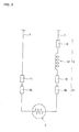
- FIG. 3 is a schematic view of the electrical connecting device 3.
- the electrical connecting device 3 is used as an electrical connecting device for a squib that energizes and ignites a gas generator in an air bag system for vehicles.
- the electrical connecting device 3 includes three terminal strips (first terminal 11, second terminal 12, and third terminal 13) separated from each other and a coil 14 that is a noise filter by which electromagnetic wave noise is removed.
- One side of the electrical connecting device 3 is connected to electric wires 7 and 7, and the other side thereof is connected to a connector element 5.
- the connector element 5 is connected to an air bag ignition device (squib) 4.
- a DC circuit that allows the combustion of the squib 4 based on a command sent from an air bag control system is formed by connecting the first terminal 11 and the second terminal 12 to a terminal 6a and a terminal 6b, respectively, of the connector element 5, i.e., by electrically and mechanically connecting the electrical connecting device 3 to the connector element 5 as shown by arrows in FIG. 3.
- a gas generating material (not shown) is ignited by this combustion, and an air bag (not shown) is inflated.
- the terminal strip unit 1 used to manufacture the electrical connecting device 3 is made up of, as shown in FIG. 1, a first terminal 11, a second terminal 12, a third terminal 13, two connection portions 15 (15a and 15b), and a base 22.
- the terminal strip unit 1 is formed by punching a sheet of metal by a single performance of press working.
- the first terminal 11 is formed as a part to be located within a range shown by two-pointed-head arrow B and includes a first terminal connection part 16 and a first wire connection part 17.
- the first terminal connection part 16 is electrically connected to a terminal 6a, which is one of a plurality of terminals of the connector element 5 (see FIG. 3).
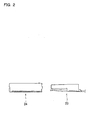
- the first terminal connection part 16 is made up of, as shown in FIG. 2, a spring part 23 whose leading end is shaped like a fork and a cover 24 made of metal (e.g., stainless steel). The cover 24 is in a state of covering the spring part 23.
- the first terminal connection part 16 and the terminal 6a of the connector element 5 are connected together, a pin (not shown) of the terminal 6a is caused to pass through a hole (not shown) formed in the leading end of the cover 24, and is pinched between the forked parts of the spring part 23, thereby an electric connection is established.
- the first terminal connection part 16 and the first wire connection part 17 are connected via a bridge 25.
- the second terminal 12 is formed as a part to be located within a range shown by two-headed-point arrow C in FIG. 1, and includes a second terminal connection part 18 and a first filter connection part 19.
- the second terminal connection part 18 is electrically connected to a terminal 6b (see FIG. 3), which is the other one of the terminals of the connector element 5. Similar to the first terminal connection part 16 of the first terminal 11, the second terminal connection part 18 is made up of the spring part 23 and the cover 24 shown in FIG. 2.
- the first filter connection part 19 of the second terminal 12, which is a part to be connected to one end of the coil 14 (see FIG. 3) serving as a noise filter, is connected to the end of the coil 14 by welding.
- the second terminal connection part 18 and the first connection part 19 are connected via a bridge 26.
- the third terminal 13 is formed as a part to be located within a range shown by two-headed-point arrow D in FIG. 1, and includes a second filter connection part 20 and a second wire connection part 21.
- the second filter connection part 20 which is a part to be connected to the other end of the coil 14 (i.e., on the opposite side of the end of the coil 14 to which the first filter connection part 19 of the second terminal 12 is connected) (see FIG. 3), and is connected to the other end of the coil 14 by welding.
- the second wire connection part 21 of the third terminal 13, which is a part to be connected to the electric wire 7 (see FIG. 3), is pressed and connected to a bare end (not shown) formed by peeling a coat of the electric wire 7.
- the second filter connection part 20 and the second wire connection part 21 are connected via a bridge 27.
- the connection portion 15 is made up of a first connection portion 15a and a second connection portion 15b, which are two connection portions by which only the terminals of two of the first to third terminals (11 to 13) are connected, so that the first terminal 11, the second terminal 12, and the third terminal 13 are formed into a unit. That is, the first terminal 11 and the second terminal 12 are connected via the first connection portion 15a. On the other hand, the second terminal 12 and the third terminal 13 are connected via the connection portion 15b. As a result, the terminal strip unit 1 has the first to third terminals (11 to 13) arranged in a row via the first connection portion 15a and the second connection portion 15b.
- the base 22 communicates with any of the first to third terminals (11 to 13) (i.e., communicates with at least two of the first to third terminals 11 to 13), and is formed as a rectilinear part. That is, the first terminal 11 has the first wire connection part 17 connected to the base 22, and, likewise, the third terminal 13 has the second wire connection part 21 connected to the base 22.
- the second terminal 12 has the first filter connection part 19 connected to the base 22.
- the third terminal 13 additionally has the second filter connection part 20 connected to the base 22.
- the terminal strip unit 1 shown in FIG. 1 is formed so that the first terminal connection part 16, the second terminal connection part 18, the first wire connection part 17, and the second wire connection part 21 are placed on mutually parallel lines, respectively. Further, the terminal strip unit 1 is formed so that a direction in which the first wire connection part 17 and the second wire connection part 21 are disposed and a direction in which the first terminal connection part 16 and the second terminal connection part 18 are disposed become opposite each other with respect to a line linking the first filter connection part 19 and the second filter connection part 20. Furthermore, the terminal strip unit 1 is formed so that the first terminal connection part 16 and the second terminal connection part 18 jut in the manner of a cantilever.
- the adjoining terminal strip units 1 communicate with each other via the bridge 28 and the base 22, thereby the structure 2 of the terminal strip units in which terminal strip units are united and arranged in a row is structured.
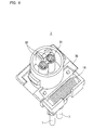
- FIG. 4 and FIG. 5 are perspective views of the electrical connecting device 3 of the embodiment shown in FIG. 3, each being viewed from a different angle.
- This electrical connecting device 3 is made up of the first to third terminals 11 to 13 that are three terminal strips formed by being separated from the terminal strip unit 1 mentioned above, the coil 14, and a housing 30.
- a pair of electric wires 7 and 7 are connected to one side of the electrical connecting device 3 (see FIG. 5), and the housing 30 formed on the other side thereof has a fitting part 31(see FIG. 4).
- the electrical connecting device 3 is connected to the connector element 5 by means of the fitting part 31 (see FIG. 3).
- the fitting part 31 has a pair of terminal holes 32 and 32.
- the first terminal connection part 16 of the first terminal 11 and the second terminal connection part 18 of the second terminal 12 are disposed in the terminal hole 32 in a state of being exposed.
- FIG. 6 is a perspective view of the first to third terminals (11 to 13) disposed in the housing 30 of the electrical connecting device 3. These constituents are disposed in the housing 30 in this state.
- FIG. 7 shows the first to third terminals 11 to 13 viewed from the direction of the arrow of FIG. 6.
- FIG. 6 and FIG. 7 do not show the coil 14 one end of which is connected to the first filter connection part 19 of the second terminal 12, and the other end of which is connected to the second filter connection part 20 of the third terminal 13.
- the electrical connecting device 3 includes the first terminal 11, the second terminal 12, and the third terminal 13. These first to third terminals (11 to 13) are formed as three terminal strips by being separated from the terminal strip unit 1 shown in FIG. 1 and being subj ected to bending work, and are included in the electrical connecting device 3.
- FIG. 8 to FIG. 10 are perspective views of the first to third terminals (11 to 13) shown in FIG. 6, respectively.
- the first terminal 11 of FIG. 8 is formed by being separated at three places along line Y-Y shown by the alternate long and two short dashes line in FIG. 1 concerning the part within the range shown by two-pointed-head arrow B of the terminal strip unit 1 of FIG. 1 and by pressing and joining the bare end part of the electric wire 7 to the first wire connection part 17.
- the second terminal 12 of FIG. 9 is formed by being separated at three places along line Y-Y shown by the alternate long and two short dashes 1 ine in FIG. 1 concerning the part within the range shown by two-pointed-head arrow C of the terminal strip unit 1 of FIG.
- the third terminal 13 of FIG. 10 is formed by being separated at four places along line Y-Y shown by the alternate long and two short dashes line in FIG. 1 concerning the part within the range shown by two-pointed-head arrow D of the terminal strip unit 1 of FIG. 1, and by being subjected to bending work at an approximately right angle at one place along line X-X shown by the alternate long and short dash line in FIG. 1, and by pressing and joining the bare end part of the electric wire 7 to the second wire connection part 21.
- the terminal strip manufacturing method is a method for manufacturing terminal strip used to manufacture the electrical connecting device 3 mentioned above. This method includes a step of forming a terminal strip unit and a step of forming a terminal strip.
- a metal plate 41 is punched by press working by use of one kind of mold 40, thereby a terminal strip unit 1 consisting of three first to third terminals (11 to 13) united is formed.
- a terminal strip unit 1 which includes first to third terminals (11 to 13) and two, that is, first and second connection portions 15a and 15b by which these three terminals are united is formed.
- the metal plate 41 is repeatedly subjected to press working by use of the mold 40, thereby the structure 2 of terminal strip units in which a plurality of terminal strip units 1 are united in series is formed.
- the cover 24 is attached to the spring part 23 of the first and second terminal connection parts (16 and 18), in addition to performing press working by use of the mold 40.
- the first to third terminals (11 to 13) united at the terminal strip unit forming step are separated from each other by a jig 42, so that three terminal strips are formed.
- the first to third terminals (11 to 13) are separated from each other along line Y-Y shown by the alternate long and two short dashes line in FIG. 1, and are subjected to bending work along line X-X shown by the alternate long and short dash line in FIG. 1. Further, electric wires 7 are pressed and to the first and second wire connection parts (17 and 21), respectively.
- the first terminal 11, the second terminal 12, and the third terminal 13 used for the electrical connecting device 3 are formed.
- the terminal strip unit 1 of this embodiment it is possible to obtain a terminal strip unit which has three kinds of terminals formed as a unit in the electrical connecting device 3 including the two pole terminals (11 and 12) connected to the connector element 5 and including the terminal 13 that connects the noise filter 14 in series. Therefore, the three kinds of terminals (11 to 13) can be simultaneously formed with one kind of mold 40, and the number of man-hours and facilities in the process for manufacturing the electrical connecting device 3 can be made efficient.
- the terminal strip unit 1 since the terminal strip unit 1 includes the first to third terminals (11 to 13) united via the two connection portions 15a and 15b by which only two terminals of the first to third terminals (11 to 13) are connected, it becomes easy to appropriately set the shape of each terminal in accordance with various design conditions of an electrical connecting device to be applied, thus making it possible to greatly heighten the design freedom. Additionally, since the structure is formed so that three terminals (11 to 13) are united via two connection portions (15a and 15b), it becomes easy to separate the terminals from each other and bend the terminals, thus making it possible to greatly reduce restrictions on processing. Therefore, according to the terminal strip unit 1, in manufacturing the electrical connecting device that has three kinds of terminal strips and a noise filter, the number of man-hours and facilities in the manufacturing process can be made efficient, and restrictions on the terminal shape and restrictions on the processing can be greatly reduced.
- each terminal (11 to 13) can be efficiently disposed in a rectilinear, limited space, and the terminals (11 to 13) can be substantially evenly spaced out.
- the terminal strip units 1 can be formed in series and efficiently by use of the mold 40 that is linearly extended and economically shaped. Therefore, when the electrical connecting device 3 is manufactured, interference between terminals that occurs when the terminals are separated from the terminal strip unit 1 or are subjected to bending work can be reduced, and the number of man-hours in the manufacturing process and facilities can be made more efficient.
- the terminal strip unit 1 since the first wire connection part 17, the second wire connection part 21, the first terminal connection part 16, and the second terminal connection part 18 are properly arranged to be parallel with each other, the first to third terminals (11 to 13) are disposed efficiently in a limited space, so that a terminal strip unit formed as a unit can be obtained.
- the terminal strip unit 1 on one side with respect to a line linking the first filter connection part 19 and the second filter connection part 20 together, the first and second wire connection parts (17 and 21) are disposed, whereas on the other side with respect to the line, the first and second terminal connection parts (16 and 18) are disposed in the direction opposite that of the first and second wire connection parts (17 and 21). Therefore, the first and second wire connection parts (17 and 21) having the same shape can be properly arranged on one side, and, likewise, the first and second terminal connection parts (16 and 18) having the same shape oan be properly arranged on the other side.
- the terminal connection parts and the wire connection parts are disposed to be opposite in direction to each other with respect to the line linking the first and second filter connection parts (19 and 20), the first and second wire connection parts (17 and 21) and the first and second terminal connection parts (16 and 18) can be disposed in a limited space more efficiently.
- the terminal strip unit 1 since at least two of the first to third terminals (11 to 13) communicate with the base 22, the first to third terminals (11 to 13) are united via the base 22, and are stably supported by the base 22 at at least two places. Therefore, a stable shape can be maintained as the terminal strip unit 1. Still additionally, since the base 22 is rectilinearly shaped, each terminal (11 to 13) united with the base 22 is efficiently rectilinearly disposed, thus making it impossible to cause restrictions on the terminal shape or restrictions on processing that result from allowing the base 22 to surround the terminals (11 to 13). Therefore, it becomes possible both to greatly lighten the restrictions on the terminal shape and the restrictions on processing and to secure a more stable shape as the terminal strip unit 1.
- the first and second wire connection parts (17 and 21) having the same shape can be united with the base 22 in a state of being properly arranged. Therefore, the first and second wire connection parts (17 and 21) can be efficiently disposed in a limited space, and a waste of materials can be prevented from being caused at places communicating with the base 22.
- the terminal strip unit 1 since the first filter connection part 19 is formed to communicate with the base 22, the second terminal 12 is also united directly with the base 22, and a more stable shape can be maintained as the terminal strip unit 1.
- the terminal strip unit 1 since the leading end side of the first and second terminal connection parts (16 and 18) juts in the manner of a cantilever, necessary processing can be easily applied to the leading ends of the first and second terminal connection parts (16 and 18) while keeping the state of being united as the terminal strip unit 1.
- the terminal strip unit 1 since the terminal strip unit 1 is formed by being punched from the metal plate 41 by a single performance of press working, it is possible tomanufacture the terminal strip unit 1 including the three terminals (11 to 13) efficiently united by one kind of mold 40.
- a terminal strip unit structure in which a plurality of terminal strip units 1 are united is formed, a plurality of electrical connecting devices 3 can be efficiently manufactured. Therefore, the process for manufacturing the electrical connecting devices 3 can be made more efficient. Additionally, since a terminal strip unit structure 2 is formed by repeatedly using the mold 40 that forms a terminal strip unit 1 with respect a metal plate 41 used as a material, a plurality of terminal strip units 1 can be efficiently manufactured.
- each terminal strip unit 1 can be efficiently disposed in a rectilinear, limited space. Additionally, since the terminal strip unit structure 2 is formed by repeatedly using the mold 40 that forms a terminal strip unit 1 with respect a metal plate 41 that is a rectilinearly extended material, a plurality of terminal strip units 1 can be more efficiently manufactured.
- an electrical connecting device 3 including the two pole terminals (11 and 12) connected to the other connector element 5 and additionally including the terminal 13 that connects the noise filter 14 in series is manufactured by using a terminal strip unit 1 in which three kinds of terminals are united. Therefore, the formation of the terminal strip unit 1 makes it possible to simultaneously form three kinds of terminals (11 to 13) with one kind of mold 40, and the number of man-hours and facilities in the process for manufacturing the electrical connecting device 3 can be made efficient.
- the terminal strip unit 1 includes the first to third terminals (11 to 13) united via the two connection portions 15a and 15b by which only two of the first to third terminals (11 to 13) are connected, it becomes easy to appropriately set the shape of each terminal in accordance with various design conditions of an electrical connecting device to be applied, thus making it possible to greatly heighten the design freedom. Additionally, since the structure is formed so that three terminals (11 to 13) are united via two connection portions (15a and 15b), it becomes easy to separate the terminals from each other and bend the terminals, thus making it possible to greatly reduce restrictions on processing. Therefore, according to the electrical connecting device 3, in manufacturing the electrical connecting device that has three kinds of terminal strips and a noise filter, the number of man-hours and facilities in the manufacturing process can be made efficient, and restrictions on the terminal shape and restrictions on the processing can be greatly reduced.
- the terminal strip manufacturing method of this embodiment at the terminal strip unit forming step, it is possible to obtain a terminal strip unit 1 which has three kinds of terminals formed as a unit in the electrical connecting device 3 including the two pole terminals (11 and 12) connected to the other connector element 5 and additionally including the terminal 13 that connects the noise filter 14 in series. Therefore, the three kinds of terminals (11 to 13) can be simultaneously formed with one kind of mold 40, and the number of man-hours and facilities in the process for manufacturing the electrical connecting device 3 can be made efficient.
- the terminal strip unit 1 includes the first to third terminals (11 to 13) united via the two connection portions 15a and 15b by which only two of the first to third terminals 11 to 13 are connected together, it becomes easy to appropriately set the shape of each terminal in accordance with various design conditions of an electrical connecting device to be applied, thus making it possible to greatly heighten the design freedom. Additionally, since the structure is formed so that three terminals (11 to 13) are united via two connection portions (15a and 15b), it becomes easy to separate the terminals from each other and bend the terminals, thus making it possible to greatly reduce restrictions on processing.
- the terminal strip manufacturing method of this embodiment in manufacturing the electrical connecting device that has three kinds of terminal strips and a noise filter, the number of man-hours and facilities in the manufacturing process can be made efficient, and restrictions on the terminal shape and restrictions on the processing can be greatly lightened.
- the present invention can be widely used in an electrical connecting device which includes three terminal strips divided from each other and a noise filter and which has its one side connected to electric wires and the other side connected to a connector element and in a method for manufacturing the electrical connecting device.
- the present invention can be applied to various connectors (electrical connecting devices) used for vehicles.
- the present invention can be more widely applied to various uses, in many different environments, and for various purposes.
Landscapes
- Engineering & Computer Science (AREA)
- Manufacturing & Machinery (AREA)
- Details Of Connecting Devices For Male And Female Coupling (AREA)
- Manufacturing Of Electrical Connectors (AREA)
- Filters And Equalizers (AREA)
Abstract
Description
- The present invention relates to an electrical connecting device that includes three terminal strips separated from each other and a noise filter used to remove electromagnetic wave noise and that has its one side connected to an electric wire and the other side connected to a connector element, relates to a terminal strip unit used to manufacture the electrical connecting device, and relates to a method for manufacturing the terminal strip.
- A terminal strip unit used to manufacture an electrical connecting device is known as a conventional one. The electrical connecting device includes terminal strip and a noise filter used to remove electromagnetic wave noise. One side of the electrical connecting device is connected to an electric wire, and the other side thereof is connected to a connector element. (See
US Patent No. 6062909 .) A terminal strip unit described inUS Patent No. 6062909 is made of a metal plate. Each terminal having a predetermined shape, such as a U shape, is individually connected to a frame part that forms the periphery of the metal plate. Electric wires, noise filters, housings, etc., are attached to the metal plate in which each terminal having such a predetermined shape is connected to the frame part. An electrical connecting device is Finally produced by separating each terminal from the frame part. - Although the terminal strip unit described in the
US Patent No. 6062909 is formed as a unit, each terminal having a predetermined shape is individually connected to the frame part, and hence restrictions on the terminal shape will be caused. Therefore, in most cases, it will become difficult to appropriately set the shape of each terminal in accordance with various design conditions of an electrical connecting device to be applied. Additionally, since the terminal strip unit has a structure in which each terminal is surrounded by the frame part, many restrictions are imposed on processing when the electrical connecting device is produced. - The present invention has been made in consideration of these circumstances. It is therefore an object of the present invention to, concerning the production of an electrical connecting device including three kinds of terminal strips and a noise filter, make the number of man-hours and facilities in the manufacturing process efficient and greatly lighten restrictions on the shape of a terminal and restrictions on processing.
- The terminal strip unit of the present invention is a terminal strip unit used to manufacture an electrical connecting device that includes three terminal strips separated from each other and a noise filter used to remove electromagnetic wave noise and that has its one side connected to an electric wire and the other side connected to a connector element.
To achieve the object, the present invention has the following features. In other words, the present invention has the following features individually or in the form of an appropriate combination. - A first feature of the terminal strip unit according to the present invention to achieve the object is that the terminal strip unit comprises a first terminal including a first terminal connection part that is electrically connected to one of a plurality of terminals of the connector element and a first wire connection part that is connected to an electric wire; a second terminal including a second terminal connection part that is electrically connected to the other one of the plurality of terminals of the connector element and a first filter connection part that is connected to an end side of the noise filter; a third terminal including a second filter connection part that is connected to the other end side of the noise filter and a second wire connection part that is connected to an electric wire; and a first connection portion and a second connection portion that are two connection portions by which only two of the first to third terminals are connected so that the first, second, and third terminals are united.
- According to this structure, it is possible to obtain a terminal strip unit which has three kinds of terminals formed as a unit in the electrical connecting device including the two pole terminals connected to another connector element and including the terminal that connects the noise filter in series. Therefore, the three kinds of terminals can be simultaneously formed with one kind of mold, and the number of man-hours and facilities in the process for manufacturing the electrical connecting device can be made efficient. Additionally, since the terminal strip unit includes the first to third terminals united via the two connection portions by which only two terminals of the first to third terminals are connected, it becomes easy to appropriately set the shape of each terminal in accordance with various design conditions of an electrical connecting device to be applied, thus making it possible to greatly heighten the design freedom. Additionally, since the structure is formed so that the three terminals are united via the two connection portions, it becomes easy to separate the terminals from each other and bend the terminals, thus making it possible to greatly reduce restrictions on processing. Therefore, according to the present invention, inmanufacturing the electrical connecting device that has three kinds of terminal strips and a noise filter, the number of man-hours and facilities in the manufacturing process can be made efficient, and restrictions on the terminal shape and restrictions on the processing can be greatly lightened.
- A second feature of the terminal strip unit according to the present invention is that the first, second, and third terminals are arranged in a row via the first and second connection portions.
- According to this structure, in the terminal strip unit, since the first to third terminals are formed into a unit via the first and second connection portions and are arranged in a row, each terminal can be efficiently disposed in a rectilinear, limited space, and the terminals can be substantially evenly spaced out. Additionally, the terminal strip units can be formed in series and efficiently by use of the mold that is linearly extended and economically shaped. Therefore, when the electrical connecting device is manufactured, interference between terminals that occurs when the terminals are separated from the terminal strip unit or are subjected to bending work can be reduced, and the number of man-hours in the manufacturing process and facilities can be made more efficient.
- A third feature of the terminal strip unit according to the present invention is that the first wire connection part, the second wire connection part, the first terminal connection part, and the second terminal connection part are disposed on mutually parallel lines, respectively.
- According to this structure, since the first wire connection part, the second wire connection part, the first terminal connection part, and the second terminal connection part are properly arranged to be parallel with each other, a terminal strip unit in which the first to third terminals are disposed as a unit efficiently in a limited space can be obtained.
- A fourth feature of the terminal strip unit according to the present invention is that a direction in which the first wire connection part and the second wire connection part are arranged and a direction in which the first terminal connection part and the second terminal connection part are arranged are made opposite each other with respect to a line linking the first filter connection part and the second filter connection part.
- According to this structure, on one side with respect to a line linking the first filter connection part and the second filter connection part, the first and second wire connection parts are disposed, whereas on the other side with respect to the line, the first and second terminal connection parts are disposed in the direction opposite that of the first and second wire connection parts. Therefore, the first and second wire connection parts which are liable to have the same shape or substantially the same shape can be properly arranged on one side, and, likewise, the first and second terminal connection parts which are liable to have the same shape or substantially the same shape can be properly arranged on the other side. Still additionally, since the terminal connection parts and the wire connection parts are disposed to be opposite in direction to each other with respect to the line linking the first and second filter connection parts, the first and second wire connection parts and the first and second terminal connection parts can be disposed in a limited space more efficiently.
- A fifth feature of the terminal strip unit according to the present invention is that the terminal strip unit further comprises a base that communicates with at least two of the first, second, and third terminals and that is shaped rectilinearly.
- According to this structure, since at least two of the first to third terminals communicate with the base, the first to third terminals are united via the base, and are stably supported by the base at at least two places. Therefore, a more stable shape can be maintained as the terminal strip unit. Still additionally, since the base is rectilinearly shaped, each terminal united with the base is efficiently rectilinearly disposed, thus making it impossible to cause restrictions on the terminal shape or restrictions on processing that result from allowing the base to surround the terminals. Therefore, it becomes possible both to greatly lighten the restrictions on the terminal shape and the restrictions on processing and to secure a more stable shape as the terminal strip unit.
- A sixth feature of the terminal strip unit according to the present invention is that the first wire connection part and the second wire connection part are respectively formed to communicate with the base.
- According to this structure, the first and second wire connection parts which are liable to have the same shape or substantially the same shape can be united with the base in a state of being properly arranged. Therefore, the first and second wire connection parts can be efficiently disposed in a limited space, and a waste of materials can be prevented from being caused at places communicating with the base.
- A seventh feature of the terminal strip unit according to the present invention is that the first filter connection part is also formed to communicate with the base.
- According to this structure, since the first filter connection part is also formed to communicate with the base, the second terminal is also united directly with the base, and a more stable shape can be maintained as the terminal strip unit.
- An eighth feature of the terminal strip unit according to the present invention is that the first terminal connection part and the second terminal connection part are formed to jut in a cantilever manner.
- According to this structure, since the leading end side of the first and second terminal connection parts juts in the manner of a cantilever, necessary processing can be easily applied to the leading ends of the first and second terminal connection parts while keeping the state of being united as the terminal strip unit.
- A ninth feature of the terminal strip unit according to the present invention is that the terminal strip unit is punched from a metal plate by a single performance of press working.
- According to this structure, since the terminal strip unit is formed by being punched from the metal plate by a single performance of press working, it is possible to manufacture the terminal strip unit including the three terminals efficiently united by one kind of mold.
- A terminal strip unit structure according to the present invention to achieve the object is characterized in that a plurality of terminal strip units each of which is the terminal strip unit mentioned above are united.
- According to this structure, since a terminal strip unit structure in which a plurality of terminal strip units are united is formed, a plurality of electrical connecting devices can be efficiently manufactured. Therefore, the process for manufacturing the electrical connecting devices can be made more efficient. Additionally, since a terminal strip unit structure is formed by repeatedly using the mold that forms a terminal strip unit with respect a material, a plurality of terminal strip units can be efficiently manufactured.
- Preferably, in the terminal strip unit structure according to the present invention, the plurality of terminal strip units are united and are arranged in a row.
- According to this structure, since the terminal strip unit structure is formed so that a plurality of terminal strip units are united and are arranged in a row, each terminal strip unit canbe efficientlydisposed in a rectilinear, limited space. Additionally, since the terminal strip unit structure is formed by repeatedly using the mold that forms a terminal strip unit with respect a rectilinearly extended material, a plurality of terminal strip units can be more efficiently manufactured.
- An electrical connecting device according to the present invention includes three terminal strips separated from each other and a noise filter that removes electromagnetic wave noise, and has its one side connected to electric wires and the other side connected to a connector element, the electrical connecting device being characterized by comprising a first terminal including a first terminal connection part that is electrically connected to one of a plurality of terminals of the connector element and a first wire connection part that is connected to an electric wire; a second terminal including a second terminal connection part that is electrically connected to the other one of the plurality of terminals of the connector element and a first filter connection part that is connected to an end side of the noise filter; and a third terminal including a second filter connection part that is connected to the other end side of the noise filter and a second wire connection part that is connected to an electric wire; wherein the first, second, and third terminals are formed by being separated from a terminal strip unit in which the first, second, and third terminals are united via a first connection portion and a second connection portion that are two connection portions by which only two of the first to third terminals are connected.
- According to this structure, the electrical connecting device including the two pole terminals connected to the other connector element and additionally including the terminal that connects the noise filter in series is manufactured by using a terminal strip unit in which three kinds of terminals are united. Therefore, the formation of the terminal strip unit makes it possible to simultaneously form three kinds of terminals with one kind of mold, and the number of man-hours and facilities in the process for manufacturing the electrical connecting device can be made efficient. Additionally, since the terminal strip unit includes the first to third terminals united via the two connection portions by which only two of the first to third terminals are connected, it becomes easy to appropriately set the shape of each terminal in accordance with various design conditions of an electrical connecting device to be applied, thus making it possible to greatly heighten the design freedom. Additionally, since the structure is formed so that three terminals are united via two connection portions, it becomes easy to separate the terminals from each other and bend the terminals, thus making it possible to greatly reduce restrictions on processing. Therefore, according to the present invention, in manufacturing the electrical connecting device that has three kinds of terminal strips and a noise filter, the number of man-hours and facilities in the manufacturing process can be made efficient, and restrictions on the terminal shape and restrictions on the processing can be greatly lightened.
- A terminal strip manufacturing method according to the present invention is a method for manufacturing terminal strip used to manufacture an electrical connecting device, the electrical connecting device including three terminal strips separated from each other and a noise filter that removes electromagnetic wave noise, one side of the electrical connecting device being connected to electric wires, the other side of the electrical connecting device being connected to a connector element, and the method is characterized by comprising a terminal strip unit forming step of forming a terminal strip unit, which includes three terminals, i.e., a first terminal, a second terminal, and a third terminal, are united, by punching a metal plate by press working; and a terminal strip forming step of forming three terminal strips by separating the first, second, and third terminals united at the terminal strip unit forming step from each other; wherein the terminal strip unit is formed at the terminal strip unit forming step, the terminal strip unit being made up of the first terminal including a first terminal connection part that is electrically connected to one of a plurality of terminals of the connector element and a first wire connection part that is connected to an electric wire; the second terminal including a second terminal connection part that is electrically connected to the other one of the plurality of terminals of the connector element and a first filter connection part that is connected to an end side of the noise filter; the third terminal including a second filter connection part that is connected to the other end side of the noise filter and a second wire connection part that is connected to an electric wire; and a first connection portion and a second connection portion that are two connection portions by which only two of the first to third terminals are connected so that the first, second, and third terminals are united.
- According to this structure, at the terminal strip unit forming step, it is possible to obtain a terminal strip unit which has three kinds of terminals formed as a unit in the electrical connecting device including the two pole terminals connected to the other connector element and additionally including the terminal that connects the noise filter in series. Therefore, the three kinds of terminals can be simultaneously formed with one kind of mold, and the number of man-hours and facilities in the process for manufacturing the electrical connecting device can be made efficient. Additionally, since the terminal strip unit includes the first to third terminals united via the two connection portions by which only two of the first to third terminals are connected, it becomes easy to appropriately set the shape of each terminal in accordance with various design conditions of an electrical connecting device to be applied, thus making it possible to greatly heighten the design freedom. Additionally, since the structure is formed so that three terminals are united via two connection portions, it becomes easy to separate the terminals from each other and bend the terminals, thus making it possible to greatly reduce restrictions on processing. Therefore, according to the present invention, in manufacturing the electrical connecting device that has three kinds of terminal strips and a noise filter, the number of man-hours and facilities in the manufacturing process can be made efficient, and restrictions on the terminal shape and restrictions on the processing can be greatly lightened.
Objects, features, and advantages other than those mentioned above of the present invention will become apparent by reading the following description with reference to the accompanying drawings. -
- FIG. 1 is a plan view of a terminal strip unit according to an embodiment of the present invention;
- FIG. 2 is a view explaining a structure of a terminal connection part of the terminal strip unit of FIG. 1;
- FIG. 3 is a schematic view showing an electrical connecting device according to an embodiment of the present invention;
- FIG. 4 is a perspective view of the electrical connecting device shown in FIG. 3;
- FIG. 5 is a perspective view of the electrical connecting device shown in FIG. 3;
- FIG. 6 is a perspective view of the first to third terminals disposed in a housing of the electrical connecting device shown in FIG. 4, without changing the arrangement thereof in the housing;
- FIG. 7 is a view sowing the first to third terminals viewed from the arrow shown in FIG. 6;
- FIG. 8 is a perspective view of the first terminal of FIG. 6;
- FIG. 9 is a perspective view of the second terminal of FIG. 6;
- FIG. 10 is a perspective view of the third terminal of FIG. 6;
- FIG. 11 is an explanatory drawing for explaining a terminal strip unit forming step in a terminal strip manufacturing method according to the embodiment of the present invention; and
- FIG. 12 is an explanatory drawing for explaining a terminal strip forming step in the terminal strip manufacturing method according to the embodiment of the present invention.
- The best mode for carrying out the present invention will be described with reference to the attached drawings. The present invention can be widely applied in an electrical connecting device, which includes three terminal strips separated from each other and a noise filter that removes electromagnetic wave noise, one side of which is connected to electric wires, and the other side of which is connected to a connector element, and in a method for manufacturing the electrical connecting device. For example, the present invention can be applied to various connectors (electrical connecting devices) used in vehicles. However, without being limited to these, the present invention can be applied for various uses, in many different environments, and for various purposes.
- First, a description will be given of a terminal strip unit and a structure of the terminal strip units according to an embodiment of the present invention. FIG. 1 is a plan view showing a
terminal strip unit 1 according to this embodiment and a part of astructure 2 of the terminal strip units. Theterminal strip unit 1 shown in FIG. 1 is used to manufacture an electrical connectingdevice 3 shown in FIG. 3. The part shown by arrow "A," which has two pointed heads, in FIG. 1 corresponds to the singleterminal strip unit 1. Thestructure 2 of the terminal strip units is formed by uniting a plurality ofterminal strip units 1 and arranging theseunits 1 in a row. In other words, thestructure 2 of the terminal strip units is of a plurality ofterminal strip units 1 united and arranged sequentially repeatedly. - Herein, a general description will be given of the electrical connecting
device 3 that is one embodiment of the present invention. FIG. 3 is a schematic view of the electrical connectingdevice 3. In this embodiment, as an example, a description is given of a case in which the electrical connectingdevice 3 is used as an electrical connecting device for a squib that energizes and ignites a gas generator in an air bag system for vehicles. - As shown in FIG. 3, the electrical connecting
device 3 includes three terminal strips (first terminal 11,second terminal 12, and third terminal 13) separated from each other and acoil 14 that is a noise filter by which electromagnetic wave noise is removed. One side of the electrical connectingdevice 3 is connected toelectric wires connector element 5. Theconnector element 5 is connected to an air bag ignition device (squib) 4. A DC circuit that allows the combustion of thesquib 4 based on a command sent from an air bag control system (not shown) is formed by connecting thefirst terminal 11 and thesecond terminal 12 to a terminal 6a and a terminal 6b, respectively, of theconnector element 5, i.e., by electrically and mechanically connecting the electrical connectingdevice 3 to theconnector element 5 as shown by arrows in FIG. 3. A gas generating material (not shown) is ignited by this combustion, and an air bag (not shown) is inflated. - The
terminal strip unit 1 used to manufacture the electrical connectingdevice 3 is made up of, as shown in FIG. 1, afirst terminal 11, asecond terminal 12, athird terminal 13, two connection portions 15 (15a and 15b), and abase 22. Theterminal strip unit 1 is formed by punching a sheet of metal by a single performance of press working. - As shown in FIG. 1, the
first terminal 11 is formed as a part to be located within a range shown by two-pointed-head arrow B and includes a firstterminal connection part 16 and a firstwire connection part 17. The firstterminal connection part 16 is electrically connected to a terminal 6a, which is one of a plurality of terminals of the connector element 5 (see FIG. 3). The firstterminal connection part 16 is made up of, as shown in FIG. 2, aspring part 23 whose leading end is shaped like a fork and acover 24 made of metal (e.g., stainless steel). Thecover 24 is in a state of covering thespring part 23. When the firstterminal connection part 16 and the terminal 6a of theconnector element 5 are connected together, a pin (not shown) of the terminal 6a is caused to pass through a hole (not shown) formed in the leading end of thecover 24, and is pinched between the forked parts of thespring part 23, thereby an electric connection is established. The firstwire connection part 17 of thefirst terminal 11, which is a part to be connected to the electric wire 7 (see FIG. 3), is pressed and connected to a bare end (not shown) formed by peeling a coat of theelectric wire 7. The firstterminal connection part 16 and the firstwire connection part 17 are connected via abridge 25. - The
second terminal 12 is formed as a part to be located within a range shown by two-headed-point arrow C in FIG. 1, and includes a secondterminal connection part 18 and a firstfilter connection part 19. The secondterminal connection part 18 is electrically connected to aterminal 6b (see FIG. 3), which is the other one of the terminals of theconnector element 5. Similar to the firstterminal connection part 16 of thefirst terminal 11, the secondterminal connection part 18 is made up of thespring part 23 and thecover 24 shown in FIG. 2. The firstfilter connection part 19 of thesecond terminal 12, which is a part to be connected to one end of the coil 14 (see FIG. 3) serving as a noise filter, is connected to the end of thecoil 14 by welding. The secondterminal connection part 18 and thefirst connection part 19 are connected via abridge 26. - The
third terminal 13 is formed as a part to be located within a range shown by two-headed-point arrow D in FIG. 1, and includes a secondfilter connection part 20 and a secondwire connection part 21. The secondfilter connection part 20, which is a part to be connected to the other end of the coil 14 (i.e., on the opposite side of the end of thecoil 14 to which the firstfilter connection part 19 of thesecond terminal 12 is connected) (see FIG. 3), and is connected to the other end of thecoil 14 by welding. The secondwire connection part 21 of thethird terminal 13, which is a part to be connected to the electric wire 7 (see FIG. 3), is pressed and connected to a bare end (not shown) formed by peeling a coat of theelectric wire 7. The secondfilter connection part 20 and the secondwire connection part 21 are connected via abridge 27. - The
connection portion 15 is made up of afirst connection portion 15a and a second connection portion 15b, which are two connection portions by which only the terminals of two of the first to third terminals (11 to 13) are connected, so that thefirst terminal 11, thesecond terminal 12, and thethird terminal 13 are formed into a unit. That is, thefirst terminal 11 and thesecond terminal 12 are connected via thefirst connection portion 15a. On the other hand, thesecond terminal 12 and thethird terminal 13 are connected via the connection portion 15b. As a result, theterminal strip unit 1 has the first to third terminals (11 to 13) arranged in a row via thefirst connection portion 15a and the second connection portion 15b. - The
base 22 communicates with any of the first to third terminals (11 to 13) (i.e., communicates with at least two of the first tothird terminals 11 to 13), and is formed as a rectilinear part. That is, thefirst terminal 11 has the firstwire connection part 17 connected to thebase 22, and, likewise, thethird terminal 13 has the secondwire connection part 21 connected to thebase 22. Thesecond terminal 12 has the firstfilter connection part 19 connected to thebase 22. Thethird terminal 13 additionally has the secondfilter connection part 20 connected to thebase 22. - The
terminal strip unit 1 shown in FIG. 1 is formed so that the firstterminal connection part 16, the secondterminal connection part 18, the firstwire connection part 17, and the secondwire connection part 21 are placed on mutually parallel lines, respectively. Further, theterminal strip unit 1 is formed so that a direction in which the firstwire connection part 17 and the secondwire connection part 21 are disposed and a direction in which the firstterminal connection part 16 and the secondterminal connection part 18 are disposed become opposite each other with respect to a line linking the firstfilter connection part 19 and the secondfilter connection part 20. Furthermore, theterminal strip unit 1 is formed so that the firstterminal connection part 16 and the secondterminal connection part 18 jut in the manner of a cantilever. - As shown in FIG. 1, the adjoining
terminal strip units 1 communicate with each other via thebridge 28 and thebase 22, thereby thestructure 2 of the terminal strip units in which terminal strip units are united and arranged in a row is structured. - Next, the electrical connecting
device 3 according to this embodiment will be described in more detail. FIG. 4 and FIG. 5 are perspective views of the electrical connectingdevice 3 of the embodiment shown in FIG. 3, each being viewed from a different angle. This electrical connectingdevice 3 is made up of the first tothird terminals 11 to 13 that are three terminal strips formed by being separated from theterminal strip unit 1 mentioned above, thecoil 14, and ahousing 30. A pair ofelectric wires housing 30 formed on the other side thereof has a fitting part 31(see FIG. 4). The electrical connectingdevice 3 is connected to theconnector element 5 by means of the fitting part 31 (see FIG. 3). Thefitting part 31 has a pair ofterminal holes terminal connection part 16 of thefirst terminal 11 and the secondterminal connection part 18 of thesecond terminal 12 are disposed in theterminal hole 32 in a state of being exposed. - FIG. 6 is a perspective view of the first to third terminals (11 to 13) disposed in the
housing 30 of the electrical connectingdevice 3. These constituents are disposed in thehousing 30 in this state. FIG. 7 shows the first tothird terminals 11 to 13 viewed from the direction of the arrow of FIG. 6. FIG. 6 and FIG. 7 do not show thecoil 14 one end of which is connected to the firstfilter connection part 19 of thesecond terminal 12, and the other end of which is connected to the secondfilter connection part 20 of thethird terminal 13. - As shown in FIG. 6 and FIG. 7, the electrical connecting
device 3 includes thefirst terminal 11, thesecond terminal 12, and thethird terminal 13. These first to third terminals (11 to 13) are formed as three terminal strips by being separated from theterminal strip unit 1 shown in FIG. 1 and being subj ected to bending work, and are included in the electrical connectingdevice 3. - FIG. 8 to FIG. 10 are perspective views of the first to third terminals (11 to 13) shown in FIG. 6, respectively. The
first terminal 11 of FIG. 8 is formed by being separated at three places along line Y-Y shown by the alternate long and two short dashes line in FIG. 1 concerning the part within the range shown by two-pointed-head arrow B of theterminal strip unit 1 of FIG. 1 and by pressing and joining the bare end part of theelectric wire 7 to the firstwire connection part 17. Thesecond terminal 12 of FIG. 9 is formed by being separated at three places along line Y-Y shown by the alternate long and twoshort dashes 1 ine in FIG. 1 concerning the part within the range shown by two-pointed-head arrow C of theterminal strip unit 1 of FIG. 1 and by being subjected to bending work at one place along line X-X shown by the alternate long and short dash line in FIG. 1. Thethird terminal 13 of FIG. 10 is formed by being separated at four places along line Y-Y shown by the alternate long and two short dashes line in FIG. 1 concerning the part within the range shown by two-pointed-head arrow D of theterminal strip unit 1 of FIG. 1, and by being subjected to bending work at an approximately right angle at one place along line X-X shown by the alternate long and short dash line in FIG. 1, and by pressing and joining the bare end part of theelectric wire 7 to the secondwire connection part 21. - Next, a description will be given of a method for manufacturing terminal strip according to an embodiment of the present invention. The terminal strip manufacturing method according to the embodiment is a method for manufacturing terminal strip used to manufacture the electrical connecting
device 3 mentioned above. This method includes a step of forming a terminal strip unit and a step of forming a terminal strip. - As shown in FIG. 11, at the terminal strip unit forming step, a
metal plate 41 is punched by press working by use of one kind ofmold 40, thereby aterminal strip unit 1 consisting of three first to third terminals (11 to 13) united is formed. In more detail, at the terminal strip unit forming step, aterminal strip unit 1 which includes first to third terminals (11 to 13) and two, that is, first andsecond connection portions 15a and 15b by which these three terminals are united is formed. Thereafter, themetal plate 41 is repeatedly subjected to press working by use of themold 40, thereby thestructure 2 of terminal strip units in which a plurality ofterminal strip units 1 are united in series is formed. At the terminal strip unit forming step, thecover 24 is attached to thespring part 23 of the first and second terminal connection parts (16 and 18), in addition to performing press working by use of themold 40. - As shown in FIG. 12, at the terminal strip forming step, the first to third terminals (11 to 13) united at the terminal strip unit forming step are separated from each other by a
jig 42, so that three terminal strips are formed. At the terminal strip forming step, the first to third terminals (11 to 13) are separated from each other along line Y-Y shown by the alternate long and two short dashes line in FIG. 1, and are subjected to bending work along line X-X shown by the alternate long and short dash line in FIG. 1. Further,electric wires 7 are pressed and to the first and second wire connection parts (17 and 21), respectively. Thus, thefirst terminal 11, thesecond terminal 12, and the third terminal 13 used for the electrical connectingdevice 3 are formed. - As described above, according to the
terminal strip unit 1 of this embodiment, it is possible to obtain a terminal strip unit which has three kinds of terminals formed as a unit in the electrical connectingdevice 3 including the two pole terminals (11 and 12) connected to theconnector element 5 and including the terminal 13 that connects thenoise filter 14 in series. Therefore, the three kinds of terminals (11 to 13) can be simultaneously formed with one kind ofmold 40, and the number of man-hours and facilities in the process for manufacturing the electrical connectingdevice 3 can be made efficient. Additionally, since theterminal strip unit 1 includes the first to third terminals (11 to 13) united via the twoconnection portions 15a and 15b by which only two terminals of the first to third terminals (11 to 13) are connected, it becomes easy to appropriately set the shape of each terminal in accordance with various design conditions of an electrical connecting device to be applied, thus making it possible to greatly heighten the design freedom. Additionally, since the structure is formed so that three terminals (11 to 13) are united via two connection portions (15a and 15b), it becomes easy to separate the terminals from each other and bend the terminals, thus making it possible to greatly reduce restrictions on processing. Therefore, according to theterminal strip unit 1, in manufacturing the electrical connecting device that has three kinds of terminal strips and a noise filter, the number of man-hours and facilities in the manufacturing process can be made efficient, and restrictions on the terminal shape and restrictions on the processing can be greatly reduced. - Additionally, according to the
terminal strip unit 1, since the first to third terminals (11 to 13) are united via the first and second connection portions (15a and 15b) so as tobe arranged ina row, each terminal (11 to 13) can be efficiently disposed in a rectilinear, limited space, and the terminals (11 to 13) can be substantially evenly spaced out. Additionally, theterminal strip units 1 can be formed in series and efficiently by use of themold 40 that is linearly extended and economically shaped. Therefore, when the electrical connectingdevice 3 is manufactured, interference between terminals that occurs when the terminals are separated from theterminal strip unit 1 or are subjected to bending work can be reduced, and the number of man-hours in the manufacturing process and facilities can be made more efficient. - Still additionally, according to the
terminal strip unit 1, since the firstwire connection part 17, the secondwire connection part 21, the firstterminal connection part 16, and the secondterminal connection part 18 are properly arranged to be parallel with each other, the first to third terminals (11 to 13) are disposed efficiently in a limited space, so that a terminal strip unit formed as a unit can be obtained. - Still additionally, according to the
terminal strip unit 1, on one side with respect to a line linking the firstfilter connection part 19 and the secondfilter connection part 20 together, the first and second wire connection parts (17 and 21) are disposed, whereas on the other side with respect to the line, the first and second terminal connection parts (16 and 18) are disposed in the direction opposite that of the first and second wire connection parts (17 and 21). Therefore, the first and second wire connection parts (17 and 21) having the same shape can be properly arranged on one side, and, likewise, the first and second terminal connection parts (16 and 18) having the same shape oan be properly arranged on the other side. Still additionally, since the terminal connection parts and the wire connection parts are disposed to be opposite in direction to each other with respect to the line linking the first and second filter connection parts (19 and 20), the first and second wire connection parts (17 and 21) and the first and second terminal connection parts (16 and 18) can be disposed in a limited space more efficiently. - Still additionally, according to the
terminal strip unit 1, since at least two of the first to third terminals (11 to 13) communicate with thebase 22, the first to third terminals (11 to 13) are united via thebase 22, and are stably supported by the base 22 at at least two places. Therefore, a stable shape can be maintained as theterminal strip unit 1. Still additionally, since thebase 22 is rectilinearly shaped, each terminal (11 to 13) united with thebase 22 is efficiently rectilinearly disposed, thus making it impossible to cause restrictions on the terminal shape or restrictions on processing that result from allowing the base 22 to surround the terminals (11 to 13). Therefore, it becomes possible both to greatly lighten the restrictions on the terminal shape and the restrictions on processing and to secure a more stable shape as theterminal strip unit 1. - Still additionally, according to the
terminal strip unit 1, the first and second wire connection parts (17 and 21) having the same shape can be united with the base 22 in a state of being properly arranged. Therefore, the first and second wire connection parts (17 and 21) can be efficiently disposed in a limited space, and a waste of materials can be prevented from being caused at places communicating with thebase 22. - Still additionally, according to the
terminal strip unit 1, since the firstfilter connection part 19 is formed to communicate with thebase 22, thesecond terminal 12 is also united directly with thebase 22, and a more stable shape can be maintained as theterminal strip unit 1. - Still additionally, according to the
terminal strip unit 1, since the leading end side of the first and second terminal connection parts (16 and 18) juts in the manner of a cantilever, necessary processing can be easily applied to the leading ends of the first and second terminal connection parts (16 and 18) while keeping the state of being united as theterminal strip unit 1. - Still additionally, according to the
terminal strip unit 1, since theterminal strip unit 1 is formed by being punched from themetal plate 41 by a single performance of press working, it is possible tomanufacture theterminal strip unit 1 including the three terminals (11 to 13) efficiently united by one kind ofmold 40. - Additionally, according to the
structure 2 of terminal strip units of the embodiment mentioned above, since a terminal strip unit structure in which a plurality ofterminal strip units 1 are united is formed, a plurality of electrical connectingdevices 3 can be efficiently manufactured. Therefore, the process for manufacturing the electrical connectingdevices 3 can be made more efficient. Additionally, since a terminalstrip unit structure 2 is formed by repeatedly using themold 40 that forms aterminal strip unit 1 with respect ametal plate 41 used as a material, a plurality ofterminal strip units 1 can be efficiently manufactured. - Still additionally, according to the
structure 2 of terminal strip units, since the terminal strip unit structure is formed so that a plurality ofterminal strip units 1 are united to be arranged in a row, eachterminal strip unit 1 can be efficiently disposed in a rectilinear, limited space. Additionally, since the terminalstrip unit structure 2 is formed by repeatedly using themold 40 that forms aterminal strip unit 1 with respect ametal plate 41 that is a rectilinearly extended material, a plurality ofterminal strip units 1 can be more efficiently manufactured. - Additionally, according to the electrical connecting
device 3 of this embodiment, an electrical connectingdevice 3 including the two pole terminals (11 and 12) connected to theother connector element 5 and additionally including the terminal 13 that connects thenoise filter 14 in series is manufactured by using aterminal strip unit 1 in which three kinds of terminals are united. Therefore, the formation of theterminal strip unit 1 makes it possible to simultaneously form three kinds of terminals (11 to 13) with one kind ofmold 40, and the number of man-hours and facilities in the process for manufacturing the electrical connectingdevice 3 can be made efficient. Additionally, since theterminal strip unit 1 includes the first to third terminals (11 to 13) united via the twoconnection portions 15a and 15b by which only two of the first to third terminals (11 to 13) are connected, it becomes easy to appropriately set the shape of each terminal in accordance with various design conditions of an electrical connecting device to be applied, thus making it possible to greatly heighten the design freedom. Additionally, since the structure is formed so that three terminals (11 to 13) are united via two connection portions (15a and 15b), it becomes easy to separate the terminals from each other and bend the terminals, thus making it possible to greatly reduce restrictions on processing. Therefore, according to the electrical connectingdevice 3, in manufacturing the electrical connecting device that has three kinds of terminal strips and a noise filter, the number of man-hours and facilities in the manufacturing process can be made efficient, and restrictions on the terminal shape and restrictions on the processing can be greatly reduced. - Additionally, according to the terminal strip manufacturing method of this embodiment, at the terminal strip unit forming step, it is possible to obtain a
terminal strip unit 1 which has three kinds of terminals formed as a unit in the electrical connectingdevice 3 including the two pole terminals (11 and 12) connected to theother connector element 5 and additionally including the terminal 13 that connects thenoise filter 14 in series. Therefore, the three kinds of terminals (11 to 13) can be simultaneously formed with one kind ofmold 40, and the number of man-hours and facilities in the process for manufacturing the electrical connectingdevice 3 can be made efficient. Additionally, since theterminal strip unit 1 includes the first to third terminals (11 to 13) united via the twoconnection portions 15a and 15b by which only two of the first tothird terminals 11 to 13 are connected together, it becomes easy to appropriately set the shape of each terminal in accordance with various design conditions of an electrical connecting device to be applied, thus making it possible to greatly heighten the design freedom. Additionally, since the structure is formed so that three terminals (11 to 13) are united via two connection portions (15a and 15b), it becomes easy to separate the terminals from each other and bend the terminals, thus making it possible to greatly reduce restrictions on processing. Therefore, according to the terminal strip manufacturing method of this embodiment, in manufacturing the electrical connecting device that has three kinds of terminal strips and a noise filter, the number of man-hours and facilities in the manufacturing process can be made efficient, and restrictions on the terminal shape and restrictions on the processing can be greatly lightened. - The embodiment of the present invention has been described as above. However, the present invention is not limited to this embodiment. As a matter of course, modifications, applications, and equivalents thereof according to what is included in the appended claims, which will become apparent by reading and understanding this specification, are intended to be included in the scope of the present invention.
For example, the present invention may be embodied to have the following modifications. -
- (1) Without being limited to the embodiment mentioned above, the shapes of the first to third terminals and the shapes of the connection portions in the terminal strip unit may be widely changed within the scope of the appended claims.
-
- (2) In the embodiment mentioned above, a description has been given of an example in which the terminal strip unit includes the rectilinear base. However, without being necessarily limited to this, the terminal strip unit may have no base. Additionally, a description has been given of an example in which the first to third terminals communicate with the base. Instead, only two of the first to third terminals may communicate with the base, and places communicating with the base may be variously changed.
- The present invention can be widely used in an electrical connecting device which includes three terminal strips divided from each other and a noise filter and which has its one side connected to electric wires and the other side connected to a connector element and in a method for manufacturing the electrical connecting device. For example, the present invention can be applied to various connectors (electrical connecting devices) used for vehicles. However, without being limited to this, the present invention can be more widely applied to various uses, in many different environments, and for various purposes.
Claims (13)
- A terminal strip unit used to manufacture an electrical connecting device, the electrical connecting device including three terminal strips separated from each other and a noise filter that removes electromagnetic wave noise, one side of the electrical connecting device being connected to electric wires, the other side of the electrical connecting device being connected to a connector element, the terminal strip unit comprising:a first terminal including a first terminal connection part that is electrically connected to one of a plurality of terminals of the connector element and a first wire connection part that is connected to an electric wire;a second terminal including a second terminal connection part that is electrically connected to the other one of the plurality of terminals of the connector element and a first filter connection part that is connected to an end side of the noise filter;a third terminal including a second filter connection part that is connected to the other end side of the noise filter and a second wire connection part that is connected to an electric wire; anda first connecti on portion and a second connection portion that are two connection portions by which only two of the first to third terminals are connected so that the first, second, and third terminals are united.
- The terminal strip unit of claim 1, wherein the first, second, and third terminals are arranged in a row via the first and second connection portions.
- The terminal strip unit of claim 1, wherein the first wire connection part, the second wire connection part, the first terminal connection part, and the second terminal connection part are placed on mutually parallel lines, respectively.
- The terminal strip unit of claim 1, wherein a direction in which the first wire connection part and the second wire connection part are arranged and a direction in which the first terminal connection part and the second terminal connection part are arranged are made opposite each other with respect to a line linking the first filter connection part and the second filter connection part together.
- The terminal strip unit of claim 1, further comprising a base that communicates with at least two of the first, second, and third terminals and that is shaped rectilinearly.
- The terminal strip unit of claim 5, wherein the first wire connection part and the second wire connection part are formed to communicate with the base.
- The terminal strip unit of claim 6, wherein the first filter connection part is also formed to communicate with the base.
- The terminal stripunit of claim 1, wherein the first terminal connection part and the second terminal connection part are formed to jut in a cantilever manner.
- The terminal strip unit of claim 1 which is punched from a metal plate by a single performance of press working.
- A structure of terminal strip units, wherein a plurality of terminal strip units each of which is that of claim 1 are united.
- The structure of terminal strip units of claim 10, wherein the plurality of terminal strip units are united and are arranged in a row.
- An electrical connecting device including three terminal strips separated from each other and a noise filter that removes electromagnetic wave noise, one side of the electrical connecting device being connected to electric wires, the other side of the electrical connecting device being connected to a connector element, the electrical connecting device comprising:a first terminal including a first terminal connection part that is electrically connected to one of a plurality of terminals of the connector element and a first wire connection part that is connected to an electric wire;a second terminal including a second terminal connection part that is electrically connected to the other one of the plurality of terminals of the connector element and a first filter connection part that is connected to an end side of the noise filter; anda third terminal including a second filter connection part that is connected to the other end side of the noise filter and a second wire connection part that is connected to an electric wire;wherein the first, second, and third terminals are formed by being separated from a terminal strip unit in which the first, second, and third terminals are united via a first connection portion and a second connection portion that are two connection portions by which only two of the first to third terminals are connected.
- A method for manufacturing terminal strip used to manufacture an electrical connecting device, the electrical connecting device including three terminal strips separated from each other and a noise filter that removes electromagnetic wave noise, one side of the electrical connecting device being connected to electric wires, the other side of the electrical connecting device being connected to a connector element, the method comprising:a terminal strip unit forming step of forming a terminal strip unit, which includes three terminals, i.e., a first terminal, a second terminal, and a third terminal, are united, by punching a metal plate by press working; anda terminal strip forming step of forming three terminal strips by separating the first, second, and third terminals united at the terminal strip unit forming step from each other;wherein the terminal strip unit is formed at the terminal strip unit forming step, the terminal strip unit being made up of:the first terminal including a first terminal connection part that is electrically connected to one of a plurality of terminals of the connector element and a first wire connection part that is connected to an electric wire;the second terminal including a second terminal connection part that is electrically connected to the other one of the plurality of terminals of the connector element and a first filter connection part that is connected to an end side of the noise filter;the third terminal including a second filter connection part that is connected to the other end side of the noise filter and a second wire connection part that is connected to an electric wire; anda first connection portion and a second connection portion that are two connection portions by which only two of the first to third terminals are connected so that the first, second, and third terminals are united.
Applications Claiming Priority (1)
| Application Number | Priority Date | Filing Date | Title |
|---|---|---|---|
| JP2005151750A JP2006331754A (en) | 2005-05-25 | 2005-05-25 | Terminal piece unit, terminal piece unit structure, electrical connection device, and terminal piece manufacturing method |
Publications (2)
| Publication Number | Publication Date |
|---|---|
| EP1727247A2 true EP1727247A2 (en) | 2006-11-29 |
| EP1727247A3 EP1727247A3 (en) | 2007-12-19 |
Family
ID=36932646
Family Applications (1)
| Application Number | Title | Priority Date | Filing Date |
|---|---|---|---|
| EP06114525A Withdrawn EP1727247A3 (en) | 2005-05-25 | 2006-05-24 | Terminal strip unit and its manufacturing method, and electrical connecting device |
Country Status (2)
| Country | Link |
|---|---|
| EP (1) | EP1727247A3 (en) |
| JP (1) | JP2006331754A (en) |
Cited By (1)
| Publication number | Priority date | Publication date | Assignee | Title |
|---|---|---|---|---|
| CN107302168A (en) * | 2016-04-15 | 2017-10-27 | 庆良电子股份有限公司 | Buried insert forming method, front structure and positioning edge material |
Family Cites Families (1)
| Publication number | Priority date | Publication date | Assignee | Title |
|---|---|---|---|---|
| DE4413756C1 (en) * | 1994-04-21 | 1995-07-13 | Amphenol Tuchel Elect | Connector housing for contact set from punched grating |
-
2005
- 2005-05-25 JP JP2005151750A patent/JP2006331754A/en not_active Withdrawn
-
2006
- 2006-05-24 EP EP06114525A patent/EP1727247A3/en not_active Withdrawn
Cited By (2)
| Publication number | Priority date | Publication date | Assignee | Title |
|---|---|---|---|---|
| CN107302168A (en) * | 2016-04-15 | 2017-10-27 | 庆良电子股份有限公司 | Buried insert forming method, front structure and positioning edge material |
| CN107302168B (en) * | 2016-04-15 | 2019-05-03 | 庆良电子股份有限公司 | Method for forming embedded insert and front structure |
Also Published As
| Publication number | Publication date |
|---|---|
| EP1727247A3 (en) | 2007-12-19 |
| JP2006331754A (en) | 2006-12-07 |
Similar Documents
| Publication | Publication Date | Title |
|---|---|---|
| JP5780788B2 (en) | Bus bar, bus bar module, power supply | |
| JP4520933B2 (en) | Terminal chain, crimper for crimping the terminal chain, terminal chain manufacturing method, and connection structure of a plurality of terminal fittings and a flat circuit body | |
| US20090009977A1 (en) | Three-Dimensional Wiring Body for Mounting Electronic Component and Electronic Component Mounting Structure | |
| JP6691080B2 (en) | Conductor connection structure of plate-shaped cable | |
| US11749930B2 (en) | Joint connecter having an isolation terminal and connection terminal | |
| JP3854458B2 (en) | Terminal bracket and terminal bracket assembly method | |
| JP4014881B2 (en) | Electrical connection device | |
| JP2003346939A (en) | Socket device and lead wire connecting method for the socket device | |
| WO2018142913A1 (en) | Electric connection assembly and method for manufacturing same | |
| JP5754501B2 (en) | Relay connector terminal manufacturing method | |
| JP5976160B2 (en) | Bus bar module and power supply | |
| JP2929423B2 (en) | ID terminal | |
| JP4805729B2 (en) | Fixing method between terminal fittings and terminal fittings | |
| JP2006331754A (en) | Terminal piece unit, terminal piece unit structure, electrical connection device, and terminal piece manufacturing method | |
| JPH11154578A (en) | Method of manufacturing insulation displacement terminal | |
| US20080271913A1 (en) | Three-Dimensional Wiring Body for Mounting Electronic Component and Electronic Component Mounting Structure | |
| JP2006236873A (en) | Method for manufacturing terminal fitting and terminal fitting | |
| JPH0839603A (en) | Molding method for insert parts | |
| JP3040266U (en) | Multi-pole electrical connector plug | |
| EP4478548A1 (en) | Contact terminal for a connector and method of producing the same | |
| JP4353749B2 (en) | Wire Harness | |
| JP2947069B2 (en) | Branch junction box and crimp terminal for branch junction box | |
| JP3861752B2 (en) | Electrical junction box and manufacturing method thereof | |
| JP2022035471A (en) | Board built-in connector and method for manufacturing chain terminal of board built-in connector | |
| JP5138471B2 (en) | Electrical parts for vehicles |
Legal Events
| Date | Code | Title | Description |
|---|---|---|---|
| PUAI | Public reference made under article 153(3) epc to a published international application that has entered the european phase |
Free format text: ORIGINAL CODE: 0009012 |
|
| AK | Designated contracting states |
Kind code of ref document: A2 Designated state(s): AT BE BG CH CY CZ DE DK EE ES FI FR GB GR HU IE IS IT LI LT LU LV MC NL PL PT RO SE SI SK TR |
|
| AX | Request for extension of the european patent |
Extension state: AL BA HR MK YU |
|
| PUAL | Search report despatched |
Free format text: ORIGINAL CODE: 0009013 |
|
| AK | Designated contracting states |
Kind code of ref document: A3 Designated state(s): AT BE BG CH CY CZ DE DK EE ES FI FR GB GR HU IE IS IT LI LT LU LV MC NL PL PT RO SE SI SK TR |
|
| AX | Request for extension of the european patent |
Extension state: AL BA HR MK YU |
|
| AKX | Designation fees paid | ||
| REG | Reference to a national code |
Ref country code: DE Ref legal event code: 8566 |
|
| STAA | Information on the status of an ep patent application or granted ep patent |
Free format text: STATUS: THE APPLICATION IS DEEMED TO BE WITHDRAWN |
|
| 18D | Application deemed to be withdrawn |
Effective date: 20080620 |