EP1727165A2 - Electrolyte for double layer capacitor - Google Patents
Electrolyte for double layer capacitor Download PDFInfo
- Publication number
- EP1727165A2 EP1727165A2 EP06010863A EP06010863A EP1727165A2 EP 1727165 A2 EP1727165 A2 EP 1727165A2 EP 06010863 A EP06010863 A EP 06010863A EP 06010863 A EP06010863 A EP 06010863A EP 1727165 A2 EP1727165 A2 EP 1727165A2
- Authority
- EP
- European Patent Office
- Prior art keywords
- double layer
- layer capacitor
- electric double
- electrolytic solution
- electrolyte
- Prior art date
- Legal status (The legal status is an assumption and is not a legal conclusion. Google has not performed a legal analysis and makes no representation as to the accuracy of the status listed.)
- Withdrawn
Links
Images


Classifications
-
- H—ELECTRICITY
- H01—ELECTRIC ELEMENTS
- H01M—PROCESSES OR MEANS, e.g. BATTERIES, FOR THE DIRECT CONVERSION OF CHEMICAL ENERGY INTO ELECTRICAL ENERGY
- H01M10/00—Secondary cells; Manufacture thereof
- H01M10/05—Accumulators with non-aqueous electrolyte
- H01M10/056—Accumulators with non-aqueous electrolyte characterised by the materials used as electrolytes, e.g. mixed inorganic/organic electrolytes
- H01M10/0564—Accumulators with non-aqueous electrolyte characterised by the materials used as electrolytes, e.g. mixed inorganic/organic electrolytes the electrolyte being constituted of organic materials only
- H01M10/0566—Liquid materials
-
- H—ELECTRICITY
- H01—ELECTRIC ELEMENTS
- H01G—CAPACITORS; CAPACITORS, RECTIFIERS, DETECTORS, SWITCHING DEVICES, LIGHT-SENSITIVE OR TEMPERATURE-SENSITIVE DEVICES OF THE ELECTROLYTIC TYPE
- H01G11/00—Hybrid capacitors, i.e. capacitors having different positive and negative electrodes; Electric double-layer [EDL] capacitors; Processes for the manufacture thereof or of parts thereof
- H01G11/54—Electrolytes
- H01G11/58—Liquid electrolytes
- H01G11/62—Liquid electrolytes characterised by the solute, e.g. salts, anions or cations therein
-
- H—ELECTRICITY
- H01—ELECTRIC ELEMENTS
- H01M—PROCESSES OR MEANS, e.g. BATTERIES, FOR THE DIRECT CONVERSION OF CHEMICAL ENERGY INTO ELECTRICAL ENERGY
- H01M10/00—Secondary cells; Manufacture thereof
- H01M10/05—Accumulators with non-aqueous electrolyte
- H01M10/056—Accumulators with non-aqueous electrolyte characterised by the materials used as electrolytes, e.g. mixed inorganic/organic electrolytes
- H01M10/0564—Accumulators with non-aqueous electrolyte characterised by the materials used as electrolytes, e.g. mixed inorganic/organic electrolytes the electrolyte being constituted of organic materials only
- H01M10/0566—Liquid materials
- H01M10/0568—Liquid materials characterised by the solutes
-
- H—ELECTRICITY
- H01—ELECTRIC ELEMENTS
- H01G—CAPACITORS; CAPACITORS, RECTIFIERS, DETECTORS, SWITCHING DEVICES, LIGHT-SENSITIVE OR TEMPERATURE-SENSITIVE DEVICES OF THE ELECTROLYTIC TYPE
- H01G11/00—Hybrid capacitors, i.e. capacitors having different positive and negative electrodes; Electric double-layer [EDL] capacitors; Processes for the manufacture thereof or of parts thereof
- H01G11/54—Electrolytes
- H01G11/58—Liquid electrolytes
-
- H—ELECTRICITY
- H01—ELECTRIC ELEMENTS
- H01M—PROCESSES OR MEANS, e.g. BATTERIES, FOR THE DIRECT CONVERSION OF CHEMICAL ENERGY INTO ELECTRICAL ENERGY
- H01M2300/00—Electrolytes
- H01M2300/0017—Non-aqueous electrolytes
- H01M2300/0025—Organic electrolyte
-
- Y—GENERAL TAGGING OF NEW TECHNOLOGICAL DEVELOPMENTS; GENERAL TAGGING OF CROSS-SECTIONAL TECHNOLOGIES SPANNING OVER SEVERAL SECTIONS OF THE IPC; TECHNICAL SUBJECTS COVERED BY FORMER USPC CROSS-REFERENCE ART COLLECTIONS [XRACs] AND DIGESTS
- Y02—TECHNOLOGIES OR APPLICATIONS FOR MITIGATION OR ADAPTATION AGAINST CLIMATE CHANGE
- Y02E—REDUCTION OF GREENHOUSE GAS [GHG] EMISSIONS, RELATED TO ENERGY GENERATION, TRANSMISSION OR DISTRIBUTION
- Y02E60/00—Enabling technologies; Technologies with a potential or indirect contribution to GHG emissions mitigation
- Y02E60/10—Energy storage using batteries
-
- Y—GENERAL TAGGING OF NEW TECHNOLOGICAL DEVELOPMENTS; GENERAL TAGGING OF CROSS-SECTIONAL TECHNOLOGIES SPANNING OVER SEVERAL SECTIONS OF THE IPC; TECHNICAL SUBJECTS COVERED BY FORMER USPC CROSS-REFERENCE ART COLLECTIONS [XRACs] AND DIGESTS
- Y02—TECHNOLOGIES OR APPLICATIONS FOR MITIGATION OR ADAPTATION AGAINST CLIMATE CHANGE
- Y02E—REDUCTION OF GREENHOUSE GAS [GHG] EMISSIONS, RELATED TO ENERGY GENERATION, TRANSMISSION OR DISTRIBUTION
- Y02E60/00—Enabling technologies; Technologies with a potential or indirect contribution to GHG emissions mitigation
- Y02E60/13—Energy storage using capacitors
Definitions
- This invention relates to an electric double layer capacitor.
- EDLC electric double layer capacitors
- an electrolytic solution a nonaqueous electrolytic solution, wherein an electrolyte is dissolved in the organic solvent, is used.
- a typical electrolytic solution is a solution of tetraethylammonium tetrafluoroborate (TEA + BF 4 - ) as electrolyte, dissolved in propylene carbonate (PC) as organic solvent, or a solution of triethylmonomethylammonium tetrafluoroborate (TEMA + BF 4 - ) dissolved in propylene carbonate.
- TEA + BF 4 - tetraethylammonium tetrafluoroborate
- PC propylene carbonate
- TEMA + BF 4 - triethylmonomethylammonium tetrafluoroborate
- Electrolytic solutions containing quartenary ammonium cations are also known (e.g., JP No. 2003-243260 and JP No. 2004-87956 ).
- This invention which was conceived in view of the aforesaid problem, aims to provide an electric double layer capacitor which offers both high capacity and low impedance.
- the electric double layer capacitor relating to the invention comprises a pair of electrodes and an electrolytic solution in contact with this pair of electrodes.
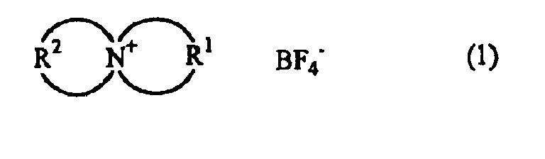
- This electrolytic solution contains the compound (1) and an organic solvent.
- R 1 is a group selected from among dimethylene, trimethylene, tetramethylene and pentamethylene
- R 2 is a tetramethylene group or a pentamethylene group.
- R 1 , R 2 are both tetramethylene groups, or R 1 is a tetramethylene group and R 2 is a pentamethylene group.
- FIG 1 is a cross-sectional view showing an electric double layer capacitor according to an example.
- FIG 2 is a table showing, for Examples 1, 2 and Comparative Example 1, the initial impedance and after energizing for 1000 hours, the electrostatic capacity, and the thickness of the cell.
- the electrolytic solution for the electric double layer capacitor relating to this example contains an electrolyte and an organic solvent.
- the electrolyte is a compound expressed by the formula (1).
- R 1 is a group selected from among dimethylene (CH 2 CH 2 ), trimethylene (CH 2 CH 2 CH 2 ), tetramethylene (CH 2 CH 2 CH 2 CH 2 ) and pentamethylene (CH 2 CH 2 CH 2 CH 2 CH 2 ), and R 2 is a tetramethylene group or a pentamethylene group.
- R 1 , R 2 are both tetramethylene groups, or R 1 is a tetramethylene group and R 2 is a pentamethylene group.
- the electrolyte is preferably a compound expressed by the following formulae (2) or (3).
- the organic solvent is not particularly limited, examples being ethylene carbonate (EC), propylene carbonate (PC), butylene carbonate (BC), sulfolane (SL) and ⁇ -butyrolactone (GBL). These may be used independently, or may be mixed in any desired ratio.
- EC ethylene carbonate
- PC propylene carbonate
- BC butylene carbonate
- SL sulfolane
- GBL ⁇ -butyrolactone
- the electrolyte concentration in the electrolytic solution is preferably within the limits of 1-3 mol/L.
- This type of electrolytic solution has a high conductance, which evidently is why it is possible to manufacture an electric double layer capacitor of low impedance and high capacity. Moreover, the dielectric strength is higher than that of an ionic solution, and equivalent to that of TEA-BF or the like.
- This electrolytic solution may take the form of a gel.
- a gel electrolytic solution which is a mixture of compound (1), an organic solvent (plasticizer) and a polymer matrix does not flow, but is a film having its own properties.
- FIG 1 is a cross-sectional view showing an electric double layer capacitor 100 relating to this example.
- the electric double layer capacitor 100 mainly comprises a laminate 20, an external container 50 accommodating the laminate 20, and a pair of leads 60, 62 connected to the laminate 20.
- the laminate 20 has a pair of electrodes 10 disposed facing each other on each side of a separator 18.
- the electrodes 10 respectively have an active material layer 14 formed on a charge collector 12.
- the active material layers 14, 14 are respectively in contact with both sides of the separator 18.
- the leads 60, 62 are respectively connected to the ends of the charge collectors 12, 12, the ends of the leads 60, 62 extending outside the external container 50.
- the charge collector 12 is formed of a metal foil, such as for example aluminum foil.
- the active material layer 14 comprises, for example, a mixture of an active material and a binder.
- the active material may be selected from among acetylene black, graphite, black lead or activated carbon, or these may be mixed and used in any desired ratio.
- the binder may be a fluororesin, such as for example polvinylidene fluoride (PVDF) or the like.
- the separator 18 is a porous insulator.
- a porous insulator a cellulose nonwoven fabric may be mentioned.
- the laminate 20 is impregnated with the aforesaid electrolytic solution for an electric double layer capacitor.
- This electrolytic solution for an electric double layer capacitor mainly impregnates the separator 18 and the active material content layer 14 in the electrode 10.
- a gel type electrolytic solution may of course be used instead.
- the external container 50 seals the laminate 20 and the electrolytic solution for an electric double layer capacitor inside.
- the external container 50 is not particularly limited provided that it can prevent leakage of the electrolytic solution for an electric double layer capacitor to the outside, and prevent entry of moisture into the electric double layer capacitor 100.
- the external container 50 as shown in FIG 1, may be a metal laminate film comprising a metal foil 52 coated on both sides by a synthetic resin film 54.
- the metal foil may be for example an aluminum foil
- the synthetic resin film may be for example polypropylene or the like.
- the leads 60, 62 are formed from a conductive material such as aluminum.
- the electric double layer capacitor 100 uses the aforesaid electrolytic solution for an electric double layer capacitor, the dual objectives of high capacity and low impedance can be realized.
- the electric double layer capacitor 100 can be manufactured as follows. First, the laminate 20, the external container 50 to which the leads 60, 62 are connected, and the electrolytic solution for an electric double layer capacitor, are respectively prepared. The laminate 20 and the external container 50 are thoroughly dried. Their moisture content can be sufficiently reduced by for example heating in air, and then heating in vacuum.
- the laminate 20 is placed inside the external container 50, the electrolytic solution for an electric double layer capacitor is dripped onto this laminate 20, and the external container 50 is sealed. This completes the manufacture of the electric double layer capacitor.
- the electric double layer capacitor 100 is not limited to the aforesaid form, and for example may comprise plural laminates 20.
- the electric double layer capacitor of Example 1 was fabricated as follows.
- This coating material was coated on one side of a 30 ⁇ m etching aluminum foil by the doctor blade method, and dried. Next, the aluminum foil was punched out in rectangular shapes having coated area and uncoated tab, and a pair of electrodes for an electric double layer capacitor was thus obtained.
- the two punched electrodes were disposed facing each other via a recycled cellulose nonwoven fabric as separator, and bonded by thermocompression to obtain a laminate.
- Aluminum leads were welded to the tabs of this laminate by ultrasonic welding.
- the laminate with attached leads was placed in a bag-like aluminum laminate film open on two of its four sides, the leads were taken out from one opening, and bonded by thermocompression on both sides of the leads.
- the electrolytic solution for an electric double layer capacitor was poured into the laminate from the last remaining opening in the aluminum laminate external container containing the laminate, and the remaining opening was sealed by vacuum thermocompression bonding to obtain the electric double layer capacitor of Example 1 as shown in FIG 1.
- the electrolytic solution for an electric double layer capacitor was a mixture of PC as organic solvent and the compound of formula (2) as electrolyte, and the electrolyte concentration was 1.5 mol/L.
- Example 2 an electric double layer capacitor was obtained as in Example 1, except that the electrolyte was the compound of formula (3).
- Comparative Example 1 the procedure was identical to that of Example 1 except that the electrolyte was tetraethylammonium tetrafluoroborate, and the electrolyte concentration was 1.0 mol/L.
- the initial impedance value at 1 kHz
- initial electrostatic capacity initial cell thickness
- impedance after energizing at 2.7 V at 70°C for 1000 hours initial cell thickness
Landscapes
- Chemical & Material Sciences (AREA)
- Engineering & Computer Science (AREA)
- Electrochemistry (AREA)
- Chemical Kinetics & Catalysis (AREA)
- Manufacturing & Machinery (AREA)
- Inorganic Chemistry (AREA)
- Physics & Mathematics (AREA)
- General Physics & Mathematics (AREA)
- Condensed Matter Physics & Semiconductors (AREA)
- General Chemical & Material Sciences (AREA)
- Power Engineering (AREA)
- Microelectronics & Electronic Packaging (AREA)
- Electric Double-Layer Capacitors Or The Like (AREA)
Abstract
Description
- This invention relates to an electric double layer capacitor.
- In recent years, much attention has been paid to electric double layer capacitors (EDLC). This type of electric double layer capacitor has a pair of electrodes, and an electrolytic solution in contact with the pair of electrodes.
- As an electrolytic solution, a nonaqueous electrolytic solution, wherein an electrolyte is dissolved in the organic solvent, is used.
- A typical electrolytic solution is a solution of tetraethylammonium tetrafluoroborate (TEA+BF4 -) as electrolyte, dissolved in propylene carbonate (PC) as organic solvent, or a solution of triethylmonomethylammonium tetrafluoroborate (TEMA+BF4 -) dissolved in propylene carbonate.
- Electrolytic solutions containing quartenary ammonium cations are also known (e.g.,
JP No. 2003-243260 JP No. 2004-87956 - In recent years, electric double layer capacitors are being required to have high capacity with low impedance. However, in earlier electric double layer capacitors, it was difficult to reconcile high capacity with low impedance.
- This invention, which was conceived in view of the aforesaid problem, aims to provide an electric double layer capacitor which offers both high capacity and low impedance.
- The Inventors, after studying the problem, found that the dual objectives of high capacity and low impedance could be achieved by using an electrolytic solution containing a specific electrolyte, and thereby arrived at the present invention.
- The electric double layer capacitor relating to the invention comprises a pair of electrodes and an electrolytic solution in contact with this pair of electrodes. This electrolytic solution contains the compound (1) and an organic solvent.
- Here, R1 is a group selected from among dimethylene, trimethylene, tetramethylene and pentamethylene, and R2 is a tetramethylene group or a pentamethylene group.

- Here, preferably, R1, R2 are both tetramethylene groups, or R1 is a tetramethylene group and R2 is a pentamethylene group.
- An electric double layer capacitor which admirably realizes both high capacity and low impedance can thereby be manufactured.
- FIG 1 is a cross-sectional view showing an electric double layer capacitor according to an example.
- FIG 2 is a table showing, for Examples 1, 2 and Comparative Example 1, the initial impedance and after energizing for 1000 hours, the electrostatic capacity, and the thickness of the cell.
- The electrolytic solution for the electric double layer capacitor relating to this example will now be described. The electrolytic solution for the electric double layer capacitor relating to this example contains an electrolyte and an organic solvent.
- The electrolyte is a compound expressed by the formula (1). Here, R1 is a group selected from among dimethylene (CH2CH2), trimethylene (CH2CH2CH2), tetramethylene (CH2CH2CH2CH2) and pentamethylene (CH2CH2CH2CH2CH2), and R2 is a tetramethylene group or a pentamethylene group.

- Here, preferably, R1, R2 are both tetramethylene groups, or R1 is a tetramethylene group and R2 is a pentamethylene group. In other words, the electrolyte is preferably a compound expressed by the following formulae (2) or (3).


- The organic solvent is not particularly limited, examples being ethylene carbonate (EC), propylene carbonate (PC), butylene carbonate (BC), sulfolane (SL) and γ-butyrolactone (GBL). These may be used independently, or may be mixed in any desired ratio.
- The electrolyte concentration in the electrolytic solution is preferably within the limits of 1-3 mol/L.
- This type of electrolytic solution has a high conductance, which evidently is why it is possible to manufacture an electric double layer capacitor of low impedance and high capacity. Moreover, the dielectric strength is higher than that of an ionic solution, and equivalent to that of TEA-BF or the like.
- This electrolytic solution may take the form of a gel. For example, a gel electrolytic solution which is a mixture of compound (1), an organic solvent (plasticizer) and a polymer matrix does not flow, but is a film having its own properties.
- An example of the electric double layer capacitor according to this example will next be described.
- FIG 1 is a cross-sectional view showing an electric
double layer capacitor 100 relating to this example. - The electric
double layer capacitor 100 mainly comprises a laminate 20, an external container 50 accommodating the laminate 20, and a pair ofleads - The laminate 20 has a pair of
electrodes 10 disposed facing each other on each side of a separator 18. Theelectrodes 10 respectively have anactive material layer 14 formed on acharge collector 12. Theactive material layers leads charge collectors leads - The
charge collector 12 is formed of a metal foil, such as for example aluminum foil. - The
active material layer 14 comprises, for example, a mixture of an active material and a binder. The active material may be selected from among acetylene black, graphite, black lead or activated carbon, or these may be mixed and used in any desired ratio. The binder may be a fluororesin, such as for example polvinylidene fluoride (PVDF) or the like. - The separator 18 is a porous insulator. As an example of a porous insulator, a cellulose nonwoven fabric may be mentioned.
- The laminate 20 is impregnated with the aforesaid electrolytic solution for an electric double layer capacitor. This electrolytic solution for an electric double layer capacitor mainly impregnates the separator 18 and the active
material content layer 14 in theelectrode 10. A gel type electrolytic solution may of course be used instead. - The external container 50 seals the laminate 20 and the electrolytic solution for an electric double layer capacitor inside. The external container 50 is not particularly limited provided that it can prevent leakage of the electrolytic solution for an electric double layer capacitor to the outside, and prevent entry of moisture into the electric
double layer capacitor 100. The external container 50, as shown in FIG 1, may be a metal laminate film comprising a metal foil 52 coated on both sides by asynthetic resin film 54. The metal foil may be for example an aluminum foil, and the synthetic resin film may be for example polypropylene or the like. - The
leads - Since the electric
double layer capacitor 100 uses the aforesaid electrolytic solution for an electric double layer capacitor, the dual objectives of high capacity and low impedance can be realized. - The electric
double layer capacitor 100 can be manufactured as follows. First, the laminate 20, the external container 50 to which the leads 60, 62 are connected, and the electrolytic solution for an electric double layer capacitor, are respectively prepared. The laminate 20 and the external container 50 are thoroughly dried. Their moisture content can be sufficiently reduced by for example heating in air, and then heating in vacuum. - Next, the laminate 20 is placed inside the external container 50, the electrolytic solution for an electric double layer capacitor is dripped onto this laminate 20, and the external container 50 is sealed. This completes the manufacture of the electric double layer capacitor.
- The electric
double layer capacitor 100 is not limited to the aforesaid form, and for example may comprise plural laminates 20. - EXAMPLES
- Example 1
- The electric double layer capacitor of Example 1 was fabricated as follows.
- Manufacture of electrode
- A coating material was prepared by mixing acetylene black as active material and PVDF as binder in the ratio active material:binder =80:20, adding N-methylpyrrolidone to the mixture, and kneading.
- This coating material was coated on one side of a 30 µm etching aluminum foil by the doctor blade method, and dried. Next, the aluminum foil was punched out in rectangular shapes having coated area and uncoated tab, and a pair of electrodes for an electric double layer capacitor was thus obtained.
- Manufacture of cell
- The two punched electrodes were disposed facing each other via a recycled cellulose nonwoven fabric as separator, and bonded by thermocompression to obtain a laminate. Aluminum leads were welded to the tabs of this laminate by ultrasonic welding. The laminate with attached leads was placed in a bag-like aluminum laminate film open on two of its four sides, the leads were taken out from one opening, and bonded by thermocompression on both sides of the leads. The electrolytic solution for an electric double layer capacitor was poured into the laminate from the last remaining opening in the aluminum laminate external container containing the laminate, and the remaining opening was sealed by vacuum thermocompression bonding to obtain the electric double layer capacitor of Example 1 as shown in FIG 1. The electrolytic solution for an electric double layer capacitor was a mixture of PC as organic solvent and the compound of formula (2) as electrolyte, and the electrolyte concentration was 1.5 mol/L.
- Example 2
- In Example 2, an electric double layer capacitor was obtained as in Example 1, except that the electrolyte was the compound of formula (3).
- Comparative Example 1
- In Comparative Example 1, the procedure was identical to that of Example 1 except that the electrolyte was tetraethylammonium tetrafluoroborate, and the electrolyte concentration was 1.0 mol/L.
- Properties of electric double layer capacitor
- For the electric double layer capacitors of the examples and comparative examples, the initial impedance (value at 1 kHz), initial electrostatic capacity, initial cell thickness, impedance after energizing at 2.7 V at 70°C for 1000 hours, electrostatic capacity and the thickness of the cell were measured. These values are shown in FIG. 2.
- For Examples 1 and 2, compared with Comparative Example 1, the impedance was small, electrostatic capacity was adequate and the thickness of the cell was also satisfactory.
Claims (2)
- An electric double layer capacitor comprising a pair of electrodes and an electrolytic solution in contact with said pair of electrodes, wherein:said electrolytic solution contains a compound having the formula (1) and an organic solvent. Here, R1 is a group selected from among dimethylene, trimethylene, tetramethylene and pentannethylene, and R2 is tetramethylene or pentamethylene.

- The electric double layer capacitor according to claim 1, wherein R1, R2 are both tetramethylene groups, or R1 is a tetramethylene group and R2 is a pentamethylene group.
Applications Claiming Priority (1)
| Application Number | Priority Date | Filing Date | Title |
|---|---|---|---|
| JP2005155876A JP2006332446A (en) | 2005-05-27 | 2005-05-27 | Electric double layer capacitor |
Publications (2)
| Publication Number | Publication Date |
|---|---|
| EP1727165A2 true EP1727165A2 (en) | 2006-11-29 |
| EP1727165A3 EP1727165A3 (en) | 2007-12-12 |
Family
ID=36691375
Family Applications (1)
| Application Number | Title | Priority Date | Filing Date |
|---|---|---|---|
| EP06010863A Withdrawn EP1727165A3 (en) | 2005-05-27 | 2006-05-26 | Electrolyte for double layer capacitor |
Country Status (4)
| Country | Link |
|---|---|
| US (1) | US7256981B2 (en) |
| EP (1) | EP1727165A3 (en) |
| JP (1) | JP2006332446A (en) |
| CN (1) | CN1870192A (en) |
Families Citing this family (12)
| Publication number | Priority date | Publication date | Assignee | Title |
|---|---|---|---|---|
| US7474521B2 (en) * | 2006-02-28 | 2009-01-06 | Medtronic, Inc. | High energy density capacitors and method of manufacturing |
| US8098479B1 (en) | 2008-09-19 | 2012-01-17 | Cornell Dubilier Marketing, Inc. | Capacitor having zinc coated common edge with welded aluminum terminal |
| US8619409B2 (en) * | 2008-10-01 | 2013-12-31 | Taiyo Yuden Co., Ltd. | Electrochemical device |
| KR101944863B1 (en) * | 2009-09-30 | 2019-02-01 | 가부시키가이샤 한도오따이 에네루기 켄큐쇼 | Electrochemical capacitor |
| US20110102972A1 (en) * | 2009-11-05 | 2011-05-05 | Samsung Elctro-Mechanics Co., Ltd. | Chip-type electric double layer capacitor cell and method of manufacturing the same |
| US10312028B2 (en) | 2014-06-30 | 2019-06-04 | Avx Corporation | Electrochemical energy storage devices and manufacturing methods |
| EP3459097A4 (en) | 2016-05-20 | 2020-05-06 | AVX Corporation | WATER-FREE ELECTROLYT FOR AN ULTRA-CAPACITOR |
| CN109155204B (en) | 2016-05-20 | 2020-12-22 | 阿维科斯公司 | Electrode structure for supercapacitor |
| CN109155202B (en) | 2016-05-20 | 2021-03-09 | 阿维科斯公司 | Multi-cell supercapacitor |
| MY194849A (en) | 2016-05-20 | 2022-12-19 | Kyocera Avx Components Corp | Ultracapacitor for use at high temperatures |
| US11830672B2 (en) | 2016-11-23 | 2023-11-28 | KYOCERA AVX Components Corporation | Ultracapacitor for use in a solder reflow process |
| JP6747462B2 (en) * | 2018-02-23 | 2020-08-26 | Tdk株式会社 | Electrochemical device |
Family Cites Families (13)
| Publication number | Priority date | Publication date | Assignee | Title |
|---|---|---|---|---|
| JPH04196511A (en) * | 1990-11-28 | 1992-07-16 | Murata Mfg Co Ltd | Electric double layer capacitor |
| US5754393A (en) * | 1995-03-07 | 1998-05-19 | Asahi Glass Company Ltd. | Electric double layer capacitor |
| AU2001284432A1 (en) * | 2000-09-07 | 2002-03-22 | Bridgestone Corporation | Additive for non-aqueous liquid electrolyte secondary cell, non-aqueous liquid electrolyte secondary cell, additive for non-aqueous liquid electrolyte electric double layer capacitor and non-aqueous liquid electrolyte electric double layer capacitor |
| JP2002128514A (en) * | 2000-10-16 | 2002-05-09 | Nisshinbo Ind Inc | Carbonaceous material, polarizable electrode for electric double layer capacitor and electric double layer capacitor |
| JP2002175837A (en) * | 2000-12-06 | 2002-06-21 | Nisshinbo Ind Inc | Polymer gel electrolyte, secondary battery and electric double layer capacitor |
| JP2003243260A (en) | 2001-12-11 | 2003-08-29 | Asahi Glass Co Ltd | Electric double layer capacitor |
| US6879482B2 (en) * | 2002-04-22 | 2005-04-12 | Asahi Glass Company, Limited | Electric double layer capacitor |
| US7061749B2 (en) * | 2002-07-01 | 2006-06-13 | Georgia Tech Research Corporation | Supercapacitor having electrode material comprising single-wall carbon nanotubes and process for making the same |
| JP2004087956A (en) | 2002-08-28 | 2004-03-18 | Japan Carlit Co Ltd:The | Electrolyte for electric double layer capacitor and electric double layer capacitor |
| JPWO2004059671A1 (en) * | 2002-12-26 | 2006-04-27 | 株式会社ブリヂストン | Electric double layer capacitor additive for non-aqueous electrolyte and non-aqueous electrolyte electric double layer capacitor |
| JPWO2005008700A1 (en) * | 2003-07-17 | 2006-11-02 | 旭硝子株式会社 | Electric double layer capacitor |
| EP1659598A4 (en) * | 2003-08-29 | 2010-02-17 | Japan Carlit Co Ltd | ELECTROLYTIC SOLUTION FOR A DOUBLE-LAYER ELECTRICAL CAPACITOR AND A DOUBLE-LAYER ELECTRICAL CAPACITOR |
| JPWO2005088656A1 (en) * | 2004-03-12 | 2008-01-31 | 日本カーリット株式会社 | Electrolytic solution for electric double layer capacitor and electric double layer capacitor |
-
2005
- 2005-05-27 JP JP2005155876A patent/JP2006332446A/en active Pending
-
2006
- 2006-05-26 CN CNA2006100846542A patent/CN1870192A/en active Pending
- 2006-05-26 EP EP06010863A patent/EP1727165A3/en not_active Withdrawn
- 2006-05-26 US US11/441,217 patent/US7256981B2/en active Active
Also Published As
| Publication number | Publication date |
|---|---|
| JP2006332446A (en) | 2006-12-07 |
| US7256981B2 (en) | 2007-08-14 |
| US20060274480A1 (en) | 2006-12-07 |
| EP1727165A3 (en) | 2007-12-12 |
| CN1870192A (en) | 2006-11-29 |
Similar Documents
| Publication | Publication Date | Title |
|---|---|---|
| US8593787B2 (en) | Electrochemical capacitor having lithium containing electrolyte | |
| US8520367B2 (en) | Method of manufacturing lithium ion capacitor and lithium ion capacitor manufactured using the same | |
| JP4041044B2 (en) | Method for manufacturing electrochemical device | |
| US20060039099A1 (en) | Electrical double layer capacitor | |
| KR20140007330A (en) | Supercapacitor with high specific density and energy density and method of manufacturing such supercapacitor | |
| KR20100129307A (en) | Electrode Membrane and Electrode Containing Ionic Liquid, Manufacturing Method thereof, and Storage Device | |
| US7256981B2 (en) | Electric double layer capacitor | |
| KR20160048187A (en) | Low resistance ultracapacitor electrode and manufacturing method thereof | |
| KR102386939B1 (en) | High power density integrated carbon/carbon ultracapacitors and batteries composed of ultracapacitors | |
| KR102822614B1 (en) | Supercapacitor with biasing electrode | |
| EP2939251A2 (en) | Electrochemical device and method of making the same | |
| WO2013001961A1 (en) | Insulating-adhesive-layer composition, element for electricity-storage device, electricity-storage device, and manufacturing methods therefor | |
| KR20130093805A (en) | Electrode, method for preparing the same, and super capacitor using the same | |
| JPS62200715A (en) | Electric double-layer capacitor | |
| JP2001217149A (en) | Electrical energy storing device and method of manufacturing the same | |
| KR101601795B1 (en) | Supercapacitor and manufacture method of the same | |
| CN1873867A (en) | Method for preparing electrodes of capacitor in double electrode layer | |
| JP5852881B2 (en) | LAMINATE TYPE ELECTRIC STORAGE ELEMENT AND MANUFACTURING METHOD THEREOF | |
| JP4529683B2 (en) | Electrochemical devices | |
| EP1708213B1 (en) | Electrochemical device | |
| KR100872926B1 (en) | Electrode current collector and electric double layer capacitor for electric double layer capacitor | |
| JP2010239085A (en) | Electric double layer capacitor | |
| JP2006186226A (en) | Electrochemical device and its manufacturing method | |
| JP2002289481A (en) | Activated carbonaceous structure and electric double layer capacitor using the same | |
| KR102288784B1 (en) | Electrochemical element |
Legal Events
| Date | Code | Title | Description |
|---|---|---|---|
| PUAI | Public reference made under article 153(3) epc to a published international application that has entered the european phase |
Free format text: ORIGINAL CODE: 0009012 |
|
| AK | Designated contracting states |
Kind code of ref document: A2 Designated state(s): AT BE BG CH CY CZ DE DK EE ES FI FR GB GR HU IE IS IT LI LT LU LV MC NL PL PT RO SE SI SK TR |
|
| AX | Request for extension of the european patent |
Extension state: AL BA HR MK YU |
|
| PUAL | Search report despatched |
Free format text: ORIGINAL CODE: 0009013 |
|
| AK | Designated contracting states |
Kind code of ref document: A3 Designated state(s): AT BE BG CH CY CZ DE DK EE ES FI FR GB GR HU IE IS IT LI LT LU LV MC NL PL PT RO SE SI SK TR |
|
| AX | Request for extension of the european patent |
Extension state: AL BA HR MK YU |
|
| RIC1 | Information provided on ipc code assigned before grant |
Ipc: H01M 10/40 20060101ALI20071105BHEP Ipc: H01G 9/038 20060101AFI20060731BHEP |
|
| 17P | Request for examination filed |
Effective date: 20080226 |
|
| 17Q | First examination report despatched |
Effective date: 20080407 |
|
| AKX | Designation fees paid |
Designated state(s): DE FR GB |
|
| STAA | Information on the status of an ep patent application or granted ep patent |
Free format text: STATUS: THE APPLICATION IS DEEMED TO BE WITHDRAWN |
|
| 18D | Application deemed to be withdrawn |
Effective date: 20080819 |