EP1727010A2 - Cleaning robot having body sensor - Google Patents
Cleaning robot having body sensor Download PDFInfo
- Publication number
- EP1727010A2 EP1727010A2 EP05292180A EP05292180A EP1727010A2 EP 1727010 A2 EP1727010 A2 EP 1727010A2 EP 05292180 A EP05292180 A EP 05292180A EP 05292180 A EP05292180 A EP 05292180A EP 1727010 A2 EP1727010 A2 EP 1727010A2
- Authority
- EP
- European Patent Office
- Prior art keywords
- cleaner
- sensor
- robot cleaner
- driving
- bottom plate
- Prior art date
- Legal status (The legal status is an assumption and is not a legal conclusion. Google has not performed a legal analysis and makes no representation as to the accuracy of the status listed.)
- Withdrawn
Links
- 238000004140 cleaning Methods 0.000 title description 14
- 238000013459 approach Methods 0.000 claims abstract description 16
- 239000000428 dust Substances 0.000 claims abstract description 10
- 230000005540 biological transmission Effects 0.000 claims description 6
- 239000004020 conductor Substances 0.000 claims description 3
- 238000012545 processing Methods 0.000 claims description 3
- 230000006870 function Effects 0.000 description 3
- 238000000034 method Methods 0.000 description 3
- 230000008901 benefit Effects 0.000 description 2
- 238000010276 construction Methods 0.000 description 2
- 238000010586 diagram Methods 0.000 description 2
- RYGMFSIKBFXOCR-UHFFFAOYSA-N Copper Chemical compound [Cu] RYGMFSIKBFXOCR-UHFFFAOYSA-N 0.000 description 1
- XAGFODPZIPBFFR-UHFFFAOYSA-N aluminium Chemical compound [Al] XAGFODPZIPBFFR-UHFFFAOYSA-N 0.000 description 1
- 229910052782 aluminium Inorganic materials 0.000 description 1
- 238000004891 communication Methods 0.000 description 1
- 229910052802 copper Inorganic materials 0.000 description 1
- 239000010949 copper Substances 0.000 description 1
- 230000000694 effects Effects 0.000 description 1
- 238000005265 energy consumption Methods 0.000 description 1
- 238000005516 engineering process Methods 0.000 description 1
- 230000003287 optical effect Effects 0.000 description 1
- 238000011160 research Methods 0.000 description 1
Images


Classifications
-
- G—PHYSICS
- G05—CONTROLLING; REGULATING
- G05D—SYSTEMS FOR CONTROLLING OR REGULATING NON-ELECTRIC VARIABLES
- G05D1/00—Control of position, course, altitude or attitude of land, water, air or space vehicles, e.g. using automatic pilots
- G05D1/02—Control of position or course in two dimensions
- G05D1/021—Control of position or course in two dimensions specially adapted to land vehicles
- G05D1/0259—Control of position or course in two dimensions specially adapted to land vehicles using magnetic or electromagnetic means
-
- A—HUMAN NECESSITIES
- A47—FURNITURE; DOMESTIC ARTICLES OR APPLIANCES; COFFEE MILLS; SPICE MILLS; SUCTION CLEANERS IN GENERAL
- A47L—DOMESTIC WASHING OR CLEANING; SUCTION CLEANERS IN GENERAL
- A47L9/00—Details or accessories of suction cleaners, e.g. mechanical means for controlling the suction or for effecting pulsating action; Storing devices specially adapted to suction cleaners or parts thereof; Carrying-vehicles specially adapted for suction cleaners
- A47L9/28—Installation of the electric equipment, e.g. adaptation or attachment to the suction cleaner; Controlling suction cleaners by electric means
-
- A—HUMAN NECESSITIES
- A47—FURNITURE; DOMESTIC ARTICLES OR APPLIANCES; COFFEE MILLS; SPICE MILLS; SUCTION CLEANERS IN GENERAL
- A47L—DOMESTIC WASHING OR CLEANING; SUCTION CLEANERS IN GENERAL
- A47L11/00—Machines for cleaning floors, carpets, furniture, walls, or wall coverings
Definitions
- the present invention relates generally to the field of automated cleaning devices, and in some exemplary embodiments, to a body sensor for such devices.
- a robot cleaner capable of automatically determining and performing desired operations with minimal external guidance.
- a robot cleaner automatically travels along a predetermined area for cleaning and draws in dust from a surface being cleaned such as a floor without being continuously controlled by a user, thereby cleaning the predetermined area.
- a person or pet in the cleaning area may collide with the robot cleaner as it automatically moves along, and may be injured by the collision.
- a person or pet hereinbelow, referred to as 'body'
- attempts have been made to incorporate obstacle sensors in robot cleaners.
- obstacle sensors typically perceive only obstacles in front, that is, in the movement path of the robot cleaner. Therefore, although a part of body, such as a limb, may approach or contact the bottom of the robot cleaner as it faces the surface being cleaned, obstacle sensors often do not perceive the body. Since the robot cleaner comprises dangerous parts such as a driving motor for operating the robot cleaner and wheels on the bottom portion, the body may be injured by contacting these and other parts. Accordingly, there is a need for a safety device that will prevent approach and contact of a body to dangerous areas of the robot cleaner. Such safety devices are particularly needed in homes with babies and infants.
- the present invention may solve one or more of the above problems and/or disadvantages and may provide one or more of the advantages described herein.
- a robot cleaner has a safety device which suspends driving of dangerous parts upon approach or contact of a body thereto, thereby improving safety.
- a robot cleaner comprises a driving part for movably supporting a cleaner body and supplying a driving force for operating the cleaner body; a suction part mounted on the cleaner body to draw in dust from a surface being cleaned; a body sensor mounted on the cleaner body to perceive approach or contact of at least a part of human body or pet; and a control part for turning on and off the driving part according to a signal detected by the body sensor.
- the control part turns on and off the suction part according to a signal detected by the body sensor.
- the body sensor may comprise a capacitance touch sensor.
- the capacitance touch sensor may comprise a sensing board for perceiving the approach or contact of the body; and a signal processor for processing the signal detected by the sensing board and transmitting the signal to the control part.
- the sensing board may be disposed at a dangerous area which may injure the human body by contact.
- the dangerous area may comprise the driving part.
- the cleaner body comprises a bottom plate for facing the surface being cleaned, and a cover for shutting the bottom plate
- the driving part comprises a driving motor mounted on the bottom plate, and a plurality of wheels connected with the driving part for power transmission and disposed on the bottom plate
- the sensing board is disposed on an inner side of the bottom plate, that faces the cover, and adjacent to the plurality of wheels and the driving motor and on an inner.
- the sensing board comprises a conductive material.
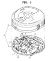
- FIG 1 is an exploded, perspective view of a robot cleaner according to an exemplary embodiment
- FIG 2 is a block diagram used to explain an exemplary embodiment of a control system that can be used with the robot cleaner of FIG. 1;
- FIG. 3 is a block diagram for explaining an exemplary embodiment of a body sensor that can be used with the embodiment of FIG. 2;
- FIG 4 is a plane view schematically showing main elements of one embodiment of the robot cleaner of FIG 1;
- FIG 5 is a sectional view of FIG. 4 cut away along a line V-V.
- a robot cleaner according to one exemplary embodiment comprises a cleaner body 10, a suction part 20, a driving part 30, an upper camera 40, a front camera 42, an obstacle sensor 50, a memory 60, a transceiver part 70, a control part 80, and a body sensor 90.
- a reference sign 'I' denotes a front or movement direction of the robot cleaner.
- the cleaner body 10 comprises a bottom plate 12 for facing a surface being cleaned G (FIG. 5) and a cover 14 for shutting the bottom plate 12.
- the suction part 20 is mounted in the cleaner body 10 to draw in dust-laden air.
- the suction part 20, a main part for the cleaning operation of the robot cleaner, can be implemented by various types of well-known suction parts of robot cleaners.
- An exemplary suction part 20 may comprise a suction motor (not shown), a suction opening (not shown) formed at the cleaner body 10 to draw in dust on the floor by a suction force generated by the suction motor, a brush (not shown) exposed through the suction opening to beat and scatter the dust, and a dust collecting chamber (not shown) for collecting therein the drawn-in dust.
- the driving part 30 (FIG. 4) comprises a driving motor 32, a driving wheel 34 and a driven wheel 36.
- a pair of the driving motors 32 are mounted to a front part of the bottom plate 12 at opposite sides and supplied with power from a power supply part (not shown).
- a pair of the driving wheels 34 are mounted to the bottom plate 12 in power connection with the driving motor 32.
- a pair of the driven wheels 36 are mounted to a rear part of the bottom plate 12 at opposite sides and connected to the driving wheels 34 through a power transmission member 38.
- a belt pulley is used for the power transmission member 38 in the embodiment shown, the power transmission member 38 may be implemented by a variety of transmitting means such as a timing belt.
- any number of motors may be used such as a single driving motor.
- a variety of designs can be used for the driving part 30 as long as they can stably move the robot cleaner.
- the driving part 30 independently rotates the driving motors 32 clockwise and counterclockwise.
- a moving direction of the robot cleaner is determined by controlling rotational speed (measured in revolutions per minute or RPM) of the respective driving motors 32.
- the upper camera 40 mounted on the bottom plate 12, photographs a ceiling image and outputs the photographed image to the control part 80.
- a fisheye lens (not shown) is provided for upper camera 40.
- the structure of the fisheye lens is disclosed (for example) in Korean Laid-Open Patent Nos. 1996-7005245 , 1997-48669 and 1994-22112 . Such lenses are commercially available and will not be described in great detail.
- the front camera 42 is mounted on the bottom plate 12 to photograph a front image and output the photographed image to the control part 80.
- obstacle sensors 50 are circumferentially disposed on an edge of the bottom plate 12 at certain intervals to transmit a signal to the outside and receive the signal as reflected.
- Obstacle sensor 50 may be implemented using a variety of technologies, such as using an optical sensor or a supersonic-wave sensor.
- the obstacle sensor 50 may be used for detecting a distance therefrom to an obstacle or a wall.
- the memory 60 stores the ceiling image photographed by the upper camera 50 and helps the control part 80 calculate position information and traveling information based on the stored image. Also, the memory 60 may store a reference value for comparison with a signal value output from the body sensor 90, and a program for comparing the signal value with the reference value.
- the transceiving part 70 sends data for transmission to an external device 72 through a transceiver (not shown) mounted in the control part 80 and transmits to the control part 80 a signal received from the external device 72 through the transceiver (not shown).
- the external device 72 may comprise, for example, a wireless communication router (not shown) and a remote controller (not shown), which are capable of input and output of data.
- control part 80 processes the signal received through the transceiver part 70 and controls the respective parts according to the signal.
- the control part 80 processes a key signal input from the key input device.
- the control part 80 locates and abstracts a position recognition mark attached to the ceiling of the cleaning area from the ceiling image photographed by the upper camera 50, and recognizes the position of the robot cleaner based on information on the position, thereby controlling the respective parts to perform their own functions using the position information.
- control part 80 controls on/off states of the driving part 30 and the suction part 20 in accordance with the signal output from the body sensor 90. Otherwise, only one of the driving part 30 and the suction part 20 may be controlled by the signal input by the body sensor 90.
- the body sensor 90 may comprise a capacitance touch sensor 90 for perceiving approach or contact of body according to variation of permittivity.
- a capacitance touch sensor 90 for perceiving approach or contact of body according to variation of permittivity.
- An example of a suitable capacitance touch sensor 90 is disclosed in Korean Utility Model Publication No. 362801 .
- the capacitance touch sensor 90 comprises a sensing board 91 for perceiving the approach or contact of the body and a signal processor 92 for processing a signal detected by the sensing board 91 and transmitting the signal to the control part 80.
- the sensing board 91 is disposed on the inner side of the bottom plate 12, which faces the cover 14, and adjacent to the driving part 30.
- the sensing board 91 may be made of conductive material such as copper and aluminum. By disposing the sensing board 91 near the driving part 30, the approach or contact of the body to the driving part 30 can be perceived. Further, being mounted on the inner side of the bottom plate 12 to face the cover 14, that is, within the cleaner body 10, the sensing board 91 is not exposed to the outside. Therefore, signal errors due to exterior moisture can be prevented.
- the present embodiment introduces the driving part 30 as a dangerous area which can hurt the body, in case that the robot cleaner further includes electrically or mechanically dangerous parts besides the driving part 30, a sensing board 91 can be disposed near these other dangerous parts.
- the signal processor 92 comprises an oscillator 93 for generating a signal of another form from an electric current detected by the sensing board 91, a rectifier 94 for converting the signal generated from the oscillator 93 to a direct current, and an output 95 for outputting the direct current converted from the signal to the control part 80. Since the capacitance touch sensor 90 is well-known in the art, detailed description of the operation and the circuit thereof will be omitted.
- FIGS. 1 through 5 The operation of a device with selected exemplary features will now be described in detail with reference to FIGS. 1 through 5.
- control part 80 controls the driving unit 30 to move along the area for cleaning according to a predetermined travel pattern, and stores in the memory 41 an image map of the ceiling based on the image photographed by the upper camera 40.
- control part 80 may draw up the image map before the cleaning work.
- the control part 80 recognizes the position of the robot cleaner using the image map while performing the work.
- the control part 80 Upon wireless input of a work request signal from the key input device or from the outside, the control part 80 recognizes the current position of the robot cleaner by comparing the image map with current images inputted from the upper camera 40 and the front camera 42, and controls the driving unit 20 to move from the recognized position along a path to a desired destination.
- the control part 80 calculates a traveling error using a traveling distance detected by an encoder and the current position which is perceived by comparing the photographed image with the stored image map. Then, the control part 80 controls the driving unit 30 to track the path to the destination by compensating with the calculated error.
- a suction motor (not shown) is driven by power supplied from the power supply part (not shown) provided within the cleaner body 10. Accordingly, a suction force is generated and the robot cleaner draws in the dust from the surface being cleaned G (FIG. 5) by the suction force, thus performing the cleaning work. Since these cleaning processes are well understood, detailed description thereof will be omitted.
- the control part 80 suspends the driving part 30 or controls the robot cleaner to divert the course and avoid the obstacle.
- the obstacle sensor 50 cannot perceive the approach or contact of an obstacle such as the body to a lower portion of the bottom plate 12 of the robot cleaner. Consequently, a sensing board 91 is provided to the lower surface of the bottom plate 12, especially the dangerous parts adjacent to the driving part 30, and to a portion provided for the user to grab for carrying the robot cleaner.
- the sensing board 91 perceives this approach.
- a signal is transmitted to the control part 80, passing through the oscillator 93, the rectifier 94 and the output 95. Therefore, the control part 80 turns off the driving part 30 and the suction part 20 to prevent the body from being injured by the driving part 30. Also, since the suction part 20 is turned off as well as the driving part 30, unnecessary energy consumption by idle operation can be prevented.
- the sensing board 91 of the body sensor 90 is mounted within the cleaner body 10, signal errors due to the moisture can be prevented, accordingly improving the performance of the body sensor 90 for detecting the approach or contact of the body.
Landscapes
- Engineering & Computer Science (AREA)
- Physics & Mathematics (AREA)
- Electromagnetism (AREA)
- Aviation & Aerospace Engineering (AREA)
- Radar, Positioning & Navigation (AREA)
- Remote Sensing (AREA)
- General Physics & Mathematics (AREA)
- Automation & Control Theory (AREA)
- Mechanical Engineering (AREA)
- Electric Vacuum Cleaner (AREA)
- Control Of Position, Course, Altitude, Or Attitude Of Moving Bodies (AREA)
- Electric Suction Cleaners (AREA)
Abstract
Description
- This application claims benefit under 35 U.S.C. § 119(a) of
Korean Patent Application No. 2005-18488, filed March 7, 2005 - The present invention relates generally to the field of automated cleaning devices, and in some exemplary embodiments, to a body sensor for such devices.
- Among general household affairs, a cleaning work is usually performed by a vacuum cleaner. However, even with the vacuum cleaner, the cleaning work is very laborious because a user has to carry the vacuum cleaner to every nook and corner.
- Accordingly, research has been conducted in the field of robot cleaners capable of automatically determining and performing desired operations with minimal external guidance. In general, a robot cleaner automatically travels along a predetermined area for cleaning and draws in dust from a surface being cleaned such as a floor without being continuously controlled by a user, thereby cleaning the predetermined area.
- However, a person or pet (hereinbelow, referred to as 'body') in the cleaning area may collide with the robot cleaner as it automatically moves along, and may be injured by the collision. To prevent such collisions, attempts have been made to incorporate obstacle sensors in robot cleaners.
- Nevertheless, obstacle sensors typically perceive only obstacles in front, that is, in the movement path of the robot cleaner. Therefore, although a part of body, such as a limb, may approach or contact the bottom of the robot cleaner as it faces the surface being cleaned, obstacle sensors often do not perceive the body. Since the robot cleaner comprises dangerous parts such as a driving motor for operating the robot cleaner and wheels on the bottom portion, the body may be injured by contacting these and other parts. Accordingly, there is a need for a safety device that will prevent approach and contact of a body to dangerous areas of the robot cleaner. Such safety devices are particularly needed in homes with babies and infants.
- It is to be understood that both the following summary and the detailed description are exemplary and explanatory and are intended to provide further explanation of the invention as claimed. Neither the summary nor the description that follows is intended to define or limit the scope of the invention to the particular features mentioned in the summary or in the description.
- In certain embodiments, the present invention may solve one or more of the above problems and/or disadvantages and may provide one or more of the advantages described herein.
- In an exemplary embodiment, a robot cleaner has a safety device which suspends driving of dangerous parts upon approach or contact of a body thereto, thereby improving safety.
- In an exemplary embodiment, a robot cleaner comprises a driving part for movably supporting a cleaner body and supplying a driving force for operating the cleaner body; a suction part mounted on the cleaner body to draw in dust from a surface being cleaned; a body sensor mounted on the cleaner body to perceive approach or contact of at least a part of human body or pet; and a control part for turning on and off the driving part according to a signal detected by the body sensor.
- According to some embodiments of the present invention, the control part turns on and off the suction part according to a signal detected by the body sensor. As an example, the body sensor may comprise a capacitance touch sensor. In this embodiment, the capacitance touch sensor may comprise a sensing board for perceiving the approach or contact of the body; and a signal processor for processing the signal detected by the sensing board and transmitting the signal to the control part. The sensing board may be disposed at a dangerous area which may injure the human body by contact. For example, the dangerous area may comprise the driving part.
- In another more specific exemplary embodiment, the cleaner body comprises a bottom plate for facing the surface being cleaned, and a cover for shutting the bottom plate, the driving part comprises a driving motor mounted on the bottom plate, and a plurality of wheels connected with the driving part for power transmission and disposed on the bottom plate, and the sensing board is disposed on an inner side of the bottom plate, that faces the cover, and adjacent to the plurality of wheels and the driving motor and on an inner. The sensing board comprises a conductive material.
- The accompanying drawings, which are incorporated herein and form a part of the specification, illustrate the present invention and, together with the description, further serve to explain the principles of the invention and to enable a person skilled in the pertinent art to make and use the invention.
- FIG 1 is an exploded, perspective view of a robot cleaner according to an exemplary embodiment;
- FIG 2 is a block diagram used to explain an exemplary embodiment of a control system that can be used with the robot cleaner of FIG. 1;
- FIG. 3 is a block diagram for explaining an exemplary embodiment of a body sensor that can be used with the embodiment of FIG. 2;
- FIG 4 is a plane view schematically showing main elements of one embodiment of the robot cleaner of FIG 1; and
- FIG 5 is a sectional view of FIG. 4 cut away along a line V-V.
- A robot cleaner will now be disclosed in terms of several exemplary embodiments. This specification discloses one or more embodiments that incorporate the features of this invention. The embodiment(s) described, and references in the specification to "one embodiment", "an embodiment", "an example embodiment", etc., indicate that the embodiment(s) described may include a particular feature, structure, or characteristic, but every embodiment may not necessarily include the particular feature, structure, or characteristic. Moreover, such phrases are not necessarily referring to the same embodiment. Further, when a particular feature, structure, or characteristic is described in connection with an embodiment, persons skilled in the art may effect such feature, structure, or characteristic in connection with other embodiments whether or not explicitly described.
- In the following description, similar drawing reference numerals may be used for the same elements even in different drawings. The embodiments described, and their detailed construction and elements, are merely provided to assist in a comprehensive understanding of the invention. Thus, it is apparent that the present invention can be carried out in a variety of ways, and does not require any of the specific features described herein. Also, well-known functions or constructions are not described in detail since they would obscure the invention with unnecessary detail.
- Referring to FIGS. 1 and 2, a robot cleaner according to one exemplary embodiment comprises a
cleaner body 10, asuction part 20, a drivingpart 30, anupper camera 40, afront camera 42, anobstacle sensor 50, amemory 60, atransceiver part 70, acontrol part 80, and abody sensor 90. A reference sign 'I' denotes a front or movement direction of the robot cleaner. - In this example, the
cleaner body 10 comprises abottom plate 12 for facing a surface being cleaned G (FIG. 5) and acover 14 for shutting thebottom plate 12. - In an embodiment, the
suction part 20 is mounted in thecleaner body 10 to draw in dust-laden air. Thesuction part 20, a main part for the cleaning operation of the robot cleaner, can be implemented by various types of well-known suction parts of robot cleaners. Anexemplary suction part 20 may comprise a suction motor (not shown), a suction opening (not shown) formed at thecleaner body 10 to draw in dust on the floor by a suction force generated by the suction motor, a brush (not shown) exposed through the suction opening to beat and scatter the dust, and a dust collecting chamber (not shown) for collecting therein the drawn-in dust. - In an embodiment, the driving part 30 (FIG. 4) comprises a
driving motor 32, adriving wheel 34 and a drivenwheel 36. A pair of thedriving motors 32 are mounted to a front part of thebottom plate 12 at opposite sides and supplied with power from a power supply part (not shown). A pair of thedriving wheels 34 are mounted to thebottom plate 12 in power connection with thedriving motor 32. A pair of the drivenwheels 36 are mounted to a rear part of thebottom plate 12 at opposite sides and connected to thedriving wheels 34 through apower transmission member 38. Although a belt pulley is used for thepower transmission member 38 in the embodiment shown, thepower transmission member 38 may be implemented by a variety of transmitting means such as a timing belt. Also, in contrast to the embodiment shown which employs a pair of driving motors, any number of motors may be used such as a single driving motor. As described above, a variety of designs can be used for the drivingpart 30 as long as they can stably move the robot cleaner. In accordance with a controlling signal of thecontrol part 80, the drivingpart 30 independently rotates thedriving motors 32 clockwise and counterclockwise. A moving direction of the robot cleaner is determined by controlling rotational speed (measured in revolutions per minute or RPM) of therespective driving motors 32. - In an embodiment, the
upper camera 40, mounted on thebottom plate 12, photographs a ceiling image and outputs the photographed image to thecontrol part 80. Preferably, a fisheye lens (not shown) is provided forupper camera 40. The structure of the fisheye lens is disclosed (for example) inKorean Laid-Open Patent Nos. 1996-7005245 1997-48669 1994-22112 - In an embodiment, the
front camera 42 is mounted on thebottom plate 12 to photograph a front image and output the photographed image to thecontrol part 80. - In an embodiment,
obstacle sensors 50 are circumferentially disposed on an edge of thebottom plate 12 at certain intervals to transmit a signal to the outside and receive the signal as reflected.Obstacle sensor 50 may be implemented using a variety of technologies, such as using an optical sensor or a supersonic-wave sensor. In addition, theobstacle sensor 50 may be used for detecting a distance therefrom to an obstacle or a wall. - In an embodiment, the
memory 60 stores the ceiling image photographed by theupper camera 50 and helps thecontrol part 80 calculate position information and traveling information based on the stored image. Also, thememory 60 may store a reference value for comparison with a signal value output from thebody sensor 90, and a program for comparing the signal value with the reference value. - In one exemplary embodiment, the
transceiving part 70 sends data for transmission to anexternal device 72 through a transceiver (not shown) mounted in thecontrol part 80 and transmits to the control part 80 a signal received from theexternal device 72 through the transceiver (not shown). Theexternal device 72 may comprise, for example, a wireless communication router (not shown) and a remote controller (not shown), which are capable of input and output of data. - In an embodiment, the
control part 80 processes the signal received through thetransceiver part 70 and controls the respective parts according to the signal. In embodiments where thecleaner body 10 further comprises a key input device (not shown) including a plurality of keys for setting functions of the robot cleaner, thecontrol part 80 processes a key signal input from the key input device. - The
control part 80 locates and abstracts a position recognition mark attached to the ceiling of the cleaning area from the ceiling image photographed by theupper camera 50, and recognizes the position of the robot cleaner based on information on the position, thereby controlling the respective parts to perform their own functions using the position information. - In addition, the
control part 80 controls on/off states of the drivingpart 30 and thesuction part 20 in accordance with the signal output from thebody sensor 90. Otherwise, only one of the drivingpart 30 and thesuction part 20 may be controlled by the signal input by thebody sensor 90. - Referring to FIGS. 3 to 5, the
body sensor 90 may comprise acapacitance touch sensor 90 for perceiving approach or contact of body according to variation of permittivity. An example of a suitablecapacitance touch sensor 90 is disclosed inKorean Utility Model Publication No. 362801 capacitance touch sensor 90 comprises asensing board 91 for perceiving the approach or contact of the body and asignal processor 92 for processing a signal detected by the sensingboard 91 and transmitting the signal to thecontrol part 80. - In some exemplary embodiments, the sensing
board 91 is disposed on the inner side of thebottom plate 12, which faces thecover 14, and adjacent to the drivingpart 30. The sensingboard 91 may be made of conductive material such as copper and aluminum. By disposing thesensing board 91 near the drivingpart 30, the approach or contact of the body to the drivingpart 30 can be perceived. Further, being mounted on the inner side of thebottom plate 12 to face thecover 14, that is, within thecleaner body 10, the sensingboard 91 is not exposed to the outside. Therefore, signal errors due to exterior moisture can be prevented. Although the present embodiment introduces the drivingpart 30 as a dangerous area which can hurt the body, in case that the robot cleaner further includes electrically or mechanically dangerous parts besides the drivingpart 30, asensing board 91 can be disposed near these other dangerous parts. - In an embodiment, the
signal processor 92 comprises anoscillator 93 for generating a signal of another form from an electric current detected by the sensingboard 91, arectifier 94 for converting the signal generated from theoscillator 93 to a direct current, and anoutput 95 for outputting the direct current converted from the signal to thecontrol part 80. Since thecapacitance touch sensor 90 is well-known in the art, detailed description of the operation and the circuit thereof will be omitted. - The operation of a device with selected exemplary features will now be described in detail with reference to FIGS. 1 through 5.
- In this operational example, the
control part 80 controls the drivingunit 30 to move along the area for cleaning according to a predetermined travel pattern, and stores in the memory 41 an image map of the ceiling based on the image photographed by theupper camera 40. Alternatively, upon receiving a wireless command from the key input device or from the outside, thecontrol part 80 may draw up the image map before the cleaning work. - For example, after completing the image map, the
control part 80 recognizes the position of the robot cleaner using the image map while performing the work. Upon wireless input of a work request signal from the key input device or from the outside, thecontrol part 80 recognizes the current position of the robot cleaner by comparing the image map with current images inputted from theupper camera 40 and thefront camera 42, and controls the drivingunit 20 to move from the recognized position along a path to a desired destination. - As an example, while the robot cleaner moves along the path to the destination, the
control part 80 calculates a traveling error using a traveling distance detected by an encoder and the current position which is perceived by comparing the photographed image with the stored image map. Then, thecontrol part 80 controls the drivingunit 30 to track the path to the destination by compensating with the calculated error. - In this example, a suction motor (not shown) is driven by power supplied from the power supply part (not shown) provided within the
cleaner body 10. Accordingly, a suction force is generated and the robot cleaner draws in the dust from the surface being cleaned G (FIG. 5) by the suction force, thus performing the cleaning work. Since these cleaning processes are well understood, detailed description thereof will be omitted. - When the
obstacle sensor 50 detects an obstacle in front during the cleaning work, thecontrol part 80 suspends the drivingpart 30 or controls the robot cleaner to divert the course and avoid the obstacle. However, theobstacle sensor 50 cannot perceive the approach or contact of an obstacle such as the body to a lower portion of thebottom plate 12 of the robot cleaner. Consequently, asensing board 91 is provided to the lower surface of thebottom plate 12, especially the dangerous parts adjacent to the drivingpart 30, and to a portion provided for the user to grab for carrying the robot cleaner. - As a part of the body approaches or contacts the
bottom plate 12, especially the drivingpart 30 of thebottom plate 12, the sensingboard 91 perceives this approach. A signal is transmitted to thecontrol part 80, passing through theoscillator 93, therectifier 94 and theoutput 95. Therefore, thecontrol part 80 turns off the drivingpart 30 and thesuction part 20 to prevent the body from being injured by the drivingpart 30. Also, since thesuction part 20 is turned off as well as the drivingpart 30, unnecessary energy consumption by idle operation can be prevented. - Moreover, in this example, because the
sensing board 91 of thebody sensor 90 is mounted within thecleaner body 10, signal errors due to the moisture can be prevented, accordingly improving the performance of thebody sensor 90 for detecting the approach or contact of the body. - While the invention has been shown and described with reference to certain embodiments thereof, it will be understood by those skilled in the art that various changes in form and details may be made therein without departing from the spirit and scope of the invention as defined by the appended claims.
Claims (9)
- A robot cleaner comprising:a driving part for movably supporting a cleaner body and supplying a driving force for operating the cleaner body;a suction part mounted on the cleaner body to draw in dust from a surface being cleaned;a body sensor mounted on the cleaner body to perceive any approach or contact of at least a part of human body or pet; anda control part for turning on and off the driving part according to a signal detected by the body sensor.
- The robot cleaner of claim 1, wherein the control part turns on and off the suction part according to a signal detected by the body sensor.
- The robot cleaner of any of claims 1 and 2, wherein the body sensor comprises a capacitance touch sensor.
- The robot cleaner of claim 3, wherein the capacitance touch sensor comprises:a sensor for perceiving the approach or contact of the body; anda signal processor for processing the signal detected by the sensing board and transmitting the signal to the control part.
- The robot cleaner of claim 4, wherein the sensor is disposed at a dangerous area which may injure the human body by contact.
- The robot cleaner of claim 5, wherein the dangerous area comprises the driving part.
- The robot cleaner of any of claims 4 to 6, wherein the cleaner body comprises a bottom plate for facing the surface being cleaned, and a cover for covering the bottom plate,
the driving part comprises a driving motor mounted on the bottom plate, and a plurality of wheels connected with the driving motor for power transmission and disposed on the bottom plate, and
the sensor is disposed on an inner side of the bottom plate, that faces the cover, and adjacent to the plurality of wheels and the driving motor and on an inner. - The robot cleaner of claim 7, wherein the sensor comprises a conductive material.
- A robot cleaner comprising:a driving part for movably supporting a cleaner body and supplying a driving force for operating the cleaner body;a suction part mounted on the cleaner body to draw in dust from a surface being cleaned;a body sensor mounted on the cleaner body to perceive any approach or contact of at least a part of human body or pet; anda control part for turning on and off the suction part according to a signal detected by the body sensor.
Applications Claiming Priority (1)
| Application Number | Priority Date | Filing Date | Title |
|---|---|---|---|
| KR1020050018488A KR100654676B1 (en) | 2005-03-07 | 2005-03-07 | Mobile robot having body sensor |
Publications (2)
| Publication Number | Publication Date |
|---|---|
| EP1727010A2 true EP1727010A2 (en) | 2006-11-29 |
| EP1727010A3 EP1727010A3 (en) | 2008-11-19 |
Family
ID=36644896
Family Applications (1)
| Application Number | Title | Priority Date | Filing Date |
|---|---|---|---|
| EP05292180A Withdrawn EP1727010A3 (en) | 2005-03-07 | 2005-10-17 | Cleaning robot having body sensor |
Country Status (7)
| Country | Link |
|---|---|
| US (1) | US20060196003A1 (en) |
| EP (1) | EP1727010A3 (en) |
| JP (1) | JP4215757B2 (en) |
| KR (1) | KR100654676B1 (en) |
| CN (1) | CN100438812C (en) |
| AU (1) | AU2005227366A1 (en) |
| RU (1) | RU2318652C2 (en) |
Families Citing this family (63)
| Publication number | Priority date | Publication date | Assignee | Title |
|---|---|---|---|---|
| US8788092B2 (en) | 2000-01-24 | 2014-07-22 | Irobot Corporation | Obstacle following sensor scheme for a mobile robot |
| US8412377B2 (en) | 2000-01-24 | 2013-04-02 | Irobot Corporation | Obstacle following sensor scheme for a mobile robot |
| US6956348B2 (en) | 2004-01-28 | 2005-10-18 | Irobot Corporation | Debris sensor for cleaning apparatus |
| US6690134B1 (en) | 2001-01-24 | 2004-02-10 | Irobot Corporation | Method and system for robot localization and confinement |
| US7571511B2 (en) | 2002-01-03 | 2009-08-11 | Irobot Corporation | Autonomous floor-cleaning robot |
| US8396592B2 (en) | 2001-06-12 | 2013-03-12 | Irobot Corporation | Method and system for multi-mode coverage for an autonomous robot |
| US7429843B2 (en) | 2001-06-12 | 2008-09-30 | Irobot Corporation | Method and system for multi-mode coverage for an autonomous robot |
| US9128486B2 (en) | 2002-01-24 | 2015-09-08 | Irobot Corporation | Navigational control system for a robotic device |
| US8428778B2 (en) | 2002-09-13 | 2013-04-23 | Irobot Corporation | Navigational control system for a robotic device |
| US8386081B2 (en) | 2002-09-13 | 2013-02-26 | Irobot Corporation | Navigational control system for a robotic device |
| US7332890B2 (en) | 2004-01-21 | 2008-02-19 | Irobot Corporation | Autonomous robot auto-docking and energy management systems and methods |
| US7720554B2 (en) | 2004-03-29 | 2010-05-18 | Evolution Robotics, Inc. | Methods and apparatus for position estimation using reflected light sources |
| EP1776624A1 (en) | 2004-06-24 | 2007-04-25 | iRobot Corporation | Programming and diagnostic tool for a mobile robot |
| US8972052B2 (en) | 2004-07-07 | 2015-03-03 | Irobot Corporation | Celestial navigation system for an autonomous vehicle |
| US7706917B1 (en) | 2004-07-07 | 2010-04-27 | Irobot Corporation | Celestial navigation system for an autonomous robot |
| US8392021B2 (en) | 2005-02-18 | 2013-03-05 | Irobot Corporation | Autonomous surface cleaning robot for wet cleaning |
| ATE468062T1 (en) | 2005-02-18 | 2010-06-15 | Irobot Corp | AUTONOMOUS SURFACE CLEANING ROBOT FOR WET AND DRY CLEANING |
| US7620476B2 (en) | 2005-02-18 | 2009-11-17 | Irobot Corporation | Autonomous surface cleaning robot for dry cleaning |
| KR100633444B1 (en) * | 2005-02-24 | 2006-10-13 | 삼성광주전자 주식회사 | Robot cleaner and method of control thereof |
| US8930023B2 (en) | 2009-11-06 | 2015-01-06 | Irobot Corporation | Localization by learning of wave-signal distributions |
| EP2270619B1 (en) | 2005-12-02 | 2013-05-08 | iRobot Corporation | Modular robot |
| EP2544065B1 (en) | 2005-12-02 | 2017-02-08 | iRobot Corporation | Robot system |
| EP2816434A3 (en) | 2005-12-02 | 2015-01-28 | iRobot Corporation | Autonomous coverage robot |
| EP2120122B1 (en) | 2005-12-02 | 2013-10-30 | iRobot Corporation | Coverage robot mobility |
| US9144360B2 (en) | 2005-12-02 | 2015-09-29 | Irobot Corporation | Autonomous coverage robot navigation system |
| EP3031377B1 (en) | 2006-05-19 | 2018-08-01 | iRobot Corporation | Removing debris from cleaning robots |
| US8417383B2 (en) | 2006-05-31 | 2013-04-09 | Irobot Corporation | Detecting robot stasis |
| KR101168481B1 (en) * | 2007-05-09 | 2012-07-26 | 아이로보트 코퍼레이션 | Autonomous coverage robot |
| DE102007059118A1 (en) * | 2007-12-07 | 2009-06-10 | Robert Bosch Gmbh | Autonomous working device |
| TW201127506A (en) * | 2010-02-11 | 2011-08-16 | cheng-xiang Yan | Thin type automatic cleaning device |
| US8800107B2 (en) | 2010-02-16 | 2014-08-12 | Irobot Corporation | Vacuum brush |
| KR20110119118A (en) * | 2010-04-26 | 2011-11-02 | 엘지전자 주식회사 | Robot cleaner, and remote monitoring system using the same |
| JP5531839B2 (en) * | 2010-07-21 | 2014-06-25 | 三菱電機株式会社 | Electric vacuum cleaner |
| KR101637359B1 (en) * | 2010-08-20 | 2016-07-07 | 엘지전자 주식회사 | Cleaner |
| CN102462451B (en) * | 2010-11-10 | 2015-04-22 | 财团法人工业技术研究院 | Vacuum cleaner and operation method thereof |
| KR101352195B1 (en) | 2012-03-08 | 2014-01-16 | 엘지전자 주식회사 | Robot cleaner |
| USD722281S1 (en) * | 2012-07-09 | 2015-02-10 | Adept Technology, Inc. | Mobile robotic platform |
| US9326654B2 (en) | 2013-03-15 | 2016-05-03 | Irobot Corporation | Roller brush for surface cleaning robots |
| TW201446208A (en) * | 2013-06-05 | 2014-12-16 | Uni Ring Tech Co Ltd | Object differential detection method and apparatus |
| JP6826804B2 (en) * | 2014-08-29 | 2021-02-10 | 東芝ライフスタイル株式会社 | Autonomous vehicle |
| CN106137043B (en) * | 2014-12-24 | 2018-09-11 | 江苏美的清洁电器股份有限公司 | The control method and control device of sweeping robot and sweeping robot |
| KR102318295B1 (en) * | 2015-01-22 | 2021-10-27 | 에브리봇 주식회사 | Robot cleaning apparatus and method for controlling the same |
| CN106137044B (en) * | 2015-04-15 | 2019-12-24 | 小米科技有限责任公司 | Automatic dust removal device |
| CN106888673A (en) * | 2015-12-17 | 2017-06-27 | 苏州宝时得电动工具有限公司 | Hay mover |
| CN109070330B (en) * | 2016-04-08 | 2022-07-15 | Groove X 株式会社 | Cognitive behavioral autonomous robot |
| WO2017200350A1 (en) | 2016-05-20 | 2017-11-23 | 엘지전자 주식회사 | Robot cleaner |
| US10463212B2 (en) | 2016-05-20 | 2019-11-05 | Lg Electronics Inc. | Autonomous cleaner |
| WO2017200344A1 (en) | 2016-05-20 | 2017-11-23 | 엘지전자 주식회사 | Robot cleaner |
| TWI698213B (en) * | 2016-05-20 | 2020-07-11 | 南韓商Lg電子股份有限公司 | Robot cleaner |
| US10420448B2 (en) | 2016-05-20 | 2019-09-24 | Lg Electronics Inc. | Autonomous cleaner |
| WO2017200348A1 (en) | 2016-05-20 | 2017-11-23 | 엘지전자 주식회사 | Robot cleaner |
| US10481611B2 (en) | 2016-05-20 | 2019-11-19 | Lg Electronics Inc. | Autonomous cleaner |
| US10524628B2 (en) | 2016-05-20 | 2020-01-07 | Lg Electronics Inc. | Autonomous cleaner |
| US10375880B2 (en) | 2016-12-30 | 2019-08-13 | Irobot Corporation | Robot lawn mower bumper system |
| DE102017203094A1 (en) * | 2017-02-24 | 2018-08-30 | Robert Bosch Gmbh | Method for protecting a body part |
| US20200245837A1 (en) * | 2017-10-13 | 2020-08-06 | Chiba Institute Of Technology | Self-propelled vacuum cleaner |
| CN109263755A (en) * | 2018-11-02 | 2019-01-25 | 博众精工科技股份有限公司 | A kind of mounting structure and AGV |
| WO2020102946A1 (en) * | 2018-11-19 | 2020-05-28 | 珊口(深圳)智能科技有限公司 | Map building method and system, positioning method and system, navigation method and system, control method and system, and mobile robot |
| CN112956953A (en) * | 2018-11-30 | 2021-06-15 | 南安市祁兴机械贸易有限公司 | Floor sweeping robot and method |
| KR102707921B1 (en) | 2019-01-22 | 2024-09-23 | 삼성전자주식회사 | Robot and method for controlling thereof |
| US11109727B2 (en) | 2019-02-28 | 2021-09-07 | Irobot Corporation | Cleaning rollers for cleaning robots |
| KR20190087355A (en) * | 2019-07-05 | 2019-07-24 | 엘지전자 주식회사 | Method for driving cleaning robot and cleaning robot which drives using regional human activity data |
| USD965656S1 (en) | 2019-10-14 | 2022-10-04 | Omron Corporation | Mobile robot |
Citations (2)
| Publication number | Priority date | Publication date | Assignee | Title |
|---|---|---|---|---|
| KR200362801Y1 (en) | 2004-06-21 | 2004-09-23 | 유건식 | Touch Sensor |
| KR100705245B1 (en) | 2005-12-19 | 2007-04-09 | 주식회사 포스코 | Method and apparatus for preventing from breakout of a segment in equipments for continuous casting |
Family Cites Families (16)
| Publication number | Priority date | Publication date | Assignee | Title |
|---|---|---|---|---|
| EP0158593B1 (en) * | 1984-04-09 | 1989-05-24 | GET Gesellschaft für Elektronik-Technologie mbH | Electronic surveillance and warning device for a manipulator |
| US4968878A (en) * | 1989-02-07 | 1990-11-06 | Transitions Research Corporation | Dual bumper-light curtain obstacle detection sensor |
| US5166679A (en) * | 1991-06-06 | 1992-11-24 | The United States Of America As Represented By The Administrator Of The National Aeronautics & Space Administration | Driven shielding capacitive proximity sensor |
| KR100213491B1 (en) * | 1997-07-01 | 1999-08-02 | 최진호 | Safety device for automatic vacuum cleaner |
| US6481515B1 (en) * | 2000-05-30 | 2002-11-19 | The Procter & Gamble Company | Autonomous mobile surface treating apparatus |
| AUPR154400A0 (en) * | 2000-11-17 | 2000-12-14 | Duplex Cleaning Machines Pty. Limited | Robot machine |
| US6883201B2 (en) * | 2002-01-03 | 2005-04-26 | Irobot Corporation | Autonomous floor-cleaning robot |
| ATE510247T1 (en) * | 2001-06-12 | 2011-06-15 | Irobot Corp | METHOD AND SYSTEM FOR MULTI-MODAL COVERING FOR AN AUTONOMOUS ROBOT |
| US7429843B2 (en) * | 2001-06-12 | 2008-09-30 | Irobot Corporation | Method and system for multi-mode coverage for an autonomous robot |
| CN1436511A (en) * | 2002-02-05 | 2003-08-20 | 海尔集团公司 | Intelligent dust collector |
| KR100466321B1 (en) * | 2002-10-31 | 2005-01-14 | 삼성광주전자 주식회사 | Robot cleaner, system thereof and method for controlling the same |
| JP2004357768A (en) * | 2003-06-02 | 2004-12-24 | Hitachi Home & Life Solutions Inc | Robot vacuum cleaner |
| KR100478681B1 (en) * | 2003-07-29 | 2005-03-25 | 삼성광주전자 주식회사 | an robot-cleaner equipped with floor-disinfecting function |
| JP2005211463A (en) * | 2004-01-30 | 2005-08-11 | Funai Electric Co Ltd | Self-propelled vacuum cleaner |
| EP1796879A2 (en) * | 2004-08-27 | 2007-06-20 | Sharper Image Corporation | Robot cleaner with improved vacuum unit |
| JP4665194B2 (en) * | 2005-05-27 | 2011-04-06 | 好高 青山 | Electrical resistance welding method and apparatus for small-diameter shaft parts |
-
2005
- 2005-03-07 KR KR1020050018488A patent/KR100654676B1/en not_active IP Right Cessation
- 2005-08-12 JP JP2005233855A patent/JP4215757B2/en not_active Expired - Fee Related
- 2005-10-14 US US11/249,545 patent/US20060196003A1/en not_active Abandoned
- 2005-10-17 EP EP05292180A patent/EP1727010A3/en not_active Withdrawn
- 2005-10-26 RU RU2005132942/02A patent/RU2318652C2/en not_active IP Right Cessation
- 2005-10-26 CN CNB2005101141690A patent/CN100438812C/en not_active Expired - Fee Related
- 2005-10-26 AU AU2005227366A patent/AU2005227366A1/en not_active Abandoned
Patent Citations (2)
| Publication number | Priority date | Publication date | Assignee | Title |
|---|---|---|---|---|
| KR200362801Y1 (en) | 2004-06-21 | 2004-09-23 | 유건식 | Touch Sensor |
| KR100705245B1 (en) | 2005-12-19 | 2007-04-09 | 주식회사 포스코 | Method and apparatus for preventing from breakout of a segment in equipments for continuous casting |
Also Published As
| Publication number | Publication date |
|---|---|
| JP4215757B2 (en) | 2009-01-28 |
| EP1727010A3 (en) | 2008-11-19 |
| US20060196003A1 (en) | 2006-09-07 |
| RU2005132942A (en) | 2007-05-10 |
| CN100438812C (en) | 2008-12-03 |
| AU2005227366A1 (en) | 2006-09-21 |
| CN1830375A (en) | 2006-09-13 |
| JP2006247368A (en) | 2006-09-21 |
| KR20060097782A (en) | 2006-09-18 |
| KR100654676B1 (en) | 2006-12-08 |
| RU2318652C2 (en) | 2008-03-10 |
Similar Documents
| Publication | Publication Date | Title |
|---|---|---|
| EP1727010A2 (en) | Cleaning robot having body sensor | |
| KR101771869B1 (en) | Traveling body device | |
| JP2846835B2 (en) | Charge induction device and method for robot vacuum cleaner | |
| KR100815570B1 (en) | System for robot cleaner and control methord thereof | |
| RU2272557C2 (en) | Robot-cleaner with floor disinfection function | |
| US6841963B2 (en) | Robot cleaner, system thereof and method for controlling same | |
| US6901624B2 (en) | Self-moving cleaner | |
| US20070233319A1 (en) | System and method for returning mobile robot to charging stand | |
| US20020060542A1 (en) | Mobile robot system using RF module | |
| JP2004237075A (en) | Robot cleaner system provided with external charger and connection method for robot cleaner to external charger | |
| JP2002355204A (en) | Traveling vacuum cleaner | |
| KR20190035376A (en) | A robot cleaner and control method thereof | |
| JP2006043071A (en) | Self-propelled cleaner | |
| US20050212680A1 (en) | Self-propelled cleaner | |
| SE523915C2 (en) | Cleaning robot system with external charging device and method of docking charging device. | |
| JP2007175286A (en) | Automatic cleaning system | |
| AU9741301A (en) | Robot cleaner, system employing the same and method for reconnecting to external recharging device | |
| US10765284B2 (en) | Cleaning robot | |
| JP2017064064A (en) | Vacuum cleaner | |
| JP3721939B2 (en) | Mobile work robot | |
| US20060238374A1 (en) | Autonomous cleaner | |
| KR101223480B1 (en) | Mobile robot and controlling method of the same | |
| KR102320560B1 (en) | A moving robot and controlling method for the moving robot | |
| JP2003050633A (en) | Autonomous moving device | |
| KR101479238B1 (en) | Robot cleaner and control method of the same of |
Legal Events
| Date | Code | Title | Description |
|---|---|---|---|
| PUAI | Public reference made under article 153(3) epc to a published international application that has entered the european phase |
Free format text: ORIGINAL CODE: 0009012 |
|
| AK | Designated contracting states |
Kind code of ref document: A2 Designated state(s): AT BE BG CH CY CZ DE DK EE ES FI FR GB GR HU IE IS IT LI LT LU LV MC NL PL PT RO SE SI SK TR |
|
| AX | Request for extension of the european patent |
Extension state: AL BA HR MK YU |
|
| PUAL | Search report despatched |
Free format text: ORIGINAL CODE: 0009013 |
|
| AK | Designated contracting states |
Kind code of ref document: A3 Designated state(s): AT BE BG CH CY CZ DE DK EE ES FI FR GB GR HU IE IS IT LI LT LU LV MC NL PL PT RO SE SI SK TR |
|
| AX | Request for extension of the european patent |
Extension state: AL BA HR MK YU |
|
| 17P | Request for examination filed |
Effective date: 20090428 |
|
| 17Q | First examination report despatched |
Effective date: 20090604 |
|
| AKX | Designation fees paid |
Designated state(s): DE FR GB SE |
|
| STAA | Information on the status of an ep patent application or granted ep patent |
Free format text: STATUS: THE APPLICATION IS DEEMED TO BE WITHDRAWN |
|
| 18D | Application deemed to be withdrawn |
Effective date: 20091015 |