EP1726806A1 - Particle filter regeneration apparatus and method for internal combustion engine - Google Patents
Particle filter regeneration apparatus and method for internal combustion engine Download PDFInfo
- Publication number
- EP1726806A1 EP1726806A1 EP06009461A EP06009461A EP1726806A1 EP 1726806 A1 EP1726806 A1 EP 1726806A1 EP 06009461 A EP06009461 A EP 06009461A EP 06009461 A EP06009461 A EP 06009461A EP 1726806 A1 EP1726806 A1 EP 1726806A1
- Authority
- EP
- European Patent Office
- Prior art keywords
- filter
- internal combustion
- combustion engine
- temperature
- intake
- Prior art date
- Legal status (The legal status is an assumption and is not a legal conclusion. Google has not performed a legal analysis and makes no representation as to the accuracy of the status listed.)
- Granted
Links
- 238000002485 combustion reaction Methods 0.000 title claims abstract description 82
- 238000000034 method Methods 0.000 title claims abstract description 21
- 230000008929 regeneration Effects 0.000 title description 18
- 238000011069 regeneration method Methods 0.000 title description 18
- 239000002245 particle Substances 0.000 title 1
- 239000007789 gas Substances 0.000 claims abstract description 81
- 230000001172 regenerating effect Effects 0.000 claims abstract description 67
- 239000000446 fuel Substances 0.000 abstract description 27
- 239000003570 air Substances 0.000 description 57
- 238000012937 correction Methods 0.000 description 41
- XLYOFNOQVPJJNP-UHFFFAOYSA-N water Substances O XLYOFNOQVPJJNP-UHFFFAOYSA-N 0.000 description 26
- 239000013618 particulate matter Substances 0.000 description 21
- QVGXLLKOCUKJST-UHFFFAOYSA-N atomic oxygen Chemical compound [O] QVGXLLKOCUKJST-UHFFFAOYSA-N 0.000 description 14
- 239000001301 oxygen Substances 0.000 description 14
- 229910052760 oxygen Inorganic materials 0.000 description 14
- 238000002347 injection Methods 0.000 description 11
- 239000007924 injection Substances 0.000 description 11
- 238000001514 detection method Methods 0.000 description 9
- 239000003054 catalyst Substances 0.000 description 7
- 238000011144 upstream manufacturing Methods 0.000 description 7
- 239000012080 ambient air Substances 0.000 description 6
- 230000003647 oxidation Effects 0.000 description 6
- 238000007254 oxidation reaction Methods 0.000 description 6
- 238000004364 calculation method Methods 0.000 description 2
- 230000007423 decrease Effects 0.000 description 2
- 230000000694 effects Effects 0.000 description 2
- 238000002474 experimental method Methods 0.000 description 2
- 239000002828 fuel tank Substances 0.000 description 2
- 238000013459 approach Methods 0.000 description 1
- 230000015556 catabolic process Effects 0.000 description 1
- 238000006243 chemical reaction Methods 0.000 description 1
- 239000000498 cooling water Substances 0.000 description 1
- 238000006731 degradation reaction Methods 0.000 description 1
- 238000010586 diagram Methods 0.000 description 1
- 238000010438 heat treatment Methods 0.000 description 1
- 238000004519 manufacturing process Methods 0.000 description 1
- 238000013507 mapping Methods 0.000 description 1
- 239000012041 precatalyst Substances 0.000 description 1
- 238000011045 prefiltration Methods 0.000 description 1
- 230000001737 promoting effect Effects 0.000 description 1
- 230000003134 recirculating effect Effects 0.000 description 1
- 238000007493 shaping process Methods 0.000 description 1
- 239000004071 soot Substances 0.000 description 1
Images


Classifications
-
- F—MECHANICAL ENGINEERING; LIGHTING; HEATING; WEAPONS; BLASTING
- F02—COMBUSTION ENGINES; HOT-GAS OR COMBUSTION-PRODUCT ENGINE PLANTS
- F02D—CONTROLLING COMBUSTION ENGINES
- F02D41/00—Electrical control of supply of combustible mixture or its constituents
- F02D41/02—Circuit arrangements for generating control signals
- F02D41/021—Introducing corrections for particular conditions exterior to the engine
- F02D41/0235—Introducing corrections for particular conditions exterior to the engine in relation with the state of the exhaust gas treating apparatus
- F02D41/027—Introducing corrections for particular conditions exterior to the engine in relation with the state of the exhaust gas treating apparatus to purge or regenerate the exhaust gas treating apparatus
- F02D41/029—Introducing corrections for particular conditions exterior to the engine in relation with the state of the exhaust gas treating apparatus to purge or regenerate the exhaust gas treating apparatus the exhaust gas treating apparatus being a particulate filter
-
- F—MECHANICAL ENGINEERING; LIGHTING; HEATING; WEAPONS; BLASTING
- F02—COMBUSTION ENGINES; HOT-GAS OR COMBUSTION-PRODUCT ENGINE PLANTS
- F02D—CONTROLLING COMBUSTION ENGINES
- F02D41/00—Electrical control of supply of combustible mixture or its constituents
- F02D41/0002—Controlling intake air
-
- F—MECHANICAL ENGINEERING; LIGHTING; HEATING; WEAPONS; BLASTING
- F02—COMBUSTION ENGINES; HOT-GAS OR COMBUSTION-PRODUCT ENGINE PLANTS
- F02D—CONTROLLING COMBUSTION ENGINES
- F02D2200/00—Input parameters for engine control
- F02D2200/02—Input parameters for engine control the parameters being related to the engine
- F02D2200/04—Engine intake system parameters
- F02D2200/0414—Air temperature
-
- F—MECHANICAL ENGINEERING; LIGHTING; HEATING; WEAPONS; BLASTING
- F02—COMBUSTION ENGINES; HOT-GAS OR COMBUSTION-PRODUCT ENGINE PLANTS
- F02D—CONTROLLING COMBUSTION ENGINES
- F02D2200/00—Input parameters for engine control
- F02D2200/70—Input parameters for engine control said parameters being related to the vehicle exterior
- F02D2200/703—Atmospheric pressure
-
- F—MECHANICAL ENGINEERING; LIGHTING; HEATING; WEAPONS; BLASTING
- F02—COMBUSTION ENGINES; HOT-GAS OR COMBUSTION-PRODUCT ENGINE PLANTS
- F02D—CONTROLLING COMBUSTION ENGINES
- F02D41/00—Electrical control of supply of combustible mixture or its constituents
- F02D41/30—Controlling fuel injection
- F02D41/38—Controlling fuel injection of the high pressure type
- F02D41/40—Controlling fuel injection of the high pressure type with means for controlling injection timing or duration
- F02D41/402—Multiple injections
- F02D41/405—Multiple injections with post injections
-
- Y—GENERAL TAGGING OF NEW TECHNOLOGICAL DEVELOPMENTS; GENERAL TAGGING OF CROSS-SECTIONAL TECHNOLOGIES SPANNING OVER SEVERAL SECTIONS OF THE IPC; TECHNICAL SUBJECTS COVERED BY FORMER USPC CROSS-REFERENCE ART COLLECTIONS [XRACs] AND DIGESTS
- Y02—TECHNOLOGIES OR APPLICATIONS FOR MITIGATION OR ADAPTATION AGAINST CLIMATE CHANGE
- Y02T—CLIMATE CHANGE MITIGATION TECHNOLOGIES RELATED TO TRANSPORTATION
- Y02T10/00—Road transport of goods or passengers
- Y02T10/10—Internal combustion engine [ICE] based vehicles
- Y02T10/40—Engine management systems
Definitions
- the present invention relates to an exhaust gas purifying apparatus and method for purifying exhaust gases by collecting particulate matters within the exhaust gases by a filter in a diesel engine and the like.
- An exhaust gas purifying apparatus for a diesel engine and the like comprises a filter in an exhaust system for collecting particulate matters within exhaust gases.
- Laid-open Japanese Patent Application No. 9-287434 discloses the regeneration of a filter by burning particulate matters deposited in the filter in order to prevent a reduction in power and a degradation in fuel efficiency of an engine due to an increased exhaust pressure when the particulate matters are excessively deposited in the filter.
- the foregoing exhaust gas purifying apparatus comprises a regeneration unit for regenerating the filter.
- the regeneration unit comprises micro-wave supplying means for heating the filter to burn particulate matters; gas supplying means for supplying the filter with a gas including oxygen through a gas supply path; an ambient air introducing valve for introducing ambient air into the filter through the air supply path; a gas recirculation path for recirculating exhaust gases exhausted from the filter to the gas supply path; a bypass path for bypassing the filter; a variety of switching valves for switching these paths; and the like.
- exhaust gases exhausted from the engine is passed through the filter by switching the paths by the switching valve to collect particulate matters within the exhaust gases in the filter.
- the particulate matters deposited in the filter reach a predetermined amount
- the exhaust gases are passed to the bypass path to bypass the filter, while the micro-wave supplying means is activated to heat the filter to burn the particulate matters deposited therein, thus regenerating the filter.
- the burning of the particulate matters is promoted by supplying a gas to the filter by the gas supplying means with the gas supply path remaining opened, and opening the ambient air introducing valve to introduce ambient air into the filter.
- the atmospheric temperature and atmospheric pressure are detected to correct the ambient air introducing valve for the opening in accordance with the detected temperature and pressure, to maintain a constant oxygen concentration of the gas supplied to the filter, thereby stably regenerating the filter.
- the filter regeneration unit is exclusively used for regenerating the filter. This results in an extra space required for mounting the filter regeneration unit, a higher manufacturing cost, and a failure in application to an exhaust gas purifying apparatus of a type which regenerates a filter, for example, bypost-injection, i.e., by injecting a fuel into a combustion chamber in an expansion stroke and an exhaust stroke of the engine.
- the correction of the atmospheric air introducing valve for the opening in accordance with the atmospheric temperature and atmospheric pressure as mentioned above is effective for maintaining a constant oxygen concentration of the gas supplied to the filter to ensure stable regeneration of the filter.
- a post-injection type regeneration unit for example, intake air is not directly supplied to a filter but part thereof is burnt in a combustion camber together with a fuel before it is supplied to the filter. For this reason, even if an intake air amount is corrected using a conventional correction approach, both the combustion chamber and the filter cannot be appropriately supplied with required amounts of oxygen, possibly resulting in a failure of stably ensuring the combustion in the combustion chamber or the filter.
- the present invention has been made to solve the problem as mentioned above, and it is an object of the invention to provide an exhaust gas purifying apparatus and method for an internal combustion engine which are capable of appropriately regenerating a filter by supplying intake air, neither too much nor too less, when the filter is regenerated by supplying an unburnt fuel into exhaust gases.
- an exhaust gas purifying apparatus for an internal combustion engine for purifying exhaust gases by collecting particulate matters included in the exhaust gases emitted from the internal combustion engine to an exhaust system.
- the exhaust gas purifying apparatus is characterized by comprising a filter disposed in the exhaust system for collecting particulate matters included in exhaust gases; regenerating operation executing means for burning particulate matters deposited in the filter to execute a regenerating operation for regenerating the filter; an intake throttle valve for adjusting the amount of intake air flowing through an intake system of the internal combustion engine; intake air control means for controlling the intake throttle valve to narrow down an opening of the intake throttle valve during execution of the regenerating operation by the regenerating operation executing means; at least one of engine temperature detecting means for detecting a temperature of the internal combustion engine, atmospheric pressure detecting means for detecting the atmospheric pressure, and intake air temperature detecting means for detecting the temperature of intake are; and correcting means for correcting the opening of the intake throttle valve in accordance with at least one
- the regenerating operation executing means executes the regenerating operation to supply an unburnt fuel into the exhaust gases and burn the articulate matters deposited in the filter, thereby regenerating the filter.
- the intake air control means controls the intake throttle valve to narrow down the opening thereof to reduce the intake air amount. Since the intake air amount is reduced by narrowing down the opening of the intake throttle valve during the regenerating operation, the air/fuel ratio can be controlled toward the richer side to increase the combustion temperature and exhaust gas temperature in the internal combustion engine to heat the filter, thereby stably burning the particulate matters in the filter.
- At least one parameter of the temperature of the internal combustion engine, atmospheric pressure, and intake air temperature is detected to correct the opening of the intake throttle valve in accordance with the detected at least one parameter during the regenerating operation.
- the intake air varies in density between a flatland and a highland, or as the intake air varies in temperature. Therefore, by correcting the opening of the intake throttle valve in accordance with the detected atmosphere and/or temperature of intake air, an amount of oxygen required for regenerating the filter can be supplied neither too much nor too less, while compensating for the influence due to variations in density of intake air. As a result, a stable combustion of particulate matters can be ensured in the filter, to appropriately regenerate the filter.
- a method of purifying exhaust gases in an internal combustion engine by collecting particulate matters included in the exhaust gases emitted from the internal combustion engine to an exhaust system is characterized by comprising the steps of collecting particulate matters included in exhaust gases by a filter; burning particulate matters deposited in the filter to execute a regenerating operation for regenerating the filter; adjusting the amount of intake air flowing through an intake system of the internal combustion engine by an intake throttle valve; narrowing down an opening of the intake throttle valve during execution of a regenerating operation; detecting at least one of a temperature of the internal combustion engine, the atmospheric pressure, and the temperature of intake are; and correcting the opening of the intake throttle valve in accordance with at least one of the temperature of the internal combustion engine, the atmospheric pressure, and the intake air temperature.
- This method of purifying exhaust gases provides the same advantageous effects as described above concerning the exhaust gas purifying apparatus according to the first aspect of the invention.
- the at least one detecting means is the engine temperature detecting means, wherein the correcting means corrects the opening of the intake throttle valve to be larger as the temperature of the internal combustion engine is lower.
- the opening of the intake throttle valve is corrected to be larger as the temperature of the internal combustion engine is lower during the regenerating operation, it is possible to prevent misfire during the regenerating operation without fail, while compensating for the influence of the temperature of the internal combustion engine, to ensure a stable combustion in the combustion chamber particularly at low temperatures.
- the step of detecting includes detecting the temperature of the internal combustion engine, wherein the step of correcting includes correcting the opening of the intake throttle valve to be larger as the temperature of the internal combustion engine is lower.
- This preferred embodiment of the method of purifying exhaust gases provides the same advantageous effects as described above concerning the exhaust gas purifying apparatus according to the first aspect of the invention.
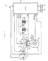
- FIG. 1 illustrates an exhaust gas purifying apparatus 1 to which the present invention is applied, together with an internal combustion engine (hereinafter called the "engine") 3.
- the engine 3 is, for example, a four-cylinder engine equipped in a vehicle, not shown.
- a combustion chamber 3c is formed between a piston 3a and a cylinder head 3b of the engine 3.
- An intake pipe 4 and an exhaust pipe 5 (exhaust system) are connected respectively to the cylinder head 3b, and a fuel injection valve (hereinafter called the "injector") 6 is attached to face the combustion chamber 3c.
- the injector 6 is disposed in a central region of the ceiling of the combustion chamber 3c, and is connected to a high-pressure pump and a fuel tank (none of which is shown) in order through a common rail. A fuel within the fuel tank is increased in pressure by the high-pressure pump, and then is sent to the injector 6 through the common rail for injection into the combustion chamber 3c from the injector 6.
- An injected fuel amount QINJ and an injection timing of the injector 6 are set by an ECU 2, and are controlled by driving signals from the ECU 2 to ensure the set injected fuel amount QINJ and injection timing.
- An engine water temperature sensor 29 is mounted on the body of the engine 3.
- the engine water temperature sensor 29 detects a temperature TW of cooling water (hereinafter called the "engine water temperature") which circulates within a cylinder block of the engine 3, and outputs its detection signal to the ECU 2.
- TW of cooling water hereinafter called the "engine water temperature”
- a magnet rotor 30a is attached to a crank shaft 3d of the engine 3, and a crank angle sensor 30 is made up of this magnet rotor 30a and an MRE pickup 30b.
- the crank angle sensor 30 outputs a CRK signal and a TDC signal, both of which are pulse signals, to the ECU 2 as the crank shaft 3d rotates.
- the CRK signal is outputted every predetermined crank angle (for example, every 30 °).
- the ECU 2 calculates the rotational speed of the engine 3 (hereinafter called the "engine rotational speed") NE based on the CRK signal.
- the TDC signal indicates that the piston 3a of each cylinder is at a predetermined crank angle position near the top dead center (TDC) at the start of an intake stroke, and is outputted every 180 ° of crank angle in the four-cylinder type of this example.
- a throttle valve (intake throttle valve) 7 is disposed at a position near the combustion chamber 3c in the intake pipe 4.
- An actuator 7a comprising a DC motor, for example, is connected to the throttle valve 7.
- An opening TH of the throttle valve 7 (hereinafter called the "throttle opening") is controlled by the ECU 2 which controls the duty ratio of a current supplied to the actuator 7a.
- the throttle opening TH is detected by a throttle opening sensor 31 which outputs its detection signal to the ECU 2.
- the intake pipe 4 is also provided with an air flow sensor 32 at a position upstream of the throttle valve 7 and an intake air temperature sensor 33 at a position downstream of the throttle valve 7.
- the air flow sensor 32 detects the amount QA of intake air, and outputs its detection signal to the ECU 2.
- the intake air temperature sensor 33 in turn detects the temperature TA of intake air (hereinafter called the "intake air temperature”), and outputs its detection signal to the ECU 2.
- the exhaust pipe 5 is provided with an oxidation catalyst 8 and a filter 9 in this order from the upstream side.
- the oxidation catalyst 8 oxidizes HC and CO within exhaust gases to purify the exhaust gases.
- the filter 9 collects particulate matters such as soot within exhaust gases to reduce the particulate matters emitted into the atmosphere.
- the filter 9 carries a catalyst (not shown) similar to the oxidation catalyst 8 on the surface thereof.
- the exhaust pipe 5 is further provided with a first exhaust gas temperature sensor 34 and a second exhaust gas temperature sensor 35 at positions immediately upstream of the oxidation catalyst 8 and immediately upstream of the filter 9, respectively.
- the first exhaust gas temperature sensor 34 detects the temperature TCATG of exhaust gases upstream of the oxidation catalyst 8 (hereinafter called the "pre-catalyst gas temperature”), and outputs its detection signal to the ECU 2.
- the second exhaust gas temperature sensor 35 detects the temperature TDPFG of exhaust gases upstream of the filter 9 (hereinafter called the "pre-filter gas temperature”), and outputs its detection signal to the ECU 2.
- the ECU 2 is further supplied with a detection signal indicative of an operation amount AP of an accelerator pedal (not shown) (hereinafter called the "accelerator opening") from an accelerator opening sensor 36, and a detection signal indicative of the atmospheric pressure PA from an atmospheric pressure sensor 37, respectively.
- the ECU 2 is based on a microcomputer which comprises an I/O interface, a CPU, a RAM, a ROM and the like.
- the detection signals from a variety of the aforementioned sensors 29 - 37 are applied to the CPU after they have undergone A/D conversion and waveform shaping.
- the CPU determines the operating condition of the engine 3 with reference to these signals applied thereto in accordance with a control program stored in the ROM, as well as executes a variety of control operations for the engine 3, including those for controlling the injected fuel amount QINJ of the injector 6 and the throttle opening TH, and executes a regeneration control process for regenerating the filter 9.
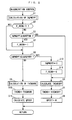
- Fig. 2 is a flow chart illustrating the regeneration control process. This process is executed in synchronism with the application of the TDC signal. It should be noted that the operation for regenerating the filter 9 in this process relies on the post-injection for injecting a fuel into the combustion chamber 3c in an expansion stroke or an exhaust stroke of the engine 3, thereby supplying an unburnt fuel into exhaust gases to burn particulate matters deposited in the filter 9, for purposes of regenerating the filter 9.
- step 1 labeleled as "S1" in the figure. The same designation applies to the following description
- SQPMDPF is calculated.
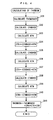
- This particulate matter amount integrated value SQPMDPF is an estimate of the amount of particulate matters deposited in the filter 9 at that time, and is calculated through a subroutine illustrated in Fig. 3.
- the amount QEX of particulate matters exhausted from the engine 3 is calculated per TDC, i.e. , one combustion at step 21.
- This calculation of the exhausted particulate matter amount QEX is made by searching an exhausted particulate matter amount map (not shown) in accordance with the engine rotational speed NE and injected fuel amount QINJ.
- the exhausted particulate matter amount map is created by finding the amount of particulate matters exhausted from the engine 3 in an experiment, and mapping the result of the experiment in accordance with the engine rotational speed NE and injected fuel amount QINJ.
- the injected fuel amount QINJ is determined by searching an injected fuel amount map (not shown) in accordance with the engine rotational speed NE and accelerator opening AP.
- a filter oxygen amount Q02DPF is calculated (step 22).
- This filter oxygen amount Q02DPF represents the amount of oxygen supplied to the filter 9, and is calculated from the injected fuel amount QINJ and intake air amount QA.
- a filter temperature TDPF is calculated (step 23). This filter temperature TDPF represents the temperature internal to the filter 9, and is calculated in accordance with the intake air amount QA, filter pre-gas temperature TDPFG and the like.
- a regenerated particulate matter amount QRN is calculated (step 24).
- This particulate matter amount QRN represents the amount of particulate matters which are burnt in the filter 9 for regeneration in a normal operation in which no regenerating operation is performed or in the regenerating operation.
- the regenerated particulate matter amount QRN is calculated by searching a map (not shown) in accordance with the filter oxygen amount Q02DPF and filter temperature TDPF found at the aforementioned steps 22, 23, respectively. In this map, the regenerated particulate matter amount QRN is set to a larger value as the filter oxygen amount Q02DPF is larger, or as the filter temperature TDPF is higher because of higher easiness of burning the particulate matters.
- a deposited particulate matter amount QPMDPF per TDC is calculated by subtracting the regenerated PM amount QRN from the exhausted particulate matter amount PME calculated at step 21 (step 25).
- the calculated deposited particulate matter amount QPMDPF is added to the deposited particulate matter amount integrated value SQPMDPF found up to the last time to calculate the currently deposited particulate matter amount integrated value SQPMDPF (step 26), followed by termination of the subroutine.
- the deposited particulate matter amount integrated value SQPMDPF is reset to zero when the filter 9 is regenerated.
- step 2 at step 2 subsequent to step 1, it is determined whether or not a regeneration execution flag F_REON is "1.” If the answer to step 2 is NO, indicating that the regenerating operation is not under way, it is determined whether or not the deposited particulate matter amount integrated value SQPMDPF calculated at step 1 is equal to or larger than a predetermined threshold value SQREFON (for example, nine grams) for determining the start of the regenerating operation (step 3). If the answer to step 3 is NO, indicating SQPMDPF ⁇ SQREFON, the flow proceeds to step 4 on the assumption that the regenerating operation is not performed because of a small amount of deposited particulate matters in the filter 9.
- a predetermined threshold value SQREFON for example, nine grams
- the calculated target opening THCMDOFF is set to a target opening THCMD for the throttle valve 7 (step 5).
- the target opening THCMD is set in this way, the duty ratio of a current supplied to the actuator 7a is controlled by the ECU 2 such that the throttle opening TH converges to the target opening THCMD.
- a post-injection amount QPOST is set to zero (step 6), followed by termination of this process.
- step 3 determines whether or not the deposited particulate matter amount integrated value SQPMDPF is equal to or smaller than a threshold value SQREFOFF for determining the end of the regenerating operation (step 8).
- This threshold value SQREFOFF is set to a predetermined value near zero.
- step 8 When the regenerating operation is started, the answer to step 8 is NO, causing the flow to proceed to step 9, where a target opening THCMDON is calculated for the throttle valve 7 during the regenerating operation. This calculation is made through a subroutine illustrated in Fig. 4.
- a basic value THCMDBASE is first calculated for the target opening THCMDON at step 31.
- This basic value THCMDBASE corresponds to a target opening to which the throttle valve 7 should be set at a normal temperature and a normal pressure, and is calculated by searching a basic value map (not shown) in accordance with the engine rotational speed NE and injected fuel amount QINJ.
- the basic value THCMDBASE is set to a smaller value than the target opening THCMDOFF during the non-regenerating operation calculated at the aforementioned step 4 in order to narrow down the throttle valve opening TH to decrease the intake air amount QA during the regenerating operation.
- an atmospheric pressure correction term CPA an intake air temperature correction term CTA, and a water temperature correction term CTW are calculated for use as correction terms for the basic value THCMDBASE.
- a basic value CPABASE is calculated for the atmospheric pressure correction term CPA.
- This basic value CPABASE determines a weight for the atmospheric pressure correction to the basic value THCMDBASE of the target opening THCMDON, and is calculated by searching a corresponding map (not shown) in accordance with the engine rotational speed NE and injected fuel amount QINJ.
- an atmospheric pressure correction coefficient KPA is calculated by searching an atmospheric pressure correction table of Fig. 5 in accordance with the atmospheric pressure PA (step 33).
- the atmospheric pressure correction coefficient KPA is set to a larger value as the atmospheric pressure PA is lower. This is intended to ensure the filter oxygen amount Q02DPF required for the regeneration of the filter 9 by compensating for a lower filter oxygen amount Q02DPF due to a lower density of intake air in a highland.
- the basic value CPABASE calculated at step 32 is multiplied by the calculated atmospheric pressure correction coefficient KPA to calculate the atmospheric pressure correction term CPA (step 34).
- a basic value CTABASE for the intake air temperature correction term CTA is calculated by searching a corresponding map (not shown) in accordance with the engine rotational speed NE and injected fuel amount QINJ.
- an intake air temperature correction coefficient KTA is calculated by searching an intake air temperature correction table of Fig. 6 in accordance with the intake air temperature TA (step 36).
- the intake air temperature correction coefficient KTA is set to a larger value as the intake air temperature TA is higher. This is intended to ensure the filter oxygen amount Q02DPF required for the regeneration of the filter 9 by compensating for a similarly lower density of the intake air as the intake air temperature is higher.
- the basic value CTABASE calculated at step 35 is multiplied by the calculated intake air temperature correction coefficient KTA to calculate the intake air temperature correction term CTA (step 37).
- a basic value CTWBASE for the water temperature correction term CTW is calculated by searching a corresponding map (not shown) in accordance with the engine rotational speed NE and injected fuel amount QINJ.
- awater temperature correction coefficient KTW is calculated by searching a water temperature correction table of Fig. 7 in accordance with the engine water temperature TW (step 39).
- the water temperature correction coefficient KTW is set to 1.0 when the engine water temperature TW is equal to or higher than a predetermined temperature TWO (for example, 60 ° C); to a value larger than 1. 0 when the engine water temperature is lower than the predetermined temperature TW; and to a larger value as the engine water temperature TW is lower.
- a predetermined temperature TWO for example, 60 ° C
- the engine is susceptible to an instable combustion state.
- an insufficient amount of intake air can be supplied to cause an instable combustion in the combustion chamber 3c, possibly resulting in misfire.
- the basic value CTWBASE calculated at step 38 is multiplied by the calculated water temperature correction coefficient KTW to calculate the water temperature correction term CTW (step 40).
- the atmospheric pressure correction term CPA, intake air temperature correction term CTA, and water temperature correction term CTW, calculated at steps 34, 37, 40, respectively, are added to the basic value THCMDBASE calculated at step 31 to calculate the target opening THCMDON for the regenerating operation (step 41), followed by termination of this subroutine.
- the target opening THCMDON for the regenerating operation is set to the target opening THCMD for the throttle valve 7.
- the post-injection amount QPOST is calculated (step 11), followed by termination of this process.
- the post-injection amount QPOST is calculated in accordance with a predetermined feedback control algorithm such that the filter pre-gas temperature TDPFG converges to a predetermined target temperature (for example, 600 °C). In this way, the filter 9 is regenerated by maintaining the filter 9 in a high-temperature state, and burning particulate matters deposited therein.
- step 8 if the answer to step 8 is YES, indicating that the deposited particulate matter amount integrated value SQPMDPF decreases to the threshold value SQREFOFF or less during the execution of the regenerating operation, the deposited particulate matter amount integrated value SQPMDPF is reset to zero on the assumption that the particulate matters deposited in the filter 9 have been sufficiently burnt so that the filter 9 has been regenerated (step 12). Also, the regeneration execution flag F_REON is set to "0" (step 13) to terminate the regenerating operation and execute the aforementioned steps 4 to 6.
- the target opening THCMD for the throttle valve 7 is set to the smaller target opening THCMDON for the regenerating operation to narrow down the throttle opening TH to reduce the intake air amount QA during the regenerating operation.
- the air/fuel ratio is controlled toward the richer side to increase the combustion temperature and exhaust gas temperature in the engine 3, thereby making it possible to stably burn particulate matters in the filter 9.
- the target opening THCMDON for the regenerating operation is corrected in accordance with the detected atmospheric pressure PA and intake air temperature TA, an amount of oxygen required to regenerate the filter 9 can be supplied neither too much nor too less, while compensating for the influence due to variations in density of intake air. As a result, a stable combustion of particulate matters can be ensured in the filter 9, to appropriately regenerate the filter 9. Further, since the target opening THCMDON for the regenerating operation is corrected to be a larger value as the detected engine water temperature TW is lower, a stable combustion can be ensured in the combustion chamber 3c, particularly, at low temperatures, while compensating for the influence due to the temperature of the internal combustion engine 3 to prevent misfire.
- the present invention is not limited to the embodiment described above, but can be practiced in a variety of manners.
- the target opening THCMDON for the throttle valve 7 during the regenerating operation is corrected in accordance with all of the engine water temperature TW, atmospheric pressure PA, and intake air temperature TA in the foregoing embodiment
- the target opening THCMDON may be corrected in accordance with arbitrary one or two of these parameters.
- the atmospheric pressure correction table, intake air temperature correction table, and water temperature correction table shown in Figs. 5 to 7 are illustrative in any way, and may be changed as appropriate in accordance with the characteristics and the like of the applied engine 3 and filter 9, as a matter of course.
- the water temperature correction table of Fig. 7 is set such that the water temperature correction coefficient KTW is larger as the engine water temperature TW is lower from a viewpoint of the stability of the combustion state in the engine at low temperatures
- the water temperature correction coefficient KTW can be set to a smaller value, conversely, in consideration of the influence on the exhaust gas temperature.
- the foregoing embodiment has employed the engine water temperature TW for a parameter indicative of the temperature of the internal combustion engine 3, an oil temperature of the engine 3 and the like may be used instead of or in addition to this.
- the unburnt fuel is supplied into exhaust gases through the post-injection into the combustion chamber 3c using the injector 6.
- a separate injector may be disposed at a position upstream of the oxidation catalyst 8 in the exhaust pipe 5 to directly inject the fuel into the exhaust pipe 5.
- the present invention is not limited to this particular engine, but can be applied to a variety of engines other than the diesel engine, including an engine for vessel propeller such as an outboard engine which has a crank shaft arranged in the vertical direction. Otherwise, details in the configuration may be modified as appropriate without departing from the spirit and scope of the present invention.
- An exhaust gas purifying apparatus and method for an internal combustion engine are provided for appropriately regenerating a filter by supplying neither too much nor too less intake air when the filter is regenerated by supplying an unburnt fuel into exhaust gases.
- a filter is disposed in the exhaust system for collecting particulate matters included in exhaust gases.
- An ECU instructs to burn particulate matters deposited in the filter to execute a regenerating operation for regenerating the filter.
- An intake throttle valve adjusts the amount of intake air flowing through an intake system of the internal combustion engine.
- the ECU controls the intake throttle valve to narrow down an opening of the intake throttle valve during execution of the regenerating operation by the regenerating operation executing means.
- the ECU also corrects the opening of the intake throttle valve in accordance with at least one of the temperature of the internal combustion engine, the atmospheric pressure, and the intake air temperature detected by at least one of sensors.
Landscapes
- Engineering & Computer Science (AREA)
- Chemical & Material Sciences (AREA)
- Combustion & Propulsion (AREA)
- Mechanical Engineering (AREA)
- General Engineering & Computer Science (AREA)
- Electrical Control Of Air Or Fuel Supplied To Internal-Combustion Engine (AREA)
- Processes For Solid Components From Exhaust (AREA)
- Filtering Of Dispersed Particles In Gases (AREA)
- Exhaust Gas Treatment By Means Of Catalyst (AREA)
- Exhaust Gas After Treatment (AREA)
Abstract
Description
- The present invention relates to an exhaust gas purifying apparatus and method for purifying exhaust gases by collecting particulate matters within the exhaust gases by a filter in a diesel engine and the like.
- An exhaust gas purifying apparatus for a diesel engine and the like, known in the past, comprises a filter in an exhaust system for collecting particulate matters within exhaust gases. Also, as conventionally known, Laid-open
Japanese Patent Application No. 9-287434 - The foregoing exhaust gas purifying apparatus comprises a regeneration unit for regenerating the filter. The regeneration unit comprises micro-wave supplying means for heating the filter to burn particulate matters; gas supplying means for supplying the filter with a gas including oxygen through a gas supply path; an ambient air introducing valve for introducing ambient air into the filter through the air supply path; a gas recirculation path for recirculating exhaust gases exhausted from the filter to the gas supply path; a bypass path for bypassing the filter; a variety of switching valves for switching these paths; and the like.
- When the filter is not regenerated, exhaust gases exhausted from the engine is passed through the filter by switching the paths by the switching valve to collect particulate matters within the exhaust gases in the filter. When the particulate matters deposited in the filter reach a predetermined amount, the exhaust gases are passed to the bypass path to bypass the filter, while the micro-wave supplying means is activated to heat the filter to burn the particulate matters deposited therein, thus regenerating the filter. During the regeneration, the burning of the particulate matters is promoted by supplying a gas to the filter by the gas supplying means with the gas supply path remaining opened, and opening the ambient air introducing valve to introduce ambient air into the filter. Also, the atmospheric temperature and atmospheric pressure are detected to correct the ambient air introducing valve for the opening in accordance with the detected temperature and pressure, to maintain a constant oxygen concentration of the gas supplied to the filter, thereby stably regenerating the filter.
- However, in this conventional exhaust gas purifying apparatus, the filter regeneration unit is exclusively used for regenerating the filter. This results in an extra space required for mounting the filter regeneration unit, a higher manufacturing cost, and a failure in application to an exhaust gas purifying apparatus of a type which regenerates a filter, for example, bypost-injection, i.e., by injecting a fuel into a combustion chamber in an expansion stroke and an exhaust stroke of the engine.
- Also, in this exhaust gas purifying apparatus, since the gas and ambient air for promoting the burning of particulate matters are directly supplied to the filter, the correction of the atmospheric air introducing valve for the opening in accordance with the atmospheric temperature and atmospheric pressure as mentioned above is effective for maintaining a constant oxygen concentration of the gas supplied to the filter to ensure stable regeneration of the filter. However, in a post-injection type regeneration unit, for example, intake air is not directly supplied to a filter but part thereof is burnt in a combustion camber together with a fuel before it is supplied to the filter. For this reason, even if an intake air amount is corrected using a conventional correction approach, both the combustion chamber and the filter cannot be appropriately supplied with required amounts of oxygen, possibly resulting in a failure of stably ensuring the combustion in the combustion chamber or the filter.
- The present invention has been made to solve the problem as mentioned above, and it is an object of the invention to provide an exhaust gas purifying apparatus and method for an internal combustion engine which are capable of appropriately regenerating a filter by supplying intake air, neither too much nor too less, when the filter is regenerated by supplying an unburnt fuel into exhaust gases.
- To achieve the above object according to a first aspect of the present invention, there is provided an exhaust gas purifying apparatus for an internal combustion engine for purifying exhaust gases by collecting particulate matters included in the exhaust gases emitted from the internal combustion engine to an exhaust system. The exhaust gas purifying apparatus is characterized by comprising a filter disposed in the exhaust system for collecting particulate matters included in exhaust gases; regenerating operation executing means for burning particulate matters deposited in the filter to execute a regenerating operation for regenerating the filter; an intake throttle valve for adjusting the amount of intake air flowing through an intake system of the internal combustion engine; intake air control means for controlling the intake throttle valve to narrow down an opening of the intake throttle valve during execution of the regenerating operation by the regenerating operation executing means; at least one of engine temperature detecting means for detecting a temperature of the internal combustion engine, atmospheric pressure detecting means for detecting the atmospheric pressure, and intake air temperature detecting means for detecting the temperature of intake are; and correcting means for correcting the opening of the intake throttle valve in accordance with at least one of the temperature of the internal combustion engine, the atmospheric pressure, and the intake air temperature detected by at least one of the detecting means.
- According to this exhaust gas purifying apparatus for an internal combustion engine, particulate matters in exhaust gases are collected by the filter. Also, the regenerating operation executing means executes the regenerating operation to supply an unburnt fuel into the exhaust gases and burn the articulate matters deposited in the filter, thereby regenerating the filter. Also, during the regenerating operation, the intake air control means controls the intake throttle valve to narrow down the opening thereof to reduce the intake air amount. Since the intake air amount is reduced by narrowing down the opening of the intake throttle valve during the regenerating operation, the air/fuel ratio can be controlled toward the richer side to increase the combustion temperature and exhaust gas temperature in the internal combustion engine to heat the filter, thereby stably burning the particulate matters in the filter.
- Also, at least one parameter of the temperature of the internal combustion engine, atmospheric pressure, and intake air temperature is detected to correct the opening of the intake throttle valve in accordance with the detected at least one parameter during the regenerating operation. The intake air varies in density between a flatland and a highland, or as the intake air varies in temperature. Therefore, by correcting the opening of the intake throttle valve in accordance with the detected atmosphere and/or temperature of intake air, an amount of oxygen required for regenerating the filter can be supplied neither too much nor too less, while compensating for the influence due to variations in density of intake air. As a result, a stable combustion of particulate matters can be ensured in the filter, to appropriately regenerate the filter. In addition, variations in the temperature of the internal combustion engine affect the temperature of exhaust gases and the combustion in the combustion chamber of the internal combustion engine as well. Accordingly, by correcting the opening of the intake throttle valve in accordance with the detected temperature of the internal combustion engine, a stable combustion can be ensured in the combustion chamber while compensating for the influence due to the temperature of the internal combustion engine.
- To achieve the above object, according to a second aspect of the present invention, there is provided a method of purifying exhaust gases in an internal combustion engine by collecting particulate matters included in the exhaust gases emitted from the internal combustion engine to an exhaust system. The method is characterized by comprising the steps of collecting particulate matters included in exhaust gases by a filter; burning particulate matters deposited in the filter to execute a regenerating operation for regenerating the filter; adjusting the amount of intake air flowing through an intake system of the internal combustion engine by an intake throttle valve; narrowing down an opening of the intake throttle valve during execution of a regenerating operation; detecting at least one of a temperature of the internal combustion engine, the atmospheric pressure, and the temperature of intake are; and correcting the opening of the intake throttle valve in accordance with at least one of the temperature of the internal combustion engine, the atmospheric pressure, and the intake air temperature.
- This method of purifying exhaust gases provides the same advantageous effects as described above concerning the exhaust gas purifying apparatus according to the first aspect of the invention.
- Preferably, in the exhaust gas purifying apparatus for an internal combustion engine described above, the at least one detecting means is the engine temperature detecting means, wherein the correcting means corrects the opening of the intake throttle valve to be larger as the temperature of the internal combustion engine is lower.
- According to this preferred embodiment of the exhaust gas purifying apparatus, since the opening of the intake throttle valve is corrected to be larger as the temperature of the internal combustion engine is lower during the regenerating operation, it is possible to prevent misfire during the regenerating operation without fail, while compensating for the influence of the temperature of the internal combustion engine, to ensure a stable combustion in the combustion chamber particularly at low temperatures.
- Preferably, in the method of purifying exhaust gases in an internal combustion engine described above, the step of detecting includes detecting the temperature of the internal combustion engine, wherein the step of correcting includes correcting the opening of the intake throttle valve to be larger as the temperature of the internal combustion engine is lower.
- This preferred embodiment of the method of purifying exhaust gases provides the same advantageous effects as described above concerning the exhaust gas purifying apparatus according to the first aspect of the invention.
-
- Fig. 1 is a diagram generally illustrating an exhaust gas purifying apparatus to which the present invention is applied, together with an internal combustion engine;
- Fig. 2 is a flow chart illustrating a filter regeneration control process;
- Fig. 3 is a flow chart illustrating a subroutine for calculating an integrated value of deposited particulate matter amount;
- Fig. 4 is a flow chart illustrating a subroutine for calculating a target opening for a throttle valve during a regenerating operation;
- Fig. 5 is an example of a table for calculating an atmospheric pressure correction coefficient;
- Fig. 6 is an example of a table for calculating an intake air temperature correction coefficient; and
- Fig. 7 is an example of a table for calculating a water temperature correction coefficient.
- In the following, a preferred embodiment of the present invention will be described in detail with reference to the accompanying drawings. Fig. 1 illustrates an exhaust gas purifying
apparatus 1 to which the present invention is applied, together with an internal combustion engine (hereinafter called the "engine") 3. Theengine 3 is, for example, a four-cylinder engine equipped in a vehicle, not shown. - A
combustion chamber 3c is formed between apiston 3a and acylinder head 3b of theengine 3. Anintake pipe 4 and an exhaust pipe 5 (exhaust system) are connected respectively to thecylinder head 3b, and a fuel injection valve (hereinafter called the "injector") 6 is attached to face thecombustion chamber 3c. - The
injector 6 is disposed in a central region of the ceiling of thecombustion chamber 3c, and is connected to a high-pressure pump and a fuel tank (none of which is shown) in order through a common rail. A fuel within the fuel tank is increased in pressure by the high-pressure pump, and then is sent to theinjector 6 through the common rail for injection into thecombustion chamber 3c from theinjector 6. An injected fuel amount QINJ and an injection timing of theinjector 6 are set by anECU 2, and are controlled by driving signals from theECU 2 to ensure the set injected fuel amount QINJ and injection timing. - An engine
water temperature sensor 29 is mounted on the body of theengine 3. The enginewater temperature sensor 29 detects a temperature TW of cooling water (hereinafter called the "engine water temperature") which circulates within a cylinder block of theengine 3, and outputs its detection signal to theECU 2. - A
magnet rotor 30a is attached to acrank shaft 3d of theengine 3, and acrank angle sensor 30 is made up of thismagnet rotor 30a and anMRE pickup 30b. Thecrank angle sensor 30 outputs a CRK signal and a TDC signal, both of which are pulse signals, to theECU 2 as thecrank shaft 3d rotates. The CRK signal is outputted every predetermined crank angle (for example, every 30 °). The ECU 2 calculates the rotational speed of the engine 3 (hereinafter called the "engine rotational speed") NE based on the CRK signal. The TDC signal indicates that thepiston 3a of each cylinder is at a predetermined crank angle position near the top dead center (TDC) at the start of an intake stroke, and is outputted every 180 ° of crank angle in the four-cylinder type of this example. - A throttle valve (intake throttle valve) 7 is disposed at a position near the
combustion chamber 3c in theintake pipe 4. An actuator 7a, comprising a DC motor, for example, is connected to thethrottle valve 7. An opening TH of the throttle valve 7 (hereinafter called the "throttle opening") is controlled by theECU 2 which controls the duty ratio of a current supplied to the actuator 7a. The throttle opening TH is detected by athrottle opening sensor 31 which outputs its detection signal to theECU 2. - The
intake pipe 4 is also provided with anair flow sensor 32 at a position upstream of thethrottle valve 7 and an intakeair temperature sensor 33 at a position downstream of thethrottle valve 7. Theair flow sensor 32 detects the amount QA of intake air, and outputs its detection signal to theECU 2. The intakeair temperature sensor 33 in turn detects the temperature TA of intake air (hereinafter called the "intake air temperature"), and outputs its detection signal to theECU 2. - The
exhaust pipe 5 is provided with anoxidation catalyst 8 and afilter 9 in this order from the upstream side. Theoxidation catalyst 8 oxidizes HC and CO within exhaust gases to purify the exhaust gases. Thefilter 9 collects particulate matters such as soot within exhaust gases to reduce the particulate matters emitted into the atmosphere. Thefilter 9 carries a catalyst (not shown) similar to theoxidation catalyst 8 on the surface thereof. - The
exhaust pipe 5 is further provided with a first exhaustgas temperature sensor 34 and a second exhaustgas temperature sensor 35 at positions immediately upstream of theoxidation catalyst 8 and immediately upstream of thefilter 9, respectively. The first exhaustgas temperature sensor 34 detects the temperature TCATG of exhaust gases upstream of the oxidation catalyst 8 (hereinafter called the "pre-catalyst gas temperature"), and outputs its detection signal to theECU 2. The second exhaustgas temperature sensor 35 detects the temperature TDPFG of exhaust gases upstream of the filter 9 (hereinafter called the "pre-filter gas temperature"), and outputs its detection signal to theECU 2. - The
ECU 2 is further supplied with a detection signal indicative of an operation amount AP of an accelerator pedal (not shown) (hereinafter called the "accelerator opening") from anaccelerator opening sensor 36, and a detection signal indicative of the atmospheric pressure PA from anatmospheric pressure sensor 37, respectively. - The
ECU 2 is based on a microcomputer which comprises an I/O interface, a CPU, a RAM, a ROM and the like. - The detection signals from a variety of the aforementioned sensors 29 - 37 are applied to the CPU after they have undergone A/D conversion and waveform shaping. The CPU determines the operating condition of the
engine 3 with reference to these signals applied thereto in accordance with a control program stored in the ROM, as well as executes a variety of control operations for theengine 3, including those for controlling the injected fuel amount QINJ of theinjector 6 and the throttle opening TH, and executes a regeneration control process for regenerating thefilter 9. - Fig. 2 is a flow chart illustrating the regeneration control process. This process is executed in synchronism with the application of the TDC signal. It should be noted that the operation for regenerating the
filter 9 in this process relies on the post-injection for injecting a fuel into thecombustion chamber 3c in an expansion stroke or an exhaust stroke of theengine 3, thereby supplying an unburnt fuel into exhaust gases to burn particulate matters deposited in thefilter 9, for purposes of regenerating thefilter 9. In this process, first at step 1 (labeled as "S1" in the figure. The same designation applies to the following description), a deposited particulate matter amount integrated value SQPMDPF is calculated. This particulate matter amount integrated value SQPMDPF is an estimate of the amount of particulate matters deposited in thefilter 9 at that time, and is calculated through a subroutine illustrated in Fig. 3. - Referring now to Fig. 3, the amount QEX of particulate matters exhausted from the
engine 3 is calculated per TDC, i.e. , one combustion at step 21. This calculation of the exhausted particulate matter amount QEX is made by searching an exhausted particulate matter amount map (not shown) in accordance with the engine rotational speed NE and injected fuel amount QINJ. The exhausted particulate matter amount map is created by finding the amount of particulate matters exhausted from theengine 3 in an experiment, and mapping the result of the experiment in accordance with the engine rotational speed NE and injected fuel amount QINJ. The injected fuel amount QINJ is determined by searching an injected fuel amount map (not shown) in accordance with the engine rotational speed NE and accelerator opening AP. - Next, a filter oxygen amount Q02DPF is calculated (step 22). This filter oxygen amount Q02DPF represents the amount of oxygen supplied to the
filter 9, and is calculated from the injected fuel amount QINJ and intake air amount QA. Also, a filter temperature TDPF is calculated (step 23). This filter temperature TDPF represents the temperature internal to thefilter 9, and is calculated in accordance with the intake air amount QA, filter pre-gas temperature TDPFG and the like. - Next, a regenerated particulate matter amount QRN is calculated (step 24). This particulate matter amount QRN represents the amount of particulate matters which are burnt in the
filter 9 for regeneration in a normal operation in which no regenerating operation is performed or in the regenerating operation. The regenerated particulate matter amount QRN is calculated by searching a map (not shown) in accordance with the filter oxygen amount Q02DPF and filter temperature TDPF found at the aforementioned steps 22, 23, respectively. In this map, the regenerated particulate matter amount QRN is set to a larger value as the filter oxygen amount Q02DPF is larger, or as the filter temperature TDPF is higher because of higher easiness of burning the particulate matters. - Next, a deposited particulate matter amount QPMDPF per TDC is calculated by subtracting the regenerated PM amount QRN from the exhausted particulate matter amount PME calculated at step 21 (step 25). Next, the calculated deposited particulate matter amount QPMDPF is added to the deposited particulate matter amount integrated value SQPMDPF found up to the last time to calculate the currently deposited particulate matter amount integrated value SQPMDPF (step 26), followed by termination of the subroutine. As will be later described, the deposited particulate matter amount integrated value SQPMDPF is reset to zero when the
filter 9 is regenerated. - Turning back to Fig. 2, at
step 2 subsequent to step 1, it is determined whether or not a regeneration execution flag F_REON is "1." If the answer to step 2 is NO, indicating that the regenerating operation is not under way, it is determined whether or not the deposited particulate matter amount integrated value SQPMDPF calculated atstep 1 is equal to or larger than a predetermined threshold value SQREFON (for example, nine grams) for determining the start of the regenerating operation (step 3). If the answer to step 3 is NO, indicating SQPMDPF<SQREFON, the flow proceeds to step 4 on the assumption that the regenerating operation is not performed because of a small amount of deposited particulate matters in thefilter 9. - At
step 4, a target opening THCMDOFF of thethrottle valve 7 during a non-regenerating operation in accordance with the engine rotational speed NE and intake air amount QINJ. Next, the calculated target opening THCMDOFF is set to a target opening THCMD for the throttle valve 7 (step 5). When the target opening THCMD is set in this way, the duty ratio of a current supplied to the actuator 7a is controlled by theECU 2 such that the throttle opening TH converges to the target opening THCMD. Next, a post-injection amount QPOST is set to zero (step 6), followed by termination of this process. - On the other hand, if the answer to step 3 is YES, indicating that the deposited particulate matter amount integrated value SQPMDPF reaches the threshold value SQREFON, the regeneration execution flag F_REON is set to "1" on the assumption that the regenerating operation will be started (step 7). Next, it is determined whether or not the deposited particulate matter amount integrated value SQPMDPF is equal to or smaller than a threshold value SQREFOFF for determining the end of the regenerating operation (step 8). This threshold value SQREFOFF is set to a predetermined value near zero.
- When the regenerating operation is started, the answer to step 8 is NO, causing the flow to proceed to step 9, where a target opening THCMDON is calculated for the
throttle valve 7 during the regenerating operation. This calculation is made through a subroutine illustrated in Fig. 4. - Referring now to Fig. 4, a basic value THCMDBASE is first calculated for the target opening THCMDON at
step 31. This basic value THCMDBASE corresponds to a target opening to which thethrottle valve 7 should be set at a normal temperature and a normal pressure, and is calculated by searching a basic value map (not shown) in accordance with the engine rotational speed NE and injected fuel amount QINJ. In this basic value map, the basic value THCMDBASE is set to a smaller value than the target opening THCMDOFF during the non-regenerating operation calculated at theaforementioned step 4 in order to narrow down the throttle valve opening TH to decrease the intake air amount QA during the regenerating operation. - Then, at steps 32 - 40, an atmospheric pressure correction term CPA, an intake air temperature correction term CTA, and a water temperature correction term CTW are calculated for use as correction terms for the basic value THCMDBASE.
- First at
step 32, a basic value CPABASE is calculated for the atmospheric pressure correction term CPA. This basic value CPABASE determines a weight for the atmospheric pressure correction to the basic value THCMDBASE of the target opening THCMDON, and is calculated by searching a corresponding map (not shown) in accordance with the engine rotational speed NE and injected fuel amount QINJ. - Next, an atmospheric pressure correction coefficient KPA is calculated by searching an atmospheric pressure correction table of Fig. 5 in accordance with the atmospheric pressure PA (step 33). In this atmospheric pressure correction table, the atmospheric pressure correction coefficient KPA is set to a larger value as the atmospheric pressure PA is lower. This is intended to ensure the filter oxygen amount Q02DPF required for the regeneration of the
filter 9 by compensating for a lower filter oxygen amount Q02DPF due to a lower density of intake air in a highland. Next, the basic value CPABASE calculated atstep 32 is multiplied by the calculated atmospheric pressure correction coefficient KPA to calculate the atmospheric pressure correction term CPA (step 34). - Likewise, at
step 35, a basic value CTABASE for the intake air temperature correction term CTA is calculated by searching a corresponding map (not shown) in accordance with the engine rotational speed NE and injected fuel amount QINJ. Next, an intake air temperature correction coefficient KTA is calculated by searching an intake air temperature correction table of Fig. 6 in accordance with the intake air temperature TA (step 36). In this intake air temperature correction table, the intake air temperature correction coefficient KTA is set to a larger value as the intake air temperature TA is higher. This is intended to ensure the filter oxygen amount Q02DPF required for the regeneration of thefilter 9 by compensating for a similarly lower density of the intake air as the intake air temperature is higher. Next, the basic value CTABASE calculated atstep 35 is multiplied by the calculated intake air temperature correction coefficient KTA to calculate the intake air temperature correction term CTA (step 37). - Next, at step 38, a basic value CTWBASE for the water temperature correction term CTW is calculated by searching a corresponding map (not shown) in accordance with the engine rotational speed NE and injected fuel amount QINJ. Next, awater temperature correction coefficient KTW is calculated by searching a water temperature correction table of Fig. 7 in accordance with the engine water temperature TW (step 39).
- In this water temperature correction table, the water temperature correction coefficient KTW is set to 1.0 when the engine water temperature TW is equal to or higher than a predetermined temperature TWO (for example, 60 ° C); to a value larger than 1. 0 when the engine water temperature is lower than the predetermined temperature TW; and to a larger value as the engine water temperature TW is lower. As the temperature of the
engine 3 is lower, the engine is susceptible to an instable combustion state.
Particularly, when the throttle valve opening TA is narrowed down for the regenerating operation, an insufficient amount of intake air can be supplied to cause an instable combustion in thecombustion chamber 3c, possibly resulting in misfire. Therefore, by setting the water temperature correction coefficient KTW to a larger value as the engine water temperature TW is lower to increase the intake air amount QA, it is possible to prevent the misfire during the regenerating operation without fail to ensure a stable combustion in thecombustion chamber 3c. - Next, the basic value CTWBASE calculated at step 38 is multiplied by the calculated water temperature correction coefficient KTW to calculate the water temperature correction term CTW (step 40).
- Next, the atmospheric pressure correction term CPA, intake air temperature correction term CTA, and water temperature correction term CTW, calculated at
steps step 31 to calculate the target opening THCMDON for the regenerating operation (step 41), followed by termination of this subroutine. - Turning back to Fig. 2, at
step 10 subsequent to step 9, the target opening THCMDON for the regenerating operation, calculated as described above, is set to the target opening THCMD for thethrottle valve 7. Next, the post-injection amount QPOST is calculated (step 11), followed by termination of this process. The post-injection amount QPOST is calculated in accordance with a predetermined feedback control algorithm such that the filter pre-gas temperature TDPFG converges to a predetermined target temperature (for example, 600 °C). In this way, thefilter 9 is regenerated by maintaining thefilter 9 in a high-temperature state, and burning particulate matters deposited therein. - On the other hand, if the answer to step 8 is YES, indicating that the deposited particulate matter amount integrated value SQPMDPF decreases to the threshold value SQREFOFF or less during the execution of the regenerating operation, the deposited particulate matter amount integrated value SQPMDPF is reset to zero on the assumption that the particulate matters deposited in the
filter 9 have been sufficiently burnt so that thefilter 9 has been regenerated (step 12). Also, the regeneration execution flag F_REON is set to "0" (step 13) to terminate the regenerating operation and execute theaforementioned steps 4 to 6. - As described above, according to this embodiment, the target opening THCMD for the
throttle valve 7 is set to the smaller target opening THCMDON for the regenerating operation to narrow down the throttle opening TH to reduce the intake air amount QA during the regenerating operation. In this way, the air/fuel ratio is controlled toward the richer side to increase the combustion temperature and exhaust gas temperature in theengine 3, thereby making it possible to stably burn particulate matters in thefilter 9. - Also, since the target opening THCMDON for the regenerating operation is corrected in accordance with the detected atmospheric pressure PA and intake air temperature TA, an amount of oxygen required to regenerate the
filter 9 can be supplied neither too much nor too less, while compensating for the influence due to variations in density of intake air. As a result, a stable combustion of particulate matters can be ensured in thefilter 9, to appropriately regenerate thefilter 9. Further, since the target opening THCMDON for the regenerating operation is corrected to be a larger value as the detected engine water temperature TW is lower, a stable combustion can be ensured in thecombustion chamber 3c, particularly, at low temperatures, while compensating for the influence due to the temperature of theinternal combustion engine 3 to prevent misfire. - It should be understood that the present invention is not limited to the embodiment described above, but can be practiced in a variety of manners. For example, while the target opening THCMDON for the
throttle valve 7 during the regenerating operation is corrected in accordance with all of the engine water temperature TW, atmospheric pressure PA, and intake air temperature TA in the foregoing embodiment, the target opening THCMDON may be corrected in accordance with arbitrary one or two of these parameters. - The atmospheric pressure correction table, intake air temperature correction table, and water temperature correction table shown in Figs. 5 to 7 are illustrative in any way, and may be changed as appropriate in accordance with the characteristics and the like of the applied
engine 3 andfilter 9, as a matter of course. For example, while the water temperature correction table of Fig. 7 is set such that the water temperature correction coefficient KTW is larger as the engine water temperature TW is lower from a viewpoint of the stability of the combustion state in the engine at low temperatures, the water temperature correction coefficient KTW can be set to a smaller value, conversely, in consideration of the influence on the exhaust gas temperature. Further, while the foregoing embodiment has employed the engine water temperature TW for a parameter indicative of the temperature of theinternal combustion engine 3, an oil temperature of theengine 3 and the like may be used instead of or in addition to this. - Also, in the foregoing embodiment, the unburnt fuel is supplied into exhaust gases through the post-injection into the
combustion chamber 3c using theinjector 6. Alternatively, a separate injector may be disposed at a position upstream of theoxidation catalyst 8 in theexhaust pipe 5 to directly inject the fuel into theexhaust pipe 5. - Further, wile the foregoing embodiment has shown an example in which the present invention is applied to a diesel engine, the present invention is not limited to this particular engine, but can be applied to a variety of engines other than the diesel engine, including an engine for vessel propeller such as an outboard engine which has a crank shaft arranged in the vertical direction. Otherwise, details in the configuration may be modified as appropriate without departing from the spirit and scope of the present invention.
- An exhaust gas purifying apparatus and method for an internal combustion engine are provided for appropriately regenerating a filter by supplying neither too much nor too less intake air when the filter is regenerated by supplying an unburnt fuel into exhaust gases. A filter is disposed in the exhaust system for collecting particulate matters included in exhaust gases. An ECU instructs to burn particulate matters deposited in the filter to execute a regenerating operation for regenerating the filter. An intake throttle valve adjusts the amount of intake air flowing through an intake system of the internal combustion engine. The ECU controls the intake throttle valve to narrow down an opening of the intake throttle valve during execution of the regenerating operation by the regenerating operation executing means. The ECU also corrects the opening of the intake throttle valve in accordance with at least one of the temperature of the internal combustion engine, the atmospheric pressure, and the intake air temperature detected by at least one of sensors.
Claims (4)
- An exhaust gas purifying apparatus for an internal combustion engine for purifying exhaust gases by collecting particulate matters included in the exhaust gases emitted from said internal combustion engine to an exhaust system, said exhaust gas purifying apparatus comprising:a filter disposed in said exhaust system for collecting particulate matters included in exhaust gases;regenerating operation executing means for burning particulate matters deposited in said filter to execute a regenerating operation for regenerating said filter;an intake throttle valve for adjusting the amount of intake air flowing through an intake system of said internal combustion engine;intake air control means for controlling said intake throttle valve to narrow down an opening of said intake throttle valve during execution of the regenerating operation by said regenerating operation executing means;at least one of engine temperature detecting means for detecting a temperature of said internal combustion engine, atmospheric pressure detecting means for detecting the atmospheric pressure, and intake air temperature detecting means for detecting the temperature of intake are; andcorrecting means for correcting the opening of said intake throttle valve in accordance with at least one of the temperature of said internal combustion engine, the atmospheric pressure, and the intake air temperature detected by at least one of said detecting means.
- An exhaust gas purifying apparatus for an internal combustion engine according to claim 1, wherein:said at least one detecting means is said engine temperature detecting means,wherein said correcting means corrects the opening of said intake throttle valve to be larger as the temperature of said internal combustion engine is lower.
- A method of purifying exhaust gases in an internal combustion engine by collecting particulate matters included in the exhaust gases emitted from said internal combustion engine to an exhaust system, said method comprising the steps of:collecting particulate matters included in exhaust gases by a filter;burning particulate matters deposited in said filter to execute a regenerating operation for regenerating said filter;adjusting the amount of intake air flowing through an intake system of said internal combustion engine by an intake throttle valve;narrowing down an opening of said intake throttle valve during execution of a regenerating operation;detecting at least one of a temperature of said internal combustion engine, the atmospheric pressure, and the temperature of intake are; andcorrecting the opening of said intake throttle valve in accordance with at least one of the temperature of said internal combustion engine, the atmospheric pressure, and the intake air temperature.
- A method of purifying exhaust gases in an internal combustion engine according to claim 3, wherein:said step of detecting includes detecting the temperature of said internal combustion engine,wherein said step of correcting includes correcting the opening of said intake throttle valve to be larger as the temperature of said internal combustion engine is lower.
Applications Claiming Priority (1)
| Application Number | Priority Date | Filing Date | Title |
|---|---|---|---|
| JP2005141624A JP4463144B2 (en) | 2005-05-13 | 2005-05-13 | Exhaust gas purification device for internal combustion engine |
Publications (2)
| Publication Number | Publication Date |
|---|---|
| EP1726806A1 true EP1726806A1 (en) | 2006-11-29 |
| EP1726806B1 EP1726806B1 (en) | 2010-03-17 |
Family
ID=36809639
Family Applications (1)
| Application Number | Title | Priority Date | Filing Date |
|---|---|---|---|
| EP06009461A Expired - Lifetime EP1726806B1 (en) | 2005-05-13 | 2006-05-08 | Particle filter regeneration apparatus and method for internal combustion engine |
Country Status (4)
| Country | Link |
|---|---|
| US (1) | US20060254261A1 (en) |
| EP (1) | EP1726806B1 (en) |
| JP (1) | JP4463144B2 (en) |
| DE (1) | DE602006012898D1 (en) |
Cited By (3)
| Publication number | Priority date | Publication date | Assignee | Title |
|---|---|---|---|---|
| CN103485909A (en) * | 2012-06-13 | 2014-01-01 | 福特环球技术公司 | System and method for compensating gaseous fuel injection |
| WO2015023350A1 (en) * | 2013-08-14 | 2015-02-19 | Carrier Corporation | Diesel engine powered transportation refrigeration system |
| US11053834B2 (en) | 2015-09-29 | 2021-07-06 | Carrier Corporation | Transportation refrigeration system comprising a refrigeration unit and a diesel engine |
Families Citing this family (7)
| Publication number | Priority date | Publication date | Assignee | Title |
|---|---|---|---|---|
| DE102007010189A1 (en) * | 2007-03-02 | 2008-09-04 | Robert Bosch Gmbh | Particle-filter method for controlling regeneration of a particle filter in an internal combustion engine's exhaust gas system controls burn-up of particles in a particle filter |
| US8146349B2 (en) * | 2008-03-31 | 2012-04-03 | Caterpiller Inc. | Exhaust system implementing temperature-constraining regeneration strategy |
| JP5682159B2 (en) * | 2010-06-30 | 2015-03-11 | マツダ株式会社 | diesel engine |
| JP5673356B2 (en) * | 2011-05-27 | 2015-02-18 | 株式会社デンソー | Control device for internal combustion engine |
| JP2013068186A (en) * | 2011-09-26 | 2013-04-18 | Kubota Corp | Diesel engine |
| JP5986736B2 (en) | 2011-11-16 | 2016-09-06 | 三菱重工業株式会社 | Exhaust gas purification system for internal combustion engine |
| CN114396343A (en) * | 2022-01-26 | 2022-04-26 | 湖南道依茨动力有限公司 | Engine air inflow control method and device, engine and engineering equipment |
Citations (5)
| Publication number | Priority date | Publication date | Assignee | Title |
|---|---|---|---|---|
| JPH09287434A (en) * | 1996-04-25 | 1997-11-04 | Matsushita Electric Ind Co Ltd | Filter regeneration device |
| US20040206070A1 (en) * | 2003-04-18 | 2004-10-21 | Nissan Motor Co., Ltd. | Exhaust gas purifying system for internal combustion engine |
| EP1517029A2 (en) * | 2003-09-17 | 2005-03-23 | Nissan Motor Co., Ltd. | Regeneration control of diesel particulate filter |
| EP1577524A2 (en) * | 2004-03-17 | 2005-09-21 | Nissan Motor Co., Ltd. | Regeneration of diesel particulate filter |
| EP1584805A2 (en) * | 2004-04-09 | 2005-10-12 | Isuzu Motors Limited | Engine exhaust gas purification device |
Family Cites Families (8)
| Publication number | Priority date | Publication date | Assignee | Title |
|---|---|---|---|---|
| US4756155A (en) * | 1985-03-26 | 1988-07-12 | Nissan Motor Company, Ltd. | Exhaust particle removing system for an internal combustion engine |
| JPH02104930A (en) * | 1988-10-13 | 1990-04-17 | Fuji Heavy Ind Ltd | Device for controlling fuel injection of internal combustion engine |
| US6490857B2 (en) * | 2000-06-29 | 2002-12-10 | Toyota Jidosha Kabushiki Kaisha | Device for purifying the exhaust gas of an internal combustion engine |
| JP2004100516A (en) * | 2002-09-06 | 2004-04-02 | Mitsubishi Fuso Truck & Bus Corp | Failure detector of internal combustion engine |
| JP2004176663A (en) * | 2002-11-28 | 2004-06-24 | Honda Motor Co Ltd | Exhaust purification device for internal combustion engine |
| US6931842B2 (en) * | 2002-11-29 | 2005-08-23 | Nissan Motor Co., Ltd. | Regeneration of diesel particulate filter |
| JP2005042661A (en) * | 2003-07-25 | 2005-02-17 | Nissan Motor Co Ltd | Combustion control device for internal combustion engine |
| JP4075755B2 (en) * | 2003-09-22 | 2008-04-16 | トヨタ自動車株式会社 | Method for suppressing filter overheating of internal combustion engine |
-
2005
- 2005-05-13 JP JP2005141624A patent/JP4463144B2/en not_active Expired - Fee Related
-
2006
- 2006-05-08 EP EP06009461A patent/EP1726806B1/en not_active Expired - Lifetime
- 2006-05-08 DE DE602006012898T patent/DE602006012898D1/en not_active Expired - Lifetime
- 2006-05-11 US US11/431,881 patent/US20060254261A1/en not_active Abandoned
Patent Citations (5)
| Publication number | Priority date | Publication date | Assignee | Title |
|---|---|---|---|---|
| JPH09287434A (en) * | 1996-04-25 | 1997-11-04 | Matsushita Electric Ind Co Ltd | Filter regeneration device |
| US20040206070A1 (en) * | 2003-04-18 | 2004-10-21 | Nissan Motor Co., Ltd. | Exhaust gas purifying system for internal combustion engine |
| EP1517029A2 (en) * | 2003-09-17 | 2005-03-23 | Nissan Motor Co., Ltd. | Regeneration control of diesel particulate filter |
| EP1577524A2 (en) * | 2004-03-17 | 2005-09-21 | Nissan Motor Co., Ltd. | Regeneration of diesel particulate filter |
| EP1584805A2 (en) * | 2004-04-09 | 2005-10-12 | Isuzu Motors Limited | Engine exhaust gas purification device |
Non-Patent Citations (1)
| Title |
|---|
| PATENT ABSTRACTS OF JAPAN vol. 1998, no. 03 27 February 1998 (1998-02-27) * |
Cited By (5)
| Publication number | Priority date | Publication date | Assignee | Title |
|---|---|---|---|---|
| CN103485909A (en) * | 2012-06-13 | 2014-01-01 | 福特环球技术公司 | System and method for compensating gaseous fuel injection |
| CN103485909B (en) * | 2012-06-13 | 2017-08-11 | 福特环球技术公司 | System and method for compensation gas fuel injection |
| WO2015023350A1 (en) * | 2013-08-14 | 2015-02-19 | Carrier Corporation | Diesel engine powered transportation refrigeration system |
| US9884539B2 (en) | 2013-08-14 | 2018-02-06 | Carrier Corporation | Diesel engine powered transportation refrigeration system |
| US11053834B2 (en) | 2015-09-29 | 2021-07-06 | Carrier Corporation | Transportation refrigeration system comprising a refrigeration unit and a diesel engine |
Also Published As
| Publication number | Publication date |
|---|---|
| JP4463144B2 (en) | 2010-05-12 |
| EP1726806B1 (en) | 2010-03-17 |
| US20060254261A1 (en) | 2006-11-16 |
| JP2006316735A (en) | 2006-11-24 |
| DE602006012898D1 (en) | 2010-04-29 |
Similar Documents
| Publication | Publication Date | Title |
|---|---|---|
| EP1959110B1 (en) | Exhaust emission control device and method for internal combustion engine | |
| US8141349B2 (en) | Exhaust emission control device and method for internal combustion engine, and engine control unit | |
| US7930879B2 (en) | Control device for internal combustion engine | |
| EP1725750A1 (en) | Regeneration controller for exhaust purification apparatus of internal combustion engine | |
| EP1965060B1 (en) | Exhaust emission control device and method for internal combustion engine | |
| US7849677B2 (en) | Regeneration controller for exhaust purification apparatus of internal combustion engine | |
| US7331171B2 (en) | Control system and method for internal combustion engine | |
| US7677029B2 (en) | Regeneration controller for exhaust purification apparatus of internal combustion engine | |
| EP1865165B1 (en) | Exhaust emission control system for internal combustion engine and control method therefor | |
| EP1726806B1 (en) | Particle filter regeneration apparatus and method for internal combustion engine | |
| US8117829B2 (en) | Exhaust emission control device and method for internal combustion engine, and engine control unit | |
| JP2006316746A (en) | Exhaust gas purification device for internal combustion engine | |
| US7997067B2 (en) | Exhaust emission control device and method for internal combustion engine, and engine control unit | |
| EP2175122A2 (en) | Exhaust gas purification system for internal combustion engine | |
| JP4447510B2 (en) | Exhaust gas purification device for internal combustion engine | |
| US7493755B2 (en) | System for assisting the regeneration of depollution means for a motor vehicle engine | |
| JP2008144726A (en) | Exhaust gas purification device for internal combustion engine | |
| JP4512519B2 (en) | Exhaust gas purification device for internal combustion engine | |
| JP2011012599A (en) | Exhaust emission control device for internal combustion engine | |
| JP2006316734A (en) | Exhaust gas purification device for internal combustion engine | |
| JP2010265803A (en) | Control device for internal combustion engine |
Legal Events
| Date | Code | Title | Description |
|---|---|---|---|
| PUAI | Public reference made under article 153(3) epc to a published international application that has entered the european phase |
Free format text: ORIGINAL CODE: 0009012 |
|
| AK | Designated contracting states |
Kind code of ref document: A1 Designated state(s): AT BE BG CH CY CZ DE DK EE ES FI FR GB GR HU IE IS IT LI LT LU LV MC NL PL PT RO SE SI SK TR |
|
| AX | Request for extension of the european patent |
Extension state: AL BA HR MK YU |
|
| 17P | Request for examination filed |
Effective date: 20061024 |
|
| 17Q | First examination report despatched |
Effective date: 20070111 |
|
| AKX | Designation fees paid |
Designated state(s): DE FR GB |
|
| GRAP | Despatch of communication of intention to grant a patent |
Free format text: ORIGINAL CODE: EPIDOSNIGR1 |
|
| RAP1 | Party data changed (applicant data changed or rights of an application transferred) |
Owner name: HONDA MOTOR CO., LTD. |
|
| GRAS | Grant fee paid |
Free format text: ORIGINAL CODE: EPIDOSNIGR3 |
|
| GRAA | (expected) grant |
Free format text: ORIGINAL CODE: 0009210 |
|
| AK | Designated contracting states |
Kind code of ref document: B1 Designated state(s): DE FR GB |
|
| REG | Reference to a national code |
Ref country code: GB Ref legal event code: FG4D |
|
| REF | Corresponds to: |
Ref document number: 602006012898 Country of ref document: DE Date of ref document: 20100429 Kind code of ref document: P |
|
| PLBE | No opposition filed within time limit |
Free format text: ORIGINAL CODE: 0009261 |
|
| STAA | Information on the status of an ep patent application or granted ep patent |
Free format text: STATUS: NO OPPOSITION FILED WITHIN TIME LIMIT |
|
| 26N | No opposition filed |
Effective date: 20101220 |
|
| GBPC | Gb: european patent ceased through non-payment of renewal fee |
Effective date: 20100617 |
|
| PG25 | Lapsed in a contracting state [announced via postgrant information from national office to epo] |
Ref country code: GB Free format text: LAPSE BECAUSE OF NON-PAYMENT OF DUE FEES Effective date: 20100617 |
|
| PGFP | Annual fee paid to national office [announced via postgrant information from national office to epo] |
Ref country code: FR Payment date: 20120608 Year of fee payment: 7 |
|
| REG | Reference to a national code |
Ref country code: FR Ref legal event code: ST Effective date: 20140131 |
|
| REG | Reference to a national code |
Ref country code: DE Ref legal event code: R084 Ref document number: 602006012898 Country of ref document: DE Effective date: 20140204 |
|
| PG25 | Lapsed in a contracting state [announced via postgrant information from national office to epo] |
Ref country code: FR Free format text: LAPSE BECAUSE OF NON-PAYMENT OF DUE FEES Effective date: 20130531 |
|
| PGFP | Annual fee paid to national office [announced via postgrant information from national office to epo] |
Ref country code: DE Payment date: 20160504 Year of fee payment: 11 |
|
| REG | Reference to a national code |
Ref country code: DE Ref legal event code: R119 Ref document number: 602006012898 Country of ref document: DE |
|
| PG25 | Lapsed in a contracting state [announced via postgrant information from national office to epo] |
Ref country code: DE Free format text: LAPSE BECAUSE OF NON-PAYMENT OF DUE FEES Effective date: 20171201 |