EP1726792A2 - Valve drive mechanism for engine - Google Patents
Valve drive mechanism for engine Download PDFInfo
- Publication number
- EP1726792A2 EP1726792A2 EP20060010741 EP06010741A EP1726792A2 EP 1726792 A2 EP1726792 A2 EP 1726792A2 EP 20060010741 EP20060010741 EP 20060010741 EP 06010741 A EP06010741 A EP 06010741A EP 1726792 A2 EP1726792 A2 EP 1726792A2
- Authority
- EP
- European Patent Office
- Prior art keywords
- valve
- rocker
- exhaust
- sub
- cam
- Prior art date
- Legal status (The legal status is an assumption and is not a legal conclusion. Google has not performed a legal analysis and makes no representation as to the accuracy of the status listed.)
- Withdrawn
Links
- 230000007246 mechanism Effects 0.000 title claims abstract description 130
- 230000006835 compression Effects 0.000 claims abstract description 62
- 238000007906 compression Methods 0.000 claims abstract description 62
- 239000000203 mixture Substances 0.000 claims abstract description 34
- 239000007789 gas Substances 0.000 claims abstract description 25
- 239000000567 combustion gas Substances 0.000 claims abstract description 16
- 239000011435 rock Substances 0.000 claims description 54
- 210000001331 nose Anatomy 0.000 description 61
- 239000003054 catalyst Substances 0.000 description 23
- 239000004215 Carbon black (E152) Substances 0.000 description 22
- 229930195733 hydrocarbon Natural products 0.000 description 22
- 150000002430 hydrocarbons Chemical class 0.000 description 22
- 238000002485 combustion reaction Methods 0.000 description 20
- 239000000446 fuel Substances 0.000 description 14
- 238000005096 rolling process Methods 0.000 description 8
- MWUXSHHQAYIFBG-UHFFFAOYSA-N nitrogen oxide Inorganic materials O=[N] MWUXSHHQAYIFBG-UHFFFAOYSA-N 0.000 description 5
- 238000000746 purification Methods 0.000 description 5
- 230000000694 effects Effects 0.000 description 4
- 238000006555 catalytic reaction Methods 0.000 description 3
- 238000010438 heat treatment Methods 0.000 description 3
- UGFAIRIUMAVXCW-UHFFFAOYSA-N Carbon monoxide Chemical compound [O+]#[C-] UGFAIRIUMAVXCW-UHFFFAOYSA-N 0.000 description 2
- 230000009286 beneficial effect Effects 0.000 description 2
- 229910002091 carbon monoxide Inorganic materials 0.000 description 2
- 210000000887 face Anatomy 0.000 description 2
- 230000001133 acceleration Effects 0.000 description 1
- 230000003213 activating effect Effects 0.000 description 1
- 230000004913 activation Effects 0.000 description 1
- 239000000498 cooling water Substances 0.000 description 1
- 230000003247 decreasing effect Effects 0.000 description 1
- 230000000881 depressing effect Effects 0.000 description 1
- 230000000994 depressogenic effect Effects 0.000 description 1
Images




Classifications
-
- F—MECHANICAL ENGINEERING; LIGHTING; HEATING; WEAPONS; BLASTING
- F01—MACHINES OR ENGINES IN GENERAL; ENGINE PLANTS IN GENERAL; STEAM ENGINES
- F01L—CYCLICALLY OPERATING VALVES FOR MACHINES OR ENGINES
- F01L13/00—Modifications of valve-gear to facilitate reversing, braking, starting, changing compression ratio, or other specific operations
- F01L13/0015—Modifications of valve-gear to facilitate reversing, braking, starting, changing compression ratio, or other specific operations for optimising engine performances by modifying valve lift according to various working parameters, e.g. rotational speed, load, torque
- F01L13/0021—Modifications of valve-gear to facilitate reversing, braking, starting, changing compression ratio, or other specific operations for optimising engine performances by modifying valve lift according to various working parameters, e.g. rotational speed, load, torque by modification of rocker arm ratio
-
- F—MECHANICAL ENGINEERING; LIGHTING; HEATING; WEAPONS; BLASTING
- F01—MACHINES OR ENGINES IN GENERAL; ENGINE PLANTS IN GENERAL; STEAM ENGINES
- F01L—CYCLICALLY OPERATING VALVES FOR MACHINES OR ENGINES
- F01L1/00—Valve-gear or valve arrangements, e.g. lift-valve gear
- F01L1/34—Valve-gear or valve arrangements, e.g. lift-valve gear characterised by the provision of means for changing the timing of the valves without changing the duration of opening and without affecting the magnitude of the valve lift
-
- F—MECHANICAL ENGINEERING; LIGHTING; HEATING; WEAPONS; BLASTING
- F01—MACHINES OR ENGINES IN GENERAL; ENGINE PLANTS IN GENERAL; STEAM ENGINES
- F01L—CYCLICALLY OPERATING VALVES FOR MACHINES OR ENGINES
- F01L13/00—Modifications of valve-gear to facilitate reversing, braking, starting, changing compression ratio, or other specific operations
- F01L13/0015—Modifications of valve-gear to facilitate reversing, braking, starting, changing compression ratio, or other specific operations for optimising engine performances by modifying valve lift according to various working parameters, e.g. rotational speed, load, torque
- F01L13/0021—Modifications of valve-gear to facilitate reversing, braking, starting, changing compression ratio, or other specific operations for optimising engine performances by modifying valve lift according to various working parameters, e.g. rotational speed, load, torque by modification of rocker arm ratio
- F01L13/0026—Modifications of valve-gear to facilitate reversing, braking, starting, changing compression ratio, or other specific operations for optimising engine performances by modifying valve lift according to various working parameters, e.g. rotational speed, load, torque by modification of rocker arm ratio by means of an eccentric
-
- F—MECHANICAL ENGINEERING; LIGHTING; HEATING; WEAPONS; BLASTING
- F02—COMBUSTION ENGINES; HOT-GAS OR COMBUSTION-PRODUCT ENGINE PLANTS
- F02D—CONTROLLING COMBUSTION ENGINES
- F02D13/00—Controlling the engine output power by varying inlet or exhaust valve operating characteristics, e.g. timing
- F02D13/02—Controlling the engine output power by varying inlet or exhaust valve operating characteristics, e.g. timing during engine operation
-
- F—MECHANICAL ENGINEERING; LIGHTING; HEATING; WEAPONS; BLASTING
- F01—MACHINES OR ENGINES IN GENERAL; ENGINE PLANTS IN GENERAL; STEAM ENGINES
- F01L—CYCLICALLY OPERATING VALVES FOR MACHINES OR ENGINES
- F01L1/00—Valve-gear or valve arrangements, e.g. lift-valve gear
- F01L1/02—Valve drive
- F01L1/04—Valve drive by means of cams, camshafts, cam discs, eccentrics or the like
- F01L1/08—Shape of cams
-
- F—MECHANICAL ENGINEERING; LIGHTING; HEATING; WEAPONS; BLASTING
- F02—COMBUSTION ENGINES; HOT-GAS OR COMBUSTION-PRODUCT ENGINE PLANTS
- F02D—CONTROLLING COMBUSTION ENGINES
- F02D13/00—Controlling the engine output power by varying inlet or exhaust valve operating characteristics, e.g. timing
- F02D2013/005—Controlling the engine output power by varying inlet or exhaust valve operating characteristics, e.g. timing of throttleless spark ignited engines
-
- Y—GENERAL TAGGING OF NEW TECHNOLOGICAL DEVELOPMENTS; GENERAL TAGGING OF CROSS-SECTIONAL TECHNOLOGIES SPANNING OVER SEVERAL SECTIONS OF THE IPC; TECHNICAL SUBJECTS COVERED BY FORMER USPC CROSS-REFERENCE ART COLLECTIONS [XRACs] AND DIGESTS
- Y02—TECHNOLOGIES OR APPLICATIONS FOR MITIGATION OR ADAPTATION AGAINST CLIMATE CHANGE
- Y02T—CLIMATE CHANGE MITIGATION TECHNOLOGIES RELATED TO TRANSPORTATION
- Y02T10/00—Road transport of goods or passengers
- Y02T10/10—Internal combustion engine [ICE] based vehicles
- Y02T10/12—Improving ICE efficiencies
Definitions
- the present invention relates to a valve drive mechanism for an engine being capable of continuously controlling the open period of an intake valve or exhaust valve.
- Valve drive mechanisms for engines capable of continuously controlling the open period and lift amount of an intake or exhaust valve have been put to practical use.
- An exemplary valve drive mechanism of this type is typically disclosed in DE 4223172 C1 (Patent Document 1). This mechanism is adapted that a rocker cam supported for rocking motion is driven with a camshaft, and an intake or exhaust valve is driven to open and close with the rocker cam. And the rocking center of the rocker cam is made variable, so that the open period and lift amount of the valve are made continuously changeable.
- the object of the invention is to provide a valve drive mechanism for engines that makes it possible to reduce the HC discharge amount particularly at the time the engine starts, and/or immediately after the engine starts, and/or in the idling operation range, and further improve fuel economy particularly in the idling operation range.
- a valve drive mechanism for an engine wherein a valve open period is set to have a main open period, in which the valve is open in a suction or in an exhaust stroke, and a sub open period, in which the valve is open in an expansion or in a compression stroke in a specific operation range, and wherein during the sub open period in the expansion stroke, outflow of part of combustion gas or unburned gas into the intake system is allowed, and/or during the sub open period in the compression stroke, outflow of part of mixture into the exhaust system is allowed.
- the valve drive mechanism further comprises a drive shaft to be a drive source, a valve opening and closing member to which the rotation of the drive shaft is transmitted so as to open and close the valve, and a variable mechanism interposed between the valve opening and closing member and the drive shaft, the variable mechanism changing the manner of transmitting the rotation of the drive shaft to the valve opening and closing member to make the open period of the valve continuously variable, wherein the valve open period is set to have the main open period for the valve to be open in suction or exhaust stroke, and the sub open period for the valve to be open in expansion or compression stroke during a specific operation range, wherein outflow of part of combustion gas or unburned gas into an intake system is allowed during the sub open period in the expansion stroke, and wherein outflow of part of mixture into an exhaust system is allowed during the sub open period in the compression stroke.
- an intake valve open period at the time the engine starts is set to have a main intake valve open period for the intake valve to be open in the suction stroke and a sub intake valve open period for the intake valve to be open in the expansion stroke, and outflow of part of combustion gas or unbumed gas into the intake system is allowed during the sub intake valve open period.
- an exhaust valve open period immediately after the engine starts is set to have a main exhaust valve open period for the exhaust valve to be open in the exhaust stroke and a sub exhaust valve open period for the exhaust valve to be open in the compression stroke, and outflow of part of mixture into the exhaust system is allowed during the sub exhaust valve open period.
- an exhaust valve open period in an idling operation range is set to have a main exhaust valve open period for the exhaust valve to be open in the exhaust stroke and a sub exhaust valve open period for the exhaust valve to be open in the compression stroke, and outflow of part of mixture into the exhaust system is allowed during the sub exhaust valve open period.
- the drive shaft is an intake camshaft rotationally supported
- the valve opening and closing member is a rocker arm supported for rocking motion
- the variable mechanism comprises a rocker cam supported for rocking motion and rock-driven with the intake camshaft, and an intermediate rocker rockably interposed between the cam face of the rocker cam and the rocker arm, wherein the intermediate rocker is pressed with the cam face as the rocker cam rocks to rock the rocker arm, and the open period and the lift amount of the intake valve is made continuously controllable by changing relative positional relationship between the intermediate rocker and the cam face.
- the cam face of the rocker cam has a base circle portion, a main lift portion continuous on the fore-end side of the base circle portion, and a sub lift portion formed on the root end side of the base circle portion, and if the cam nose portion of the intake camshaft has a sub nose portion for driving the intermediate rocker in the opening direction using the sub lift portion of the cam face, to bring about the sub intake valve open period of the intake valve in the expansion stroke.
- the drive shaft is an exhaust camshaft rotationally supported
- the valve opening and closing member is a rocker arm supported for rocking motion
- the variable mechanism comprises a rocker cam supported for rocking motion and rock-driven with the exhaust camshaft, and an intermediate rocker rockably interposed between the cam face of the rocker cam and the rocker arm, and the intermediate rocker is pressed with the cam face as the rocker cam rocks to rock the rocker arm, and the open period and the lift amount of the exhaust valve is made continuously controllable by changing relative positional relationship between the intermediate rocker and the cam face.
- the cam face of the rocker cam has a base circle portion, a main lift portion continuous on the fore-end side of the base circle portion, and a sub lift portion formed on the root end side of the base circle portion
- the cam nose portion of the exhaust camshaft has a sub nose portion for driving the intermediate rocker in the opening direction using the sub lift portion of the cam face, to bring about the sub exhaust valve open period of the exhaust valve in the compression stroke.
- the intake camshaft and the exhaust camshaft are drive shafts
- the valve opening and closing member is a rocker arm supported for rocking motion
- the variable mechanism comprises an intake side variable mechanism and an exhaust side variable mechanism, with the intake side variable mechanism comprising a rocker cam rock-driven with the intake camshaft supported for rocking motion, and an intermediate rocker rockably disposed between the cam face of the rocker cam and the rocker arm, wherein the intermediate rocker is pressed with the cam face as the rocker cam rocks to rock the rocker arm, and the open period and the lift amount of the intake valve is made continuously controllable by changing relative positional relationship between the intermediate rocker and the cam face, and the cam face of the rocker cam has: a base circle portion, a main lift portion continuous on the fore-end side of the base circle portion, and a sub lift portion formed on the root end side of the base circle portion; the cam nose portion of the intake camshaft has a sub nose portion for driving the intermediate rocker in the opening direction using the sub lift portion of the
- an intake valve opens slightly in the expansion stroke at the time the engine starts and/or an exhaust valve opens slightly in the compression stroke immediately after the engine starts, and/or the exhaust valve opens slightly in the compression stroke also during idling.
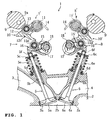
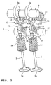
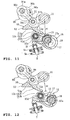
- FIGs. 1 to 6 show a valve drive mechanism according to a first embodiment.
- FIGs. 1 and 2 are a sectional side view and a front oblique view, respectively, of the valve drive mechanism of the first embodiment.
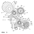
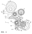
- FIGs. 3 and 4 are enlarged views of essential parts.
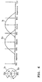
- FIGs. 5 and 6 show lift curves.
- the first embodiment is an example of applying the teaching of the present invention to an intake side valve drive mechanism, adapted that the intake valve opens as usual in the suction stroke and opens slightly also in the expansion stroke in particular at the time the engine starts.
- reference numeral 1 stands for a valve drive mechanism of a water-cooled, four-stroke cycle, in-line, multi-cylinder, 4-valve engine, and is constituted as described below.
- a combustion recess 2b constituting the cylinder head side portion of the combustion chamber is formed in the bottom joining face 2a portion located on the cylinder block side of the cylinder head 2.
- the combustion recess 2b is provided with two intake valve openings 3a, 3a, and two exhaust valve openings 4a, 4a.
- the intake valve openings 3a and the exhaust valve openings 4a each leads out through an intake port 3 and an exhaust port 4 respectively to outside connection openings.
- catalyst is disposed in the middle of an exhaust pipe connected to the exhaust port 4. The catalyst is activated when it reaches a specified temperature to purify hydrocarbon (HC), carbon monoxide (CO), and nitrogen oxides (NOx) by catalysis.
- Each intake valve opening 3a and each exhaust valve opening 4a are opened and closed respectively with the valve head 5a of the intake valve 5 and the valve head 6a of the exhaust valve 6.
- the intake valve 5 and the exhaust valve 6 are respectively urged in the closing direction with valve springs 5e and 6e respectively interposed between retainers 5c, 6c attached axially immovably at the top end portions of valve shafts 5b, 6b and valve seats 5d, 6d placed on the seating face of a cylinder head 2.
- An intake side valve drive mechanism 7 and an exhaust side valve drive mechanism 8 are disposed respectively above the intake valve 5 and the exhaust valve 6. Since the valve drive mechanisms 7, 8 are the same in constitution except for some parts, mainly the intake side valve drive mechanism 7 is explained below, and explanation on the exhaust side valve drive mechanism 8 is made only for parts different from those on the intake side one.
- the intake side valve drive mechanism 7 comprises: an intake camshaft (drive shaft) 9, an intake rocker arm (valve opening and closing member) 16 receiving the rotation of the intake camshaft 9 and driving the intake valve 5 to open and close, and a variable mechanism 7' interposed between the intake rocker arm 16 and the intake camshaft 9 for changing the manner of transmitting the rotation of the intake camshaft 9 to the intake rocker arm 16.
- the variable mechanism 7' comprises an intake rocker cam 10 driven with the intake cam nose 9a of the intake camshaft 9, and an intake intermediate rocker 15 driven with the intake rocker cam 10.
- the intake rocker arm 16 rocks.
- the intake valve 5 moves back and forth in the axial direction, so that the intake valve opening 3a is opened and closed.
- the intake cam nose 9a, the intake rocker cam 10, the intake intermediate rocker 15, and the intake rocker arm 16 are provided for every intake valve.
- the intake camshaft 9 is disposed parallel to the crankshaft (not shown) and supported for rotation about its axis but not to be immovable in directions normal to and along its axis, by means of a cam journal portion formed on the cylinder head 2 and a cam cap attached to the top joining face of the cam journal portion.
- the intake cam nose 9a is formed with the intake cam noses 9a, one each for left and right intake valves 5, 5.
- Each intake cam nose 9a has, as shown in FIG. 3, a base circle portion 9b of a certain outside diameter, and a main nose portion 9c of a specified cam profile for opening the intake valve 5 in the suction stroke.
- a sub nose portion 9d is formed for opening the intake valve 5 by a required small opening or by only a small lift in the expansion stroke.
- the sub nose portion 9d is of a shape in which part of the base circle portion 9b is formed to be an arcuately recessed portion and the recessed portion and the base circle portion are smoothly interconnected.
- the geometry of the sub nose portion 9d is appropriately selected to produce intended valve open period and lift amount in the expansion stroke.
- the intake rocker arm 16 is constituted that left and right arm portions 16b extending forward from ring-shaped left and right base portions 16a are interconnected through a bottom wall 16c to form a single member.
- the base portions 16a are supported for up and down rocking motion, immovable in both the axial direction and the direction normal to the axial direction, by means of a rocker shaft (control shaft) 17 disposed parallel to the intake camshaft 9 on the cylinder axis side.
- the fore-end underside of the bottom wall 16c is formed with a valve pressing face 16d for depressing a shim 5f attached to the top end of the intake valve 5.
- the inside face of each arm portion 16b is formed with a pressed face 16e of a ledge shape to be pressed with a pressing face 15e, to be described later, of the intermediate rocker 15.
- the pressed face 16e is formed, as seen in the cam axis direction when the valve is fully closed, to be an arc of radius r centered on the rocking center (a) of the intake rocker cam 10.
- Part of the rocker shaft 17 between the left and right base portions 16a, 16a is formed with an eccentric pin portion 17a smaller in diameter than other parts and displaced radially outward from the axis (b) of the rocker shaft 17.
- the eccentric pin portion 17a rotates along the circle (c) about the axis (b).
- a semicircular engagement base portion 15a of the intake intermediate rocker 15 engages rotationally with the eccentric pin portion 17a.
- the engagement base portion 15a and the eccentric pin portion 17a are interconnected through a plate spring 18 to be relatively rotational but inseparable from each other.
- the engagement base portion 15a of the intake intermediate rocker 15 is formed integrally with left and right arm portions 15b, 15b, extending forward.
- a rocker roller 15d is provided between fore-ends of the left and right arm portions 15b, 15b.
- the rocker roller 15d is joumaled with a roller pin 15c running in the axial direction of the rocker shaft through the left and right arm portions 15b, 15b.
- the front end undersides of the left and right arm portions 15b, 15b are formed with pressing faces 15e respectively for pressing left and right pressed faces 16e of the rocker arm 16.
- the rocker shaft 17 is constituted to be rotatable to any angular position by means of a drive mechanism (not shown) such as a servomotor.
- a drive mechanism such as a servomotor.
- the rocker roller 15d and the pressing face 15e of the intake intermediate rocker 15 move along the pressed face 16e, so that the effective arm length of the rocker arm 16 and the position of the rocker arm 16 relative to the rocker cam 10 change.
- the drive mechanism controls the angular position of the rocker shaft 17 so that the opening angle and the lift amount of the intake valve increase according to the increase, for example, in the amount of accelerator pedal depression.
- the intake rocker cam 10 comprises: a rocker arm main part 12 supported for rotation but immovable in both normal to axis direction and axial direction with a rocker shaft 11 disposed parallel to the intake camshaft 9, a rocker roller 13 axially supported on the rocker arm main part 12, and a forcing spring 14 forcing the rocker arm main part 12 clockwise so that the rocker roller 13 is in constant rolling contact with the cam nose 9a.
- the rocker arm main part 12 in rough description, is constituted with a cylindrical base end portion 12a, axially supported on the rocker shaft 11 and formed integrally with an arm portion 12b extending forward, with the fore-end portion of the arm portion 12b formed integrally with a rocker cam face 12c.
- the arm portion 12b is formed with a roller placing space 12d of a slit shape running through vertically.
- the rocker roller 13 is placed in the roller placing space 12d.
- the rocker roller 13 is journaled on a roller pin 12e which runs through the arm portion 12b parallel to the rocker shaft 11.
- the rocker cam face 12c comprises: a base circle portion 12f, a main lift portion 12g continuous on the fore-end side of the base circle portion 12f, and a sub lift portion 12h located on the base end side of the base circle portion 12f, with respective portions forming a continuous surface.
- the rocker arm main part 12 is disposed so that the sub lift portion 12h is located on near side to the rocker shaft 17 while the main lift portion 12g on far side from the rocker shaft 17.
- the base circle portion 12f is of a semicircular shape of a radius R centered on the rocking center (a) or the axis of the rocker shaft 11. Therefore, while the base circle portion 12f is in rolling contact with the rocker roller 15d, the rocking angle of the intermediate rocker 15 and so the rocker arm 16 remains unchanged at zero even if the rocking angle of the rocker cam 10 changes, so that the intake valve 5 is held in fully closed position without a lift.
- the main lift portion 12g as part of the main nose portion 9c of the intake camshaft 9 pressing the rocker roller 13 comes closer to its top portion, that is, as the rocking angle of the rocker cam 10 increases, lifts the intake valve 5 by greater amount.
- the main nose portion 9c in this embodiment is made up of: a ramp range for a constant speed, an acceleration range for varied speeds, and a deceleration range.
- valve drive mechanism 1 of this embodiment With the valve drive mechanism 1 of this embodiment, the angular position (rotary angular amount) of the rocker shaft (control shaft) 17 is controlled.
- the intermediate rocker 15 is therefore moved back and forth along the pressed face 16e, so that the open period and the lift amount of the valve are controlled.
- the angular position of the rocker shaft 17 is controlled so that the rocker roller 15d of the intermediate rocker 15 is located at the fore-end of the rocker arm 16.
- the open period and the lift amount of the intake valve 5 and the exhaust valve 6 become as shown in FIG. 6: an intake side lift curve 10 and an exhaust side lift curve E0.
- the intake valve 5 in the suction stroke is open over a range for example from about 50 degrees before the top dead center to about 70 degrees after the bottom dead center, and the lift amount becomes a maximum.
- the exhaust valve 6 is open over a range from about 70 degrees before the bottom dead center to about 50 degrees after the top dead center, and the lift amount becomes a maximum.
- the exhaust side valve drive mechanism 8 At the time the engine starts, for example for a period of 5 seconds after cranking starts, with the exhaust side valve drive mechanism 8, the angular position of the rocker shaft 17' is controlled so that the rocker roller 15d' is located in about the middle of the rocker arm 16'.
- the exhaust valve 6 is open in the exhaust stroke as shown with the lift curve E1 in FIG. 5 over a range for example from about 10 degrees before the bottom dead center to about the top dead center, with a lift amount of about half the above-mentioned maximum.
- the rotary angular position of the rocker shaft 17 is controlled so that, as shown with dash-and-double-dotted line in FIG. 4, the rocker roller 15d of the intermediate rocker 15 is located at the rear end of the rocker arm 16.
- the rocker roller 15d is held at part of the rocker cam face 12c on the sub lift portion 12h side end for a period the base circle portion 9b of the intake camshaft 9 is in rolling contact with the rocker roller 13. Therefore, in the suction stroke, the open period and the lift amount of the intake valve 5 become as shown with an intake side lift curve I1 in FIG. 5.
- the intake camshaft 9 further rotates clockwise from the state shown in FIG. 4, so that the intake valve 5 is open over a range from about 70 degrees after the top dead center to about 10 degrees after the bottom dead center, with a lift amount being about one-tenth of the maximum.
- this embodiment is constituted to slightly open the intake valve 5 in the expansion stroke, high concentration of hydrocarbon (HC) produced at the time the engine starts may be temporarily reduced. That is to say, at the time the engine starts (when cranking starts), in most cases combustion does not start or is imperfect for several initial revolutions of the engine. Therefore, it is feared that fuel mixture almost unburned flows directly into the exhaust system.
- the intake valve 5 slightly opens in the expansion stroke, at least part of the unburned gas returns to the exhaust port side in the exhaust stroke following the expansion stroke. Accordingly therefore, high concentration of HC flowing toward the exhaust port in the exhaust stroke after the expansion stroke may be reduced. The unburned gas returned to the intake port side is suctioned again into the combustion chamber together with mixture in the following intake stroke and burned. As a result, it is possible to reduce the discharged amount of high concentration of HC.
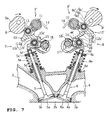
- FIGs. 7 and 8 illustrate a second embodiment.
- the same reference numerals and symbols denote the same or like parts as those in FIGs. 1 to 6.
- the teaching in the second embodiment is applied to the exhaust side valve drive mechanism. That is to say, it is adapted that the exhaust valve opens as usual in the exhaust stroke and opens slightly also in the compression stroke in particular for a short period of time immediately after the engine starts.
- the exhaust cam nose 9a' of the exhaust camshaft 9' comprises: a base circle portion 9b', a main nose portion 9c', and a sub nose portion 9d'.
- the rocker cam face 12c' of the exhaust rocker cam 10' comprises: a base circle portion 12f, a main lift portion 12g', and a sub lift portion 12h'.
- the rocker cam face 12c has the base circle portion 12f, and the main lift portion 12g, but not the sub lift portion 12h provided in the first embodiment.
- the valve drive mechanism of the second embodiment is controlled as described below for a period of time from the engine start to immediately thereafter, more specifically for example for about 60 seconds after the end of engine cranking.
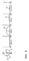
- the rocker shaft 17 With the intake side valve drive mechanism 7, the rocker shaft 17 is controlled to be in the same position as in the first embodiment. Therefore, the open period and the lift amount of the intake valve 5 in the suction stroke become the same as that in the first embodiment as shown with the lift curve I1 in FIG. 8. Incidentally, the intake valve 5 does not open in the expansion stroke.
- the rocker shaft 17' is controlled to be in the same angular position as in the first embodiment. Therefore, the exhaust valve 6 in the exhaust stroke follows the same lift curve E1 as that in the first embodiment as shown in FIG. 8.
- the sub nose portion 9d' of the exhaust camshaft 9' comes into rolling contact with the rocker roller 13.
- the exhaust rocker cam 10' slightly rotates counterclockwise as forced by the forcing spring 14.
- the sub lift portion 12h' depresses the rocker arm 16' through the rocker roller 15d' located on the exhaust side. Accordingly, the exhaust valve 6 opens slightly.
- the open period and the lift amount of the exhaust valve 6 in the compression stroke follow the lift curve E1' as shown in FIG. 8.
- the exhaust valve 6 in the compression stroke is open for a range from about 60 degrees after the bottom dead center to about 70 degrees before the top dead center.
- the second embodiment is adapted that the exhaust valve 6 opens slightly in the compression stroke, it is possible to activate catalyst quickly within a short period of time immediately after the engine starts and in particular removing, by catalyst, HC flowing into the exhaust system.
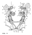
- FIGs. 9 and 10 illustrate a third embodiment.
- the same reference numerals and symbols denote the same or like parts as those in FIGs. 1 to 8.
- the third embodiment is an example adapted that the exhaust valve slightly opens during idling.
- the valve drive mechanism 8 in the third embodiment is adapted like the second embodiment that the exhaust cam nose 9a' of the exhaust camshaft 9' has: a base circle portion 9b', a main nose portion 9c', and a sub nose portion 9d'.
- the rocker cam face 12c' of the exhaust rocker cam 10' has: a base circle portion 12f, a main lift portion 12g', and a sub lift portion 12h.'
- the rocker cam face 12c has the base circle portion 12f, and the main lift portion 12g, but not the sub lift portion 12h provided in the first embodiment.
- the valve drive mechanism of the third embodiment is controlled during idling operation as described below.
- the rocker shaft 17 is controlled so that the rocker roller 15d recedes further than in the second embodiment. Therefore, the open period and the lift amount in the suction stroke of the intake valve 5 become as shown with the lift curve 12 in FIG. 10, still smaller than that in the second embodiment. Incidentally, the intake valve 5 does not open in the expansion stroke.
- the rocker shaft 17' is controlled so that the rocker roller 15d moves further forward than in the second embodiment. Therefore, the exhaust valve 6 in the exhaust stroke follows the lift curve E2 (FIG. 10) which is the same in both open period and lift amount as the lift curve E0 but slightly advanced in angle.
- the sub nose portion 9d' of the exhaust camshaft 9' comes into rolling contact with the rocker roller 13. Accordingly, the exhaust rocker cam 10' slightly rotates counterclockwise due to elastic force of the forcing spring 14.
- the sub lift portion 12h' depresses the rocker arm 16' through the rocker roller 15d' located on the exhaust side.
- the exhaust valve 6 opens slightly.
- the open period and the lift amount of the exhaust valve 6 in the compression stroke become as shown with the lift curve E1' in FIG. 10.
- the exhaust valve 6 is open during a period of time from about 15 degrees after the bottom dead center to about 65 degrees after the bottom dead center.
- the third embodiment is adapted that the exhaust valve 6 opens slightly in the compression stroke, it is possible in the idling operation to improve fuel economy, stabilize combustion, and purify by catalysis.
- the intake valve opening is made minimum and the ignition timing is advanced.
- the catalyst is undesirably cooled because of decrease in the heat amount flowing into the exhaust system, resulting in unsatisfactory exhaust gas purification. Therefore, there is inevitably a limit to improvement in fuel economy by reducing the intake valve opening.
- the third embodiment is adapted that the exhaust valve opens slightly in the compression stroke, part of mixture is pushed out into the exhaust pipe and bumed there. As a result, it is possible to avoid decrease in catalyst temperature and maintain purification by catalysis.
- the third embodiment is adapted as described above that part of mixture is pushed into the exhaust pipe and is burned there, the energy of burned mixture is directly used to heat up the catalyst with high efficiency, resulting in improved fuel economy.
- the intake valve opens slightly in the expansion stroke at the time the engine starts and the exhaust valve opens slightly in the compression stroke immediately after the engine starts, or further that the exhaust valve opens slightly in the compression stroke also during idling.
- the exhaust valve opens slightly in the compression stroke also during idling.
- the first to third embodiments described are adapted that the camshaft 9 has the function of rocking the rocker cam 10 toward the valve opening side only, and the forcing spring 14 is used to rock the rocker cam 10 toward the valve closing side.
- the fourth embodiment uses the crankshaft 90 in place of the camshaft 9.
- the crankshaft 90 comprises: a shaft main part 90a, a pair of disk-shaped crank arm portions 90b, 90b formed integral with and greater in diameter than the shaft main part 90a, and a crankpin 90c formed between the crank arm portions 90b, 90b as displaced from the axis of the shaft main part 90a.
- the crankshaft 90 is connected through a connecting rod 91 to the arm main part 12 of the rocker cam 10.
- One end 91 a of the connecting rod 91 is connected to the crankpin 90c while the other end 91 b is connected through the connection pin 91 c to the arm main part 12.
- the forcing spring 14 used in the first to third embodiments is not required.
- the rocker cam 10 is forcibly driven in both valve opening and closing directions along with the rotation of the crankshaft 90.
- the angular position of the rocker shaft 17 is controlled as shown in FIG. 11, so that the rocker roller 15d of the intermediate rocker 15 comes to the fore-end of the rocker arm 16. This maximizes the open period and the lift amount of the intake valve 5.
- the angular position of the rocker shaft 17 is controlled so that the rocker roller 15d of the intermediate rocker 15 comes to the rear end of the rocker arm 16.
- the sub lift portion 12h of the rocker cam face 12c of the rocker cam 10 depresses the rocker roller 15d, to thereby slightly depresses the intake valve 5 to open slightly (See the lift curve l1' in FIG. 5).
- this embodiment is adapted as described above that the rocker cam 10 is forced to rock in both opening and closing directions by means of the crankshaft 90, it is possible to securely depress the rocker arm 16 by means of the sub lift portion 12h, and accordingly to open the intake valve 5 securely.
- valve drive mechanism comprising: the camshaft or crankshaft, the rocker cam driven with the camshaft or crankshaft, the intermediate rocker driven with the rocker cam, and the rocker arm rocking together with the intermediate rocker.
- valve drive mechanisms to which the invention may be applied are not limited to those in the above embodiments. Rather, the present invention may also be applied for example to the valve drive mechanisms shown in FIGs. 13 to 15.
- the valve drive mechanism 30 comprises a variable mechanism 30' interposed between the intake camshaft 31 and the rocker arm 34.
- the variable mechanism 30' comprises: a rocker lever 32 with its center roller 32a driven with the camshaft 31, and a guide cam 33 for guiding a roller 32b located at one end of the rocker lever 32.
- the other end 32c of the rocker lever 32 is connected to the rocker arm 34.
- one end of the rocker arm 34 is supported with a lash adjuster 35 while the other end is adapted to depress the top end of the intake valve 36.
- the base circle portion of the cam nose of the intake camshaft 31 is formed with a sub nose portion 31 a corresponding to the sub nose portion 9d in the first to third embodiments.
- one end of the guide cam 33 is formed with a raised sub lift portion 33a corresponding to the sub lift portion 12h in the first to third embodiments.
- the intake valve 36 opens as usual in the suction stroke and opens slightly also in the expansion stroke. In this way, the same effects as with the first to third embodiments are provided.
- variable mechanism 40' of the valve drive mechanism 40 comprises: a rocker lever 42 having a roller 42a located at one end thereof and rocked with the intake camshaft 41, and a guide cam 43 for guiding a roller 42b located in the center of the rocker lever 42.
- a rocker arm 44 is depressed with a cam face 42c located at the other end of the rocker lever 42.
- one end of the rocker arm 44 is supported with a lash adjuster 45 while the other end is adapted to depress the top end of the intake valve 46.
- Reference numeral 47 denotes a forcing spring that forces the rocker lever 42 against the guide cam 43.
- the position where the roller 42b of the rocker lever 42 contacts the guide cam 44 changes as the guide cam 43 is rocked in the direction indicated with an arrow in the drawing, so that the open period and the lift amount of the intake valve 46 changes.
- the base circle portion of the cam nose of the intake camshaft 41 is formed with a sub nose portion 41a corresponding to the sub nose portion 9d in the first to third embodiments.
- one end of the cam face of the guide cam 43 is formed with a raised sub lift portion 43a corresponding to the sub lift portion 12h in the first to third embodiments.
- the intake valve 46 opens as usual in the suction stroke and opens slightly also in the expansion stroke. In this way, the same effects as with the first to third embodiments are provided.
- valve drive mechanism 50 shown as a seventh embodiment in FIG. 15, a variable mechanism 50' is interposed between a drive shaft 51 serving as a drive source, and a lifter 52 serving as a valve opening and closing member.
- the drive shaft 51 is integrally formed with an eccentric portion 51 a to support the base portion of a link arm 51 b for relative rotation. As the drive shaft 51 is driven to rotate by the engine rotation, the fore-end portion 51 c of the link arm 51 b moves up and down, as seen in the drawing, along with the rotation of the eccentric portion 51 a.
- the variable mechanism 50' comprises: a rocker link 52 with its one end connected to the fore-end 51 c of the link arm 51 b, and a rocker cam 54 connected through a link plate 53 to the other end of the rocker link 52.
- the rocker link 52 makes rocking motion which is transmitted through the link plate 53 to the rocker cam 54.
- the rocking motion of the rocker cam 54 drives the lifter 52 to move up and down, which in turn causes the intake valve 56 to open and close.
- the rocker link 52 is supported for relative rotation by means of the eccentric cam portion 52b of the eccentric shaft 52a. Therefore, the center of rocking motion of the rocker link 52 changes with the rotation of the eccentric shaft 52a. As a result, manner of transmitting the rotation of the drive shaft 51 to the lifter 52 changes, so that the open period and the lift amount of the intake valve 56 changes.
- the cam face 54a of the rocker cam 54 is formed with a sub lift portion 54b corresponding to the sub lift portion 12h in the fourth embodiment described before.
- the rocker cam 54 is forcibly driven in both valve opening and closing directions along with the rotation of the drive shaft 51, so that the intake valve is opened and closed securely.
- the intake valve 56 opens normally in the suction stroke and opens slightly also in the expansion stroke. In this way, the same effects as with the first to fourth embodiments are provided.
- valve drive mechanism for an engine, comprising: a drive shaft to be a drive source, a valve opening and closing member to which the rotation of the drive shaft is transmitted so as to open and close a valve, and a variable mechanism interposed between the valve opening and closing member and the drive shaft, wherein the variable mechanism changes the manner of transmitting the rotation of the drive shaft to the valve opening and closing member to make the open period of the valve continuously variable, wherein the valve open period is set to have a main valve open period for the valve to be open in suction or exhaust stroke and a sub valve open period for the valve to be open in expansion or compression stroke during a specific operation range; outflow of part of combustion gas or unburned gas into an intake system is allowed during the sub valve open period in the expansion stroke; and outflow of part of mixture into an exhaust system is allowed during the sub valve open period in the compression stroke.
- the valve open period is set to have: the main valve open period in which the valve is open in the intake or exhaust stroke, and the sub valve open period in which the valve is open in expansion or compression stroke during specific operation range.
- an intake valve open period at the time the engine starts is set to have a main intake valve open period for the intake valve to be open in the suction stroke and a sub intake valve open period for the intake valve to be open in the expansion stroke, and outflow of part of combustion gas or unburned gas into the intake system is allowed during the sub intake valve open period.
- the intake valve open period at the time the engine starts is set to be the sub intake valve open period in which the intake valve is open in the expansion stroke. This results in that outflow of part of combustion gas or unburned gas into the intake system is allowed in the sub intake valve open period. As a result, it is possible to temporarily reduce high concentration of HC produced at the time the engine starts.
- an exhaust valve open period immediately after the engine starts is set to have a main exhaust valve open period for the exhaust valve to be open in the exhaust stroke and a sub exhaust valve open period for the exhaust valve to be open in the compression stroke, and outflow of part of mixture into the exhaust system is allowed during the sub exhaust valve open period. Since this embodiment is adapted that the exhaust valve is slightly open in the compression stroke, it is possible to activate catalyst quickly within a short period of time immediately after the engine starts, and in particular to purify HC flowing into the exhaust system by means of catalyst.
- the intake valve open period at the time the engine starts is set to have a main intake valve open period for the intake valve to be open in the suction stroke and a sub intake valve open period for the intake valve to be open in the expansion stroke, and outflow of part of combustion gas or unburned gas into the intake system is allowed during the sub intake valve open period
- an exhaust valve open period immediately after the engine starts is set to have a main exhaust valve open period for the exhaust valve to be open in the exhaust stroke and a sub exhaust valve open period for the exhaust valve to be open in the compression stroke, and outflow of part of mixture into the exhaust system is allowed during the sub exhaust valve open period.
- this embodiment is adapted that the intake valve opens slightly in the expansion stroke at the time the engine starts and that the exhaust valve opens slightly in the compression stroke immediately after the engine starts. Therefore, outflow of unburned gas into the exhaust system is restricted at the time the engine starts, and part of mixture is burned in the exhaust system immediately after the engine starts, so that the catalyst is quickly heated up and activated. As a result, it is possible to further restrict outward discharge of HC.
- an exhaust valve open period in an idling operation range is set to have a main exhaust valve open period for the exhaust valve to be open in the exhaust stroke and a sub exhaust valve open period for the exhaust valve to be open in the compression stroke, and outflow of part of mixture into the exhaust system is allowed during the sub exhaust valve open period. Since this embodiment is adapted that the exhaust valve opens slightly in the compression stroke in the idling operation range, it is possible to improve fuel economy, and stabilize and purify combustion by means of catalyst in the idling operation range. In the idling operation, the intake valve opening is made minimum and ignition timing is advanced for fuel economy and combustion stability.
- the drive shaft is an intake camshaft rotationally supported
- the valve opening and closing member is a rocker arm supported for rocking motion
- the variable mechanism comprises: a rocker cam supported for rocking motion and rock-driven with the intake camshaft, and an intermediate rocker rockably interposed between the cam face of the rocker cam and the rocker arm; the intermediate rocker is pressed with the cam face as the rocker cam rocks to rock the rocker arm, and the open period and the lift amount of the intake valve is made continuously controllable by changing relative positional relationship between the intermediate rocker and the cam face, and the cam face of the rocker cam has: a base circle portion, a main lift portion continuous on the fore-end side of the base circle portion, and a sub lift portion formed on the root end side of the base circle portion; the cam nose portion of the intake camshaft has a sub nose portion for driving the intermediate rocker in the opening direction using the sub lift portion of the cam face, to bring about the sub intake valve open period of the intake valve in the expansion stroke.
- the cam face of the rocker cam constituting the variable mechanism has the sub lift portion formed on the base end side of the base circle portion, and the cam nose portion of the intake camshaft has the sub nose portion for driving the intermediate rocker in the opening direction using the sub lift portion of the cam face.
- the drive shaft is an exhaust camshaft supported for rotation
- the valve opening and closing member is a rocker arm supported for rocking motion
- the variable mechanism comprises: a rocker cam supported for rocking motion and rock-driven with the exhaust camshaft, and an intermediate rocker rockably interposed between the cam face of the rocker cam and the rocker arm; the intermediate rocker is pressed with the cam face as the rocker cam rocks to rock the rocker arm, and the open period and the lift amount of the exhaust valve is made continuously controllable by changing relative positional relationship between the intermediate rocker and the cam face, and the cam face of the rocker cam has: a base circle portion, a main lift portion continuous on the fore-end side of the base circle portion, and a sub lift portion formed on the root end side of the base circle portion; the cam nose portion of the exhaust camshaft has a sub nose portion for driving the intermediate rocker in the opening direction using the sub lift portion of the cam face, to bring about the sub exhaust valve open period of the exhaust valve in the compression stroke.
- the cam face of the rocker cam constituting the variable mechanism has the sub lift portion formed on the base end side of the base circle portion, and the cam nose portion of the exhaust camshaft has the sub nose portion for driving the intermediate rocker in the opening direction using the sub lift portion of the cam face.
- the drive shaft is an intake camshaft or an exhaust camshaft
- the valve opening and closing member is a rocker arm supported for rocking motion
- the variable mechanism comprises an intake side variable mechanism and an exhaust side variable mechanism
- the intake side variable mechanism comprising: a rocker cam rock-driven with the intake camshaft supported for rocking motion, and an intermediate rocker rockably disposed between the cam face of the rocker cam and the rocker arm; the intermediate rocker is pressed with the cam face as the rocker cam rocks to rock the rocker arm, and the open period and the lift amount of the intake valve is made continuously controllable by changing relative positional relationship between the intermediate rocker and the cam face
- the cam face of the rocker cam has: a base circle portion, a main lift portion continuous on the fore-end side of the base circle portion, and a sub lift portion formed on the root end side of the base circle portion;
- the cam nose portion of the intake camshaft has a sub nose portion for driving the intermediate rocker in the opening direction using the sub lift portion of the cam face
- This embodiment is adapted that the intake side variable mechanism causes the intake valve to open slightly in the expansion stroke and that the exhaust side variable mechanism causes the exhaust valve to open slightly in the compression stroke. Therefore, outflow of unburned gas into the exhaust system is restricted at the time the engine starts, and part of mixture is burned in the exhaust system immediately after the engine starts, so that the catalyst is heated up and activated quickly. As a result, it is possible to further restrict outward discharge of HC.
- a valve open period is set to have a main valve open period I1, E1 in which the valve is open in a suction or exhaust stroke and a sub valve open period I1', E1' in which the valve is open in an expansion or compression stroke in a specific operation range.
- valve drive mechanism for an engine, comprising: a drive shaft to be a drive source, a valve opening and closing member to which the rotation of the drive shaft is transmitted so as to open and close a valve, and a variable mechanism interposed between the valve opening and closing member and the drive shaft, the variable mechanism changing the manner of transmitting the rotation of the drive shaft to the valve opening and closing member to make the open period of the valve continuously variable, wherein the valve open period is set to have a main valve open period for the valve to be open in suction or exhaust stroke, and a sub valve open period for the valve to be open in expansion or compression stroke during a specific operation range, outflow of part of combustion gas or unburned gas into an intake system is allowed during the sub valve open period in the expansion stroke, and outflow of part of mixture into an exhaust system is allowed during the sub valve open period in the compression stroke.
- an intake valve open period at the time the engine starts is set to have a main intake valve open period for the intake valve to be open in the suction stroke and a sub intake valve open period for the intake valve to be open in the expansion stroke, and outflow of part of combustion gas or unburned gas into the intake system is allowed during the sub intake valve open period.
- an exhaust valve open period immediately after the engine start is set to have a main exhaust valve open period for the exhaust valve to be open in the exhaust stroke and a sub exhaust valve open period for the exhaust valve to be open in the compression stroke, and outflow of part of mixture into the exhaust system is allowed during the sub exhaust valve open period.
- the intake valve open period at the time the engine starts is set to have a main intake valve open period for the intake valve to be open in the suction stroke and a sub intake valve open period for the intake valve to be open in the expansion stroke, and outflow of part of combustion gas or unbumed gas into the intake system is allowed during the sub intake valve open period
- an exhaust valve open period immediately after the engine starts is set to have a main exhaust valve open period for the exhaust valve to be open in the exhaust stroke and a sub exhaust valve open period for the exhaust valve to be open in the compression stroke, and outflow of part of mixture into the exhaust system is allowed during the sub exhaust valve open period.
- an exhaust valve open period in an idling operation range is set to have a main exhaust valve open period for the exhaust valve to be open in the exhaust stroke and a sub exhaust valve open period for the exhaust valve to be open in the compression stroke, and outflow of part of mixture into the exhaust system is allowed during the sub exhaust valve open period.
- the drive shaft is an intake camshaft rotationally supported
- the valve opening and closing member is a rocker arm supported for rocking motion
- the variable mechanism comprises: a rocker cam supported for rocking motion and rock-driven with the intake camshaft, and an intermediate rocker rockably interposed between the cam face of the rocker cam and the rocker arm; the intermediate rocker is pressed with the cam face as the rocker cam rocks to rock the rocker arm, and the open period and the lift amount of the intake valve is made continuously controllable by changing relative positional relationship between the intermediate rocker and the cam face, and the cam face of the rocker cam has: a base circle portion, a main lift portion continuous on the fore-end side of the base circle portion, and a sub lift portion formed on the root end side of the base circle portion; the cam nose portion of the intake camshaft has a sub nose portion for driving the intermediate rocker in the opening direction using the sub lift portion of the cam face, to bring about the sub intake valve open period of
- the drive shaft is an exhaust camshaft rotationally supported
- the valve opening and closing member is a rocker arm supported for rocking motion
- the variable mechanism comprises: a rocker cam supported for rocking motion and rock-driven with the exhaust camshaft, and an intermediate rocker rockably interposed between the cam face of the rocker cam and the rocker arm; the intermediate rocker is pressed with the cam face as the rocker cam rocks to rock the rocker arm, and the open period and the lift amount of the exhaust valve is made continuously controllable by changing relative positional relationship between the intermediate rocker and the cam face, and the cam face of the rocker cam has: a base circle portion, a main lift portion continuous on the fore-end side of the base circle portion, and a sub lift portion formed on the root end side of the base circle portion; the cam nose portion of the exhaust camshaft has a sub nose portion for driving the intermediate rocker in the opening direction using the sub lift portion of the cam face, to bring about the sub exhaust valve open period of
- the drive shaft is an intake camshaft or an exhaust camshaft
- the valve opening and closing member is a rocker arm supported for rocking motion
- the variable mechanism comprises an intake side variable mechanism and an exhaust side variable mechanism
- the intake side variable mechanism comprising: a rocker cam rock-driven with the intake camshaft supported for rocking motion, and an intermediate rocker rockably disposed between the cam face of the rocker cam and the rocker arm;
- the intermediate rocker is pressed with the cam face as the rocker cam rocks to rock the rocker arm, and the open period and the lift amount of the intake valve is made continuously controllable by changing relative positional relationship between the intermediate rocker and the cam face
- the cam face of the rocker cam has: a base circle portion, a main lift portion continuous on the fore-end side of the base circle portion, and a sub lift portion formed on the root end side of the base circle portion
- the cam nose portion of the intake camshaft has a sub nose portion for driving the intermediate rocker in the opening direction
Landscapes
- Engineering & Computer Science (AREA)
- Mechanical Engineering (AREA)
- General Engineering & Computer Science (AREA)
- Chemical & Material Sciences (AREA)
- Combustion & Propulsion (AREA)
- Valve Device For Special Equipments (AREA)
- Output Control And Ontrol Of Special Type Engine (AREA)
Abstract
Description
- The present invention relates to a valve drive mechanism for an engine being capable of continuously controlling the open period of an intake valve or exhaust valve.
- Valve drive mechanisms for engines capable of continuously controlling the open period and lift amount of an intake or exhaust valve have been put to practical use. An exemplary valve drive mechanism of this type is typically disclosed in
DE 4223172 C1 (Patent Document 1). This mechanism is adapted that a rocker cam supported for rocking motion is driven with a camshaft, and an intake or exhaust valve is driven to open and close with the rocker cam. And the rocking center of the rocker cam is made variable, so that the open period and lift amount of the valve are made continuously changeable. - There is a conventional problem that, at the time of starting an engine by cranking, or immediately after the engine starts, fuel remaining unburned is undesirably discharged or combustion of fuel, although started, is unstable, resulting in a large amount of discharge in particular of hydrocarbon (HC).
- The present invention has been made in view of the conventional problem described. Therefore, the object of the invention is to provide a valve drive mechanism for engines that makes it possible to reduce the HC discharge amount particularly at the time the engine starts, and/or immediately after the engine starts, and/or in the idling operation range, and further improve fuel economy particularly in the idling operation range.
- This objective is solved in an inventive manner by a valve drive mechanism for an engine, wherein a valve open period is set to have a main open period, in which the valve is open in a suction or in an exhaust stroke, and a sub open period, in which the valve is open in an expansion or in a compression stroke in a specific operation range, and wherein during the sub open period in the expansion stroke, outflow of part of combustion gas or unburned gas into the intake system is allowed, and/or during the sub open period in the compression stroke, outflow of part of mixture into the exhaust system is allowed.
- Preferably, the valve drive mechanism further comprises a drive shaft to be a drive source, a valve opening and closing member to which the rotation of the drive shaft is transmitted so as to open and close the valve, and a variable mechanism interposed between the valve opening and closing member and the drive shaft, the variable mechanism changing the manner of transmitting the rotation of the drive shaft to the valve opening and closing member to make the open period of the valve continuously variable, wherein the valve open period is set to have the main open period for the valve to be open in suction or exhaust stroke, and the sub open period for the valve to be open in expansion or compression stroke during a specific operation range, wherein outflow of part of combustion gas or unburned gas into an intake system is allowed during the sub open period in the expansion stroke, and wherein outflow of part of mixture into an exhaust system is allowed during the sub open period in the compression stroke.
- According to a preferred embodiment, an intake valve open period at the time the engine starts is set to have a main intake valve open period for the intake valve to be open in the suction stroke and a sub intake valve open period for the intake valve to be open in the expansion stroke, and outflow of part of combustion gas or unbumed gas into the intake system is allowed during the sub intake valve open period.
- According to another preferred embodiment, an exhaust valve open period immediately after the engine starts is set to have a main exhaust valve open period for the exhaust valve to be open in the exhaust stroke and a sub exhaust valve open period for the exhaust valve to be open in the compression stroke, and outflow of part of mixture into the exhaust system is allowed during the sub exhaust valve open period.
- According to yet another preferred embodiment, an exhaust valve open period in an idling operation range is set to have a main exhaust valve open period for the exhaust valve to be open in the exhaust stroke and a sub exhaust valve open period for the exhaust valve to be open in the compression stroke, and outflow of part of mixture into the exhaust system is allowed during the sub exhaust valve open period.
- According to still another preferred embodiment, the drive shaft is an intake camshaft rotationally supported, the valve opening and closing member is a rocker arm supported for rocking motion, and the variable mechanism comprises a rocker cam supported for rocking motion and rock-driven with the intake camshaft, and an intermediate rocker rockably interposed between the cam face of the rocker cam and the rocker arm, wherein the intermediate rocker is pressed with the cam face as the rocker cam rocks to rock the rocker arm, and the open period and the lift amount of the intake valve is made continuously controllable by changing relative positional relationship between the intermediate rocker and the cam face.
- Within this embodiment, it is beneficial, if the cam face of the rocker cam has a base circle portion, a main lift portion continuous on the fore-end side of the base circle portion, and a sub lift portion formed on the root end side of the base circle portion, and if the cam nose portion of the intake camshaft has a sub nose portion for driving the intermediate rocker in the opening direction using the sub lift portion of the cam face, to bring about the sub intake valve open period of the intake valve in the expansion stroke.
- According to an alternative embodiment, the drive shaft is an exhaust camshaft rotationally supported, the valve opening and closing member is a rocker arm supported for rocking motion, and the variable mechanism comprises a rocker cam supported for rocking motion and rock-driven with the exhaust camshaft, and an intermediate rocker rockably interposed between the cam face of the rocker cam and the rocker arm, and the intermediate rocker is pressed with the cam face as the rocker cam rocks to rock the rocker arm, and the open period and the lift amount of the exhaust valve is made continuously controllable by changing relative positional relationship between the intermediate rocker and the cam face.
- Within this alternative embodiment, it is beneficial, if the cam face of the rocker cam has a base circle portion, a main lift portion continuous on the fore-end side of the base circle portion, and a sub lift portion formed on the root end side of the base circle portion, and the cam nose portion of the exhaust camshaft has a sub nose portion for driving the intermediate rocker in the opening direction using the sub lift portion of the cam face, to bring about the sub exhaust valve open period of the exhaust valve in the compression stroke.
- According to another alternative embodiment, the intake camshaft and the exhaust camshaft are drive shafts, the valve opening and closing member is a rocker arm supported for rocking motion, the variable mechanism comprises an intake side variable mechanism and an exhaust side variable mechanism, with the intake side variable mechanism comprising a rocker cam rock-driven with the intake camshaft supported for rocking motion, and an intermediate rocker rockably disposed between the cam face of the rocker cam and the rocker arm, wherein the intermediate rocker is pressed with the cam face as the rocker cam rocks to rock the rocker arm, and the open period and the lift amount of the intake valve is made continuously controllable by changing relative positional relationship between the intermediate rocker and the cam face, and the cam face of the rocker cam has: a base circle portion, a main lift portion continuous on the fore-end side of the base circle portion, and a sub lift portion formed on the root end side of the base circle portion; the cam nose portion of the intake camshaft has a sub nose portion for driving the intermediate rocker in the opening direction using the sub lift portion of the cam face, to bring about the sub intake valve open period of the intake valve in the expansion stroke, and with the exhaust side variable mechanism comprising a rocker cam supported for rocking motion and rock-driven with the exhaust camshaft, and an intermediate rocker rockably interposed between the cam face of the rocker cam and the rocker arm, wherein the intermediate rocker is pressed with the cam face as the rocker cam rocks to rock the rocker arm, and the open period and the lift amount of the exhaust valve is made continuously controllable by changing relative positional relationship between the intermediate rocker and the cam face, and the cam face of the rocker cam has: a base circle portion, a main lift portion continuous on the fore-end side of the base circle portion, and a sub lift portion formed on the root end side of the base circle portion, wherein the cam nose portion of the exhaust camshaft has a sub nose portion for driving the intermediate rocker in the opening direction using the sub lift portion of the cam face, to bring about the sub exhaust valve open period of the exhaust valve in the compression stroke.
- Further, it is preferred, if an intake valve opens slightly in the expansion stroke at the time the engine starts and/or an exhaust valve opens slightly in the compression stroke immediately after the engine starts, and/or the exhaust valve opens slightly in the compression stroke also during idling.
- In the following, the present invention is explained in further details, with respect to several embodiments thereof in conjunction with the accompanying drawings, wherein:
- FIG. 1
- is a sectional side view of a valve drive mechanism as the first embodiment,
- FIG. 2
- is a front oblique view of the first embodiment of the mechanism,
- FIG.3
- is an enlarged view of essential parts of the first embodiment of the mechanism,
- FIG.4
- is an enlarged view of essential parts of the first embodiment of the mechanism,
- FIG. 5
- shows a lift curve of the first embodiment of the mechanism,
- FIG. 6
- shows a lift curve of the first embodiment of the mechanism,
- FIG. 7
- is a sectional side view of the second embodiment of the mechanism,
- FIG. 8
- shows a lift curve of the second embodiment of the mechanism,
- FIG. 9
- is a sectional side view of the third embodiment of the mechanism,
- FIG. 10
- shows a lift curve of the third embodiment of the mechanism,
- FIG. 11
- is a side view of the fourth embodiment,
- FIG. 12
- is a sectional side view of the fourth embodiment of the mechanism,
- FIG. 13
- is a simplified side view of the fifth embodiment of the mechanism,
- FIG. 14
- is a simplified side view of the sixth embodiment of the mechanism, and
- FIG. 15
- is a simplified side view of the seventh embodiment of the mechanism.
-
- 1: valve drive mechanism
- 5, 6: intake and exhaust valves
- 7', 8', 30', 40', 50': variable mechanism
- 9: camshaft (drive shaft)
- 9a: cam nose portion
- 9d: sub nose portion
- 10: rocker cam
- 12c: cam face
- 12f: base circle portion
- 12g: main lift portion
- 12d: sub lift portion
- 15: intermediate rocker
- 16: rocker arm (valve opening and closing member)
- 52: lifter (valve opening and closing member)
- 90: crankshaft (drive shaft)
- E0, E1, E2: main exhaust valve open period
- E1', E2': sub exhaust valve open period
- I0, I1, I2: main intake valve open period
- I0': sub intake valve open period
- Embodiments are described below in reference to the accompanying drawings.
- FIGs. 1 to 6 show a valve drive mechanism according to a first embodiment. FIGs. 1 and 2 are a sectional side view and a front oblique view, respectively, of the valve drive mechanism of the first embodiment. FIGs. 3 and 4 are enlarged views of essential parts. FIGs. 5 and 6 show lift curves.
- The first embodiment is an example of applying the teaching of the present invention to an intake side valve drive mechanism, adapted that the intake valve opens as usual in the suction stroke and opens slightly also in the expansion stroke in particular at the time the engine starts.
- In the drawings, reference numeral 1 stands for a valve drive mechanism of a water-cooled, four-stroke cycle, in-line, multi-cylinder, 4-valve engine, and is constituted as described below. A
combustion recess 2b constituting the cylinder head side portion of the combustion chamber is formed in thebottom joining face 2a portion located on the cylinder block side of thecylinder head 2. Thecombustion recess 2b is provided with twointake valve openings exhaust valve openings intake valve openings 3a and theexhaust valve openings 4a each leads out through anintake port 3 and anexhaust port 4 respectively to outside connection openings. Although not shown, catalyst is disposed in the middle of an exhaust pipe connected to theexhaust port 4. The catalyst is activated when it reaches a specified temperature to purify hydrocarbon (HC), carbon monoxide (CO), and nitrogen oxides (NOx) by catalysis. - Each
intake valve opening 3a and eachexhaust valve opening 4a are opened and closed respectively with thevalve head 5a of theintake valve 5 and thevalve head 6a of theexhaust valve 6. Theintake valve 5 and theexhaust valve 6 are respectively urged in the closing direction withvalve springs retainers valve shafts valve seats cylinder head 2. - An intake side
valve drive mechanism 7 and an exhaust sidevalve drive mechanism 8 are disposed respectively above theintake valve 5 and theexhaust valve 6. Since thevalve drive mechanisms valve drive mechanism 7 is explained below, and explanation on the exhaust sidevalve drive mechanism 8 is made only for parts different from those on the intake side one. - The intake side
valve drive mechanism 7 comprises: an intake camshaft (drive shaft) 9, an intake rocker arm (valve opening and closing member) 16 receiving the rotation of theintake camshaft 9 and driving theintake valve 5 to open and close, and a variable mechanism 7' interposed between theintake rocker arm 16 and theintake camshaft 9 for changing the manner of transmitting the rotation of theintake camshaft 9 to theintake rocker arm 16. - The variable mechanism 7' comprises an
intake rocker cam 10 driven with theintake cam nose 9a of theintake camshaft 9, and an intakeintermediate rocker 15 driven with theintake rocker cam 10. As the intakeintermediate rocker 15 rocks, theintake rocker arm 16 rocks. As theintake rocker arm 16 rocks, theintake valve 5 moves back and forth in the axial direction, so that theintake valve opening 3a is opened and closed. Incidentally, theintake cam nose 9a, theintake rocker cam 10, the intakeintermediate rocker 15, and theintake rocker arm 16 are provided for every intake valve. - The
intake camshaft 9 is disposed parallel to the crankshaft (not shown) and supported for rotation about its axis but not to be immovable in directions normal to and along its axis, by means of a cam journal portion formed on thecylinder head 2 and a cam cap attached to the top joining face of the cam journal portion. Theintake cam nose 9a is formed with theintake cam noses 9a, one each for left andright intake valves intake cam nose 9a has, as shown in FIG. 3, abase circle portion 9b of a certain outside diameter, and amain nose portion 9c of a specified cam profile for opening theintake valve 5 in the suction stroke. Further in the approximate center of thebase circle portion 9b, asub nose portion 9d is formed for opening theintake valve 5 by a required small opening or by only a small lift in the expansion stroke. Thesub nose portion 9d is of a shape in which part of thebase circle portion 9b is formed to be an arcuately recessed portion and the recessed portion and the base circle portion are smoothly interconnected. Incidentally, the geometry of thesub nose portion 9d is appropriately selected to produce intended valve open period and lift amount in the expansion stroke. - The
intake rocker arm 16 is constituted that left andright arm portions 16b extending forward from ring-shaped left andright base portions 16a are interconnected through abottom wall 16c to form a single member. Thebase portions 16a are supported for up and down rocking motion, immovable in both the axial direction and the direction normal to the axial direction, by means of a rocker shaft (control shaft) 17 disposed parallel to theintake camshaft 9 on the cylinder axis side. - The fore-end underside of the
bottom wall 16c is formed with avalve pressing face 16d for depressing ashim 5f attached to the top end of theintake valve 5. The inside face of eacharm portion 16b is formed with a pressedface 16e of a ledge shape to be pressed with apressing face 15e, to be described later, of theintermediate rocker 15. The pressedface 16e is formed, as seen in the cam axis direction when the valve is fully closed, to be an arc of radius r centered on the rocking center (a) of theintake rocker cam 10. - Part of the
rocker shaft 17 between the left andright base portions eccentric pin portion 17a smaller in diameter than other parts and displaced radially outward from the axis (b) of therocker shaft 17. When therocker shaft 17 is rotated, theeccentric pin portion 17a rotates along the circle (c) about the axis (b). - A semicircular
engagement base portion 15a of the intakeintermediate rocker 15 engages rotationally with theeccentric pin portion 17a. Theengagement base portion 15a and theeccentric pin portion 17a are interconnected through aplate spring 18 to be relatively rotational but inseparable from each other. - The
engagement base portion 15a of the intakeintermediate rocker 15 is formed integrally with left andright arm portions rocker roller 15d is provided between fore-ends of the left andright arm portions rocker roller 15d is joumaled with aroller pin 15c running in the axial direction of the rocker shaft through the left andright arm portions right arm portions pressing faces 15e respectively for pressing left and right pressed faces 16e of therocker arm 16. - The
rocker shaft 17 is constituted to be rotatable to any angular position by means of a drive mechanism (not shown) such as a servomotor. As the angular position of therocker shaft 17 is changed with the drive mechanism, therocker roller 15d and thepressing face 15e of the intakeintermediate rocker 15 move along the pressedface 16e, so that the effective arm length of therocker arm 16 and the position of therocker arm 16 relative to therocker cam 10 change. Incidentally, the drive mechanism controls the angular position of therocker shaft 17 so that the opening angle and the lift amount of the intake valve increase according to the increase, for example, in the amount of accelerator pedal depression. - The
intake rocker cam 10 comprises: a rocker armmain part 12 supported for rotation but immovable in both normal to axis direction and axial direction with arocker shaft 11 disposed parallel to theintake camshaft 9, arocker roller 13 axially supported on the rocker armmain part 12, and a forcingspring 14 forcing the rocker armmain part 12 clockwise so that therocker roller 13 is in constant rolling contact with thecam nose 9a. - The rocker arm
main part 12, in rough description, is constituted with a cylindricalbase end portion 12a, axially supported on therocker shaft 11 and formed integrally with anarm portion 12b extending forward, with the fore-end portion of thearm portion 12b formed integrally with arocker cam face 12c. Thearm portion 12b is formed with aroller placing space 12d of a slit shape running through vertically. Therocker roller 13 is placed in theroller placing space 12d. Therocker roller 13 is journaled on aroller pin 12e which runs through thearm portion 12b parallel to therocker shaft 11. - The
rocker cam face 12c comprises: abase circle portion 12f, amain lift portion 12g continuous on the fore-end side of thebase circle portion 12f, and asub lift portion 12h located on the base end side of thebase circle portion 12f, with respective portions forming a continuous surface. The rocker armmain part 12 is disposed so that thesub lift portion 12h is located on near side to therocker shaft 17 while themain lift portion 12g on far side from therocker shaft 17. - The
base circle portion 12f is of a semicircular shape of a radius R centered on the rocking center (a) or the axis of therocker shaft 11. Therefore, while thebase circle portion 12f is in rolling contact with therocker roller 15d, the rocking angle of theintermediate rocker 15 and so therocker arm 16 remains unchanged at zero even if the rocking angle of therocker cam 10 changes, so that theintake valve 5 is held in fully closed position without a lift. - On the other hand, the
main lift portion 12g, as part of themain nose portion 9c of theintake camshaft 9 pressing therocker roller 13 comes closer to its top portion, that is, as the rocking angle of therocker cam 10 increases, lifts theintake valve 5 by greater amount. Incidentally, themain nose portion 9c in this embodiment is made up of: a ramp range for a constant speed, an acceleration range for varied speeds, and a deceleration range. - When the
intermediate rocker 15 is located in the receded end position shown in FIGs. 1 and 3, and theintake camshaft 9 rotates from a state in which thebase circle portion 9b is in rolling contact with therocker roller 13 to a state in which thesub nose portion 9d is in rolling contact, therocker cam 10 is slightly rotated clockwise by the elastic force of the forcingspring 14. This result in that thesub lift portion 12h causes therocker roller 15d and so therocker arm 16 to rock downward according to the height of thesub lift portion 12h. As a result, theintake valve 5 opens by a small opening degree according to the height of thesub lift portion 12h. - Incidentally, as for the exhaust side
valve drive mechanism 8, unlike the intake side counterpart, a sub nose portion on the exhaust cam 9' and a sub lift portion on the rocker cam 10' are not provided. - With the valve drive mechanism 1 of this embodiment, the angular position (rotary angular amount) of the rocker shaft (control shaft) 17 is controlled. The
intermediate rocker 15 is therefore moved back and forth along the pressedface 16e, so that the open period and the lift amount of the valve are controlled. - For example in a high speed operation range as shown in FIG. 4, the angular position of the
rocker shaft 17 is controlled so that therocker roller 15d of theintermediate rocker 15 is located at the fore-end of therocker arm 16. As a result, the open period and the lift amount of theintake valve 5 and theexhaust valve 6 become as shown in FIG. 6: an intakeside lift curve 10 and an exhaust side lift curve E0. Specifically, theintake valve 5 in the suction stroke is open over a range for example from about 50 degrees before the top dead center to about 70 degrees after the bottom dead center, and the lift amount becomes a maximum. Theexhaust valve 6 is open over a range from about 70 degrees before the bottom dead center to about 50 degrees after the top dead center, and the lift amount becomes a maximum. - At the time the engine starts, for example for a period of 5 seconds after cranking starts, with the exhaust side
valve drive mechanism 8, the angular position of the rocker shaft 17' is controlled so that therocker roller 15d' is located in about the middle of the rocker arm 16'. As a result, theexhaust valve 6 is open in the exhaust stroke as shown with the lift curve E1 in FIG. 5 over a range for example from about 10 degrees before the bottom dead center to about the top dead center, with a lift amount of about half the above-mentioned maximum. - On the other hand, with the intake side
valve drive mechanism 7, at the time the engine starts, the rotary angular position of therocker shaft 17 is controlled so that, as shown with dash-and-double-dotted line in FIG. 4, therocker roller 15d of theintermediate rocker 15 is located at the rear end of therocker arm 16. As a result, therocker roller 15d is held at part of therocker cam face 12c on thesub lift portion 12h side end for a period thebase circle portion 9b of theintake camshaft 9 is in rolling contact with therocker roller 13. Therefore, in the suction stroke, the open period and the lift amount of theintake valve 5 become as shown with an intake side lift curve I1 in FIG. 5. In other words, in the suction stroke, theintake camshaft 9 further rotates clockwise from the state shown in FIG. 4, so that theintake valve 5 is open over a range from about 70 degrees after the top dead center to about 10 degrees after the bottom dead center, with a lift amount being about one-tenth of the maximum. - As the operation goes on from the suction stroke through the compression stroke to the expansion stroke, and the
intake camshaft 9 rotates up to the position shown in FIG. 3 with itssub nose portion 9d in rolling contact with therocker roller 13, therocker cam 10 slightly rotates clockwise in FIG. 3 as forced by the forcingspring 14. Then, thesub lift portion 12h of therocker cam face 12c depresses therocker roller 15d. As a result, therocker arm 16 slightly depresses theintake valve 5, so that theintake valve 5 opens slightly. In other words, in the expansion stroke, theintake valve 5 is open over a range as shown with a lift curve I1' in FIG. 5 from about 110 degrees after the top dead center to about 30 degrees before the bottom dead center, with its lift amount being half to one-third of that in the suction stroke. - As described above, since this embodiment is constituted to slightly open the
intake valve 5 in the expansion stroke, high concentration of hydrocarbon (HC) produced at the time the engine starts may be temporarily reduced. That is to say, at the time the engine starts (when cranking starts), in most cases combustion does not start or is imperfect for several initial revolutions of the engine. Therefore, it is feared that fuel mixture almost unburned flows directly into the exhaust system. According to this embodiment, since theintake valve 5 slightly opens in the expansion stroke, at least part of the unburned gas returns to the exhaust port side in the exhaust stroke following the expansion stroke. Accordingly therefore, high concentration of HC flowing toward the exhaust port in the exhaust stroke after the expansion stroke may be reduced. The unburned gas returned to the intake port side is suctioned again into the combustion chamber together with mixture in the following intake stroke and burned. As a result, it is possible to reduce the discharged amount of high concentration of HC. - FIGs. 7 and 8 illustrate a second embodiment. In the drawings, the same reference numerals and symbols denote the same or like parts as those in FIGs. 1 to 6.
- While the teaching of the present invention is applied to the intake side valve drive mechanism in the first embodiment, the teaching in the second embodiment is applied to the exhaust side valve drive mechanism. That is to say, it is adapted that the exhaust valve opens as usual in the exhaust stroke and opens slightly also in the compression stroke in particular for a short period of time immediately after the engine starts.
- In the exhaust side
valve drive mechanism 8 of the second embodiment, theexhaust cam nose 9a' of the exhaust camshaft 9' comprises: abase circle portion 9b', amain nose portion 9c', and asub nose portion 9d'. Therocker cam face 12c' of the exhaust rocker cam 10' comprises: abase circle portion 12f, amain lift portion 12g', and asub lift portion 12h'. - In the intake side
valve drive mechanism 7, therocker cam face 12c has thebase circle portion 12f, and themain lift portion 12g, but not thesub lift portion 12h provided in the first embodiment. - The valve drive mechanism of the second embodiment is controlled as described below for a period of time from the engine start to immediately thereafter, more specifically for example for about 60 seconds after the end of engine cranking. With the intake side
valve drive mechanism 7, therocker shaft 17 is controlled to be in the same position as in the first embodiment. Therefore, the open period and the lift amount of theintake valve 5 in the suction stroke become the same as that in the first embodiment as shown with the lift curve I1 in FIG. 8. Incidentally, theintake valve 5 does not open in the expansion stroke. - On the other hand, in the exhaust side
valve drive mechanism 8, the rocker shaft 17' is controlled to be in the same angular position as in the first embodiment. Therefore, theexhaust valve 6 in the exhaust stroke follows the same lift curve E1 as that in the first embodiment as shown in FIG. 8. On the other hand, as the operation goes on from the exhaust stroke through the suction stroke to the compression stroke, thesub nose portion 9d' of the exhaust camshaft 9' comes into rolling contact with therocker roller 13. As a result, the exhaust rocker cam 10' slightly rotates counterclockwise as forced by the forcingspring 14. Thesub lift portion 12h' depresses the rocker arm 16' through therocker roller 15d' located on the exhaust side. Accordingly, theexhaust valve 6 opens slightly. As a result, the open period and the lift amount of theexhaust valve 6 in the compression stroke follow the lift curve E1' as shown in FIG. 8. Specifically, theexhaust valve 6 in the compression stroke is open for a range from about 60 degrees after the bottom dead center to about 70 degrees before the top dead center. - Since the second embodiment is adapted that the
exhaust valve 6 opens slightly in the compression stroke, it is possible to activate catalyst quickly within a short period of time immediately after the engine starts and in particular removing, by catalyst, HC flowing into the exhaust system. - In other words, since the
exhaust valve 6 slightly opens in the compression stroke immediately after the engine starts, part of the mixture introduced into the combustion chamber flows into the exhaust port and is burned there. This burning rapidly heats up and activates the catalyst disposed in the exhaust system. As a result, it is possible to securely purify HC flowing into the exhaust system in particular during a period immediately after the engine starts when combustion is not stabilized yet. - FIGs. 9 and 10 illustrate a third embodiment. In the drawings, the same reference numerals and symbols denote the same or like parts as those in FIGs. 1 to 8.
- While the second embodiment described is adapted that the exhaust valve slightly opens also in the compression stroke during a short period of time immediately after the engine starts, the third embodiment is an example adapted that the exhaust valve slightly opens during idling.
- The
valve drive mechanism 8 in the third embodiment is adapted like the second embodiment that theexhaust cam nose 9a' of the exhaust camshaft 9' has: abase circle portion 9b', amain nose portion 9c', and asub nose portion 9d'. Therocker cam face 12c' of the exhaust rocker cam 10' has: abase circle portion 12f, amain lift portion 12g', and asub lift portion 12h.' - In the intake side
valve drive mechanism 7, therocker cam face 12c has thebase circle portion 12f, and themain lift portion 12g, but not thesub lift portion 12h provided in the first embodiment. - The valve drive mechanism of the third embodiment is controlled during idling operation as described below. In the intake side
valve drive mechanism 7, therocker shaft 17 is controlled so that therocker roller 15d recedes further than in the second embodiment. Therefore, the open period and the lift amount in the suction stroke of theintake valve 5 become as shown with thelift curve 12 in FIG. 10, still smaller than that in the second embodiment. Incidentally, theintake valve 5 does not open in the expansion stroke. - On the other hand, in the exhaust side
valve drive mechanism 8, the rocker shaft 17' is controlled so that therocker roller 15d moves further forward than in the second embodiment. Therefore, theexhaust valve 6 in the exhaust stroke follows the lift curve E2 (FIG. 10) which is the same in both open period and lift amount as the lift curve E0 but slightly advanced in angle. On the other hand, as the operation goes from the exhaust stroke through the suction stroke and to the compression stroke, thesub nose portion 9d' of the exhaust camshaft 9' comes into rolling contact with therocker roller 13. Accordingly, the exhaust rocker cam 10' slightly rotates counterclockwise due to elastic force of the forcingspring 14. As a result, thesub lift portion 12h' depresses the rocker arm 16' through therocker roller 15d' located on the exhaust side. This results in that theexhaust valve 6 opens slightly. As a result, the open period and the lift amount of theexhaust valve 6 in the compression stroke become as shown with the lift curve E1' in FIG. 10. In specific terms, in the compression stroke, theexhaust valve 6 is open during a period of time from about 15 degrees after the bottom dead center to about 65 degrees after the bottom dead center. - As described above, since the third embodiment is adapted that the
exhaust valve 6 opens slightly in the compression stroke, it is possible in the idling operation to improve fuel economy, stabilize combustion, and purify by catalysis. - For fuel economy and stabilized combustion in idling operation, the intake valve opening is made minimum and the ignition timing is advanced. There is a problem, however, that the catalyst is undesirably cooled because of decrease in the heat amount flowing into the exhaust system, resulting in unsatisfactory exhaust gas purification. Therefore, there is inevitably a limit to improvement in fuel economy by reducing the intake valve opening.
- Since the third embodiment is adapted that the exhaust valve opens slightly in the compression stroke, part of mixture is pushed out into the exhaust pipe and bumed there. As a result, it is possible to avoid decrease in catalyst temperature and maintain purification by catalysis.
- Here, it is conceivable to maintain the catalyst temperature by increasing the amount of mixture fed to the combustion chamber. In that case, however, it is concerned that most of the increased amount of mixture is used for heating up the combustion chamber that is cooled with cooling water, and heating up the catalyst in the exhaust pipe is very inefficient, ending up in poor fuel economy.
- Since the third embodiment is adapted as described above that part of mixture is pushed into the exhaust pipe and is burned there, the energy of burned mixture is directly used to heat up the catalyst with high efficiency, resulting in improved fuel economy.
- Incidentally, it is also possible as a matter of course to combine any two or three of the first to third embodiments. That is to say, it is constituted that, for example, the intake valve opens slightly in the expansion stroke at the time the engine starts and the exhaust valve opens slightly in the compression stroke immediately after the engine starts, or further that the exhaust valve opens slightly in the compression stroke also during idling. In this way, it is possible to provide the effects of the first to third embodiments simultaneously.
- The first to third embodiments are described above for the case in which the drive shaft as a drive source for opening and closing the valves is the camshaft. However, this teaching may also be applied to the case in which the drive shaft is a crankshaft as shown in FIGs. 11 and 12 as a fourth embodiment. In the drawings, the same reference numerals and symbols denote the same or like parts as those in FIG. 1.
- The first to third embodiments described are adapted that the
camshaft 9 has the function of rocking therocker cam 10 toward the valve opening side only, and the forcingspring 14 is used to rock therocker cam 10 toward the valve closing side. - In contrast to the above, the fourth embodiment uses the
crankshaft 90 in place of thecamshaft 9. Thecrankshaft 90 comprises: a shaftmain part 90a, a pair of disk-shapedcrank arm portions main part 90a, and acrankpin 90c formed between thecrank arm portions main part 90a. Thecrankshaft 90 is connected through a connectingrod 91 to the armmain part 12 of therocker cam 10. Oneend 91 a of the connectingrod 91 is connected to thecrankpin 90c while theother end 91 b is connected through theconnection pin 91 c to the armmain part 12. Incidentally, in the fourth embodiment, the forcingspring 14 used in the first to third embodiments is not required. - In this embodiment, the
rocker cam 10 is forcibly driven in both valve opening and closing directions along with the rotation of thecrankshaft 90. For example in high speed and high load operation range, the angular position of therocker shaft 17 is controlled as shown in FIG. 11, so that therocker roller 15d of theintermediate rocker 15 comes to the fore-end of therocker arm 16. This maximizes the open period and the lift amount of theintake valve 5. - At the time the engine starts, for example during a period of about 5 seconds from the start of cranking, as shown in FIG. 12, the angular position of the
rocker shaft 17 is controlled so that therocker roller 15d of theintermediate rocker 15 comes to the rear end of therocker arm 16. When the operation goes to the expansion stroke in this state, thesub lift portion 12h of therocker cam face 12c of therocker cam 10 depresses therocker roller 15d, to thereby slightly depresses theintake valve 5 to open slightly (See the lift curve l1' in FIG. 5). - Since this embodiment is adapted as described above that the
rocker cam 10 is forced to rock in both opening and closing directions by means of thecrankshaft 90, it is possible to securely depress therocker arm 16 by means of thesub lift portion 12h, and accordingly to open theintake valve 5 securely. - The first to fourth embodiments described above are examples in which the teaching of the embodiments is applied to the valve drive mechanism comprising: the camshaft or crankshaft, the rocker cam driven with the camshaft or crankshaft, the intermediate rocker driven with the rocker cam, and the rocker arm rocking together with the intermediate rocker. However, the valve drive mechanisms to which the invention may be applied are not limited to those in the above embodiments. Rather, the present invention may also be applied for example to the valve drive mechanisms shown in FIGs. 13 to 15.
- In a fifth embodiment shown in FIG. 13, the
valve drive mechanism 30 comprises a variable mechanism 30' interposed between theintake camshaft 31 and therocker arm 34. The variable mechanism 30' comprises: arocker lever 32 with itscenter roller 32a driven with thecamshaft 31, and aguide cam 33 for guiding aroller 32b located at one end of therocker lever 32. Theother end 32c of therocker lever 32 is connected to therocker arm 34. Besides, one end of therocker arm 34 is supported with alash adjuster 35 while the other end is adapted to depress the top end of theintake valve 36. - With the above
valve drive mechanism 30, the position where theroller 32b of therocker lever 32 contacts theguide cam 33 changes as theguide cam 33 is rocked in the direction indicated with an arrow in the drawing, so that the open period and the lift amount of theintake valve 36 changes. - In the fifth embodiment, the base circle portion of the cam nose of the
intake camshaft 31 is formed with asub nose portion 31 a corresponding to thesub nose portion 9d in the first to third embodiments. Besides, one end of theguide cam 33 is formed with a raisedsub lift portion 33a corresponding to thesub lift portion 12h in the first to third embodiments. As a matter of course it is also possible to provide the sub nose portion and the sub lift portion on the exhaust valve side. - Also with this embodiment, the
intake valve 36 opens as usual in the suction stroke and opens slightly also in the expansion stroke. In this way, the same effects as with the first to third embodiments are provided. - In a sixth embodiment shown in FIG. 14, the variable mechanism 40' of the
valve drive mechanism 40 comprises: arocker lever 42 having aroller 42a located at one end thereof and rocked with theintake camshaft 41, and aguide cam 43 for guiding aroller 42b located in the center of therocker lever 42. Arocker arm 44 is depressed with acam face 42c located at the other end of therocker lever 42. Besides, one end of therocker arm 44 is supported with alash adjuster 45 while the other end is adapted to depress the top end of theintake valve 46.Reference numeral 47 denotes a forcing spring that forces therocker lever 42 against theguide cam 43. - In the
valve drive mechanism 40, the position where theroller 42b of therocker lever 42 contacts theguide cam 44 changes as theguide cam 43 is rocked in the direction indicated with an arrow in the drawing, so that the open period and the lift amount of theintake valve 46 changes. - In the sixth embodiment, the base circle portion of the cam nose of the
intake camshaft 41 is formed with asub nose portion 41a corresponding to thesub nose portion 9d in the first to third embodiments. Besides, one end of the cam face of theguide cam 43 is formed with a raisedsub lift portion 43a corresponding to thesub lift portion 12h in the first to third embodiments. As a matter of course it is also possible to provide the sub nose portion and the sub lift portion on the exhaust valve side. - Also in the sixth embodiment, the
intake valve 46 opens as usual in the suction stroke and opens slightly also in the expansion stroke. In this way, the same effects as with the first to third embodiments are provided. - In the
valve drive mechanism 50 shown as a seventh embodiment in FIG. 15, a variable mechanism 50' is interposed between adrive shaft 51 serving as a drive source, and alifter 52 serving as a valve opening and closing member. - The
drive shaft 51 is integrally formed with aneccentric portion 51 a to support the base portion of alink arm 51 b for relative rotation. As thedrive shaft 51 is driven to rotate by the engine rotation, the fore-end portion 51 c of thelink arm 51 b moves up and down, as seen in the drawing, along with the rotation of theeccentric portion 51 a. - The variable mechanism 50' comprises: a
rocker link 52 with its one end connected to the fore-end 51 c of thelink arm 51 b, and arocker cam 54 connected through alink plate 53 to the other end of therocker link 52. Along with the rotation of theeccentric portion 51 a, therocker link 52 makes rocking motion which is transmitted through thelink plate 53 to therocker cam 54. The rocking motion of therocker cam 54 drives thelifter 52 to move up and down, which in turn causes theintake valve 56 to open and close. - The
rocker link 52 is supported for relative rotation by means of theeccentric cam portion 52b of theeccentric shaft 52a. Therefore, the center of rocking motion of therocker link 52 changes with the rotation of theeccentric shaft 52a. As a result, manner of transmitting the rotation of thedrive shaft 51 to thelifter 52 changes, so that the open period and the lift amount of theintake valve 56 changes. - In the seventh embodiment, the
cam face 54a of therocker cam 54 is formed with asub lift portion 54b corresponding to thesub lift portion 12h in the fourth embodiment described before. - In seventh embodiment, the
rocker cam 54 is forcibly driven in both valve opening and closing directions along with the rotation of thedrive shaft 51, so that the intake valve is opened and closed securely. - Also in this embodiment, the
intake valve 56 opens normally in the suction stroke and opens slightly also in the expansion stroke. In this way, the same effects as with the first to fourth embodiments are provided. - The description above discloses (amongst others) a valve drive mechanism, for an engine, comprising: a drive shaft to be a drive source, a valve opening and closing member to which the rotation of the drive shaft is transmitted so as to open and close a valve, and a variable mechanism interposed between the valve opening and closing member and the drive shaft, wherein the variable mechanism changes the manner of transmitting the rotation of the drive shaft to the valve opening and closing member to make the open period of the valve continuously variable, wherein the valve open period is set to have a main valve open period for the valve to be open in suction or exhaust stroke and a sub valve open period for the valve to be open in expansion or compression stroke during a specific operation range; outflow of part of combustion gas or unburned gas into an intake system is allowed during the sub valve open period in the expansion stroke; and outflow of part of mixture into an exhaust system is allowed during the sub valve open period in the compression stroke. With this embodiment, the valve open period is set to have: the main valve open period in which the valve is open in the intake or exhaust stroke, and the sub valve open period in which the valve is open in expansion or compression stroke during specific operation range. This results in that, during the sub valve open period in the expansion stroke, outflow of part of combustion gas or unbumed gas into the intake system is allowed and, during the sub valve open period in the compression stroke, outflow of part of mixture into the exhaust system is allowed. This makes it possible to securely reduce HC outflow into the exhaust system and carry out purification of exhaust gas more securely using catalyst by activating the catalyst disposed in the exhaust system within a short period of time.
- Preferably, an intake valve open period at the time the engine starts is set to have a main intake valve open period for the intake valve to be open in the suction stroke and a sub intake valve open period for the intake valve to be open in the expansion stroke, and outflow of part of combustion gas or unburned gas into the intake system is allowed during the sub intake valve open period. With this embodiment, the intake valve open period at the time the engine starts is set to be the sub intake valve open period in which the intake valve is open in the expansion stroke. This results in that outflow of part of combustion gas or unburned gas into the intake system is allowed in the sub intake valve open period. As a result, it is possible to temporarily reduce high concentration of HC produced at the time the engine starts. In other words, at the time the engine starts (at the time cranking is started), combustion often does not take place for initial several revolutions of the engine, or results in imperfect combustion. Therefore, there is a risk that most part of fuel mixture remains unburned and is discharged directly to the exhaust system. According to the invention, since the intake valve slightly opens in the expansion stroke, at least part of the unburned gas results in returning to the intake port side. Therefore, it is possible to accordingly reduce high concentration of HC flowing out toward the intake port in the exhaust stroke following after the expansion stroke. And the unbumed gas returned to the intake port side is suctioned again into the combustion chamber together with mixture in the following intake stroke and bumed. As a result, it is possible to reduce the discharged amount of high concentration HC for several cycles immediately after starting the engine.
- Further preferably, an exhaust valve open period immediately after the engine starts is set to have a main exhaust valve open period for the exhaust valve to be open in the exhaust stroke and a sub exhaust valve open period for the exhaust valve to be open in the compression stroke, and outflow of part of mixture into the exhaust system is allowed during the sub exhaust valve open period. Since this embodiment is adapted that the exhaust valve is slightly open in the compression stroke, it is possible to activate catalyst quickly within a short period of time immediately after the engine starts, and in particular to purify HC flowing into the exhaust system by means of catalyst. In other words, since the exhaust valve opens slightly in the compression stroke immediately after the engine starts, part of the mixture led into the combustion chamber results in flowing into the exhaust port and burning in the exhaust system This burning causes the catalyst disposed in the exhaust system to heat up quickly and become activate. As a result, it is possible to securely purify HC flowing into the exhaust system in particular during the period immediately after the engine starts when combustion is not stabilized yet.
- Further preferably, the intake valve open period at the time the engine starts is set to have a main intake valve open period for the intake valve to be open in the suction stroke and a sub intake valve open period for the intake valve to be open in the expansion stroke, and outflow of part of combustion gas or unburned gas into the intake system is allowed during the sub intake valve open period, and an exhaust valve open period immediately after the engine starts is set to have a main exhaust valve open period for the exhaust valve to be open in the exhaust stroke and a sub exhaust valve open period for the exhaust valve to be open in the compression stroke, and outflow of part of mixture into the exhaust system is allowed during the sub exhaust valve open period. Since, this embodiment is adapted that the intake valve opens slightly in the expansion stroke at the time the engine starts and that the exhaust valve opens slightly in the compression stroke immediately after the engine starts. Therefore, outflow of unburned gas into the exhaust system is restricted at the time the engine starts, and part of mixture is burned in the exhaust system immediately after the engine starts, so that the catalyst is quickly heated up and activated. As a result, it is possible to further restrict outward discharge of HC.
- Further preferably, an exhaust valve open period in an idling operation range is set to have a main exhaust valve open period for the exhaust valve to be open in the exhaust stroke and a sub exhaust valve open period for the exhaust valve to be open in the compression stroke, and outflow of part of mixture into the exhaust system is allowed during the sub exhaust valve open period. Since this embodiment is adapted that the exhaust valve opens slightly in the compression stroke in the idling operation range, it is possible to improve fuel economy, and stabilize and purify combustion by means of catalyst in the idling operation range. In the idling operation, the intake valve opening is made minimum and ignition timing is advanced for fuel economy and combustion stability. There is a problem, however, that the catalyst is undesirably cooled because of decrease in the heat amount flowing into the exhaust system, causing hindrance in exhaust gas purification. Since this invention is adapted that the exhaust valve opens slightly in the compression stroke in the idling operation range, part of mixture is pushed into the exhaust pipe and burned in there. Therefore, it is possible to avoid catalyst temperature from decreasing and maintain purification using the catalyst. With this embodiment, the combustion energy of the mixture flowing into the exhaust pipe is used directly for heating up the catalyst efficiently. This results in improved fuel economy.
- Further preferably, the drive shaft is an intake camshaft rotationally supported, the valve opening and closing member is a rocker arm supported for rocking motion, the variable mechanism comprises: a rocker cam supported for rocking motion and rock-driven with the intake camshaft, and an intermediate rocker rockably interposed between the cam face of the rocker cam and the rocker arm; the intermediate rocker is pressed with the cam face as the rocker cam rocks to rock the rocker arm, and the open period and the lift amount of the intake valve is made continuously controllable by changing relative positional relationship between the intermediate rocker and the cam face, and the cam face of the rocker cam has: a base circle portion, a main lift portion continuous on the fore-end side of the base circle portion, and a sub lift portion formed on the root end side of the base circle portion; the cam nose portion of the intake camshaft has a sub nose portion for driving the intermediate rocker in the opening direction using the sub lift portion of the cam face, to bring about the sub intake valve open period of the intake valve in the expansion stroke. According to this embodiment, the cam face of the rocker cam constituting the variable mechanism has the sub lift portion formed on the base end side of the base circle portion, and the cam nose portion of the intake camshaft has the sub nose portion for driving the intermediate rocker in the opening direction using the sub lift portion of the cam face. This makes it possible to bring about the sub intake valve open period for the intake valve in the expansion stroke with a simple constitution, so that the amount of HC flowing into the exhaust system is reduced.
- Further preferably, the drive shaft is an exhaust camshaft supported for rotation, the valve opening and closing member is a rocker arm supported for rocking motion, the variable mechanism comprises: a rocker cam supported for rocking motion and rock-driven with the exhaust camshaft, and an intermediate rocker rockably interposed between the cam face of the rocker cam and the rocker arm; the intermediate rocker is pressed with the cam face as the rocker cam rocks to rock the rocker arm, and the open period and the lift amount of the exhaust valve is made continuously controllable by changing relative positional relationship between the intermediate rocker and the cam face, and the cam face of the rocker cam has: a base circle portion, a main lift portion continuous on the fore-end side of the base circle portion, and a sub lift portion formed on the root end side of the base circle portion; the cam nose portion of the exhaust camshaft has a sub nose portion for driving the intermediate rocker in the opening direction using the sub lift portion of the cam face, to bring about the sub exhaust valve open period of the exhaust valve in the compression stroke. According to this embodiment, the cam face of the rocker cam constituting the variable mechanism has the sub lift portion formed on the base end side of the base circle portion, and the cam nose portion of the exhaust camshaft has the sub nose portion for driving the intermediate rocker in the opening direction using the sub lift portion of the cam face. This makes it possible to bring about the sub intake valve open period for the exhaust valve in the compression stroke with a simple constitution, and as a result to bring about speedy activation of the catalyst and securely purify HC discharge.
- Further preferably, the drive shaft is an intake camshaft or an exhaust camshaft, the valve opening and closing member is a rocker arm supported for rocking motion, the variable mechanism comprises an intake side variable mechanism and an exhaust side variable mechanism, with the intake side variable mechanism comprising: a rocker cam rock-driven with the intake camshaft supported for rocking motion, and an intermediate rocker rockably disposed between the cam face of the rocker cam and the rocker arm; the intermediate rocker is pressed with the cam face as the rocker cam rocks to rock the rocker arm, and the open period and the lift amount of the intake valve is made continuously controllable by changing relative positional relationship between the intermediate rocker and the cam face, the cam face of the rocker cam has: a base circle portion, a main lift portion continuous on the fore-end side of the base circle portion, and a sub lift portion formed on the root end side of the base circle portion; the cam nose portion of the intake camshaft has a sub nose portion for driving the intermediate rocker in the opening direction using the sub lift portion of the cam face, to bring about the sub intake valve open period of the intake valve in the expansion stroke, the exhaust side variable mechanism comprises: a rocker cam supported for rocking motion and rock-driven with the exhaust camshaft, and an intermediate rocker rockably interposed between the cam face of the rocker cam and the rocker arm; the intermediate rocker is pressed with the cam face as the rocker cam rocks to rock the rocker arm, and the open period and the lift amount of the exhaust valve is made continuously controllable by changing relative positional relationship between the intermediate rocker and the cam face, and the cam face of the rocker cam has: a base circle portion, a main lift portion continuous on the fore-end side of the base circle portion, and a sub lift portion formed on the root end side of the base circle portion; the cam nose portion of the exhaust camshaft has a sub nose portion for driving the intermediate rocker in the opening direction using the sub lift portion of the cam face, to bring about the sub exhaust valve open period of the exhaust valve in the compression stroke. This embodiment is adapted that the intake side variable mechanism causes the intake valve to open slightly in the expansion stroke and that the exhaust side variable mechanism causes the exhaust valve to open slightly in the compression stroke. Therefore, outflow of unburned gas into the exhaust system is restricted at the time the engine starts, and part of mixture is burned in the exhaust system immediately after the engine starts, so that the catalyst is heated up and activated quickly. As a result, it is possible to further restrict outward discharge of HC.
- The description above discloses as a particularly preferred embodiment in order to provide a valve drive mechanism for an engine that makes it possible to reduce HC discharge amount in particular at the time the engine starts and immediately after the engine starts, or further in idling operation range, and to improve fuel economy in particular in idling operation range, a valve open period is set to have a main valve open period I1, E1 in which the valve is open in a suction or exhaust stroke and a sub valve open period I1', E1' in which the valve is open in an expansion or compression stroke in a specific operation range. During the sub valve open period I1' in the expansion stroke, outflow of part of combustion gas or unburned gas into the intake system is allowed. During the sub valve open period E1' in the compression stroke, outflow of part of mixture into the exhaust system is allowed.
- The description discloses as a first aspect a valve drive mechanism, for an engine, comprising: a drive shaft to be a drive source, a valve opening and closing member to which the rotation of the drive shaft is transmitted so as to open and close a valve, and a variable mechanism interposed between the valve opening and closing member and the drive shaft, the variable mechanism changing the manner of transmitting the rotation of the drive shaft to the valve opening and closing member to make the open period of the valve continuously variable, wherein the valve open period is set to have a main valve open period for the valve to be open in suction or exhaust stroke, and a sub valve open period for the valve to be open in expansion or compression stroke during a specific operation range, outflow of part of combustion gas or unburned gas into an intake system is allowed during the sub valve open period in the expansion stroke, and outflow of part of mixture into an exhaust system is allowed during the sub valve open period in the compression stroke.
- The description above discloses as a second aspect, in the valve drive mechanism of the first aspect, an intake valve open period at the time the engine starts is set to have a main intake valve open period for the intake valve to be open in the suction stroke and a sub intake valve open period for the intake valve to be open in the expansion stroke, and outflow of part of combustion gas or unburned gas into the intake system is allowed during the sub intake valve open period.
- The description above discloses as a third aspect, in the valve drive mechanism of the first aspect, an exhaust valve open period immediately after the engine start is set to have a main exhaust valve open period for the exhaust valve to be open in the exhaust stroke and a sub exhaust valve open period for the exhaust valve to be open in the compression stroke, and outflow of part of mixture into the exhaust system is allowed during the sub exhaust valve open period.
- As a fourth aspect, in the valve drive mechanism of the first aspect, the intake valve open period at the time the engine starts is set to have a main intake valve open period for the intake valve to be open in the suction stroke and a sub intake valve open period for the intake valve to be open in the expansion stroke, and outflow of part of combustion gas or unbumed gas into the intake system is allowed during the sub intake valve open period, and an exhaust valve open period immediately after the engine starts is set to have a main exhaust valve open period for the exhaust valve to be open in the exhaust stroke and a sub exhaust valve open period for the exhaust valve to be open in the compression stroke, and outflow of part of mixture into the exhaust system is allowed during the sub exhaust valve open period.
- As a fifth aspect, in the valve drive mechanism of first aspect, an exhaust valve open period in an idling operation range is set to have a main exhaust valve open period for the exhaust valve to be open in the exhaust stroke and a sub exhaust valve open period for the exhaust valve to be open in the compression stroke, and outflow of part of mixture into the exhaust system is allowed during the sub exhaust valve open period.
- As a sixth aspect, in the valve drive mechanism of the second aspect, the drive shaft is an intake camshaft rotationally supported, the valve opening and closing member is a rocker arm supported for rocking motion, the variable mechanism comprises: a rocker cam supported for rocking motion and rock-driven with the intake camshaft, and an intermediate rocker rockably interposed between the cam face of the rocker cam and the rocker arm; the intermediate rocker is pressed with the cam face as the rocker cam rocks to rock the rocker arm, and the open period and the lift amount of the intake valve is made continuously controllable by changing relative positional relationship between the intermediate rocker and the cam face, and the cam face of the rocker cam has: a base circle portion, a main lift portion continuous on the fore-end side of the base circle portion, and a sub lift portion formed on the root end side of the base circle portion; the cam nose portion of the intake camshaft has a sub nose portion for driving the intermediate rocker in the opening direction using the sub lift portion of the cam face, to bring about the sub intake valve open period of the intake valve in the expansion stroke.
- As a seventh aspect, in the valve drive mechanism of the third aspect, the drive shaft is an exhaust camshaft rotationally supported, the valve opening and closing member is a rocker arm supported for rocking motion, the variable mechanism comprises: a rocker cam supported for rocking motion and rock-driven with the exhaust camshaft, and an intermediate rocker rockably interposed between the cam face of the rocker cam and the rocker arm; the intermediate rocker is pressed with the cam face as the rocker cam rocks to rock the rocker arm, and the open period and the lift amount of the exhaust valve is made continuously controllable by changing relative positional relationship between the intermediate rocker and the cam face, and the cam face of the rocker cam has: a base circle portion, a main lift portion continuous on the fore-end side of the base circle portion, and a sub lift portion formed on the root end side of the base circle portion; the cam nose portion of the exhaust camshaft has a sub nose portion for driving the intermediate rocker in the opening direction using the sub lift portion of the cam face, to bring about the sub exhaust valve open period of the exhaust valve in the compression stroke.
- As an eighth aspect, in the valve drive mechanism of the third aspect, the drive shaft is an intake camshaft or an exhaust camshaft, the valve opening and closing member is a rocker arm supported for rocking motion, the variable mechanism comprises an intake side variable mechanism and an exhaust side variable mechanism, with the intake side variable mechanism comprising: a rocker cam rock-driven with the intake camshaft supported for rocking motion, and an intermediate rocker rockably disposed between the cam face of the rocker cam and the rocker arm; the intermediate rocker is pressed with the cam face as the rocker cam rocks to rock the rocker arm, and the open period and the lift amount of the intake valve is made continuously controllable by changing relative positional relationship between the intermediate rocker and the cam face, the cam face of the rocker cam has: a base circle portion, a main lift portion continuous on the fore-end side of the base circle portion, and a sub lift portion formed on the root end side of the base circle portion; the cam nose portion of the intake camshaft has a sub nose portion for driving the intermediate rocker in the opening direction using the sub lift portion of the cam face, to bring about the sub intake valve open period of the intake valve in the expansion stroke, the exhaust side variable mechanism comprises: a rocker cam supported for rocking motion and rock-driven with the exhaust camshaft, and an intermediate rocker rockably interposed between the cam face of the rocker cam and the rocker arm; the intermediate rocker is pressed with the cam face as the rocker cam rocks to rock the rocker arm, and the open period and the lift amount of the exhaust valve is made continuously controllable by changing relative positional relationship between the intermediate rocker and the cam face, and the cam face of the rocker cam has: a base circle portion, a main lift portion continuous on the fore-end side of the base circle portion, and a sub lift portion formed on the root end side of the base circle portion; the cam nose portion of the exhaust camshaft has a sub nose portion for driving the intermediate rocker in the opening direction using the sub lift portion of the cam face, to bring about the sub exhaust valve open period of the exhaust valve in the compression stroke.
Claims (11)
- Valve drive mechanism for an engine, wherein a valve open period is set to have a main open period (I1, E1), in which the valve is open in a suction or in an exhaust stroke, and a sub open period (I1', E1'), in which the valve is open in an expansion or in a compression stroke in a specific operation range, and wherein during the sub open period (I1') in the expansion stroke, outflow of part of combustion gas or unbumed gas into the intake system is allowed, and/or during the sub open period (E1') in the compression stroke, outflow of part of mixture into the exhaust system is allowed.
- Valve drive mechanism according to claim 1, further comprising a drive shaft to be a drive source, a valve opening and closing member to which the rotation of the drive shaft is transmitted so as to open and close the valve, and a variable mechanism interposed between the valve opening and closing member and the drive shaft, the variable mechanism changing the manner of transmitting the rotation of the drive shaft to the valve opening and closing member to make the open period of the valve continuously variable,
wherein the valve open period is set to have the main open period for the valve to be open in suction or exhaust stroke, and the sub open period for the valve to be open in expansion or compression stroke during a specific operation range, wherein outflow of part of combustion gas or unburned gas into an intake system is allowed during the sub open period in the expansion stroke, and wherein outflow of part of mixture into an exhaust system is allowed during the sub open period in the compression stroke. - Valve drive mechanism according to claim 1 or 2, wherein an intake valve open period at the time the engine starts is set to have a main intake valve open period for the intake valve to be open in the suction stroke and a sub intake valve open period for the intake valve to be open in the expansion stroke, and outflow of part of combustion gas or unburned gas into the intake system is allowed during the sub intake valve open period.
- Valve drive mechanism according to one of the claims 1 to 3, wherein an exhaust valve open period immediately after the engine starts is set to have a main exhaust valve open period for the exhaust valve to be open in the exhaust stroke and a sub exhaust valve open period for the exhaust valve to be open in the compression stroke, and outflow of part of mixture into the exhaust system is allowed during the sub exhaust valve open period.
- Valve drive mechanism according to one of the claims 1 to 4, wherein an exhaust valve open period in an idling operation range is set to have a main exhaust valve open period for the exhaust valve to be open in the exhaust stroke and a sub exhaust valve open period for the exhaust valve to be open in the compression stroke, and outflow of part of mixture into the exhaust system is allowed during the sub exhaust valve open period.
- Valve drive mechanism according to one of the claims 2 to 5, wherein the drive shaft is an intake camshaft rotationally supported, the valve opening and closing member is a rocker arm supported for rocking motion, and the variable mechanism comprises a rocker cam supported for rocking motion and rock-driven with the intake camshaft, and an intermediate rocker rockably interposed between the cam face of the rocker cam and the rocker arm, wherein the intermediate rocker is pressed with the cam face as the rocker cam rocks to rock the rocker arm, and the open period and the lift amount of the intake valve is made continuously controllable by changing relative positional relationship between the intermediate rocker and the cam face.
- Valve drive mechanism according to claim 6, wherein the cam face of the rocker cam has a base circle portion, a main lift portion continuous on the fore-end side of the base circle portion, and a sub lift portion formed on the root end side of the base circle portion, and wherein the cam nose portion of the intake camshaft has a sub nose portion for driving the intermediate rocker in the opening direction using the sub lift portion of the cam face, to bring about the sub intake valve open period of the intake valve in the expansion stroke.
- Valve drive mechanism according to one of the claims 2 to 5, wherein the drive shaft is an exhaust camshaft rotationally supported, the valve opening and closing member is a rocker arm supported for rocking motion, and the variable mechanism comprises a rocker cam supported for rocking motion and rock-driven with the exhaust camshaft, and an intermediate rocker rockably interposed between the cam face of the rocker cam and the rocker arm, and wherein the intermediate rocker is pressed with the cam face as the rocker cam rocks to rock the rocker arm, and the open period and the lift amount of the exhaust valve is made continuously controllable by changing relative positional relationship between the intermediate rocker and the cam face.
- Valve drive mechanism according to claim 8, wherein the cam face of the rocker cam has a base circle portion, a main lift portion continuous on the fore-end side of the base circle portion, and a sub lift portion formed on the root end side of the base circle portion, and wherein the cam nose portion of the exhaust camshaft has a sub nose portion for driving the intermediate rocker in the opening direction using the sub lift portion of the cam face, to bring about the sub exhaust valve open period of the exhaust valve in the compression stroke.
- Valve drive mechanism according to one of the claims 2 to 5, wherein the intake camshaft and the exhaust camshaft are drive shafts, the valve opening and closing member is a rocker arm supported for rocking motion, the variable mechanism comprises an intake side variable mechanism and an exhaust side variable mechanism, with the intake side variable mechanism comprising a rocker cam rock-driven with the intake camshaft supported for rocking motion, and an intermediate rocker rockably disposed between the cam face of the rocker cam and the rocker arm, wherein the intermediate rocker is pressed with the cam face as the rocker cam rocks to rock the rocker arm, and the open period and the lift amount of the intake valve is made continuously controllable by changing relative positional relationship between the intermediate rocker and the cam face, and
the cam face of the rocker cam has: a base circle portion, a main lift portion continuous on the fore-end side of the base circle portion, and a sub lift portion formed on the root end side of the base circle portion; the cam nose portion of the intake camshaft has a sub nose portion for driving the intermediate rocker in the opening direction using the sub lift portion of the cam face, to bring about the sub intake valve open period of the intake valve in the expansion stroke, and with the exhaust side variable mechanism comprising a rocker cam supported for rocking motion and rock-driven with the exhaust camshaft, and an intermediate rocker rockably interposed between the cam face of the rocker cam and the rocker arm, wherein the intermediate rocker is pressed with the cam face as the rocker cam rocks to rock the rocker arm, and the open period and the lift amount of the exhaust valve is made continuously controllable by changing relative positional relationship between the intermediate rocker and the cam face, and
the cam face of the rocker cam has: a base circle portion, a main lift portion continuous on the fore-end side of the base circle portion, and a sub lift portion formed on the root end side of the base circle portion, wherein the cam nose portion of the exhaust camshaft has a sub nose portion for driving the intermediate rocker in the opening direction using the sub lift portion of the cam face, to bring about the sub exhaust valve open period of the exhaust valve in the compression stroke. - Valve drive mechanism according to one of the claims 1 to 10, wherein an intake valve opens slightly in the expansion stroke at the time the engine starts and/or an exhaust valve opens slightly in the compression stroke immediately after the engine starts, and/or the exhaust valve opens slightly in the compression stroke also during idling.
Applications Claiming Priority (1)
| Application Number | Priority Date | Filing Date | Title |
|---|---|---|---|
| JP2005154325A JP2006329084A (en) | 2005-05-26 | 2005-05-26 | Engine valve gear |
Publications (2)
| Publication Number | Publication Date |
|---|---|
| EP1726792A2 true EP1726792A2 (en) | 2006-11-29 |
| EP1726792A3 EP1726792A3 (en) | 2009-02-18 |
Family
ID=36950768
Family Applications (1)
| Application Number | Title | Priority Date | Filing Date |
|---|---|---|---|
| EP20060010741 Withdrawn EP1726792A3 (en) | 2005-05-26 | 2006-05-24 | Valve drive mechanism for engine |
Country Status (3)
| Country | Link |
|---|---|
| US (1) | US7503297B2 (en) |
| EP (1) | EP1726792A3 (en) |
| JP (1) | JP2006329084A (en) |
Cited By (3)
| Publication number | Priority date | Publication date | Assignee | Title |
|---|---|---|---|---|
| EP2101045A3 (en) * | 2008-03-12 | 2010-06-09 | Kawasaki Jukogyo Kabushiki Kaisha | Valve operating system |
| US8833317B2 (en) | 2008-11-26 | 2014-09-16 | Otics Corporation | Variable valve mechanism |
| EP2438284B1 (en) * | 2009-06-02 | 2016-08-31 | Volvo Lastvagnar AB | Method for operating an engine arrangement at startup |
Families Citing this family (3)
| Publication number | Priority date | Publication date | Assignee | Title |
|---|---|---|---|---|
| US20120048218A1 (en) * | 2010-08-31 | 2012-03-01 | General Electric Company | System and method for operating an internal combustion engine |
| US9133735B2 (en) | 2013-03-15 | 2015-09-15 | Kohler Co. | Variable valve timing apparatus and internal combustion engine incorporating the same |
| DE102018130428A1 (en) * | 2018-11-30 | 2020-06-04 | Bayerische Motoren Werke Aktiengesellschaft | Variable valve train with at least two working positions |
Citations (1)
| Publication number | Priority date | Publication date | Assignee | Title |
|---|---|---|---|---|
| DE4223172C1 (en) | 1992-07-15 | 1993-08-19 | Bayerische Motoren Werke Ag, 8000 Muenchen, De | Cylinder head for IC engine - bearing cover for cam shaft bearing also acts for bearing for eccentric shaft |
Family Cites Families (50)
| Publication number | Priority date | Publication date | Assignee | Title |
|---|---|---|---|---|
| FR2448032A1 (en) * | 1979-02-05 | 1980-08-29 | Semt | PROCESS FOR IMPROVING THE EFFICIENCY OF AN INTERNAL COMBUSTION ENGINE, ESPECIALLY SUPERCHARGED |
| FR2519375B1 (en) | 1981-12-31 | 1986-07-11 | Baguena Michel | VARIABLE VALVE FOR FOUR-STROKE ENGINE |
| JPS6199707A (en) | 1984-10-20 | 1986-05-17 | Hino Motors Ltd | Triple piston cylinder unit |
| DE3519319A1 (en) | 1985-05-30 | 1986-12-04 | Dr.Ing.H.C. F. Porsche Ag, 7000 Stuttgart | VARIABLE VALVE CONTROL FOR A PISTON PISTON COMBUSTION ENGINE |
| JPS629864A (en) | 1985-07-08 | 1987-01-17 | Osaka Titanium Seizo Kk | Machining method by multi-blade saw |
| JPS62255538A (en) | 1986-04-30 | 1987-11-07 | Toshiba Corp | Gas turbine control device |
| JPS63179257A (en) | 1987-01-21 | 1988-07-23 | Hitachi Ltd | clinical testing system |
| JPS63309707A (en) | 1987-06-11 | 1988-12-16 | Fuji Heavy Ind Ltd | Variable valve lift device for rocker arm |
| JPH02241916A (en) | 1989-03-16 | 1990-09-26 | Fuji Valve Co Ltd | Lift adjusting device for engine valve |
| US5050378A (en) * | 1989-04-14 | 1991-09-24 | Clemmens William B | Exhaust recharging of a four cycle internal combustion engine |
| JP2700692B2 (en) | 1989-06-30 | 1998-01-21 | スズキ株式会社 | Valve system for 4-cycle engine |
| JP2944264B2 (en) | 1991-07-23 | 1999-08-30 | 株式会社ユニシアジェックス | Valve train for internal combustion engine |
| WO1993008377A1 (en) | 1991-10-25 | 1993-04-29 | Peter Kuhn | Device for actuating the valves in an internal-combustion engine by means of rotating cams |
| JP3268826B2 (en) | 1992-07-03 | 2002-03-25 | マツダ株式会社 | Engine valve timing control device |
| JP2924489B2 (en) | 1992-09-16 | 1999-07-26 | トヨタ自動車株式会社 | Valve train of internal combustion engine |
| JP3380582B2 (en) | 1993-03-23 | 2003-02-24 | マツダ株式会社 | Engine valve timing control device |
| JP3092390B2 (en) | 1993-04-28 | 2000-09-25 | トヨタ自動車株式会社 | Variable valve mechanism of internal combustion engine |
| EP0638706A1 (en) | 1993-08-05 | 1995-02-15 | Bayerische Motoren Werke Aktiengesellschaft | Valve actuating mechanism of an internal combustion engine |
| JPH07133709A (en) | 1993-09-17 | 1995-05-23 | Mazda Motor Corp | Variable valve timing of engine |
| JPH07293216A (en) | 1994-04-26 | 1995-11-07 | Mitsubishi Automob Eng Co Ltd | Valve drive for internal combustion engine |
| JP3368521B2 (en) | 1996-04-01 | 2003-01-20 | 三菱自動車工業株式会社 | Valve train of internal combustion engine |
| DE19708484B4 (en) | 1997-03-03 | 2006-07-13 | Bayerische Motoren Werke Ag | Device for changing the Ventilhubverlaufes a lift valve, in particular a gas exchange valve of internal combustion engines |
| JPH1136833A (en) | 1997-07-22 | 1999-02-09 | Otix:Kk | Variable valve system mechanism |
| JP2000213320A (en) | 1998-11-16 | 2000-08-02 | Yamaha Motor Co Ltd | Engine cam selection valve train |
| US6135075A (en) | 1999-03-10 | 2000-10-24 | Boertje; Brian H. | Variable cam mechanism for an engine |
| ATE220444T1 (en) | 1999-10-29 | 2002-07-15 | Sts System Technology Services | MECHANICAL CONTROL OF THE STROKE ADJUSTMENT OF THE INLET VALVE OF AN INTERNAL COMBUSTION ENGINE |
| US6422187B2 (en) | 2000-01-26 | 2002-07-23 | Delphi Technologies, Inc. | Variable valve mechanism having an eccentric-driven frame |
| DE10006018B4 (en) | 2000-02-11 | 2009-09-17 | Schaeffler Kg | Variable valve drive for load control of a spark-ignited internal combustion engine |
| JP3799944B2 (en) | 2000-03-21 | 2006-07-19 | トヨタ自動車株式会社 | Variable valve mechanism and intake air amount control device for internal combustion engine |
| US6431129B1 (en) * | 2000-08-25 | 2002-08-13 | Ford Global Technologies, Inc. | Method and system for transient load response in a camless internal combustion engine |
| DE10123186A1 (en) | 2001-05-12 | 2002-11-14 | Bayerische Motoren Werke Ag | Valve gear device for variable lift adjustment is for gas exchange valve of internal combustion engine and has valve vai intermediary of transmission component effectively connected to roller movable around rotary axis |
| JP4108295B2 (en) | 2001-06-14 | 2008-06-25 | 株式会社オティックス | Variable valve mechanism |
| ITTO20010660A1 (en) * | 2001-07-06 | 2003-01-06 | Fiat Ricerche | MULTI-CYLINDER DIESEL ENGINE WITH VARIABLE VALVE OPERATION. |
| JP4362249B2 (en) | 2001-09-28 | 2009-11-11 | 株式会社オティックス | Variable valve mechanism |
| JP2003148116A (en) | 2001-11-07 | 2003-05-21 | Suzuki Motor Corp | Valve system for 4-cycle engine |
| US6769392B2 (en) * | 2001-12-20 | 2004-08-03 | Caterpillar Inc | Variable valve timing in a homogenous charge compression ignition engine |
| JP2003201814A (en) | 2001-12-28 | 2003-07-18 | Suzuki Motor Corp | Valve system for 4-cycle engine |
| JP2003239713A (en) * | 2002-02-18 | 2003-08-27 | Toyota Motor Corp | Valve train of internal combustion engine |
| CA2486440A1 (en) | 2002-05-17 | 2003-11-27 | Yamaha Hatsudoki Kabushiki Kaisha | Valve train device for engine |
| CA2486430A1 (en) | 2002-05-17 | 2003-11-27 | Yamaha Hatsudoki Kabushiki Kaisha | Engine valve driver |
| US6659053B1 (en) | 2002-06-07 | 2003-12-09 | Eaton Corporation | Fully variable valve train |
| EP1605142B1 (en) | 2003-03-11 | 2014-01-01 | Yamaha Hatsudoki Kabushiki Kaisha | Variable valve mechanism for internal combustion engine |
| JP4248343B2 (en) | 2003-05-01 | 2009-04-02 | ヤマハ発動機株式会社 | Engine valve gear |
| JP4248344B2 (en) | 2003-05-01 | 2009-04-02 | ヤマハ発動機株式会社 | Engine valve gear |
| JP4247529B2 (en) | 2003-08-22 | 2009-04-02 | ヤマハ発動機株式会社 | Valve mechanism of internal combustion engine |
| JP2005069014A (en) | 2003-08-25 | 2005-03-17 | Yamaha Motor Co Ltd | Valve mechanism of internal combustion engine |
| JP4237643B2 (en) | 2003-08-25 | 2009-03-11 | ヤマハ発動機株式会社 | Valve mechanism of internal combustion engine |
| DE102004005588A1 (en) * | 2004-02-04 | 2005-08-25 | Fev Motorentechnik Gmbh | Reciprocating engine for a motor vehicle comprises a control device acting on an adjustable additional cam as a control element for changing an opening/closing control time and/or a multivalve opening via a camshaft rotation of a valve |
| US7461504B2 (en) * | 2004-12-21 | 2008-12-09 | Detroit Diesel Corporation | Method and system for controlling temperatures of exhaust gases emitted from internal combustion engine to facilitate regeneration of a particulate filter |
| JP2006329164A (en) | 2005-05-30 | 2006-12-07 | Yamaha Motor Co Ltd | Multi-cylinder engine |
-
2005
- 2005-05-26 JP JP2005154325A patent/JP2006329084A/en active Pending
-
2006
- 2006-05-24 EP EP20060010741 patent/EP1726792A3/en not_active Withdrawn
- 2006-05-26 US US11/442,433 patent/US7503297B2/en not_active Expired - Fee Related
Patent Citations (1)
| Publication number | Priority date | Publication date | Assignee | Title |
|---|---|---|---|---|
| DE4223172C1 (en) | 1992-07-15 | 1993-08-19 | Bayerische Motoren Werke Ag, 8000 Muenchen, De | Cylinder head for IC engine - bearing cover for cam shaft bearing also acts for bearing for eccentric shaft |
Cited By (4)
| Publication number | Priority date | Publication date | Assignee | Title |
|---|---|---|---|---|
| EP2101045A3 (en) * | 2008-03-12 | 2010-06-09 | Kawasaki Jukogyo Kabushiki Kaisha | Valve operating system |
| US8118003B2 (en) | 2008-03-12 | 2012-02-21 | Kawasaki Jukogyo Kabushiki Kaisha | Valve operating system |
| US8833317B2 (en) | 2008-11-26 | 2014-09-16 | Otics Corporation | Variable valve mechanism |
| EP2438284B1 (en) * | 2009-06-02 | 2016-08-31 | Volvo Lastvagnar AB | Method for operating an engine arrangement at startup |
Also Published As
| Publication number | Publication date |
|---|---|
| US7503297B2 (en) | 2009-03-17 |
| US20060266317A1 (en) | 2006-11-30 |
| EP1726792A3 (en) | 2009-02-18 |
| JP2006329084A (en) | 2006-12-07 |
Similar Documents
| Publication | Publication Date | Title |
|---|---|---|
| JP4733630B2 (en) | Variable valve lift control system for combustion engine with under nice camshaft | |
| US7469669B2 (en) | Variable valve train mechanism of internal combustion engine | |
| EP1785598B1 (en) | Variable valve gear | |
| US20090159027A1 (en) | Variable valve actuating apparatus for internal combustion engine, and controller for variable valve actuating apparatus | |
| JP4024121B2 (en) | Valve operating device for internal combustion engine | |
| KR100575506B1 (en) | Internal combustion engine | |
| JP4278151B2 (en) | Control method for internal combustion engine | |
| US7503297B2 (en) | Valve drive mechanism for engine | |
| EP1243765A1 (en) | Internal combustion engine with variable valve lift | |
| JP4792882B2 (en) | Control device for internal combustion engine | |
| JP4166132B2 (en) | Valve operating device for internal combustion engine | |
| JP2005315183A (en) | Valve operating device for internal combustion engine | |
| JP2000213315A (en) | Variable valve system for internal combustion engine | |
| US7412950B2 (en) | Valve operation device of internal combustion engine | |
| JP2003003812A (en) | Valve train and internal combustion engine equipped with the same | |
| KR100582654B1 (en) | Valve operating apparatus of internal combustion engine | |
| JP2000154707A (en) | Variable valve train for internal combustion engines | |
| JP5188155B2 (en) | Variable valve operating device for internal combustion engine | |
| WO2003062609A1 (en) | Valve operating mechanisms | |
| JP2011099422A (en) | Variable valve gear for internal combustion engine | |
| JP4552707B2 (en) | Variable valve operating device for internal combustion engine | |
| JP2006233830A (en) | Valve operating device for internal combustion engine | |
| GB2384271A (en) | Valve operating mechanisms | |
| JP2009264140A (en) | Variable valve-opening characteristic type internal combustion engine | |
| JP2008163768A (en) | Variable valve opening characteristics internal combustion engine |
Legal Events
| Date | Code | Title | Description |
|---|---|---|---|
| PUAI | Public reference made under article 153(3) epc to a published international application that has entered the european phase |
Free format text: ORIGINAL CODE: 0009012 |
|
| AK | Designated contracting states |
Kind code of ref document: A2 Designated state(s): AT BE BG CH CY CZ DE DK EE ES FI FR GB GR HU IE IS IT LI LT LU LV MC NL PL PT RO SE SI SK TR |
|
| AX | Request for extension of the european patent |
Extension state: AL BA HR MK YU |
|
| PUAL | Search report despatched |
Free format text: ORIGINAL CODE: 0009013 |
|
| AK | Designated contracting states |
Kind code of ref document: A3 Designated state(s): AT BE BG CH CY CZ DE DK EE ES FI FR GB GR HU IE IS IT LI LT LU LV MC NL PL PT RO SE SI SK TR |
|
| AX | Request for extension of the european patent |
Extension state: AL BA HR MK YU |
|
| 17P | Request for examination filed |
Effective date: 20090520 |
|
| 17Q | First examination report despatched |
Effective date: 20090701 |
|
| AKX | Designation fees paid |
Designated state(s): AT BE BG CH CY CZ DE DK EE ES FI FR GB GR HU IE IS IT LI LT LU LV MC NL PL PT RO SE SI SK TR |
|
| STAA | Information on the status of an ep patent application or granted ep patent |
Free format text: STATUS: THE APPLICATION IS DEEMED TO BE WITHDRAWN |
|
| 18D | Application deemed to be withdrawn |
Effective date: 20101201 |