EP1726453A1 - Back plate for ring binder, and file cover - Google Patents
Back plate for ring binder, and file cover Download PDFInfo
- Publication number
- EP1726453A1 EP1726453A1 EP05721196A EP05721196A EP1726453A1 EP 1726453 A1 EP1726453 A1 EP 1726453A1 EP 05721196 A EP05721196 A EP 05721196A EP 05721196 A EP05721196 A EP 05721196A EP 1726453 A1 EP1726453 A1 EP 1726453A1
- Authority
- EP
- European Patent Office
- Prior art keywords
- back plate
- ring binder
- ring
- spine
- bind
- Prior art date
- Legal status (The legal status is an assumption and is not a legal conclusion. Google has not performed a legal analysis and makes no representation as to the accuracy of the status listed.)
- Granted
Links
Images






Classifications
-
- B—PERFORMING OPERATIONS; TRANSPORTING
- B42—BOOKBINDING; ALBUMS; FILES; SPECIAL PRINTED MATTER
- B42F—SHEETS TEMPORARILY ATTACHED TOGETHER; FILING APPLIANCES; FILE CARDS; INDEXING
- B42F13/00—Filing appliances with means for engaging perforations or slots
- B42F13/16—Filing appliances with means for engaging perforations or slots with claws or rings
-
- B—PERFORMING OPERATIONS; TRANSPORTING
- B42—BOOKBINDING; ALBUMS; FILES; SPECIAL PRINTED MATTER
- B42F—SHEETS TEMPORARILY ATTACHED TOGETHER; FILING APPLIANCES; FILE CARDS; INDEXING
- B42F13/00—Filing appliances with means for engaging perforations or slots
- B42F13/0006—Covers for loose-leaf binders
- B42F13/0066—Covers for loose-leaf binders with means for attaching the filing appliance to the cover
-
- B—PERFORMING OPERATIONS; TRANSPORTING
- B42—BOOKBINDING; ALBUMS; FILES; SPECIAL PRINTED MATTER
- B42F—SHEETS TEMPORARILY ATTACHED TOGETHER; FILING APPLIANCES; FILE CARDS; INDEXING
- B42F13/00—Filing appliances with means for engaging perforations or slots
Definitions
- the invention relates to a filing tool, and more particularly to a back plate and a file cover detachable from a ring binder.
- a filing binder As a filing tool for binding documents punched by a multi-hole punching device or commercially available loose leaf sheets, there has been conventionally and widely used a filing binder in which metal or resin foldable ring binder is fixed to an inside of a spine surface of a file cover with a front surface, the spine surface and a rear surface.
- single-body ring binders there are various shapes of single-body ring binders with no file covers.
- the single-body ring binders there is a ring binder having comb-like resin strips in a planar shape which are bent cylindrically so that comb teeth are ring-shaped (for example, JP-A-2001-018571 ). If the cylindrical ring binder is expanded, a large number of comb teeth are inserted into punched holes of a sheet (s), respectively and thereafter expansion is cancelled, so that the ring binder is restored to the cylindrical shape, thereby binding the sheets.
- ring binders permitting easier mounting, there is a resin ring binder in which 1/2 ring portions are arranged on both sides of a slender spine portion, and the 1/2 ring portions constituting pairs across the spine portion are closed in a ring shape so that their tips are fit to each other, thereby binding the sheets ( JP-A-2000-289376 ), and a resin ring binder in which the ring portion is divided into three parts (e.g. JP-A-2003-320779 ).
- the resin ring binder with no the file cover is light in weight and large in the sheet spreading angle so that it is a simple and convenient filing tool.
- the filing name of each booklet is difficult to know, and the entire booklet is likely to warp.
- the binder equipped with the file cover is employed.
- work of removing the booklet from the ring binder and transferring it into the binder equipped with the cover must be executed. The work requires time and labor.
- An object of the invention is to provide a back plate for ring binder which permits a file cover to be attached to or detached from a ring binder according to the use or purpose of a booklet, thereby improving convenience, and the file cover for the ring binder.
- an embodiment of the invention provides a back plate to be mounted on a ring binder having ring segments arranged on a spine segment, which is the back plate for a ring binder, comprising an engaging means for the ring binder, which is formed on the one surface of the back plate so that it is detachable from the ring binder.
- an embodiment of the invention provides a back plate for a ring binder, wherein the engaging means is flexible hooks, and the hooks are engaged with the spine segment or ring segments of the ring binder so that the ring binder and the back plate are coupled with each other.
- An embodiment of the invention provides a back plate for a ring binder, wherein flexible bind tabs each protruding sideward from the side of the back plate is provided; hooks are formed at the tips of the bind tabs; engagement grooves are also formed in which the hooks are fit when the bind tabs are folded toward the back plate; and the bind tabs are folded to be hung over the spine segment of the ring binder so that the hooks are fit in the engagement grooves, thereby coupling the ring binder and back plate with each other.
- an embodiment of the invention provides a file cover for a ring binder, wherein the back plate is mounted on the spine surface of the file cover serving as the surface of a booklet so that the file cover is detachable from the ring binder.
- reference numeral 1 denotes a back plate; 2 a positioning convex portion; 3 a ring-receiving portion; 4 a spine-receiving portion; 5 a hook; 6 a file cover; 8 a ring binder; 8a a spine segment; 8b a ring segment, 11 a back plate; 12 a hook; 13 a ring-receiving portion; 21 a back plate; 22 a bind tab; 23 a hook; 24 a groove hole, 25 a groove; 26 a ring-receiving portion; 31 a back plate; 32 a T groove; and 33 a file name plate.
- Figs. 1A to 1C show a back plate 1 mountable in a ring binder.
- a V-shaped ring receiving portion 3 is formed between convexes 2 made in the vicinity of the upper and lower ends on the front.
- concave-groove spine receiving segments 4 for receiving the spine of the ring binder and hooks 5 to be engaged with the spine of the ring binder are formed at regular intervals.
- Figs. 2A, 2B and 2C show sections taken in lines A-A, B-B and C-C in Fig. 1A, respectively.
- the hooks 5 are oppositely arranged left and right across a laterally center line of the back plate 1.
- the hooks 5 are engaged onto the upper face of the spine of the ring binder inserted between the opposite hooks 5, thereby holding the spine.
- Figs. 3A and 3B show the state where the back plate 1 is mounted inside the spine surface of a file cover 6 made of resin or thick paper.
- the back plate 1 may be coupled with the file cover 6 by means of grommetting or riveting using circular holes 7 formed in the vicinity of both upper and lower ends, or otherwise may be coupled with the file cover 6 by means of bonding or welding.
- the coupling means should not be particularly limited.
- Fig. 4 shows the procedure for coupling the ring binder 8 and the back plate 1.
- the spine segment of the ring binder 8 is pressed against the back plate 1 so as to be opposed to the ring receiving portion 3 of the back plate 1.
- the hooks 5 of the back plate 1 are forcibly expanded by the spine segment of the ring binder 8.
- the hooks 5 sandwiches the spine segment 8a from both left and right sides so that the ring binder 8 and the back plate 1 are coupled with each other.
- Figs. 5A, 5B and 5C are sectional views corresponding to Figs. 2A, 2B and 2C. As shown in Fig.
- the spine segment 8a of the ring binder 8 is engaged in and supported by the concave-groove of the spine receiving segment 4.
- the ring segments 8b of the ring binder 8 are placed on and supported by the ring receiving portion 3.
- Fig. 6 shows the state where the file cover 6 is mounted on the booklet B bound with the ring binder 8 through the back plate 1. It is needless to say that on the spine surface or front surface of the file cover 6, a file name and other matters can be indicated or a seal can be affixed. Thus, from the indication on the spine surface, the file name of the booklet can be known when the booklet is housed or stacked on a bookshelf.
- Figs. 7A to 7C show a back plate 11 according to a second embodiment.
- the direction of hooks is different from that in the back plate 1 according to the first embodiment.
- the tips of hooks 12 vertically making pairs are opposite to each other.
- Figs. 8A, 8B and 8C shows section taken in lines A-A, B-B and C-C in Fig. 7A, respectively.
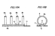
- Figs. 9, 10A and 10B show the state where the ring binder 8 is coupled with the back plate 11.
- the hooks 12 of the back plate 11 are forcibly expanded by the ring segments 8b of the ring binder 8.
- the ring segments 8b each is sandwiched and engaged vertically from both sides by the hooks 12 so that the ring binder 8 and the back plate 11 are coupled with each other.
- a back plate 21 shown in Fig. 11 is provided with bind tabs 22 in place of the hooks as the coupling means for the ring binder.
- the bind tabs 22 laterally protrude from an upper position, vertically intermediate position and lower position of the one side of the back plate 21.
- hooks 23 are formed, respectively.
- groove holes 24 each constituting a fitting pair with the hook 23 of the bind tab 22 are formed.
- Figs. 12A shows a section taken in line A-A in Fig. 11.
- grooves 25 in which the spine segment of the ring binder 8 is fit are formed. As shown in Figs. 12A and 12B, if the bind tabs 22 are bent by 180 ° so that the hooks 23 of the bind tabs 22 are inserted into the groove holes 24, the hooks 23 are engaged in the groove holes 24. Thus, the bind tabs 22 are fixed in a folded state.
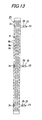
- Fig. 13 shows the state where the ring binder 8 is placed on the back plate 21. As shown in Fig. 13, each bind tab 22 is arranged so that it is located between the ring segments 8b of the ring binder 8.
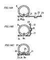
- Figs. 14A to 14C show the procedure of coupling the ring binder 8 and the back plate 21 with each other.
- the spine segment 8a of the ring binder 8 is oppositely placed on the ring receiving portion of the back plate 21.
- the bind tabs 22 are bent toward the back plate.
- the spine segment 8b of the ring binder 8 is fit in the grooves 25 of the bind tubs 22.
- the hooks 23 of the bind tabs 22 are engaged in the groove holes 24 of the back plate 21.
- the ring binder 8 is fixed in the state where the bind tabs 21 are fixed in the folded state.
- the booklet previously bound with the ring binder can be attached to the back plate 21 in such a manner that as shown in Fig. 15, the booklet B pushed over sideways by causing the bind tabs 22 to stand up is moved down from above so that the bind tabs 22 pass through the gap between the spine segment 8a of the ring binder 8 and the back of the booklet B.
- the back plates are used in a state attached to the file cover.
- the back plate may be used as a single body.
- the spine (surface) of the back plate in a flat shape with no opening, affixing a seal filled with a file name on the spine surface, directly entering the file name, the retrieval of the booklet is facilitated.
- a T-shape groove 32 may be formed on the spine of the back plate 31 and a file name plate 33 having a T-shape section and filled with a file name may be engaged in the T-shape groove 32.
- a back plate is preferably used when the booklet B is housed vertically in a file case with the spine of the booklet B being oriented upward.
- the back plate serving as the spine of the booklet is formed detachably from the ring binder, by attaching the back plate to the ring binder binding the booklet and entering e.g. a file name on the back plate, the retrieval of the booklet is facilitated.
- the back plate has an effect of restraining the warp of the booklet and ring binder. Further, by firmly integrating the back plate to the spine surface of the file cover, the file cover can be attached to or detached from the booklet as required.
- the back plate serving as the spine of the booklet is provided with the engagement means such as hooks, the back plate is made detachable from the ring binder.
- the back plate may be mounted in the ring binder as a single body. Further, by fixing the back plate inside the spine surface of the file cover, the file cover can be easily mounted on the booklet bound with the ring binder.
Landscapes
- Sheet Holders (AREA)
Abstract
Description
- The invention relates to a filing tool, and more particularly to a back plate and a file cover detachable from a ring binder.
- As a filing tool for binding documents punched by a multi-hole punching device or commercially available loose leaf sheets, there has been conventionally and widely used a filing binder in which metal or resin foldable ring binder is fixed to an inside of a spine surface of a file cover with a front surface, the spine surface and a rear surface.
- Further, there are various shapes of single-body ring binders with no file covers. Among the single-body ring binders, there is a ring binder having comb-like resin strips in a planar shape which are bent cylindrically so that comb teeth are ring-shaped (for example,
JP-A-2001-018571 - Further, as ring binders permitting easier mounting, there is a resin ring binder in which 1/2 ring portions are arranged on both sides of a slender spine portion, and the 1/2 ring portions constituting pairs across the spine portion are closed in a ring shape so that their tips are fit to each other, thereby binding the sheets (
JP-A-2000-289376 JP-A-2003-320779 - The resin ring binder with no the file cover is light in weight and large in the sheet spreading angle so that it is a simple and convenient filing tool. However, since it is not accompanied by the spine surface, when the booklets bound with the ring binder are arranged or stacked on a bookshelf, the filing name of each booklet is difficult to know, and the entire booklet is likely to warp. For the reason, in order to bind the document with high importance or frequent use, the binder equipped with the file cover is employed. However, if a cover is required for the booklet once bound with the ring binder, work of removing the booklet from the ring binder and transferring it into the binder equipped with the cover must be executed. The work requires time and labor.
- An object of the invention is to provide a back plate for ring binder which permits a file cover to be attached to or detached from a ring binder according to the use or purpose of a booklet, thereby improving convenience, and the file cover for the ring binder.
- In order to attain the above object, an embodiment of the invention provides a back plate to be mounted on a ring binder having ring segments arranged on a spine segment, which is the back plate for a ring binder, comprising an engaging means for the ring binder, which is formed on the one surface of the back plate so that it is detachable from the ring binder.
- Further, an embodiment of the invention provides a back plate for a ring binder, wherein the engaging means is flexible hooks, and the hooks are engaged with the spine segment or ring segments of the ring binder so that the ring binder and the back plate are coupled with each other.
- An embodiment of the invention provides a back plate for a ring binder, wherein flexible bind tabs each protruding sideward from the side of the back plate is provided; hooks are formed at the tips of the bind tabs; engagement grooves are also formed in which the hooks are fit when the bind tabs are folded toward the back plate; and the bind tabs are folded to be hung over the spine segment of the ring binder so that the hooks are fit in the engagement grooves, thereby coupling the ring binder and back plate with each other.
- Further, an embodiment of the invention provides a file cover for a ring binder, wherein the back plate is mounted on the spine surface of the file cover serving as the surface of a booklet so that the file cover is detachable from the ring binder.
-
- Fig. 1A is a front view of a back plate according to a first embodiment of the invention.
- Fig. 1B is a right side view of the back plate according to the first embodiment.
- Fig. 1C is a lower side view of the back plate according to the first embodiment.
- Fig. 2A is a sectional view taken in arrow line A-A in Fig. 1A.
- Fig. 2B is a sectional view taken in arrow line B-B in Fig. 1A.
- Fig. 2C is a sectional view taken in arrow line C-C in Fig. 1A.
- Fig. 3A is a front view of the state where the back plate according to the first embodiment is attached to a file cover.
- Fig. 3B is a side view of the state where the back plate according to the first embodiment is attached to a file cover.
- Fig. 4 is a view for explaining the procedure of attaching the ring binder to the back plate according to the first embodiment.
- Fig. 5A is a sectional view taken in arrow line A-A in Fig. 1A showing the state where the back plate according to the first embodiment is attached to a file cover.
- Fig. 5B is a sectional view taken in arrow line B-B in Fig. 1A showing the state where the back plate according to the first embodiment is attached to a file cover.
- Fig. 5C is a sectional view taken in arrow line C-C in Fig. 1A showing the state where the back plate according to the first embodiment is attached to a file cover.
- Fig. 6 is a view showing the state where a ring binder and a booklet are attached to the back plate equipped with the file cover.
- Fig. 7A is a front view of a back plate according to a second embodiment.
- Fig. 7B is a right side view of the back plate according to the second embodiment.
- Fig. 7C is a lower side view of the back plate according to the second embodiment.
- Fig. 8A is a sectional view taken in arrow line A-A in Fig. 7A.
- Fig. 8B is a sectional view taken in arrow line B-B in Fig. 7A.
- Fig. 8C is a sectional view taken in arrow line C-C in Fig. 7A.
- Fig. 9 is a plan view of the state where a ring binder is coupled with the back plate according to the second embodiment.
- Fig. 10A is a side sectional view of the state where a ring binder is coupled with the back plate according to the second embodiment.
- Fig. 10B is a front sectional view of the state where a ring binder is coupled with the back plate according to the second embodiment.
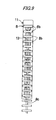
- Fig. 11 is a front view of the back plate according to the third embodiment.
- Fig. 12A is a sectional view taken arrow line A-A in Fig. 11, showing a bind tab before bent.
- Fig. 12B is a sectional view taken arrow line A-A in Fig. 11, showing the bind tab after bent by 90 °.
- Fig. 12C is a sectional view taken arrow line A-A in Fig. 11, showing the bind tab after bent by 180 °.
- Fig. 13 is a plan view of the state where a ring binder is placed on the back plate according to a third embodiment.
- Fig. 14A is a view for explaining the procedure of attaching a ring binder to the back plate according to the third embodiment, which shows the status before the bind tab is bent.
- Fig. 14B is a view for explaining the procedure of attaching the ring binder to the back plate according to the third embodiment, which shows the status after the bind tab has been bent by 90 °.
- Fig. 14C is a view for explaining the procedure of attaching the ring binder to the back plate according to the third embodiment, which shows the status after the bind tab has been bent by 180 °.
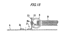
- Fig. 15 is a view for explaining the procedure of attaching the back plate according to the third embodiment to a booklet bound with the ring binder.
- Fig. 16 is a view for explaining the procedure of attaching the ring binder to the back plate according to a fourth embodiment.
- Fig. 17 is a sectional view of the back plate and a file name plate according to the fourth embodiment.
- In the drawings,
reference numeral 1 denotes a back plate; 2 a positioning convex portion; 3 a ring-receiving portion; 4 a spine-receiving portion; 5 a hook; 6 a file cover; 8 a ring binder; 8a a spine segment; 8b a ring segment, 11 a back plate; 12 a hook; 13 a ring-receiving portion; 21 a back plate; 22 a bind tab; 23 a hook; 24 a groove hole, 25 a groove; 26 a ring-receiving portion; 31 a back plate; 32 a T groove; and 33 a file name plate. - Embodiments of the invention will be described with reference to the accompanying drawings.
- Figs. 1A to 1C show a
back plate 1 mountable in a ring binder. A V-shapedring receiving portion 3 is formed betweenconvexes 2 made in the vicinity of the upper and lower ends on the front. In thering receiving portion 3, concave-groovespine receiving segments 4 for receiving the spine of the ring binder and hooks 5 to be engaged with the spine of the ring binder are formed at regular intervals. Figs. 2A, 2B and 2C show sections taken in lines A-A, B-B and C-C in Fig. 1A, respectively. Thehooks 5 are oppositely arranged left and right across a laterally center line of theback plate 1. Thehooks 5 are engaged onto the upper face of the spine of the ring binder inserted between theopposite hooks 5, thereby holding the spine. - Figs. 3A and 3B show the state where the
back plate 1 is mounted inside the spine surface of afile cover 6 made of resin or thick paper. Theback plate 1 may be coupled with thefile cover 6 by means of grommetting or riveting usingcircular holes 7 formed in the vicinity of both upper and lower ends, or otherwise may be coupled with thefile cover 6 by means of bonding or welding. The coupling means should not be particularly limited. - Fig. 4 shows the procedure for coupling the
ring binder 8 and theback plate 1. With a booklet B bound with thering binder 8 being held by a hand, the spine segment of thering binder 8 is pressed against theback plate 1 so as to be opposed to thering receiving portion 3 of theback plate 1. Thehooks 5 of theback plate 1 are forcibly expanded by the spine segment of thering binder 8. Thus,- as shown in Fig. 5A, thehooks 5 sandwiches thespine segment 8a from both left and right sides so that thering binder 8 and theback plate 1 are coupled with each other. Figs. 5A, 5B and 5C are sectional views corresponding to Figs. 2A, 2B and 2C. As shown in Fig. 5B, thespine segment 8a of thering binder 8 is engaged in and supported by the concave-groove of thespine receiving segment 4. As shown in Fig. 5C, thering segments 8b of thering binder 8 are placed on and supported by thering receiving portion 3. - Fig. 6 shows the state where the
file cover 6 is mounted on the booklet B bound with thering binder 8 through theback plate 1. It is needless to say that on the spine surface or front surface of thefile cover 6, a file name and other matters can be indicated or a seal can be affixed. Thus, from the indication on the spine surface, the file name of the booklet can be known when the booklet is housed or stacked on a bookshelf. - Figs. 7A to 7C show a
back plate 11 according to a second embodiment. In theback plate 11 according to the second embodiment, the direction of hooks is different from that in theback plate 1 according to the first embodiment. The tips ofhooks 12 vertically making pairs are opposite to each other. Figs. 8A, 8B and 8C shows section taken in lines A-A, B-B and C-C in Fig. 7A, respectively. Figs. 9, 10A and 10B show the state where thering binder 8 is coupled with theback plate 11. If the spine segments of thering binder 8 are pressed against theback plate 11 so as to be opposite to thering receiving portion 13 of theback plate 11, thehooks 12 of theback plate 11 are forcibly expanded by thering segments 8b of thering binder 8. Thus, as shown in Figs. 10A and 10B, thering segments 8b each is sandwiched and engaged vertically from both sides by thehooks 12 so that thering binder 8 and theback plate 11 are coupled with each other. - A
back plate 21 shown in Fig. 11 is provided withbind tabs 22 in place of the hooks as the coupling means for the ring binder. Thebind tabs 22 laterally protrude from an upper position, vertically intermediate position and lower position of the one side of theback plate 21. At the tips of thebind tabs 22, hooks 23 are formed, respectively. At the edges of theback plate 21 on a side opposite to the side where the bind tabs are attached, groove holes 24 each constituting a fitting pair with thehook 23 of thebind tab 22 are formed. Figs. 12A shows a section taken in line A-A in Fig. 11. - At the laterally intermediate positions of the
bind tabs 22,grooves 25 in which the spine segment of thering binder 8 is fit are formed. As shown in Figs. 12A and 12B, if thebind tabs 22 are bent by 180 ° so that thehooks 23 of thebind tabs 22 are inserted into the groove holes 24, thehooks 23 are engaged in the groove holes 24. Thus, thebind tabs 22 are fixed in a folded state. - Fig. 13 shows the state where the
ring binder 8 is placed on theback plate 21. As shown in Fig. 13, eachbind tab 22 is arranged so that it is located between thering segments 8b of thering binder 8. - Figs. 14A to 14C show the procedure of coupling the
ring binder 8 and theback plate 21 with each other. As shown in Fig. 14A, thespine segment 8a of thering binder 8 is oppositely placed on the ring receiving portion of theback plate 21. As shown in Fig. 14B, thebind tabs 22 are bent toward the back plate. Further, as shown in Fig. 14C, if thehooks 23 of thebind tabs 22 are inserted into the groove holes 24, respectively, thespine segment 8b of thering binder 8 is fit in thegrooves 25 of thebind tubs 22. In addition, thehooks 23 of thebind tabs 22 are engaged in the groove holes 24 of theback plate 21. Thus, thering binder 8 is fixed in the state where thebind tabs 21 are fixed in the folded state. - Incidentally, the booklet previously bound with the ring binder can be attached to the
back plate 21 in such a manner that as shown in Fig. 15, the booklet B pushed over sideways by causing thebind tabs 22 to stand up is moved down from above so that thebind tabs 22 pass through the gap between thespine segment 8a of thering binder 8 and the back of the booklet B. - In the first to third embodiments, the back plates are used in a state attached to the file cover. However, the back plate may be used as a single body. In the case, by making the spine (surface) of the back plate in a flat shape with no opening, affixing a seal filled with a file name on the spine surface, directly entering the file name, the retrieval of the booklet is facilitated.
- Further, as shown in Figs. 16 and 17, a T-
shape groove 32 may be formed on the spine of theback plate 31 and afile name plate 33 having a T-shape section and filled with a file name may be engaged in the T-shape groove 32. Such a back plate is preferably used when the booklet B is housed vertically in a file case with the spine of the booklet B being oriented upward. - It will be apparent that the invention should not be limited to the embodiments described above, but may be modified in various manners within a technical scope of the invention and covers these modifications.
- The application is based on
Japanese Patent Application No. 2004-074853 filed on March 16, 2004 - In the embodiments of the invention, since the back plate serving as the spine of the booklet is formed detachably from the ring binder, by attaching the back plate to the ring binder binding the booklet and entering e.g. a file name on the back plate, the retrieval of the booklet is facilitated. The back plate has an effect of restraining the warp of the booklet and ring binder. Further, by firmly integrating the back plate to the spine surface of the file cover, the file cover can be attached to or detached from the booklet as required.
- In the embodiments of the invention, since the back plate serving as the spine of the booklet is provided with the engagement means such as hooks, the back plate is made detachable from the ring binder. The back plate may be mounted in the ring binder as a single body. Further, by fixing the back plate inside the spine surface of the file cover, the file cover can be easily mounted on the booklet bound with the ring binder.
Claims (5)
- A back plate for a ring binder, to which a ring binder including a spine segment and a ring segment is detachably mounted, comprising:an engaging means formed on one surface of the back plate to be engaged with the ring binder.
- The back plate for a ring binder according to claim 1, wherein the engaging means comprises a flexible hook, and
the hook is engaged with the spine segment of the ring binder so that the ring binder and the back plate are coupled with each other. - The back plate for a ring binder according to claim 1, wherein the engaging means comprises a flexible hook, and
the hook is engaged with the ring segment of the ring binder so that the ring binder and the back plate are coupled with each other. - The back plate for a ring binder according to claim 1, wherein the engaging means comprises:a bind tab protruding sideward from a side of the back plate;a hook formed at a tip of the bind tab; andan engagement groove to which the hook is engaged when the bind tab is folded toward the back plate, andwherein the bind tab is folded to be hung over the spine segment of the ring binder, and the hook is fit in the engagement groove so that the ring binder and the back plate are coupled with each other.
- A file cover for a ring binder, comprising:a spine surface, wherein the back plate according to claim 1 is mounted on the spine surface.
Applications Claiming Priority (2)
| Application Number | Priority Date | Filing Date | Title |
|---|---|---|---|
| JP2004074853A JP4442266B2 (en) | 2004-03-16 | 2004-03-16 | Back plate and file cover for ring binder |
| PCT/JP2005/005046 WO2005087508A1 (en) | 2004-03-16 | 2005-03-15 | Back plate for ring binder, and file cover |
Publications (3)
| Publication Number | Publication Date |
|---|---|
| EP1726453A1 true EP1726453A1 (en) | 2006-11-29 |
| EP1726453A4 EP1726453A4 (en) | 2011-01-12 |
| EP1726453B1 EP1726453B1 (en) | 2012-12-19 |
Family
ID=34975433
Family Applications (1)
| Application Number | Title | Priority Date | Filing Date |
|---|---|---|---|
| EP05721196A Ceased EP1726453B1 (en) | 2004-03-16 | 2005-03-15 | Ring binder with a back plate and file cover |
Country Status (7)
| Country | Link |
|---|---|
| US (1) | US7665924B2 (en) |
| EP (1) | EP1726453B1 (en) |
| JP (1) | JP4442266B2 (en) |
| KR (1) | KR101202513B1 (en) |
| CN (1) | CN100439121C (en) |
| TW (1) | TWI277541B (en) |
| WO (1) | WO2005087508A1 (en) |
Cited By (2)
| Publication number | Priority date | Publication date | Assignee | Title |
|---|---|---|---|---|
| WO2012001204A1 (en) * | 2010-06-30 | 2012-01-05 | Artes Graficas De Yecla, S.L. | Assembly for securing a cover to a double spiral notebook |
| CN103072399A (en) * | 2011-10-04 | 2013-05-01 | 斯特普尔斯办公用品超市有限公司 | Binder with detachable article holder |
Families Citing this family (8)
| Publication number | Priority date | Publication date | Assignee | Title |
|---|---|---|---|---|
| KR100891749B1 (en) * | 2007-07-11 | 2009-04-03 | 박철우 | File for Spring Binder |
| BE1018555A3 (en) * | 2009-07-30 | 2011-03-01 | Unibind Ltd | ELEMENT FOR MANUFACTURING A PRESENTATIVE. |
| US20120082504A1 (en) * | 2010-10-01 | 2012-04-05 | Sheng-Tan Wang | Loose-leaf binder |
| US20120261460A1 (en) * | 2011-04-13 | 2012-10-18 | Smart Fortune International Limited | File folder |
| JP5823236B2 (en) * | 2011-10-05 | 2015-11-25 | 株式会社キングジム | Booklet cover and booklet with booklet cover |
| CN103231597A (en) * | 2013-04-22 | 2013-08-07 | 陈恩柔 | Coil notebook cover clip |
| JP6886687B2 (en) * | 2017-03-08 | 2021-06-16 | 株式会社カネダ技研 | Ring-type binding holder, holder with binding, and files |
| KR102248925B1 (en) | 2020-04-09 | 2021-05-07 | 원용길 | two-pocket document folder |
Family Cites Families (53)
| Publication number | Priority date | Publication date | Assignee | Title |
|---|---|---|---|---|
| US491473A (en) * | 1893-02-07 | Temporary binder for file-cases | ||
| US1074510A (en) * | 1913-03-29 | 1913-09-30 | Peter Macmaster | Renewable-leaf book. |
| US1466313A (en) * | 1921-04-07 | 1923-08-28 | Nat Blank Book Co | Loose-leaf binder |
| US1745461A (en) * | 1926-04-08 | 1930-02-04 | Trussell Mfg Co | Book cover and method of making same |
| US2156232A (en) * | 1937-10-25 | 1939-04-25 | Trussell Mfg Co | Binder |
| US2243535A (en) * | 1938-09-15 | 1941-05-27 | Wilson Jones Co | Loose-leaf binder |
| US2325155A (en) * | 1941-05-16 | 1943-07-27 | Wilson Jones Co | Loose-leaf binder |
| US2262601A (en) * | 1941-06-06 | 1941-11-11 | Arthur F Brook | Book |
| US2888934A (en) * | 1957-05-29 | 1959-06-02 | Wilson Jones Co | Loose leaf binder |
| US3252461A (en) * | 1964-04-06 | 1966-05-24 | Nat Blank Book Co | Loose leaf binder construction |
| GB1153728A (en) * | 1966-01-14 | 1969-05-29 | C H Hare & Son Ltd | Improvements relating to Loose-Leaf Binders |
| US3351065A (en) * | 1966-04-21 | 1967-11-07 | Roush John Herbert | Loose leaf binder structure |
| JPS4827023A (en) | 1971-08-13 | 1973-04-10 | ||
| JPS5346215U (en) * | 1976-09-25 | 1978-04-19 | ||
| JPS5346215A (en) | 1976-10-08 | 1978-04-25 | Kondo Seisakushiyo Kk | Channel selector for transceiver |
| US4120517A (en) * | 1977-06-21 | 1978-10-17 | General Binding Corporation | Removable plastic binding |
| US4400107A (en) * | 1981-01-29 | 1983-08-23 | Dennison Manufacturing Company | Suspension files and binders |
| JPS61138579A (en) | 1984-12-11 | 1986-06-26 | 株式会社 平林 | Rough washer |
| US4607970A (en) * | 1985-02-05 | 1986-08-26 | Ted Scudder | Binder for perforated sheets |
| US4750884A (en) | 1985-08-09 | 1988-06-14 | American Trading And Production Corporation | Binder backing for notebooks |
| US4765768A (en) * | 1987-08-24 | 1988-08-23 | Wright John S | Ring binding mechanism |
| JPH0197979A (en) | 1987-10-09 | 1989-04-17 | Fujitsu Ltd | Recorder |
| GB8823414D0 (en) * | 1988-10-05 | 1988-11-09 | Benson International Systems L | Binder mechanism |
| US4941804A (en) * | 1989-04-27 | 1990-07-17 | Sarpy Jr John B | Plastic multi-ring paper binding system using one piece cover |
| JPH0349235A (en) | 1989-07-18 | 1991-03-04 | Fuji Xerox Co Ltd | Manufacture of mos-type semiconductor device |
| US5037229A (en) * | 1990-01-22 | 1991-08-06 | Creative Binding Systems, Inc. | Closure for wire loop binder |
| US5394332A (en) * | 1991-03-18 | 1995-02-28 | Pioneer Electronic Corporation | On-board navigation system having audible tone indicating remaining distance or time in a trip |
| DE4126327A1 (en) * | 1991-08-08 | 1993-02-11 | Hugo Bippus | Brochure with wire binding - which is formed into loops which grip rail of special cross=section fastened to cover |
| JP3194623B2 (en) | 1992-07-06 | 2001-07-30 | 松下電器産業株式会社 | Small wireless receiver |
| US5348412A (en) * | 1992-09-29 | 1994-09-20 | U.S. Ring Binder | Releasable attachment for a ring metal to a ring binder |
| AT662U1 (en) * | 1995-02-10 | 1996-03-25 | Koloman Handler Gmbh | DEVICE FOR FIXING A HOLDING MECHANICAL |
| US5988926A (en) * | 1995-05-22 | 1999-11-23 | Kokuyo Co., Ltd. | Filing device |
| ATE192705T1 (en) * | 1996-06-19 | 2000-05-15 | Juergen Vogel | FILE FOLDER WITH MODULAR STRUCTURE |
| JPH1178338A (en) * | 1997-09-12 | 1999-03-23 | Aosan:Kk | Openable binder |
| JPH11151885A (en) * | 1997-11-21 | 1999-06-08 | Kokuyo Co Ltd | Binding tool |
| US6010270A (en) * | 1998-02-17 | 2000-01-04 | Michael N. Friedman | Ring binder with locking device |
| JP3049235B2 (en) | 1998-11-17 | 2000-06-05 | 松下電器産業株式会社 | Speech recognition system using complex grammar network |
| JP2000289376A (en) | 1999-03-31 | 2000-10-17 | Ibico Trading Gmbh | Binder for fixing back part |
| US6155737A (en) * | 1999-04-30 | 2000-12-05 | U. S. Ring Binder Corporation | Bolt action ring binder |
| JP2001018571A (en) | 1999-07-09 | 2001-01-23 | Carl Manufacturing Co Ltd | Paper spelling machine |
| US20030210228A1 (en) * | 2000-02-25 | 2003-11-13 | Ebersole John Franklin | Augmented reality situational awareness system and method |
| JP3681952B2 (en) * | 2000-04-03 | 2005-08-10 | 三菱電機株式会社 | DSRC OBE |
| CN2444772Y (en) * | 2000-10-12 | 2001-08-29 | 北京市康得机电发展总公司 | Plastic-ring button |
| JP2002192872A (en) * | 2000-10-19 | 2002-07-10 | Tomoda Giken Kogyo Kk | Filing implement |
| CN2470121Y (en) * | 2001-02-27 | 2002-01-09 | 叶壮图 | Improvement of the hook device of the binder |
| US6778073B2 (en) * | 2001-06-26 | 2004-08-17 | Medius, Inc. | Method and apparatus for managing audio devices |
| CA2378253A1 (en) * | 2002-03-22 | 2003-09-22 | Your Everyday Stationery Ind. Co., Ltd. | Folder apparatus |
| JP4300748B2 (en) | 2002-04-30 | 2009-07-22 | マックス株式会社 | binder |
| JP4132962B2 (en) * | 2002-05-16 | 2008-08-13 | パイオニア株式会社 | Interactive information providing apparatus, interactive information providing program, and storage medium storing the same |
| CN2579669Y (en) * | 2002-11-29 | 2003-10-15 | 吕豪文 | US back case |
| US7190946B2 (en) * | 2002-12-05 | 2007-03-13 | General Motors Corporation | In-vehicle clock synchronization with local time |
| WO2004061394A1 (en) * | 2002-12-27 | 2004-07-22 | Matsushita Electric Industrial Co., Ltd. | Traffic information providing system, traffic information expression method and device |
| US7341390B2 (en) * | 2004-05-05 | 2008-03-11 | Sun L Chang | Loose-leaf binder |
-
2004
- 2004-03-16 JP JP2004074853A patent/JP4442266B2/en not_active Expired - Fee Related
-
2005
- 2005-03-15 WO PCT/JP2005/005046 patent/WO2005087508A1/en not_active Ceased
- 2005-03-15 CN CNB2005800086995A patent/CN100439121C/en not_active Expired - Fee Related
- 2005-03-15 EP EP05721196A patent/EP1726453B1/en not_active Ceased
- 2005-03-15 KR KR1020067018822A patent/KR101202513B1/en not_active Expired - Fee Related
- 2005-03-15 US US10/592,321 patent/US7665924B2/en not_active Expired - Fee Related
- 2005-03-15 TW TW094107837A patent/TWI277541B/en not_active IP Right Cessation
Cited By (3)
| Publication number | Priority date | Publication date | Assignee | Title |
|---|---|---|---|---|
| WO2012001204A1 (en) * | 2010-06-30 | 2012-01-05 | Artes Graficas De Yecla, S.L. | Assembly for securing a cover to a double spiral notebook |
| CN103072399A (en) * | 2011-10-04 | 2013-05-01 | 斯特普尔斯办公用品超市有限公司 | Binder with detachable article holder |
| EP2578415A3 (en) * | 2011-10-04 | 2016-01-06 | Staples The Office Superstore, LLC | Binder with removable article holder, article holder and method of detaching them |
Also Published As
| Publication number | Publication date |
|---|---|
| US20070196162A1 (en) | 2007-08-23 |
| US7665924B2 (en) | 2010-02-23 |
| JP4442266B2 (en) | 2010-03-31 |
| CN100439121C (en) | 2008-12-03 |
| KR101202513B1 (en) | 2012-11-16 |
| CN1933982A (en) | 2007-03-21 |
| EP1726453B1 (en) | 2012-12-19 |
| JP2005262495A (en) | 2005-09-29 |
| TW200531848A (en) | 2005-10-01 |
| TWI277541B (en) | 2007-04-01 |
| EP1726453A4 (en) | 2011-01-12 |
| KR20060132721A (en) | 2006-12-21 |
| WO2005087508A1 (en) | 2005-09-22 |
Similar Documents
| Publication | Publication Date | Title |
|---|---|---|
| EP2808174A2 (en) | Media binder systems with datum stops for registering physical media sheets | |
| US7665924B2 (en) | Back plate and file cover for ring binder | |
| EP1199188A2 (en) | Filing device. | |
| US7052045B2 (en) | Labeling device for bound materials | |
| CN101152814A (en) | Binding tool body for folder and folder capable of adjusting back cover amplitude | |
| JPH09142077A (en) | Attaching structure for paper filing tool | |
| JP3609899B2 (en) | Case file | |
| JP4041562B2 (en) | Stop and file with this stop | |
| JP3983008B2 (en) | File | |
| EP1426199A1 (en) | Spine-indexing device | |
| JP4674669B2 (en) | Booklet composition and booklet | |
| KR910004170Y1 (en) | Loose-leaf filing device | |
| JPH11208173A (en) | Filing device and supporting implement | |
| JP2003341270A (en) | File stationery | |
| JP3076036U (en) | Refill with bindings | |
| JP2004168017A (en) | Binder writable using cover as underlay | |
| JP3144863U (en) | Binding assist device | |
| JP3125291U (en) | Reading tools | |
| JP2602255Y2 (en) | binder | |
| JPH11216982A (en) | Binder | |
| JP2000141970A (en) | Holder | |
| KR200180542Y1 (en) | Spin-width adjustable self-adhesive book cover | |
| JP3041866U (en) | Loose leaf-shaped note | |
| JP2002127658A (en) | Filing device | |
| EP0540349A1 (en) | Paper binder system |
Legal Events
| Date | Code | Title | Description |
|---|---|---|---|
| PUAI | Public reference made under article 153(3) epc to a published international application that has entered the european phase |
Free format text: ORIGINAL CODE: 0009012 |
|
| 17P | Request for examination filed |
Effective date: 20060911 |
|
| AK | Designated contracting states |
Kind code of ref document: A1 Designated state(s): DE FR GB NL SE |
|
| DAX | Request for extension of the european patent (deleted) | ||
| RBV | Designated contracting states (corrected) |
Designated state(s): DE FR GB NL SE |
|
| A4 | Supplementary search report drawn up and despatched |
Effective date: 20101214 |
|
| 17Q | First examination report despatched |
Effective date: 20111018 |
|
| REG | Reference to a national code |
Ref country code: DE Ref legal event code: R079 Ref document number: 602005037482 Country of ref document: DE Free format text: PREVIOUS MAIN CLASS: B42F0013160000 Ipc: B42F0013000000 |
|
| GRAP | Despatch of communication of intention to grant a patent |
Free format text: ORIGINAL CODE: EPIDOSNIGR1 |
|
| RIC1 | Information provided on ipc code assigned before grant |
Ipc: B42F 13/00 20060101AFI20120627BHEP |
|
| GRAS | Grant fee paid |
Free format text: ORIGINAL CODE: EPIDOSNIGR3 |
|
| GRAA | (expected) grant |
Free format text: ORIGINAL CODE: 0009210 |
|
| AK | Designated contracting states |
Kind code of ref document: B1 Designated state(s): DE FR GB NL SE |
|
| REG | Reference to a national code |
Ref country code: GB Ref legal event code: FG4D |
|
| REG | Reference to a national code |
Ref country code: DE Ref legal event code: R096 Ref document number: 602005037482 Country of ref document: DE Effective date: 20130214 |
|
| REG | Reference to a national code |
Ref country code: SE Ref legal event code: TRGR |
|
| REG | Reference to a national code |
Ref country code: NL Ref legal event code: VDEP Effective date: 20121219 |
|
| PG25 | Lapsed in a contracting state [announced via postgrant information from national office to epo] |
Ref country code: NL Free format text: LAPSE BECAUSE OF FAILURE TO SUBMIT A TRANSLATION OF THE DESCRIPTION OR TO PAY THE FEE WITHIN THE PRESCRIBED TIME-LIMIT Effective date: 20121219 |
|
| PLBE | No opposition filed within time limit |
Free format text: ORIGINAL CODE: 0009261 |
|
| STAA | Information on the status of an ep patent application or granted ep patent |
Free format text: STATUS: NO OPPOSITION FILED WITHIN TIME LIMIT |
|
| 26N | No opposition filed |
Effective date: 20130920 |
|
| REG | Reference to a national code |
Ref country code: DE Ref legal event code: R097 Ref document number: 602005037482 Country of ref document: DE Effective date: 20130920 |
|
| REG | Reference to a national code |
Ref country code: FR Ref legal event code: PLFP Year of fee payment: 12 |
|
| REG | Reference to a national code |
Ref country code: FR Ref legal event code: PLFP Year of fee payment: 13 |
|
| PGFP | Annual fee paid to national office [announced via postgrant information from national office to epo] |
Ref country code: SE Payment date: 20170313 Year of fee payment: 13 |
|
| REG | Reference to a national code |
Ref country code: FR Ref legal event code: PLFP Year of fee payment: 14 |
|
| PGFP | Annual fee paid to national office [announced via postgrant information from national office to epo] |
Ref country code: GB Payment date: 20180314 Year of fee payment: 14 Ref country code: DE Payment date: 20180227 Year of fee payment: 14 |
|
| PGFP | Annual fee paid to national office [announced via postgrant information from national office to epo] |
Ref country code: FR Payment date: 20180223 Year of fee payment: 14 |
|
| PG25 | Lapsed in a contracting state [announced via postgrant information from national office to epo] |
Ref country code: SE Free format text: LAPSE BECAUSE OF NON-PAYMENT OF DUE FEES Effective date: 20180316 |
|
| REG | Reference to a national code |
Ref country code: DE Ref legal event code: R119 Ref document number: 602005037482 Country of ref document: DE |
|
| GBPC | Gb: european patent ceased through non-payment of renewal fee |
Effective date: 20190315 |
|
| PG25 | Lapsed in a contracting state [announced via postgrant information from national office to epo] |
Ref country code: DE Free format text: LAPSE BECAUSE OF NON-PAYMENT OF DUE FEES Effective date: 20191001 Ref country code: GB Free format text: LAPSE BECAUSE OF NON-PAYMENT OF DUE FEES Effective date: 20190315 |
|
| PG25 | Lapsed in a contracting state [announced via postgrant information from national office to epo] |
Ref country code: FR Free format text: LAPSE BECAUSE OF NON-PAYMENT OF DUE FEES Effective date: 20190331 |