EP1726131B1 - Enhanced uplink dedicated channel - application protocol over iub/iur - Google Patents
Enhanced uplink dedicated channel - application protocol over iub/iur Download PDFInfo
- Publication number
- EP1726131B1 EP1726131B1 EP05708692.8A EP05708692A EP1726131B1 EP 1726131 B1 EP1726131 B1 EP 1726131B1 EP 05708692 A EP05708692 A EP 05708692A EP 1726131 B1 EP1726131 B1 EP 1726131B1
- Authority
- EP
- European Patent Office
- Prior art keywords
- node
- user equipment
- radio
- specific parameter
- uplink
- Prior art date
- Legal status (The legal status is an assumption and is not a legal conclusion. Google has not performed a legal analysis and makes no representation as to the accuracy of the status listed.)
- Active
Links
- 238000000034 method Methods 0.000 claims description 50
- 230000011664 signaling Effects 0.000 claims description 47
- 230000005540 biological transmission Effects 0.000 claims description 21
- 230000008569 process Effects 0.000 claims description 15
- 238000004590 computer program Methods 0.000 claims description 12
- 238000012546 transfer Methods 0.000 claims description 2
- 101000741965 Homo sapiens Inactive tyrosine-protein kinase PRAG1 Proteins 0.000 description 11
- 102100038659 Inactive tyrosine-protein kinase PRAG1 Human genes 0.000 description 11
- 230000006870 function Effects 0.000 description 8
- 238000004891 communication Methods 0.000 description 6
- 230000004044 response Effects 0.000 description 6
- 238000000638 solvent extraction Methods 0.000 description 6
- 230000008901 benefit Effects 0.000 description 2
- 230000008859 change Effects 0.000 description 2
- 239000002131 composite material Substances 0.000 description 2
- 230000001934 delay Effects 0.000 description 2
- 238000010295 mobile communication Methods 0.000 description 2
- 238000012545 processing Methods 0.000 description 2
- 230000007727 signaling mechanism Effects 0.000 description 2
- 230000003044 adaptive effect Effects 0.000 description 1
- 230000015572 biosynthetic process Effects 0.000 description 1
- 230000008094 contradictory effect Effects 0.000 description 1
- 238000012217 deletion Methods 0.000 description 1
- 230000037430 deletion Effects 0.000 description 1
- 230000006872 improvement Effects 0.000 description 1
- 230000002452 interceptive effect Effects 0.000 description 1
- 230000014759 maintenance of location Effects 0.000 description 1
- 230000001360 synchronised effect Effects 0.000 description 1
Images

Classifications
-
- H—ELECTRICITY
- H04—ELECTRIC COMMUNICATION TECHNIQUE
- H04W—WIRELESS COMMUNICATION NETWORKS
- H04W36/00—Hand-off or reselection arrangements
- H04W36/0005—Control or signalling for completing the hand-off
- H04W36/0055—Transmission or use of information for re-establishing the radio link
-
- H—ELECTRICITY
- H04—ELECTRIC COMMUNICATION TECHNIQUE
- H04W—WIRELESS COMMUNICATION NETWORKS
- H04W72/00—Local resource management
- H04W72/20—Control channels or signalling for resource management
- H04W72/29—Control channels or signalling for resource management between an access point and the access point controlling device
-
- H—ELECTRICITY
- H04—ELECTRIC COMMUNICATION TECHNIQUE
- H04W—WIRELESS COMMUNICATION NETWORKS
- H04W88/00—Devices specially adapted for wireless communication networks, e.g. terminals, base stations or access point devices
- H04W88/02—Terminal devices
-
- H—ELECTRICITY
- H04—ELECTRIC COMMUNICATION TECHNIQUE
- H04W—WIRELESS COMMUNICATION NETWORKS
- H04W88/00—Devices specially adapted for wireless communication networks, e.g. terminals, base stations or access point devices
- H04W88/08—Access point devices
-
- H—ELECTRICITY
- H04—ELECTRIC COMMUNICATION TECHNIQUE
- H04W—WIRELESS COMMUNICATION NETWORKS
- H04W88/00—Devices specially adapted for wireless communication networks, e.g. terminals, base stations or access point devices
- H04W88/12—Access point controller devices
-
- H—ELECTRICITY
- H04—ELECTRIC COMMUNICATION TECHNIQUE
- H04W—WIRELESS COMMUNICATION NETWORKS
- H04W92/00—Interfaces specially adapted for wireless communication networks
- H04W92/04—Interfaces between hierarchically different network devices
- H04W92/045—Interfaces between hierarchically different network devices between access point and backbone network device
-
- H—ELECTRICITY
- H04—ELECTRIC COMMUNICATION TECHNIQUE
- H04W—WIRELESS COMMUNICATION NETWORKS
- H04W72/00—Local resource management
- H04W72/04—Wireless resource allocation
Definitions
- the present invention relates to an enhanced mobile communications uplink (the direction of the radio link from the user equipment to the network) and, more particularly, to the content of messages needed between a third generation a radio network controller (RNC) and base station (Node B) to carry out the enhancement within a mobile communications network.
- RNC radio network controller
- Node B base station
- the study includes the following topics related to enhanced uplink for UTRA FDD (Frequency Division Duplex) to enhance uplink performance in general or to enhance the uplink performance for background, interactive and streaming based traffic:
- This UL E-DCH can be compared to HSDPA (High Speed Downlink Packet Access) since HSDPA was for a similar enhancement in the downlink (DL).
- HSDPA High Speed Downlink Packet Access
- signalling over the interfaces (lub/lur) between the 3GPP radio network controller (RNC) and Node B and between RNCs, including parameters, is shown to support the air interface enhancement on UL DCHs.
- WO 03 100989 A2 describes a method for use by a first entity of a radio access network, such as a node B, in communicating with a UE so as to control an uplink rate used by the UE in communicating with the first entity.
- EP-A-1 041 850 describes a method of operating a telecommunications system in which mobile terminals may communicate with base station transceivers over an air interface, a communication to another user terminal being supported in macrodiversity by radio links between a plurality of base station transceivers and a mobile terminal.
- the radio links in macrodiversity have a set of common radio link configuration parameters.
- the present invention defines the basic Information Elements (IEs), which should be provided to set up and to support E-DCH functionality in the network on lub/lur.
- IEs Information Elements
- the goal of this invention is to provide general signalling methods for the lub/lur interface between the RNCs and the Node Bs in order to be able to setup and re-configure the UL E-DCH channel. It is another object to do so with maximum flexibility so as not to be restricted to any particular message, but to be later applicable to any selected message or messages in the yet undefined protocol.
- a method comprising: receiving information having both a cell specific parameter and a radio link specific parameter, in respective messages on an interface between a Node B and a radio network controller for configuring a radio uplink from a user equipment to the Node B; configuring the radio uplink at the Node B according to at least one of the radio link specific parameter and the cell specific parameter; and receiving a payload packet from the user equipment to the Node B over the radio uplink after the uplink is configured at the Node B, wherein the cell specific parameter comprises an information element indicating the total allowable uplink interference for the Node B, and the radio link specific parameter comprises at least one of an information element indicating the power offset of acknowledgement transmission to the user equipment and an information element indicating the power offset of rate grant signalling to the user equipment.
- the method may further comprise: acknowledging correct reception of the payload packet at the Node B on a radio downlink from the Node B to the user equipment; and sending the payload packet from the Node B to the radio network controller following the correct reception from the user equipment.
- the receiving by the Node B may include receiving at least one parameter indicative of boundaries within which choices may be made by the Node B.
- a method comprising: sending information having both a cell specific parameter and a radio link specific parameter, in respective messages on an interface to a Node B from a radio network controller for configuring a radio uplink from a user equipment to the Node B, wherein the cell specific parameter comprises an information element indicating the total allowable uplink interference for the Node B, and the radio link specific parameter comprises at least one of an information element indicating the power offset of acknowledgement transmission to the user equipment and an information element indicating the power offset of rate grant signalling to the user equipment; and receiving a payload packet from the Node B after the payload packet has been sent from the user equipment to the Node B over the radio uplink that has been configured at the Node B according to at least one of the radio link specific parameter and the cell specific parameter.
- the method may further comprise sending the information on an interface between the radio network controller and another radio network controller for relay to another Node B for configuring an uplink between the other Node B and the user equipment.
- Configuring the uplink between the other Node B and the user equipment may comprise configuring the uplink between the other Node B and the user equipment followed by sending the payload packet from the user equipment to the other Node B over the radio uplink between the user equipment and the other Node B for sending the payload packet to the radio network controller.
- the method may further comprise: acknowledging correct reception of the payload packet at the Node B on a radio downlink from the Node B to the user equipment; and acknowledging correct reception of the payload packet at the other Node B on a radio downlink from the other Node B to the user equipment.
- the radio network controller may decide a value for the cell specific parameter or the radio link specific parameter, or both, for sending the information element with the cell specific parameter and the radio link specific parameter in the one or more messages on the interface from the radio network controller to the Node B.
- the radio network controller may be responsive to signalling from the Node B with a proposed value or values for the cell specific parameter, the radio link specific parameter, or both, and the radio network controller may carry out sending the information element either confirming or changing the proposed value or values.
- the sending by the radio network controller may include sending at least one parameter to the Node B indicative of boundaries within which choices may be made by the Node B.
- a radio network controller comprising: a first interface configured to communicate information having both a cell specific parameter and a radio link specific parameter in respective messages to a Node B from the radio network controller in order to configure a radio uplink from user equipment to the Node B according to at least one of the radio link specific parameter and the cell specific parameter; and a second interface configured to communicate the information between the radio network controller and a second radio network controller connected to a second Node B, wherein the cell specific parameter comprises an information element indicating the total allowable uplink interference for the Node B, and the radio link specific parameter comprises at least one of an information element indicating the power offset of acknowledgement transmission to the user equipment and an information element indicating the power offset of rate grant signalling to the user equipment.
- the information may be arranged to configure a second radio uplink between the second Node B and the user equipment, the radio network controller being configured to receive a payload packet from the Node B over the first interface, the second radio network controller being configured to receive the payload packet from the second Node B after receipt by the second Node B from the user equipment over the second radio uplink, and the second radio network controller being configured to send the payload packet received from the second Node B to the radio network controller following the reception by the second Node B from the user equipment for transfer from the second radio network controller to the radio network controller.
- a Node B comprising: a first means for communicating information having both a cell specific parameter and a radio link specific parameter in respective messages between the Node B and a radio network controller for configuring an uplink channel on a radio link; and a second means for communicating signals related to configuring the uplink channel between the Node B and the user equipment, and arranged to receive a payload packet from the user equipment to the Node B over the radio uplink after configuring the uplink channel on the radio link is carried out by the Node B according to at least one of the radio link specific parameter and the cell specific parameter, wherein the cell specific parameter comprises an information element indicating the total allowable uplink interference for the Node B, and the radio link specific parameter comprises at least one of an information element indicating the power offset of acknowledgement transmission to the user equipment and an information element indicating the power offset of rate grant signalling to the user equipment, and wherein the first means is also for conveying the payload packet from the Node B to the radio network controller following the reception
- the Node B may be arranged to acknowledge reception of the payload packet, on a radio downlink from the Node B to the user equipment.
- the Node B may comprise: a first interface arranged to communicate information having both a cell specific parameter and a radio link specific parameter in respective messages between the Node B and a radio network controller in order to configure an uplink channel on a radio link; and a second interface arranged to communicate signals related to configuring the uplink channel between the Node B and the user equipment, and arranged to receive a payload packet from the user equipment to the Node B over the radio uplink after configuring the uplink channel on the radio link is carried out by the Node B, wherein the first interface is also arranged to convey the payload packet from the Node B to the radio network controller following the reception by the Node B from the user equipment.
- a user equipment comprising: a transceiver configured to receive and transmit signals over an interface between the user equipment and a Node B; and a control arranged to process signalling between the Node B and the user equipment in order to configure a radio uplink from user equipment to a Node B according to at least one of a radio link specific parameter and a cell specific parameter conveyed in information having both the cell specific parameter and the radio link specific parameter in respective messages on an interface between the Node B and a radio network controller, wherein the cell specific parameter comprises an information element indicating the total allowable uplink interference for the Node B, and the radio link specific parameter comprises at least one of an information element indicating the power offset of acknowledgement transmission to the user equipment and an information element indicating the power offset of rate grant signalling to the user equipment, wherein the user equipment is configured to send a payload packet from the user equipment to the Node B over the radio uplink after the uplink is configured.
- a system comprising: a Node B according to the fourth aspect of the present invention and a radio network controller according to the third aspect of the present invention connected by a signalling interface and arranged to configure a radio uplink from a user equipment to the Node B, the interface being arranged to convey messages having information elements that contain parameters and to convey the information having both the cell specific parameter and the radio link specific parameter in the respective messages; and a user equipment arranged to send a payload packet to the Node B over the radio uplink after the uplink is configured at the user equipment for sending the payload packet to the radio network controller.
- a computer program comprising program code means adapted to perform the following when the program is run on a processor: receiving information having both a cell specific parameter and a radio link specific parameter, in respective messages on an interface between a Node B and a radio network controller for configuring a radio uplink from a user equipment to the Node B; configuring the radio uplink at the Node B according to at least one of the radio link specific parameter and the cell specific parameter; and receiving a payload packet from the user equipment to the Node B over the radio uplink after the uplink is configured at the Node B, wherein the cell specific parameter comprises an information element indicating the total allowable uplink interference for the Node B, and the radio link specific parameter comprises at least one of an information element indicating the power offset of acknowledgement transmission to the user equipment and an information element indicating the power offset of rate grant signalling to the user equipment.
- the program code means may be further adapted to perform the following: acknowledging correct reception of the payload packet at the Node B on a radio downlink from the Node B to the user equipment; and sending the payload packet from the Node B to the radio network controller following the correct reception from the user equipment.
- the receiving by the Node B may include receiving at least one parameter indicative of boundaries within which choices may be made by the Node B.
- a computer program comprising program code means adapted to perform the following when the program is run on a processor: sending information having both a cell specific parameter and a radio link specific parameter, in respective messages on an interface to a Node B from a radio network controller for configuring a radio uplink from a user equipment to the Node B, wherein the cell specific parameter comprises an information element indicating the total allowable uplink interference for the Node B, and the radio link specific parameter comprises at least one of an information element indicating the power offset of acknowledgement transmission to the user equipment and an information element indicating the power offset of rate grant signalling to the user equipment; and receiving a payload packet from a Node B after the payload packet has been sent from the user equipment to the Node B over the radio uplink that has been configured according to at least one of the radio link specific parameter and the cell specific parameter.
- the program code means may be further adapted to perform the following: sending the information on an interface between the radio network controller and another radio network controller for relay to another Node B for configuring an uplink between the other Node B and the user equipment.
- Configuring the uplink between the other Node B and the user equipment may comprise configuring the uplink between the other Node B and the user equipment followed by sending the payload packet from the user equipment to the other Node B over the radio uplink between the user equipment and the other Node B for sending the payload packet to the radio network controller.
- the program code means may be further adapted to perform the following: acknowledging correct reception of the payload packet at the Node B on a radio downlink from the Node B to the user equipment; and acknowledging correct reception of the payload packet at the other Node B on a radio downlink from the other Node B to the user equipment.
- the radio network controller may decide a value for the cell specific parameter or the radio link specific parameter, or both, for sending the information element with the cell specific parameter and the radio link specific parameter in the one or more messages on the interface from the radio network controller to the Node B.
- the radio network controller may be responsive to signalling from the Node B with a proposed value or values for the cell specific parameter, the radio link specific parameter, or both, and the radio network controller may carry out sending the information element either confirming or changing the proposed value or values.
- the sending by the radio network controller may include sending at least one parameter to the Node B indicative of boundaries within which choices may be made by the Node B.
- An enhanced uplink dedicated channel is currently proposed in 3GPP standardization committees in order to provide uplink enhancements for Dedicated Transport Channels.
- uplink performance may be enhanced by improved Hybrid ARQ (Automatic Repeat Request) protocols and Node B controlled scheduling.
- Physical layer or higher layer signaling mechanisms may also be provided to support the enhancements.
- An UL E-DCH can be compared to HSDPA (High Speed Downlink Packet Access) since HSDPA was for a similar enhancement in the downlink (DL).
- Fig. 2 shows a payload packet sent from a User Equipment (UE) over an uplink radio interface to a base station (Node B) and from there to a Radio Network Controller (RNC) connected to the Node B by means other than a radio link.
- the RNC replies with a radio link control (RLC) acknowledgment, indicating either success (ACK) or failure (NACK) in receipt of the payload packet.
- RLC radio link control
- ACK success
- NACK failure
- payload is meant information distinct from configuration information such as setup, scheduling or retransmission control signalling, i.e., for use by the user of the user equipment after setup or reconfiguration in an application such as a web page, video, text, etc.
- ACK success
- NACK failure
- payload is meant information distinct from configuration information such as setup, scheduling or retransmission control signalling, i.e., for use by the user of the user equipment after setup or reconfiguration in an application such as a web page, video, text, etc.
- Fig. 3 shows a proposal, according to an enhanced uplink dedicated channel (E-DCH) concept.
- E-DCH enhanced uplink dedicated channel
- One aspect of the improvement is to enhance the uplink by moving the acknowledgement function from the RNC to the Node B.
- the acknowledgement function is a known retransmission control function that is normally controlled at the RNC and need not be described here. What is important here is the network entity selected to perform this function.
- the E-DCH concept helps reduce delays by making the Node B take on control of this important function closer to the UE.
- the E-DCH proposal has not yet explained the information elements and parameters needed to be exchanged in the above-mentioned distinct signalling procedures between an RNC and a Node B, between the Node B and the user equipment, and also between RNCs in order to carry out such a change.
- E-DCH concept Another aspect of the E-DCH concept is "fast" Node B configuration control for uplink scheduling/loading.
- the Node B would be in configuration control of scheduling and/or congestion. Again, this reduces delays.
- the RNC sends information about the user equipment capabilities, cell specific parametrization and user equipment specific parametrization information related to E-DCH to the Node B.
- the configuration capabilities signalled might for instance include the number of HARQ processes, the modulation supported, the maximum data rate, etc.
- the cell specific parametrization could include setting up shared control channels, allocation of hardware and power resources for E-DCH, etc.
- the user equipment specific parametrization could include maximum data rate RNC allows the Node B to allocate to the UE, the power offsets and signalling repetition factors to be used for signalling to that UE and by that UE etc.
- the user equipment may send signalling to the Node B to assist the Node B scheduler and the Node B may send signalling back to the user equipment that informs the user equipment of its data rates or limits them.
- the user equipment may (or may not) signal the Node B information to help the Node B scheduler.
- the user equipment could request a data rate from the Node B or it could just send information on how much data it has and how much transmit power it is able to use.
- the Node B may (or may not) signal the scheduling commands to the UE.
- the Node B could signal the user equipment with a (maximum) data rate. This maximum data rate might then be valid until a new one is signalled by the Node B, or for a specific time period; or, it may change according to some specific rules, e.g., related to the usage of data rates.
- Fig. 1 shows an exchange of information elements and parameters in such a distinct configuration signalling procedure such as a setup procedure.
- Configuration messages are exchanged between a Radio Network Controller (RNC) which in this case is shown as a "serving" RNC 130 and a so-called “Node B” 132, according to the present invention, for configuring an enhanced uplink dedicated channel (E-DCH) for a User Equipment 160.
- RNC Radio Network Controller
- Node B 132 is a third generation base station.
- lub interface non-radio
- configuration messages for E-DCH are defined for exchange over the lub interface, for example, on a signalling line 133 from the SRNC 130 to the Node B 132 and on a signalling line 134 in the reverse direction from the Node B 132 to the SRNC 130.
- a configuration setup message signal is shown on a line 150 from the SRNC 130 to the DRNC 100 and a configuration setup message signal in the reverse direction is shown on a line 140 between the DRNC 100 and the SRNC 130.
- lur interface which is a non-radio interface.
- a message signal is shown on a line 120 from the DRNC 100 to the other Node B and a message signal in the reverse direction is shown on a line 122 from the Node B 110 to the DRNC 100.
- these signals form another lub interface which is also a non-radio interface.
- the information elements and parameters of the present invention may be carried over one or all of these lur and lub interfaces. It should be understood that the example given is not exhaustive as will be made clear by reference to 3GPP TS 25.931.
- the other Node B 110 is shown in communication with the UE 160 via a radio downlink 170 and a radio uplink 180.
- the Node B 132 is shown in communication with the UE 160 via a radio downlink 135 and a radio uplink 136.
- the RNC 130 may be in communication with another RNC 100 which may, with respect to a given UE, be a Drift RNC (DRNC) or a Serving RNC (SRNC) over the so-called lur interface.
- the SRNC 130 of Fig. 1 is the "serving" RNC for UE 160. It is connected to other Node Bs (not shown) in other cells.
- the UE 160 is currently located in the cell of one of the Node Bs connected to the SRNC 130 and is in radio communication with that Node B as well as the Node B 110 because it may be in proximity to the other Node B 110.
- the UE 160 is currently being “served” by the SRNC 130.
- the UE 160 may however be travelling toward the cell of Node B 110 connected to RNC 100 (called the “drift” RNC) and could be handed over to that cell.
- the UE would then either be “served” by RNC 100 and RNC 100 would become the SRNC for the UE or the RNC 130 may still continue “serving" the UE i.e. functioning as SRNC and the RNC 100 would still remain as “drift” RNC.
- the third generation improves over the "hard-handover" situation of the second generation by providing the UE the ability to communicate with multiple Node Bs at the same time.
- a "soft-handover" is thereby enabled that does not require re-synchronization and, unlike second generation systems, makes the handover imperceptible to the user.
- the details of the soft handover process is secondary. The important thing here is the nature of the parameters disclosed below and transmitted in information elements contained in messages transmitted over the lur/lub interface.
- the message signal on the line 122 from the Node B 110 may therefore be forwarded on a line 140 to the SRNC 130.
- the message signal on the line 120 from the RNC 100 most likely would have originated as a signal on a line 150 from the SRNC 130 to the RNC 100 and forwarded from there on the line 120 to the Node B 110.
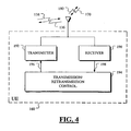
- Fig. 4 shows the UE of Fig. 1 or Fig. 3 at a level of detail sufficient to show the elements needed to carry out the present invention.
- the UE 160 includes a receiver 190 responsive to the downlink 170 from the Node B 110 and the downlink 138 from the Node B 132.
- the UE 160 also includes a transmitter 192 for providing the uplink 180 from the UE to the Node B 110 and the uplink 136 from the UE 162 the Node B 132.
- a retransmission control 194 provides a signal on a line 196 to the transmitter 192 and receives a signal 198 from the receiver 190. Referring both to Figs.
- an acknowledge/negative acknowledge signal may be received on one or both of the downlinks 138, 170 by the receiver 190 which in turn provides the received signal on the line 198 to the retransmission control 194.
- the retransmission control evaluates the acknowledgement or negative acknowledgement signal and decides whether a retransmission is required or not. If a retransmission is required, the retransmission control sees to it that the retransmission is provided on the signal line 196 to the transmitter 192 which in turn transmits a retransmission on one or both of the uplinks 136, 180.
- the retransmission control 194 can be viewed as a transmission control or a transmission/retransmission control. In other words, a packet is transmitted, retransmitted or both by the control 194.
- the present invention discloses various information elements and parameters in general terms without necessarily specifying exactly which existing or new message signal is to be used to communicate the information elements and parameters.
- IEs information elements
- One of the more important decisions yet to be made involves which network entity, node, or element will decide the values of parameters.
- a radio network controller has an E-DCH configuration signalling interface comprising the information elements and parameters described in further detail below and exchanged over the lub lines 133, 134 or over the lur lines 140, 150, or both.
- a Node B has an E-DCH configuration signalling interface comprising the information elements and parameters described in further detail below and exchanged over the lub lines 133, 134 or 120, 122.
- a system has one or more radio network controllers and at least one Node B each with an E-DCH configuration signalling interface as described above and comprising the information elements and parameters described in further detail below.
- Case(2) is a typical procedure for a Cell specific parameter. That means RNC configures the E-DCH resource pool and Node B decides the exact value according to the air interface situation.
- Case(3) is valid in case that Node B knows the resource situation, the air interface condition, other E-DCH parameter usage but SRNC has to manage the overall resource situation.
- parameters are provided on the lub interface, the lur interface, or both, that define either cell-specific parameters, RL-specific parameters, or both, for E-DCH.
- Such may include but are not limited to the following parameters: (1)Prx_nrt_Node B, (2)Prx_Target, (3)Node B TFCI Threshold, (4)UE TFCI Threshold, (5)ACK-NACK Power Offset, (6)ACK-NACK Repetition Factor, (7)Rate Grant Power Offset, (8)Rate Grant Repetition Factor, (9)UE Threshold Dtx, (10)UE Threshold Dtx Delay, (11)UE Capability Information, (12)HARQ Memory Partitioning, (13)Guideline Information for Node B Scheduling, (14) QoS, (15) delay due to UE Ptx Power and (16) TrCH under Node B control. The nature of each of these parameters is explained in more detail below.
- new semi-static IEs which configure E-DCH resources in a cell can be added in Cell Setup/Cell Reconfiguration procedure or Common Transport Channel Setup/Common Transport Channel Reconfiguration procedure or Physical Shared Channel Reconfiguration procedure or a new procedure.
- Radio Link (RL) related IEs to setup and re-configure E-DCH channels are listed below.
- the parameters conveyed on the line 133 from the SRNC to the Node B 132 can be added into a Radio Link Setup Request message, in a Radio Link Reconfiguration Prepare message, in a Radio Link Reconfiguration Request message or in some new message yet to be defined.
- the parameters conveyed on the line 134 from Node B 132 to SRNC 130 can be added into a Radio Link Setup Response message, a Radio Link Reconfiguration Ready message, a Radio Link Reconfiguration Response message or can be conveyed in a new message that has not yet been defined or standardized.
- Node B 132 if Node B 132 has to propose a value for a parameter, it can reuse the Radio Link Parameter Update Indication message or define a new message for delivery on the line 134 to the RNC 130.
- the SRNC 130 After the SRNC 130 receives the proposal from Node B 132 , it can reuse the Synchronised/Unsynchronised Radio Link Reconfiguration procedure or define a new procedure.
- the same parameters to setup and re-configure may be exchanged between the SRNC 130 and the other Node B 110 via the DRNC 100 using the Iur interface 140,150 between the SRNC 130 and the DRNC 100 and the tub interface 120,122 between the DRNC 100 and the other Node B 110.
- IEs which are defined in the DCH FDD Information IE group and DCH Information Response IE group, are same with the definitions in 3GPP specification.
- the additional IEs will be explained further below.
- the IE structure shows only one example. Thus it could be vary without contradicting the main concept of invention.
- IEs can be included in CELL SETUP REQUEST message or/and CELL RECONFIGURATION REQUEST message or Common Transport Channel Setup message or/and Common Transport Channel Reconfiguration Request message or Physical Shared Channel Reconfiguration Request message or a new message from CRNC to Node B.
- Prx_nrt_NodeB IE defines the total allowable interference due to E-DCH users. Node B scheduler has to take this into account when it grants bit rates to UEs. The scheduler may not let the sum of E-DCH users' noise rise exceed this value. In principle this is the part of load reserved for E-DCH users. IE/Group Name Presence Range IE type and reference Semantics description Prx_nrt_NodeB
- Prx_nrt_NodeB IE some other parameter than Prx_nrt_NodeB IE can be used like allowed bitrate. Which RRM algorithm will be used should be decided later.
- Prx_nrt_NodeB Node B needs to have knowledge to link between the data rate it will assign to UE and the consumption of Prx_nrt_NodeB as well. How Node B will obtain this information has to be decided later.
- the Prx Target IE defines the target of the total uplink load of the cell to help Node B scheduling. Thus Node B can optimize the capacity in a cell even if there are not so many E-DCH users in a cell.
- Parameters from SRNC to Node B can be included in a Radio Link Setup Request message, a Radio Link Reconfiguration Prepare message, or a Radio Link Reconfiguration Request message. Otherwise a new message can be defined for E-DCH parameter delivery. Parameters from Node B to SRNC can be added in a Radio Link Setup Response message, a Radio Link Reconfiguration Ready message, or a Radio Link Reconfiguration Response message. Otherwise a new message can be defined for this purpose.
- Parameters which have to have the same values in both the network and the UE have to have the same values can be included in the Radio Link Parameter Update Indication message or a new message to allow Node B to be able to indicated its willingness of changing the parameter to SRNC.
- E-DCH users are basically DCH user, basic parameters (i.e., not E-DCH specific) are already defined in the earlier release. (e.g., TFCI) Therefore in this section, only new E-DCH parameters are explained.
- the Node B TFCI Threshold IE sets the maximum data rate TFC the Node B scheduler is allowed to grant to the UE.
- the UE TFCI Threshold IE sets the maximum data rate TFC the UE is allowed to use. After receiving this value from the RNC, the Node B scheduler can adjust this parameter independently and signal it to the UE in the limits of Node B TFCI Threshold.
- the ACKNACK PO IE is assigned by SRNC as similar way than HSDPA. With this PO Node B can set the power of Hybrid ARQ ACK/NACK information transmission to the UE.
- ACK and NACK could be signalled with different power offsets thus having a dedicated IE for ACK power offset and NACK power offset. Further this or these could be cell specific parameters applicable to all the E-DCH users or radio link specific, i.e. defined separately for each UE.
- the ACKNACK Repetition Factor IE is assigned by SRNC as similar way than HSDPA. It defines, how many times the Hybrid ARQ ACK/NACK is repeated. Since ACK/NACK repetition Factor for HSDPA is defined in HSDPA IE group, it is not supposed to be reused. IE/Group Name Presence Range IE type and reference Semantics description ACKNACK Repetition Factor INTEGER
- the Rate Grant PO IE is assigned by SRNC as similar way than ACK/NACK PO. With this PO Node B can set the power of the scheduling related downlink signalling. This could be cell specific parameter applicable to all the E-DCH users or radio link specific, i.e. defined separately for each UE.
- IE/Group Name Presence Range IE type and reference Semantics description Rate Grant PO INTEGER
- Rate Grant Repetition Factor IE is assigned by SRNC. It defines, how many times the scheduling related downlink signalling is repeated. IE/Group Name Presence Range IE type and reference Semantics description Rate Grant Repetition Factor INTEGER
- the Rate Request PO IE is assigned by SRNC as similar way than ACK/NACK PO. With this PO Node B knows the power offset applied by the UE to the uplink related scheduling signalling. This parameter makes Node B receiver simpler when it acquires the uplink scheduling signalling information from UE.
- IE/Group Name Presence Range IE type and reference Semantics description Rate Request PO INTEGER
- Rate Request Repetition Factor IE is assigned by SRNC. Node B will use this value when it receives Rate Request Information from UE. It defines, how many times the scheduling related uplink signalling is repeated.
- the UE Threshold Dtx IE is assigned by SRNC. Node B scheduler will lower the UE TFCI Threshold to this value after the UE has been inactive for a period set by UE Threshold Dtx Delay IE/Group Name Presence Range IE type and reference Semantics description UE Threshold Dtx INTEGER
- the Delay due to UE Pfx Power IE defines the period in which UE is not using the maximum bit rate due to the UE Ptx Power limitation. If the UE has not been using the maximum allowed data rate for the duration of the delay but has not been completely inactive (i.e. has transmitted some data on E-DCH during the delay but has not been using the maximum allowed data rate), for the duration of this delay, the Node B assumes that the UE is not capable of transmitting with that high a data rate due to power limitation or the UE produces data to transmit in a lower rate than would be the maximum allowed, and can perform accordingly.
- a proposed functionality would be to drop the maximum allowed data rate to what is indicated by 'UE Threshold DTX' IE.
- the TrCH under Node B control IE indicates which transport channels are under Node B scheduling control. Thus Node B can use this information for scheduling.
- One Coded Composite Transport Channel (CCTrCH) may have a number of transport channels (TrCH) combined to it and it is possible that some of the TrCHs may be controllable to the Node B and some not.
- the UE Capabilities Information IE provides information related to UE capabilities for E-DCH or alternatively the UE capabilities may be categorized and the UE category parameter can be signalled to the Node B.
- Number of HARQ process could be one example in this IE group. And further UE Capability parameters will be defined.
- the HARQ Memory Partitioning IE provides information for HARQ memory usage.
- This parameter can be that Node B, depending on the scheduler processing speed etc, decides how many ARQ processes are needed. If the TTI is 10 ms then the number of ARQ processes should be less than with the 2 ms HSDPA TTI. (There were 8 processes with HSDPA, impact of the timing of downlink signaling to be taken into account as well).
- Node B informs UE (via SRNC) the number of processes to be used and the memory per ARQ process.
- UE would be assuming even memory partitioning for all ARQ processes to avoid UE having to determine separately every TTI how much data with what coding can be transmitted in a given TTI.
- QoS parameter like traffic class, SPI, GBR parameter, discard timer etc.
- each of the network elements including the RNCs 100, 130, the Node Bs 110, 132 and the UE 160 will typically include a signal processor that may be a special or general-purpose signal processor.
- a central processing unit (CPU) may be provided along with memory devices including both permanent memory and memory for storing information temporarily. Input/output ports are provided and all of these various devices are interconnected by data, address, and control signal lines.
- the permanent memory may be used to store instructions coded according to a selected computer programming language for carrying out the formation of the messages described above with information elements for conveying the above-described parameters. Therefore, it should be understood that these various components within a given network element or device constitute means for implementing the interfaces disclosed above.
Landscapes
- Engineering & Computer Science (AREA)
- Computer Networks & Wireless Communication (AREA)
- Signal Processing (AREA)
- Mobile Radio Communication Systems (AREA)
- Agricultural Chemicals And Associated Chemicals (AREA)
Applications Claiming Priority (2)
| Application Number | Priority Date | Filing Date | Title |
|---|---|---|---|
| US10/802,391 US8243633B2 (en) | 2004-03-16 | 2004-03-16 | Enhanced uplink dedicated channel—application protocol over lub/lur |
| PCT/IB2005/000589 WO2005089050A2 (en) | 2004-03-16 | 2005-03-08 | Enhanced uplink dedicated channel - application protocol over iub/iur |
Publications (2)
| Publication Number | Publication Date |
|---|---|
| EP1726131A2 EP1726131A2 (en) | 2006-11-29 |
| EP1726131B1 true EP1726131B1 (en) | 2013-04-24 |
Family
ID=34986175
Family Applications (1)
| Application Number | Title | Priority Date | Filing Date |
|---|---|---|---|
| EP05708692.8A Active EP1726131B1 (en) | 2004-03-16 | 2005-03-08 | Enhanced uplink dedicated channel - application protocol over iub/iur |
Country Status (11)
| Country | Link |
|---|---|
| US (1) | US8243633B2 (ja) |
| EP (1) | EP1726131B1 (ja) |
| JP (1) | JP2007529938A (ja) |
| KR (1) | KR100862046B1 (ja) |
| CN (2) | CN101384022B (ja) |
| AU (2) | AU2005222663B2 (ja) |
| BR (1) | BRPI0509247A (ja) |
| CA (1) | CA2557937C (ja) |
| RU (1) | RU2403678C2 (ja) |
| WO (1) | WO2005089050A2 (ja) |
| ZA (1) | ZA200607690B (ja) |
Families Citing this family (78)
| Publication number | Priority date | Publication date | Assignee | Title |
|---|---|---|---|---|
| BRPI0117120B1 (pt) * | 2001-08-21 | 2016-06-14 | 2011 Intellectual Property Asset Trust | método para prover o elemento de rede da rede de comunicação, rede de comunicação, controlador e elemento de rede para a rede de comunicação |
| US9661519B2 (en) | 2003-02-24 | 2017-05-23 | Qualcomm Incorporated | Efficient reporting of information in a wireless communication system |
| US7218948B2 (en) | 2003-02-24 | 2007-05-15 | Qualcomm Incorporated | Method of transmitting pilot tones in a multi-sector cell, including null pilot tones, for generating channel quality indicators |
| US8514692B2 (en) | 2003-02-24 | 2013-08-20 | Qualcomm Incorporated | Methods and apparatus for determining, communicating and using information which can be used for interference control purposes |
| US8811348B2 (en) | 2003-02-24 | 2014-08-19 | Qualcomm Incorporated | Methods and apparatus for generating, communicating, and/or using information relating to self-noise |
| US9544860B2 (en) | 2003-02-24 | 2017-01-10 | Qualcomm Incorporated | Pilot signals for use in multi-sector cells |
| US8488457B2 (en) | 2003-11-14 | 2013-07-16 | Interdigital Technology Corporation | Wireless communication method and apparatus for transferring buffered enhanced uplink data from a mobile station to a node-B |
| US8040834B2 (en) * | 2004-03-31 | 2011-10-18 | Interdigital Technology Corporation | Wireless communication method and apparatus for reporting traffic volume measurement information to support enhanced uplink data transmissions |
| KR101071816B1 (ko) * | 2004-04-02 | 2011-10-11 | 엘지전자 주식회사 | 무선 패킷 통신 시스템에서의 업링크 패킷 스케쥴링 방법 |
| WO2005112296A2 (en) * | 2004-04-29 | 2005-11-24 | Interdigital Technology Corporation | Wireless communication method and system for configuring radio access bearers for enhanced uplink services |
| CN101467355B (zh) * | 2004-04-30 | 2012-07-18 | 美商内数位科技公司 | 控制以增强上链传输失效统计为基础的下链发信信道传输功率的方法及系统 |
| US8259752B2 (en) | 2004-05-07 | 2012-09-04 | Interdigital Technology Corporation | Medium access control layer architecture for supporting enhanced uplink |
| US7643419B2 (en) * | 2004-05-07 | 2010-01-05 | Interdigital Technology Corporation | Method and apparatus for implementing a data lifespan timer for enhanced dedicated channel transmissions |
| WO2005115025A2 (en) * | 2004-05-07 | 2005-12-01 | Interdigital Technology Corporation | Wireless communication system and method for configuring cells with enhanced uplink services |
| GEP20125427B (en) | 2004-05-07 | 2012-03-26 | Interdigital Tech Corp | Method and apparatus for assigning hybrid-automatic repeat request processes |
| AU2005202512B8 (en) * | 2004-06-09 | 2008-06-05 | Samsung Electronics Co., Ltd. | Method and apparatus for data transmission in a mobile telecommunication system supporting enhanced uplink service |
| US7710911B2 (en) * | 2004-06-10 | 2010-05-04 | Interdigital Technology Corporation | Method and apparatus for dynamically allocating H-ARQ processes |
| CN102573031B (zh) * | 2004-06-17 | 2015-10-21 | 日本电气株式会社 | 上行链路分组数据发送功率控制方法 |
| US8897828B2 (en) | 2004-08-12 | 2014-11-25 | Intellectual Ventures Holding 81 Llc | Power control in a wireless communication system |
| CN101945442A (zh) * | 2004-09-17 | 2011-01-12 | 株式会社Ntt都科摩 | 移动通信方法以及基站 |
| US8503938B2 (en) | 2004-10-14 | 2013-08-06 | Qualcomm Incorporated | Methods and apparatus for determining, communicating and using information including loading factors which can be used for interference control purposes |
| US20060135189A1 (en) * | 2004-12-22 | 2006-06-22 | Shirish Nagaraj | Method of controlling a received signal strength target in a wireless communication system |
| CN100515114C (zh) * | 2005-02-07 | 2009-07-15 | 上海贝尔阿尔卡特股份有限公司 | 一种用于hsupa的业务接纳控制方法及其装置 |
| JP4445933B2 (ja) * | 2005-02-09 | 2010-04-07 | 株式会社エヌ・ティ・ティ・ドコモ | 上り無線リソース割当方法、無線基地局及び無線回線制御局 |
| US8942716B2 (en) * | 2005-02-24 | 2015-01-27 | Ntt Docomo, Inc. | Radio resource control method, radio base station, and radio network controller |
| GB2425684B (en) * | 2005-04-28 | 2008-04-02 | Siemens Ag | A method of controlling noise rise in a cell |
| GB2427097B (en) | 2005-05-03 | 2007-03-21 | Ipwireless Inc | Method and apparatus for transmitting uplink signalling information |
| US8804626B2 (en) * | 2005-05-10 | 2014-08-12 | Ntt Docomo, Inc. | Transmission rate control method, mobile station, radio network controller, and radio base station |
| FI20055370A0 (fi) * | 2005-06-30 | 2005-06-30 | Nokia Corp | Resurssien allokointimenetelmä, viestintäjärjestelmä, verkkoelementti, moduuli, tietokoneohjelmatuote ja tietokoneohjelman jakeluväline |
| US8694042B2 (en) | 2005-10-14 | 2014-04-08 | Qualcomm Incorporated | Method and apparatus for determining a base station's transmission power budget |
| US9191840B2 (en) | 2005-10-14 | 2015-11-17 | Qualcomm Incorporated | Methods and apparatus for determining, communicating and using information which can be used for interference control |
| CN100382629C (zh) * | 2005-11-30 | 2008-04-16 | 华为技术有限公司 | 通过Iub接口进行专用测量的方法 |
| US8437251B2 (en) | 2005-12-22 | 2013-05-07 | Qualcomm Incorporated | Methods and apparatus for communicating transmission backlog information |
| US9572179B2 (en) | 2005-12-22 | 2017-02-14 | Qualcomm Incorporated | Methods and apparatus for communicating transmission backlog information |
| US9119220B2 (en) | 2005-12-22 | 2015-08-25 | Qualcomm Incorporated | Methods and apparatus for communicating backlog related information |
| US20070249287A1 (en) | 2005-12-22 | 2007-10-25 | Arnab Das | Methods and apparatus for selecting between a plurality of dictionaries |
| US8514771B2 (en) | 2005-12-22 | 2013-08-20 | Qualcomm Incorporated | Methods and apparatus for communicating and/or using transmission power information |
| US9137072B2 (en) | 2005-12-22 | 2015-09-15 | Qualcomm Incorporated | Methods and apparatus for communicating control information |
| US9125093B2 (en) | 2005-12-22 | 2015-09-01 | Qualcomm Incorporated | Methods and apparatus related to custom control channel reporting formats |
| US9338767B2 (en) | 2005-12-22 | 2016-05-10 | Qualcomm Incorporated | Methods and apparatus of implementing and/or using a dedicated control channel |
| US9148795B2 (en) | 2005-12-22 | 2015-09-29 | Qualcomm Incorporated | Methods and apparatus for flexible reporting of control information |
| US9451491B2 (en) | 2005-12-22 | 2016-09-20 | Qualcomm Incorporated | Methods and apparatus relating to generating and transmitting initial and additional control information report sets in a wireless system |
| US9125092B2 (en) | 2005-12-22 | 2015-09-01 | Qualcomm Incorporated | Methods and apparatus for reporting and/or using control information |
| US20070149132A1 (en) | 2005-12-22 | 2007-06-28 | Junyl Li | Methods and apparatus related to selecting control channel reporting formats |
| US9473265B2 (en) | 2005-12-22 | 2016-10-18 | Qualcomm Incorporated | Methods and apparatus for communicating information utilizing a plurality of dictionaries |
| CN100388866C (zh) * | 2005-12-30 | 2008-05-14 | 华为技术有限公司 | 配置增强的专用传输信道e-dch的方法和系统 |
| US20070243882A1 (en) | 2006-04-12 | 2007-10-18 | Qualcomm Incorporated | Method and apparatus for locating a wireless local area network associated with a wireless wide area network |
| US8228811B2 (en) * | 2006-05-17 | 2012-07-24 | Telefonaktiebolaget Lm Ericsson (Publ) | Enhanced uplink retransmission securing |
| EP2123095B1 (en) * | 2006-12-01 | 2010-06-30 | Interdigital Technology Corporation | Method and apparatus for controlling discontinuous transmission and reception |
| US7940721B2 (en) * | 2006-12-22 | 2011-05-10 | Alcatel-Lucent Usa Inc. | Power overload control method useful with enhanced dedicated channel traffic |
| CN101188550B (zh) * | 2007-03-21 | 2010-12-08 | 中兴通讯股份有限公司 | 报告小区对上行高阶调制的支持能力的方法和装置 |
| CN101272612A (zh) * | 2007-03-23 | 2008-09-24 | 中兴通讯股份有限公司 | 漂移无线网络控制器报告传输时间间隔不支持能力的方法 |
| US8406255B2 (en) * | 2007-04-23 | 2013-03-26 | Qualcomm Incorporated | Method and apparatus for controlling data transmission in a wireless communication system |
| CN101188799B (zh) * | 2007-06-01 | 2010-12-01 | 中兴通讯股份有限公司 | 网络控制器报告小区最大不连续发送循环周期能力的方法 |
| ES2385749T3 (es) | 2007-08-22 | 2012-07-31 | Telefonaktiebolaget L M Ericsson (Publ) | Métodos y dispositivos para el control de la transmisión de datos |
| WO2009045909A2 (en) | 2007-09-28 | 2009-04-09 | Interdigital Patent Holdings, Inc. | Method and apparatus for terminating transmission of a message in an enhanced random access channel |
| MY150961A (en) | 2007-09-28 | 2014-03-31 | Interdigital Patent Holdings | Method and apparatus for high-speed transmission on rach |
| KR101568149B1 (ko) * | 2007-10-25 | 2015-11-11 | 시그널 트러스트 포 와이어리스 이노베이션 | Cell―fach 상태에서 강화된 mac―e/es 자원을 관리하고 설정하기 위한 방법 및 장치 |
| CN101426253B (zh) | 2007-10-31 | 2013-08-07 | 华为技术有限公司 | 一种实现信息传输的方法、装置及系统 |
| CN101426254B (zh) * | 2007-10-31 | 2010-12-08 | 华为技术有限公司 | 一种实现信息传输的方法、装置及系统 |
| US8917598B2 (en) | 2007-12-21 | 2014-12-23 | Qualcomm Incorporated | Downlink flow control |
| CN101911779A (zh) | 2008-01-02 | 2010-12-08 | 交互数字专利控股公司 | 用于小区重选的方法和设备 |
| US8699487B2 (en) | 2008-02-04 | 2014-04-15 | Qualcomm Incorporated | Uplink delay budget feedback |
| CN101940026B (zh) * | 2008-02-06 | 2014-05-07 | 爱立信电话股份有限公司 | 增强上行链路fach的网络控制吞吐量 |
| US7885212B2 (en) | 2008-02-06 | 2011-02-08 | Telefonaktiebolaget L M Ericsson (Publ) | Network controlled throughput for enhanced uplink FACH |
| US8656239B2 (en) | 2008-02-12 | 2014-02-18 | Qualcomm Incorporated | Control of data transmission based on HARQ in a wireless communication system |
| EP2485509B1 (en) * | 2009-10-01 | 2017-06-21 | Nec Corporation | Mobile communication system, base station apparatus, mobile station apparatus, control method, and computer readable medium |
| MX2013011811A (es) | 2011-04-13 | 2014-01-23 | Ericsson Telefon Ab L M | Metodo y dispositivo para la gestion del bufer del soft con base de las categorias de los equipos del usuario en una red de comunicaciones. |
| CN103002513A (zh) * | 2011-09-14 | 2013-03-27 | 中兴通讯股份有限公司 | 一种tsn长度配置方法及系统 |
| CN103167579B (zh) * | 2011-12-09 | 2015-12-16 | 华为技术有限公司 | 一种传输时间间隔的指示方法和装置 |
| WO2014000205A1 (zh) * | 2012-06-28 | 2014-01-03 | 华为技术有限公司 | 调整资源配置的方法、无线网络控制器和基站 |
| US9596714B2 (en) | 2012-08-13 | 2017-03-14 | Telefonaktiebolaget Lm Ericsson (Publ) | Methods and apparatuses for use in a mobile communication network |
| US20160262036A1 (en) * | 2014-05-09 | 2016-09-08 | Telefonaktiebolaget L M Ericsson (Publ) | Method and Arrangement for Forwarding UE Measurements |
| WO2016048227A2 (en) | 2014-09-25 | 2016-03-31 | Telefonaktiebolaget L M Ericsson (Publ) | Method and apparatus for enhanced uplink reference signal in listen-before-talk systems |
| CN107295678B (zh) * | 2016-04-01 | 2022-05-13 | 夏普株式会社 | 基站、用户设备和相关方法 |
| WO2019074433A1 (en) * | 2017-10-10 | 2019-04-18 | Telefonaktiebolaget Lm Ericsson (Publ) | BIT RATE MANAGEMENT FOR EU SUPPORTS |
| US11201702B2 (en) * | 2018-11-13 | 2021-12-14 | At&T Intellectual Property I, L.P. | Facilitating hybrid automatic repeat request reliability improvement for advanced networks |
| US11434754B2 (en) * | 2019-05-28 | 2022-09-06 | Erdos Miller, Inc. | Automated telemetry for switching transmission modes of a downhole device |
Family Cites Families (29)
| Publication number | Priority date | Publication date | Assignee | Title |
|---|---|---|---|---|
| WO1997028505A1 (en) * | 1996-01-31 | 1997-08-07 | Ipsilon Networks, Inc. | Improved method and apparatus for dynamically shifting between routing and switching packets in a transmission network |
| SE519210C2 (sv) * | 1997-06-06 | 2003-01-28 | Ericsson Telefon Ab L M | Förfarande för att minimera uppkopplingsfördröjningen för ett mobilriktat meddelande i cellulärt radiokommunikationssystem |
| US6400695B1 (en) | 1998-05-22 | 2002-06-04 | Lucent Technologies Inc. | Methods and apparatus for retransmission based access priority in a communications system |
| EP1041850A1 (en) | 1999-04-01 | 2000-10-04 | Nortel Matra Cellular | Method and apparatus for changing radio link configurations in a mobile telecommunications system with soft handover |
| AU2001240443A1 (en) | 2000-01-25 | 2001-08-07 | Siemens Aktiengesellschaft | Method for signaling a channel assignment in a radio communication system |
| US6539030B1 (en) * | 2000-02-07 | 2003-03-25 | Qualcomm Incorporated | Method and apparatus for providing configurable layers and protocols in a communications system |
| US6493331B1 (en) | 2000-03-30 | 2002-12-10 | Qualcomm Incorporated | Method and apparatus for controlling transmissions of a communications systems |
| US7016310B2 (en) * | 2000-04-05 | 2006-03-21 | Telefonaktiebolaget Lm Ericsson (Publ) | Deriving control parameters for telecommunications in-and-out-of-synchronization detection |
| US7181223B1 (en) * | 2000-06-21 | 2007-02-20 | Motorola, Inc. | Method for rapid uplink access by GSM GPRS/EDGE mobile stations engaged in voice over internet protocol packet transfer mode |
| JP4027071B2 (ja) * | 2000-10-18 | 2007-12-26 | エルジー エレクトロニクス インコーポレイティド | ハンドオーバ制御方法、移動局の同期転送タイミング変更方法、通信リンク制御方法および通信リンク制御システム |
| US7027828B2 (en) * | 2000-11-18 | 2006-04-11 | Lg Electronics Inc. | Method for controlling power of TFCI field for DSCH in 3G standard mobile communication system |
| US6889050B1 (en) * | 2000-11-22 | 2005-05-03 | Telefonaktiebolaget Lm Ericsson (Publ) | Variable transmission rate services in a radio access network |
| US7266107B2 (en) | 2000-11-23 | 2007-09-04 | Samsung Electronics Co., Ltd. | Apparatus and method for allocating a common channel in a CDMA mobile communication system |
| EP2490486A3 (en) * | 2000-12-26 | 2012-11-07 | Fujitsu Limited | Error rate control apparatus |
| US6625172B2 (en) * | 2001-04-26 | 2003-09-23 | Joseph P. Odenwalder | Rescheduling scheduled transmissions |
| US6845095B2 (en) * | 2001-04-27 | 2005-01-18 | Telefonaktiebolaget Lm Ericsson (Publ) | Efficient header handling involving GSM/EDGE radio access networks |
| US6996082B2 (en) * | 2001-05-14 | 2006-02-07 | Interdigital Technology Corporation | Method and apparatus for minimizing the amount of data necessary to signal code and timeslot assignments |
| US20020183053A1 (en) * | 2001-05-29 | 2002-12-05 | Muralimohan Gopalakrishna | Methods and systems for testing macrodiversity and handover functionality of a radio network controller |
| DE10130038A1 (de) | 2001-06-21 | 2003-01-02 | Voith Paper Patent Gmbh | Verfahren und Maschine zur Herstellung einer Faserstoffbahn |
| JP4192468B2 (ja) * | 2001-12-21 | 2008-12-10 | 日本電気株式会社 | 移動体通信システムおよび無線リンク再構築方法ならびにプログラム |
| KR100832117B1 (ko) * | 2002-02-17 | 2008-05-27 | 삼성전자주식회사 | 고속 순방향 패킷 접속 방식을 사용하는 이동통신 시스템에서 역방향 송신전력 오프셋 정보를 송수신하는 장치 및 방법 |
| CA2484725C (en) * | 2002-05-09 | 2011-09-13 | Nokia Corporation | Hsdpa cqi, ack, nack power offset known in node b and in srnc |
| US7539165B2 (en) | 2002-05-24 | 2009-05-26 | Antti Toskala | Method and apparatus for distributed signaling for uplink rate control |
| US6782269B2 (en) | 2002-06-17 | 2004-08-24 | Nokia Corporation | Two threshold uplink rate control to enable uplink scheduling |
| KR100606008B1 (ko) * | 2003-01-04 | 2006-07-26 | 삼성전자주식회사 | 부호 분할 다중 접속 통신 시스템에서 역방향 데이터재전송 요청 송수신 장치 및 방법 |
| KR100584431B1 (ko) * | 2003-02-14 | 2006-05-26 | 삼성전자주식회사 | 부호 분할 다중 접속 통신 시스템에서 역방향 데이터재전송 시스템 및 방법 |
| JP2004260620A (ja) * | 2003-02-26 | 2004-09-16 | Ntt Docomo Inc | 無線データ通信方法、サーバ装置及び無線制御装置 |
| KR20040083617A (ko) * | 2003-03-24 | 2004-10-06 | 삼성전자주식회사 | 향상된 역방향 전용전송채널을 서비스하는 비동기 방식의부호분할다중접속 이동통신시스템에서 소프트 핸드오버영역에 위치하는 이동단말이 역방향 데이터를 재전송하는방법 및 시스템 |
| US7239870B2 (en) * | 2003-11-05 | 2007-07-03 | Ipr Licensing, Inc. | Wireless communication method and apparatus with reconfigurable architecture for supporting an enhanced uplink soft handover operation |
-
2004
- 2004-03-16 US US10/802,391 patent/US8243633B2/en active Active
-
2005
- 2005-03-08 JP JP2007503428A patent/JP2007529938A/ja active Pending
- 2005-03-08 CN CN2008102124484A patent/CN101384022B/zh active Active
- 2005-03-08 CA CA2557937A patent/CA2557937C/en active Active
- 2005-03-08 RU RU2006132682/09A patent/RU2403678C2/ru active
- 2005-03-08 EP EP05708692.8A patent/EP1726131B1/en active Active
- 2005-03-08 KR KR1020067018933A patent/KR100862046B1/ko active IP Right Grant
- 2005-03-08 AU AU2005222663A patent/AU2005222663B2/en not_active Ceased
- 2005-03-08 BR BRPI0509247-7A patent/BRPI0509247A/pt not_active IP Right Cessation
- 2005-03-08 WO PCT/IB2005/000589 patent/WO2005089050A2/en active Application Filing
- 2005-03-08 CN CNA2005800083709A patent/CN1934887A/zh active Pending
-
2006
- 2006-09-14 ZA ZA200607690A patent/ZA200607690B/xx unknown
-
2008
- 2008-07-23 AU AU2008203286A patent/AU2008203286B2/en active Active
Also Published As
| Publication number | Publication date |
|---|---|
| CN1934887A (zh) | 2007-03-21 |
| CA2557937A1 (en) | 2005-09-29 |
| JP2007529938A (ja) | 2007-10-25 |
| AU2005222663A1 (en) | 2005-09-29 |
| KR100862046B1 (ko) | 2008-10-09 |
| CN101384022B (zh) | 2013-07-03 |
| EP1726131A2 (en) | 2006-11-29 |
| AU2008203286B2 (en) | 2009-03-05 |
| BRPI0509247A (pt) | 2007-09-04 |
| WO2005089050A2 (en) | 2005-09-29 |
| ZA200607690B (en) | 2008-05-28 |
| US20050207359A1 (en) | 2005-09-22 |
| AU2005222663B2 (en) | 2008-04-24 |
| RU2006132682A (ru) | 2008-04-27 |
| AU2008203286A1 (en) | 2008-08-28 |
| CA2557937C (en) | 2014-09-30 |
| CN101384022A (zh) | 2009-03-11 |
| US8243633B2 (en) | 2012-08-14 |
| WO2005089050A3 (en) | 2006-03-30 |
| KR20060122958A (ko) | 2006-11-30 |
| RU2403678C2 (ru) | 2010-11-10 |
Similar Documents
| Publication | Publication Date | Title |
|---|---|---|
| EP1726131B1 (en) | Enhanced uplink dedicated channel - application protocol over iub/iur | |
| EP1099355B1 (en) | Method and apparatus for the transmission of packets of data | |
| EP1810449B1 (en) | Method of transmitting/receiving control information of data channel for enhanced uplink data transmission | |
| EP1878155B1 (en) | Method of transmitting control information in wireless communication system and transmission window updating method using the same | |
| EP1983698B1 (en) | Improved transmission scheme of protocol data units during a procedure that comprises the reset of the protocol layer | |
| US9780927B2 (en) | Method and system for transferring wireless transmit/receive unit-specific information | |
| KR100630854B1 (ko) | 고속 다운링크 공유 채널 셀 변경을 용이하게 하는 사용자측 장비 | |
| US7869461B2 (en) | Scheduling mode dependent data transmissions | |
| EP1461889B1 (en) | Method and system of retransmission | |
| EP1838125B1 (en) | Efficient rise over thermal (RoT) control during soft handover | |
| EP1495554B1 (en) | Node b and rnc actions during a serving hsdpa cell change | |
| EP1358770B1 (en) | Method, system, radio network element and user equipment for dynamically switching a link layer protocol configuration | |
| US20100240375A1 (en) | Resource allocation | |
| MX2008002213A (es) | Metodo y aparato para reconfigurar el estrato mac en un sistema de comunicaciones movil. | |
| UA74413C2 (uk) | Канальна архітектура і спосіб передачі даних у зворотному каналі системи безпровідного зв'язку (варіанти) та спосіб контролю потужності передачі у зворотному допоміжному каналі і віддалений термінал у такій системі | |
| JP2008520125A5 (ja) | ||
| CN101084691B (zh) | 控制发送单元和接收单元组间无线信道传输的方法及设备 | |
| MXPA06010354A (en) | Enhanced uplink dedicated channel - application protocol over iub/iur | |
| JP2006521047A (ja) | 移動無線通信システムにおける電力制御の改善方法 | |
| EP2451205A1 (en) | Communication method, communication system and control apparatus |
Legal Events
| Date | Code | Title | Description |
|---|---|---|---|
| PUAI | Public reference made under article 153(3) epc to a published international application that has entered the european phase |
Free format text: ORIGINAL CODE: 0009012 |
|
| 17P | Request for examination filed |
Effective date: 20060823 |
|
| AK | Designated contracting states |
Kind code of ref document: A2 Designated state(s): AT BE BG CH CY CZ DE DK EE ES FI FR GB GR HU IE IS IT LI LT LU MC NL PL PT RO SE SI SK TR |
|
| DAX | Request for extension of the european patent (deleted) | ||
| 17Q | First examination report despatched |
Effective date: 20090529 |
|
| GRAP | Despatch of communication of intention to grant a patent |
Free format text: ORIGINAL CODE: EPIDOSNIGR1 |
|
| RIC1 | Information provided on ipc code assigned before grant |
Ipc: H04L 12/56 20060101AFI20121017BHEP Ipc: H04W 36/00 20090101ALI20121017BHEP |
|
| GRAS | Grant fee paid |
Free format text: ORIGINAL CODE: EPIDOSNIGR3 |
|
| REG | Reference to a national code |
Ref country code: DE Ref legal event code: R079 Ref document number: 602005039234 Country of ref document: DE Free format text: PREVIOUS MAIN CLASS: H04L0012560000 Ipc: H04L0012701000 |
|
| GRAA | (expected) grant |
Free format text: ORIGINAL CODE: 0009210 |
|
| AK | Designated contracting states |
Kind code of ref document: B1 Designated state(s): AT BE BG CH CY CZ DE DK EE ES FI FR GB GR HU IE IS IT LI LT LU MC NL PL PT RO SE SI SK TR |
|
| REG | Reference to a national code |
Ref country code: GB Ref legal event code: FG4D |
|
| RIC1 | Information provided on ipc code assigned before grant |
Ipc: H04L 12/701 20130101AFI20130320BHEP |
|
| REG | Reference to a national code |
Ref country code: DE Ref legal event code: R081 Ref document number: 602005039234 Country of ref document: DE Owner name: NOKIA TECHNOLOGIES OY, FI Free format text: FORMER OWNER: NOKIA CORP., 02610 ESPOO, FI |
|
| REG | Reference to a national code |
Ref country code: CH Ref legal event code: EP |
|
| REG | Reference to a national code |
Ref country code: AT Ref legal event code: REF Ref document number: 609176 Country of ref document: AT Kind code of ref document: T Effective date: 20130515 |
|
| REG | Reference to a national code |
Ref country code: IE Ref legal event code: FG4D |
|
| REG | Reference to a national code |
Ref country code: DE Ref legal event code: R096 Ref document number: 602005039234 Country of ref document: DE Effective date: 20130620 |
|
| REG | Reference to a national code |
Ref country code: NL Ref legal event code: T3 |
|
| REG | Reference to a national code |
Ref country code: AT Ref legal event code: MK05 Ref document number: 609176 Country of ref document: AT Kind code of ref document: T Effective date: 20130424 |
|
| REG | Reference to a national code |
Ref country code: LT Ref legal event code: MG4D |
|
| PG25 | Lapsed in a contracting state [announced via postgrant information from national office to epo] |
Ref country code: PT Free format text: LAPSE BECAUSE OF FAILURE TO SUBMIT A TRANSLATION OF THE DESCRIPTION OR TO PAY THE FEE WITHIN THE PRESCRIBED TIME-LIMIT Effective date: 20130826 Ref country code: ES Free format text: LAPSE BECAUSE OF FAILURE TO SUBMIT A TRANSLATION OF THE DESCRIPTION OR TO PAY THE FEE WITHIN THE PRESCRIBED TIME-LIMIT Effective date: 20130804 Ref country code: SE Free format text: LAPSE BECAUSE OF FAILURE TO SUBMIT A TRANSLATION OF THE DESCRIPTION OR TO PAY THE FEE WITHIN THE PRESCRIBED TIME-LIMIT Effective date: 20130424 Ref country code: GR Free format text: LAPSE BECAUSE OF FAILURE TO SUBMIT A TRANSLATION OF THE DESCRIPTION OR TO PAY THE FEE WITHIN THE PRESCRIBED TIME-LIMIT Effective date: 20130725 Ref country code: SI Free format text: LAPSE BECAUSE OF FAILURE TO SUBMIT A TRANSLATION OF THE DESCRIPTION OR TO PAY THE FEE WITHIN THE PRESCRIBED TIME-LIMIT Effective date: 20130424 Ref country code: AT Free format text: LAPSE BECAUSE OF FAILURE TO SUBMIT A TRANSLATION OF THE DESCRIPTION OR TO PAY THE FEE WITHIN THE PRESCRIBED TIME-LIMIT Effective date: 20130424 Ref country code: BE Free format text: LAPSE BECAUSE OF FAILURE TO SUBMIT A TRANSLATION OF THE DESCRIPTION OR TO PAY THE FEE WITHIN THE PRESCRIBED TIME-LIMIT Effective date: 20130424 Ref country code: IS Free format text: LAPSE BECAUSE OF FAILURE TO SUBMIT A TRANSLATION OF THE DESCRIPTION OR TO PAY THE FEE WITHIN THE PRESCRIBED TIME-LIMIT Effective date: 20130824 Ref country code: LT Free format text: LAPSE BECAUSE OF FAILURE TO SUBMIT A TRANSLATION OF THE DESCRIPTION OR TO PAY THE FEE WITHIN THE PRESCRIBED TIME-LIMIT Effective date: 20130424 Ref country code: FI Free format text: LAPSE BECAUSE OF FAILURE TO SUBMIT A TRANSLATION OF THE DESCRIPTION OR TO PAY THE FEE WITHIN THE PRESCRIBED TIME-LIMIT Effective date: 20130424 |
|
| PG25 | Lapsed in a contracting state [announced via postgrant information from national office to epo] |
Ref country code: CY Free format text: LAPSE BECAUSE OF FAILURE TO SUBMIT A TRANSLATION OF THE DESCRIPTION OR TO PAY THE FEE WITHIN THE PRESCRIBED TIME-LIMIT Effective date: 20130424 Ref country code: PL Free format text: LAPSE BECAUSE OF FAILURE TO SUBMIT A TRANSLATION OF THE DESCRIPTION OR TO PAY THE FEE WITHIN THE PRESCRIBED TIME-LIMIT Effective date: 20130424 Ref country code: BG Free format text: LAPSE BECAUSE OF FAILURE TO SUBMIT A TRANSLATION OF THE DESCRIPTION OR TO PAY THE FEE WITHIN THE PRESCRIBED TIME-LIMIT Effective date: 20130724 |
|
| PG25 | Lapsed in a contracting state [announced via postgrant information from national office to epo] |
Ref country code: DK Free format text: LAPSE BECAUSE OF FAILURE TO SUBMIT A TRANSLATION OF THE DESCRIPTION OR TO PAY THE FEE WITHIN THE PRESCRIBED TIME-LIMIT Effective date: 20130424 Ref country code: CZ Free format text: LAPSE BECAUSE OF FAILURE TO SUBMIT A TRANSLATION OF THE DESCRIPTION OR TO PAY THE FEE WITHIN THE PRESCRIBED TIME-LIMIT Effective date: 20130424 Ref country code: EE Free format text: LAPSE BECAUSE OF FAILURE TO SUBMIT A TRANSLATION OF THE DESCRIPTION OR TO PAY THE FEE WITHIN THE PRESCRIBED TIME-LIMIT Effective date: 20130424 Ref country code: SK Free format text: LAPSE BECAUSE OF FAILURE TO SUBMIT A TRANSLATION OF THE DESCRIPTION OR TO PAY THE FEE WITHIN THE PRESCRIBED TIME-LIMIT Effective date: 20130424 |
|
| PG25 | Lapsed in a contracting state [announced via postgrant information from national office to epo] |
Ref country code: IT Free format text: LAPSE BECAUSE OF FAILURE TO SUBMIT A TRANSLATION OF THE DESCRIPTION OR TO PAY THE FEE WITHIN THE PRESCRIBED TIME-LIMIT Effective date: 20130424 Ref country code: RO Free format text: LAPSE BECAUSE OF FAILURE TO SUBMIT A TRANSLATION OF THE DESCRIPTION OR TO PAY THE FEE WITHIN THE PRESCRIBED TIME-LIMIT Effective date: 20130424 |
|
| PLBE | No opposition filed within time limit |
Free format text: ORIGINAL CODE: 0009261 |
|
| STAA | Information on the status of an ep patent application or granted ep patent |
Free format text: STATUS: NO OPPOSITION FILED WITHIN TIME LIMIT |
|
| 26N | No opposition filed |
Effective date: 20140127 |
|
| REG | Reference to a national code |
Ref country code: DE Ref legal event code: R097 Ref document number: 602005039234 Country of ref document: DE Effective date: 20140127 |
|
| REG | Reference to a national code |
Ref country code: HU Ref legal event code: AG4A Ref document number: E018770 Country of ref document: HU |
|
| PG25 | Lapsed in a contracting state [announced via postgrant information from national office to epo] |
Ref country code: LU Free format text: LAPSE BECAUSE OF FAILURE TO SUBMIT A TRANSLATION OF THE DESCRIPTION OR TO PAY THE FEE WITHIN THE PRESCRIBED TIME-LIMIT Effective date: 20140308 |
|
| REG | Reference to a national code |
Ref country code: CH Ref legal event code: PL |
|
| GBPC | Gb: european patent ceased through non-payment of renewal fee |
Effective date: 20140308 |
|
| REG | Reference to a national code |
Ref country code: FR Ref legal event code: ST Effective date: 20141128 |
|
| REG | Reference to a national code |
Ref country code: IE Ref legal event code: MM4A |
|
| PG25 | Lapsed in a contracting state [announced via postgrant information from national office to epo] |
Ref country code: GB Free format text: LAPSE BECAUSE OF NON-PAYMENT OF DUE FEES Effective date: 20140308 Ref country code: LI Free format text: LAPSE BECAUSE OF NON-PAYMENT OF DUE FEES Effective date: 20140331 Ref country code: CH Free format text: LAPSE BECAUSE OF NON-PAYMENT OF DUE FEES Effective date: 20140331 Ref country code: IE Free format text: LAPSE BECAUSE OF NON-PAYMENT OF DUE FEES Effective date: 20140308 Ref country code: FR Free format text: LAPSE BECAUSE OF NON-PAYMENT OF DUE FEES Effective date: 20140331 |
|
| REG | Reference to a national code |
Ref country code: DE Ref legal event code: R081 Ref document number: 602005039234 Country of ref document: DE Owner name: NOKIA TECHNOLOGIES OY, FI Free format text: FORMER OWNER: NOKIA CORPORATION, ESPOO, FI Ref country code: DE Ref legal event code: R081 Ref document number: 602005039234 Country of ref document: DE Owner name: NOKIA TECHNOLOGIES OY, FI Free format text: FORMER OWNER: NOKIA CORPORATION, 02610 ESPOO, FI |
|
| REG | Reference to a national code |
Ref country code: NL Ref legal event code: PD Owner name: NOKIA TECHNOLOGIES OY; FI Free format text: DETAILS ASSIGNMENT: VERANDERING VAN EIGENAAR(S), OVERDRACHT; FORMER OWNER NAME: NOKIA CORPORATION Effective date: 20151111 |
|
| PG25 | Lapsed in a contracting state [announced via postgrant information from national office to epo] |
Ref country code: MC Free format text: LAPSE BECAUSE OF FAILURE TO SUBMIT A TRANSLATION OF THE DESCRIPTION OR TO PAY THE FEE WITHIN THE PRESCRIBED TIME-LIMIT Effective date: 20130424 |
|
| PG25 | Lapsed in a contracting state [announced via postgrant information from national office to epo] |
Ref country code: TR Free format text: LAPSE BECAUSE OF FAILURE TO SUBMIT A TRANSLATION OF THE DESCRIPTION OR TO PAY THE FEE WITHIN THE PRESCRIBED TIME-LIMIT Effective date: 20130424 |
|
| REG | Reference to a national code |
Ref country code: HU Ref legal event code: FH1C Free format text: FORMER REPRESENTATIVE(S): MAK ANDRAS, SBGK SZABADALMI UEGYVIVOEI IRODA, HU Representative=s name: DR. KOCSOMBA NELLI UEGYVEDI IRODA, HU Ref country code: HU Ref legal event code: GB9C Owner name: NOKIA TECHNOLOGIES OY, FI Free format text: FORMER OWNER(S): NOKIA CORPORATION, FI |
|
| REG | Reference to a national code |
Ref country code: HU Ref legal event code: HC9C Owner name: NOKIA TECHNOLOGIES OY, FI Free format text: FORMER OWNER(S): NOKIA CORPORATION, FI |
|
| REG | Reference to a national code |
Ref country code: DE Ref legal event code: R079 Ref document number: 602005039234 Country of ref document: DE Free format text: PREVIOUS MAIN CLASS: H04L0012701000 Ipc: H04L0045000000 |
|
| REG | Reference to a national code |
Ref country code: HU Ref legal event code: HC9C Owner name: NOKIA TECHNOLOGIES OY, FI Free format text: FORMER OWNER(S): NOKIA CORPORATION, FI |
|
| P01 | Opt-out of the competence of the unified patent court (upc) registered |
Effective date: 20230527 |
|
| PGFP | Annual fee paid to national office [announced via postgrant information from national office to epo] |
Ref country code: NL Payment date: 20240215 Year of fee payment: 20 |
|
| PGFP | Annual fee paid to national office [announced via postgrant information from national office to epo] |
Ref country code: HU Payment date: 20240220 Year of fee payment: 20 Ref country code: DE Payment date: 20240130 Year of fee payment: 20 |