EP1725030A2 - Method of providing time shift function in audio/video network and apparatus for the same - Google Patents
Method of providing time shift function in audio/video network and apparatus for the same Download PDFInfo
- Publication number
- EP1725030A2 EP1725030A2 EP06252525A EP06252525A EP1725030A2 EP 1725030 A2 EP1725030 A2 EP 1725030A2 EP 06252525 A EP06252525 A EP 06252525A EP 06252525 A EP06252525 A EP 06252525A EP 1725030 A2 EP1725030 A2 EP 1725030A2
- Authority
- EP
- European Patent Office
- Prior art keywords
- content
- broadcast
- module
- output apparatus
- storage apparatus
- Prior art date
- Legal status (The legal status is an assumption and is not a legal conclusion. Google has not performed a legal analysis and makes no representation as to the accuracy of the status listed.)
- Granted
Links
- 238000000034 method Methods 0.000 title claims abstract description 39
- 230000005540 biological transmission Effects 0.000 claims abstract description 22
- 230000006870 function Effects 0.000 description 62
- 238000010586 diagram Methods 0.000 description 10
- 238000005516 engineering process Methods 0.000 description 7
- 230000008569 process Effects 0.000 description 6
- 238000004891 communication Methods 0.000 description 5
- 230000003247 decreasing effect Effects 0.000 description 5
- 230000005236 sound signal Effects 0.000 description 4
- 238000007906 compression Methods 0.000 description 2
- 230000006835 compression Effects 0.000 description 2
- 230000006837 decompression Effects 0.000 description 2
- 238000007792 addition Methods 0.000 description 1
- 238000003491 array Methods 0.000 description 1
- 238000012937 correction Methods 0.000 description 1
- 238000013144 data compression Methods 0.000 description 1
- 230000003111 delayed effect Effects 0.000 description 1
- 230000001419 dependent effect Effects 0.000 description 1
- 230000000694 effects Effects 0.000 description 1
- 239000000284 extract Substances 0.000 description 1
- 238000007689 inspection Methods 0.000 description 1
- 230000002452 interceptive effect Effects 0.000 description 1
- 238000012986 modification Methods 0.000 description 1
- 230000004048 modification Effects 0.000 description 1
- 230000006855 networking Effects 0.000 description 1
- 230000010363 phase shift Effects 0.000 description 1
- 238000012545 processing Methods 0.000 description 1
- 230000004044 response Effects 0.000 description 1
- 239000000344 soap Substances 0.000 description 1
- 238000006467 substitution reaction Methods 0.000 description 1
- 238000012360 testing method Methods 0.000 description 1
Images


Classifications
-
- H—ELECTRICITY
- H04—ELECTRIC COMMUNICATION TECHNIQUE
- H04N—PICTORIAL COMMUNICATION, e.g. TELEVISION
- H04N5/00—Details of television systems
- H04N5/44—Receiver circuitry for the reception of television signals according to analogue transmission standards
- H04N5/50—Tuning indicators; Automatic tuning control
-
- H—ELECTRICITY
- H04—ELECTRIC COMMUNICATION TECHNIQUE
- H04N—PICTORIAL COMMUNICATION, e.g. TELEVISION
- H04N5/00—Details of television systems
- H04N5/76—Television signal recording
-
- H—ELECTRICITY
- H04—ELECTRIC COMMUNICATION TECHNIQUE
- H04N—PICTORIAL COMMUNICATION, e.g. TELEVISION
- H04N21/00—Selective content distribution, e.g. interactive television or video on demand [VOD]
- H04N21/40—Client devices specifically adapted for the reception of or interaction with content, e.g. set-top-box [STB]; Operations thereof
- H04N21/43—Processing of content or additional data, e.g. demultiplexing additional data from a digital video stream; Elementary client operations, e.g. monitoring of home network or synchronising decoder's clock; Client middleware
- H04N21/433—Content storage operation, e.g. storage operation in response to a pause request, caching operations
- H04N21/4333—Processing operations in response to a pause request
-
- H—ELECTRICITY
- H04—ELECTRIC COMMUNICATION TECHNIQUE
- H04N—PICTORIAL COMMUNICATION, e.g. TELEVISION
- H04N21/00—Selective content distribution, e.g. interactive television or video on demand [VOD]
- H04N21/40—Client devices specifically adapted for the reception of or interaction with content, e.g. set-top-box [STB]; Operations thereof
- H04N21/43—Processing of content or additional data, e.g. demultiplexing additional data from a digital video stream; Elementary client operations, e.g. monitoring of home network or synchronising decoder's clock; Client middleware
- H04N21/438—Interfacing the downstream path of the transmission network originating from a server, e.g. retrieving encoded video stream packets from an IP network
- H04N21/4383—Accessing a communication channel
-
- H—ELECTRICITY
- H04—ELECTRIC COMMUNICATION TECHNIQUE
- H04N—PICTORIAL COMMUNICATION, e.g. TELEVISION
- H04N5/00—Details of television systems
- H04N5/76—Television signal recording
- H04N5/765—Interface circuits between an apparatus for recording and another apparatus
Definitions
- Methods and apparatus consistent with the present invention relate to a time shift function and, more particularly, but not exclusively, to providing a time shift function for decreasing latency time caused by channel switching in an audio/video (A/V) network having a separate content storage apparatus.
- A/V audio/video
- the TV directs the digital-broadcast receiving apparatus to switch to a new channel, and the digital-broadcast receiving apparatus extracts broadcast content from the broadcast signals of the switched channel and transmits it to the content storage apparatus in response to the direction of the TV. Thereafter, the content storage apparatus stores the broadcast content transmitted from the digital-broadcasting receiving apparatus and again transmits the stored broadcast content to the TV.
- the content storage apparatus stores the broadcast content transmitted from the digital-broadcasting receiving apparatus and again transmits the stored broadcast content to the TV.
- a broadcast receiving apparatus comprising a restoration module arranged in use to restore broadcast content of received broadcast signals; a device interface module for transmitting the restored broadcast content to a content output apparatus and a content storage apparatus; and a control module arranged in use to interrupt the transmission of the broadcast content to the content output apparatus when a time shift function is requested.
- a content storage apparatus including a device interface module for receiving broadcast content from a broadcast receiving apparatus; a storage module for storing the received broadcast content; and a control module for transmitting the stored broadcast content to a content output apparatus through the device interface module when a time shift function is requested.
- the illustrated broadcast receiving apparatus 100 includes a broadcasting reception module 110, a conditional reception module 120, a restoration module 130, a smart card interface module 140, a network interface module 150, a control module 160 and a device interface module 170.
- the conditional reception module 120 performs a user authentication operation using the smart card 20. More particularly, the conditional reception module 120 compares an authentication parameter, which is included in the transport streams provided from the demodulator 114, with another authentication parameter, which is provided by the smart card interface module 140 through the reading of the smart card 20, and determines whether the user of the broadcast receiving apparatus 100 has the right to receive a broadcast. If the two authentication parameters are identical to each other, it can be determined that the user has the right to receive the broadcast. If not, it can be determined that the user does not have the right.
- control module 160 performs the tasks of establishing and disconnecting an A/V network connection with the content output apparatus 200 and the content storage apparatus 300 through the device interface module 170.
- the device interface module 170 communicates with the content output apparatus 200 and the content storage apparatus 300 via a wired or wireless medium.
- the device interface module 170 may use a security protocol, such as a high-bandwidth digital content protection (HDCP) or a digital transmission content protection (DTCP) protocol, in order to prevent the unauthorized copying of the broadcast content at the time of communicating with the content output apparatus 200 and the content storage apparatus 300.
- a security protocol such as a high-bandwidth digital content protection (HDCP) or a digital transmission content protection (DTCP) protocol
- the user request input module 240 may provide an input means, such as a keypad, a touch screen or the like. Furthermore, the user request input module 240 may provide a wireless interface module, which can receive control signals through a wireless medium, such as an infrared (IR) receiver or a Bluetooth module. As a result, the user can input desired control signals through a remote controller or a home server.
- a wireless medium such as an infrared (IR) receiver or a Bluetooth module.
- FIG. 4 is a block diagram illustrating the content storage apparatus 300 according to an exemplary embodiment of the present invention.
- the device interface module 310 receives broadcast content from the broadcast receiving apparatus 100 and transmits the broadcast content to the content output apparatus 200. Furthermore, the device interface module 310 transmits and receives commands to and from the broadcast receiving apparatus 100 and the content output apparatus 200.
- the content storage apparatus 300 may further include a separate interface module for transmitting and receiving commands to and from the broadcast receiving apparatus 100 and the content output apparatus 200.
- the device interface module 310 may provide a plurality of communication ports for connection with the broadcast receiving apparatus 100 and the content output apparatus 200.
- the decoding module 350 decodes the content stored in the storage module 330.
- the AN data decoding method used by the decoding module 350 corresponds to the AN data encoding method used by the encoding module 340.
- FIG. 5 is a flowchart illustrating the operation of the AN system according to an exemplary embodiment of the present invention.
- the flowchart illustrated in FIG. 5 illustrates a predetermined process when the A/V system is not activated with a time shift function.
- the encoding module 340 encodes the received broadcast content using a predetermined AN compression method at operation S445.
- the control module 160 of the broadcast receiving apparatus 100 determines whether a predetermined amount of time has elapsed from the reception time of a previous channel switching request at operation S520. If, it is determined that the new channel switching request has not been received after the predetermined time, the control module 160 transmits the broadcast content, which is restored by the restoration module 130, to the content storage module 300 via the device interface module 170. At this time, the predetermined time is set to the average time that has elapsed from the input of a previous channel switching request to the input of a new channel switching request when a user continuously switches channel using the channel switch buttons of a remote controller in order to browse channels. The predetermined time may be acquired, for example, through sample tests of many beta users.
Landscapes
- Engineering & Computer Science (AREA)
- Multimedia (AREA)
- Signal Processing (AREA)
- Two-Way Televisions, Distribution Of Moving Picture Or The Like (AREA)
- Signal Processing For Digital Recording And Reproducing (AREA)
- Television Signal Processing For Recording (AREA)
Abstract
Description
- Methods and apparatus consistent with the present invention relate to a time shift function and, more particularly, but not exclusively, to providing a time shift function for decreasing latency time caused by channel switching in an audio/video (A/V) network having a separate content storage apparatus.
- Recently, with the advancements in broadcasting technologies, implementation of digital broadcasting through satellite broadcasting, terrestrial broadcasting and cable broadcasting is gradually increasing. In order to receive digital broadcasts provided by a broadcast service provider, a digital-broadcast receiving apparatus such as a set-top box or a digital television (TV) capable of demodulating digital information is required at the user's side. In digital broadcasting, video and audio streams are compressed into packets of digital information prior to being transmitted. The digital-broadcast receiving apparatus then decompresses the digitized packets of video and audio information and outputs them to a display device.
- Recent set-top boxes and digital TVs which have been developed to receive digital broadcasts, also provide various functions unavailable in conventional analog TVs.
- For example, digital broadcasts commonly include an electronic program guide (EPG) which provides information about broadcast programs, in addition to video and audio information. Thus, viewers can readily obtain information about broadcast programs according to day, channel and time.
- Further, digital-broadcast receiving apparatuses may also have a time shift function which enables the apparatuses to extract a specific bit stream from the broadcast streams, store it in memory provided in the set-top box or the digital TV to be played at the request of a user. The time shift function allows viewers to record broadcast content while away and watch it later at their convenience.
- Recently, rather than having an embedded memory in the digital-broadcast receiving apparatus, an A/V system having a content storage apparatus separated from the digital-broadcast receiving apparatus has been developed. In this case, broadcast content is stored in the content storage apparatus rather than in the digital-broadcast receiving apparatus. The stored broadcast content is then transmitted from the content storage apparatus to a display device (e.g., TV) to be viewed by a user.
- Here, when the user switches channels, the TV directs the digital-broadcast receiving apparatus to switch to a new channel, and the digital-broadcast receiving apparatus extracts broadcast content from the broadcast signals of the switched channel and transmits it to the content storage apparatus in response to the direction of the TV. Thereafter, the content storage apparatus stores the broadcast content transmitted from the digital-broadcasting receiving apparatus and again transmits the stored broadcast content to the TV. As a result, in an A/V network environment in which a separate content storage apparatus is used to provide a time shift function, there is an inconvenience in that a viewer must wait for channel switching for a predetermined time after the viewer has switched channel using a remote controller. Therefore, decreasing the latency time caused by channel switching, when a separate content storage apparatus is used to provide a time shift function in an A/V network, is desired.
-
Korean Unexamined Patent Publication No. 2002-78339 Korean Unexamined Patent Publication No. 2002-78339 - Illustrative, non-limiting embodiments of the present invention aim to overcome the above disadvantages and other disadvantages not described above. According to an aspect of the present invention, there is provided a method of providing a time shift function, comprising: restoring broadcast content of received broadcast signals; transmitting the restored broadcast content to a content output apparatus; transmitting the restored broadcast content to a content storage apparatus; and interrupting the transmission of the broadcast content to the content output apparatus when the time shift function is requested.
- According to an aspect of the present invention, there is provided a method of providing a time shift function, comprising receiving broadcast content from a broadcast receiving apparatus; storing the received broadcast content; and transmitting the stored broadcast content to a content output apparatus when the time shift function is requested.
- According to an aspect of the present invention, there is provided a broadcast receiving apparatus comprising a restoration module arranged in use to restore broadcast content of received broadcast signals; a device interface module for transmitting the restored broadcast content to a content output apparatus and a content storage apparatus; and a control module arranged in use to interrupt the transmission of the broadcast content to the content output apparatus when a time shift function is requested.
- According to an aspect of the present invention, there is provided a content output apparatus including a control module arranged in use to determine one of a broadcast receiving apparatus and a content storage apparatus that will receive broadcast content, depending on whether a time shift function is requested; a device interface module for receiving the broadcast content from the broadcast receiving apparatus or the content storage apparatus based on the determination of the control module; and a content output module arranged in use to output the received broadcast content to a display device.
- According to an aspect of the present invention, there is provided a content storage apparatus including a device interface module for receiving broadcast content from a broadcast receiving apparatus; a storage module for storing the received broadcast content; and a control module for transmitting the stored broadcast content to a content output apparatus through the device interface module when a time shift function is requested.
- According to the present invention there is provided an apparatus and method as set forth in the appended claims. Preferred features of the invention will be apparent from the dependent claims, and the description which follows.
- In this way, latency time caused by channel switching, which is generated when a separate content storage apparatus is used to provide a time shift function may be decreased.
- For a better understanding of the invention, and to show how embodiments of the same may be carried into effect, reference will now be made, by way of example, to the accompanying diagrammatic drawings in which:
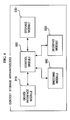
- FIG. 1 is a diagram illustrating an A/V system in which exemplary embodiments of the present invention can be used;
- FIG. 2 is a diagram illustrating a broadcast receiving apparatus according to an exemplary embodiment of the present invention;
- FIG. 3 is a block diagram illustrating a content output apparatus according to an exemplary embodiment of the present invention;
- FIG. 4 is a block diagram illustrating a content storage apparatus according to an exemplary embodiment of the present invention;
- FIG. 5 is a flowchart illustrating the operation of the A/V system according to an exemplary embodiment of the present invention;
- FIG. 6 is a flowchart illustrating a process in which a broadcast receiving apparatus transmits broadcast content to a content storage apparatus;
- FIG. 7 is a diagram illustrating a method of providing a time shift function according to an exemplary embodiment of the present invention; and
- FIG. 8 is a flowchart illustrating the operation of a content storage apparatus according to an exemplary embodiment of the present invention when a time shift function has been cancelled.
- Reference now will be made to the drawings, in which the same reference numerals are used throughout the different drawings to designate the same or similar components.
- FIG. 1 is a diagram illustrating an A/V system The AN system illustrated in FIG. 1 includes a
broadcast receiving apparatus 100, acontent output apparatus 200 and acontent storage apparatus 300. - The
broadcast receiving apparatus 100 receivesbroadcast signals 10 transmitted from a broadcast service provider, and restores broadcast content of the received broadcast signals. The broadcast content includes a variety of broadcast programs such as movies, soap operas, or news. - The
broadcast receiving apparatus 100 transmits the restored broadcast content to thecontent output apparatus 200 and thecontent storage apparatus 300. In this case, the transmission of the broadcast content to thecontent storage apparatus 300 can be performed when a user does not switch channel after a predetermined time. Further, when the user activates a time shift function, thebroadcast receiving apparatus 100 can interrupt the transmission of the broadcast content to thecontent output apparatus 200. Thebroadcast receiving apparatus 100 may be implemented using a set-top box or a network interface unit (NIT). - In the descriptions of the present invention, the time shift function refers to a function in which the
broadcast receiving apparatus 100 stores the broadcast content included in the received broadcast signals in thecontent storage apparatus 300, and thecontent output apparatus 200 provides the broadcast content stored in thecontent storage apparatus 300 to a display device (not shown) when requested by a user. Therefore, the broadcast content, which is provided to the display device according to the time shift function, is delayed in time with respect to the broadcast content included in the broadcast signals currently received by thebroadcast receiving apparatus 100. The time shift function includes detailed functions, such as a pause function, a reverse-play function and a fastforward function for current broadcast content, and a play function for previously viewed broadcast content. - The
content output apparatus 200 outputs the broadcast content, transmitted from thebroadcast receiving apparatus 100 or thecontent storage apparatus 300. For this, thecontent output apparatus 200 may include a speaker module (not shown) for outputting audio signals and a display module (not shown) for outputting video signals. Thecontent output apparatus 200 may be implemented using a digital TV, a projector, or a monitor. - The
content storage apparatus 300 refers to a kind of A/V hard disk drive (HDD) and stores broadcast content transmitted from thebroadcast receiving apparatus 100. When the user requests the time shift function, thecontent storage apparatus 300 transmits the stored broadcast content to thecontent output apparatus 200. - According to an exemplary embodiment of the present invention, the
broadcast receiving apparatus 100 and thecontent storage apparatus 300 may be connected to thecontent output apparatus 200 in a daisy chain fashion around thecontent output apparatus 200. As a result, when the user requests channel switching or the time shift function, thecontent output apparatus 200 can direct thebroadcast receiving apparatus 100 and thecontent storage apparatus 300 to perform tasks required for the channel switching or the time shift function. - Meanwhile, at the time of the transmission of data between the
broadcast receiving apparatus 100, thecontent output apparatus 200 and thecontent storage apparatus 300, a predetermined protocol, such as a high-bandwidth digital content protection (HDCP) protocol or a digital transmission content protection (DTCP) protocol, may be used. - According to an exemplary embodiment of the present invention, the A/V network illustrated in FIG. 1 may be implemented using expandable home theater (XHT) technology that acts as middleware for A/V home networking.
- The XHT technology is a home network solution using a digital TV, developed by Samsung Electronics Co., Ltd., that was adopted as a standard by the Consumer Electronics Association (CEA).
- The XHT technology allows users to control not only AN devices connected to the digital TV but also several digital TVs using a communication standard, that is, an Internet protocol, which is mainly used in IEEE 1394 cables for stably transmitting high definition (HD) class signals and the Internet. When using the XHT technology, the user in one room can view digital broadcast utilizing the digital broadcast reception function of a digital TV located in another room.
- The
broadcast receiving apparatus 100, thecontent output apparatus 200 and thecontent storage apparatus 300, which constitute the above-described AN system, are described below in detail. - FIG. 2 is a diagram illustrating a broadcast receiving apparatus according to an exemplary embodiment of the present invention.
- The illustrated
broadcast receiving apparatus 100 includes abroadcasting reception module 110, aconditional reception module 120, arestoration module 130, a smartcard interface module 140, anetwork interface module 150, acontrol module 160 and adevice interface module 170. - The
broadcasting reception module 110 functions to receive broadcast signals, and includes atuner 112 and ademodulator 114. - The
tuner 112 receives the broadcast signals of a channel selected by a user using a channel tuning operation, converts the received broadcast signals into intermediate frequencies, and outputs them to thedemodulator 114. For example, when thebroadcast receiving apparatus 100 illustrated in FIG. 2 receives a satellite broadcast, thetuner 112 detects I and Q signals by processing the signals received from a satellite, and outputs the detected I and Q signals to thedemodulator 114. - The
demodulator 114 restores transport streams from the signals, which have been converted into the intermediate frequencies, and outputs the restored transport streams to theconditional reception module 120. For example, thedemodulator 114 may be composed of a quadratic phase shift keying QPSK demodulator (not shown) and a forward error correction (FEC) demodulator (not shown), and can perform QPSK demodulation or FEC operations. - The
conditional reception module 120 performs a user authentication operation using thesmart card 20. More particularly, theconditional reception module 120 compares an authentication parameter, which is included in the transport streams provided from thedemodulator 114, with another authentication parameter, which is provided by the smartcard interface module 140 through the reading of thesmart card 20, and determines whether the user of thebroadcast receiving apparatus 100 has the right to receive a broadcast. If the two authentication parameters are identical to each other, it can be determined that the user has the right to receive the broadcast. If not, it can be determined that the user does not have the right. - If, as a result of the user authentication, it is determined that the user have the right to receive the broadcast, the
conditional reception module 120 descrambles the transport streams. However, if, as a result of the user authentication, it is determined that the user does not have the right theconditional reception module 120 does not descramble the transport streams. As a result, the descrambling operation is performed on the broadcast signals of a channel for which the user has paid for subscription, whereas the descrambling operation is not performed on the broadcast signals of a channel for which the user has not paid. - The
restoration module 130 restores the broadcast content using the transport streams descrambled by theconditional reception module 120. However, when theconditional reception module 120 does not descramble the transport streams, therestoration module 130 cannot normally restore the broadcast content included in the transport streams. - In order to restore the broadcast content, the
restoration module 130 includes ademultiplexing module 132 and adecoding module 134. - The
demultiplexing module 132 separates audio signals and video signals by parsing the transport streams descrambled by theconditional reception module 120, and outputs them to thedecoding module 134. - The
decoding module 134 includes a video decoder (not shown) and an audio decoder (not shown). The video and audio decoders respectively decode the video signals and audio signals provided from thedemultiplexing module 132. The video decoder can be implemented using a video decompression method such as Moving Picture Experts Group (MPEG)-2 or MPEG-4. The audio decoder can be implemented using an audio decompression method such as MPEG Layer-3 Audio (MP3) or Audio Compression 3 (AC3). - The smart
card interface module 140 reads a user'ssmart card 20 and outputs an authentication parameter stored in thesmart card 20 to theconditional reception module 120. According to another exemplary embodiment of the present invention, another type of portable storage medium that can store an authentication parameter, such as an SD card or a memory stick, may be used in place of thesmart card 20. In this case, the smartcard interface module 140 may be replaced with an interface module that can be connected to a corresponding portable storage medium. - The
network interface module 150 supports Internet Protocol-based communication, and connects to thebroadcast provider 100. Thebroadcast receiving apparatus 100 can provide services interactive with thebroadcast provider 100 to the user through thenetwork interface module 150. - The
control module 160 controls the operations of the modules, which constitute thebroadcast receiving apparatus 100. - When channel switching is activated by the
content output apparatus 200, thecontrol module 160 controls the broadcastsignal reception module 110 so as to receive the broadcast signals of a requested channel. Furthermore, when the time shift function is activated by thecontent output apparatus 200, thecontrol module 160 interrupts the transmission of the broadcast content to thecontent output apparatus 200. At this time, thecontrol module 160 can request the broadcast content to be provided thecontent output apparatus 200 from thecontent storage apparatus 300 through thedevice interface module 170. For the request, thecontrol module 160 can generate a predetermined command. - Meanwhile, the
control module 160 performs the tasks of establishing and disconnecting an A/V network connection with thecontent output apparatus 200 and thecontent storage apparatus 300 through thedevice interface module 170. Thedevice interface module 170 communicates with thecontent output apparatus 200 and thecontent storage apparatus 300 via a wired or wireless medium. - More particularly, the
device interface module 170 transmits the broadcast content to thecontent output apparatus 200 and thecontent storage apparatus 300. Furthermore, thedevice interface module 170 transmits and receives commands to and from thecontent output apparatus 200 and thecontent storage apparatus 300. However, this is merely exemplary, and thebroadcast receiving apparatus 100 according another exemplary embodiment of the present invention further includes a separate interface module for transmitting and receiving commands to and from thecontent output apparatus 200 and thecontent storage apparatus 300. - The
device interface module 170 may use a security protocol, such as a high-bandwidth digital content protection (HDCP) or a digital transmission content protection (DTCP) protocol, in order to prevent the unauthorized copying of the broadcast content at the time of communicating with thecontent output apparatus 200 and thecontent storage apparatus 300. - Meanwhile, the
device interface module 170 may provide a plurality of communication ports for connection with thecontent output apparatus 200 and thecontent storage apparatus 300. - FIG. 3 is a block diagram illustrating the
content output apparatus 200 according to an exemplary embodiment of the present invention. - The
content output apparatus 200 illustrated in FIG. 3 includes adevice interface module 210, acontrol module 220, acontent output module 230 and a userrequest input module 240. - The
device interface module 210 communicates with thebroadcast receiving apparatus 100 and thecontent storage apparatus 300 via a wired or wireless medium. - More particularly, the
device interface module 210 receives broadcast content from thebroadcast receiving apparatus 100 and thecontent storage apparatus 300. Furthermore, thedevice interface module 210 transmits and receives commands to and from thebroadcast receiving apparatus 100 and thecontent storage apparatus 300. However, this is merely exemplary, and thedevice interface module 210 according another exemplary embodiment of the present invention further includes a separate interface module for transmitting and receiving commands to and from thebroadcast receiving apparatus 100 and thecontent storage apparatus 300. - The
device interface module 210 may use a security protocol, such as an HDCP or DTCP protocol, in order to prevent the unauthorized copying of the broadcast content at the time of communicating with thebroadcast receiving apparatus 100 and thecontent storage apparatus 300. - Meanwhile, the
device interface module 210 may provide a plurality of communication ports for connection with thebroadcast receiving apparatus 100 and thecontent storage apparatus 300. - The
control module 220 controls the operations of functional blocks, which constitute thecontent output apparatus 200. - When channel switching is activated by the user
request input module 240, thecontrol module 220 performs channel switching from thebroadcast receiving apparatus 100 through thedevice interface module 210. Furthermore, when the time shift function is activated by thedevice interface module 210, thecontrol module 230 performs the time shift function from thebroadcast receiving apparatus 100 through thedevice interface module 210. Here, thecontrol module 220 may generate a predetermined command. - Meanwhile, the
control module 220 performs the tasks of establishing and disconnecting an AN network connection with thebroadcast receiving apparatus 100 and thecontent storage apparatus 300. - The
content output module 230 outputs the broadcast content received by thedevice interface module 210 to the user. For this, thecontent output module 230 may include a speaker module (not shown) and a display module (not shown). The speaker module outputs audio signals which constitute the broadcast audio content, and the display module outputs video signals which constitute the broadcast video content. - The user
request input module 240 receives control commands from the user. For example, the userrequest input module 240 may receive a channel switching request, a time shift request or the like from the user. - For this, the user
request input module 240 may provide an input means, such as a keypad, a touch screen or the like. Furthermore, the userrequest input module 240 may provide a wireless interface module, which can receive control signals through a wireless medium, such as an infrared (IR) receiver or a Bluetooth module. As a result, the user can input desired control signals through a remote controller or a home server. - FIG. 4 is a block diagram illustrating the
content storage apparatus 300 according to an exemplary embodiment of the present invention. - The
content storage apparatus 300 illustrated in FIG. 4 includes adevice interface module 310, acontrol module 320, astorage module 330, anencoding module 340 and a decoding module. - The
device interface module 310 communicates with thebroadcast receiving apparatus 100 and thecontent output apparatus 200 via a wired or wireless medium. - More particularly, the
device interface module 310 receives broadcast content from thebroadcast receiving apparatus 100 and transmits the broadcast content to thecontent output apparatus 200. Furthermore, thedevice interface module 310 transmits and receives commands to and from thebroadcast receiving apparatus 100 and thecontent output apparatus 200. However, this is merely exemplary, and thecontent storage apparatus 300 according another exemplary embodiment of the present invention may further include a separate interface module for transmitting and receiving commands to and from thebroadcast receiving apparatus 100 and thecontent output apparatus 200. - The
device interface 310 may use a security protocol, such as an HDCP or DTCP protocol, in order to prevent the unauthorized copying of the broadcast content at the time of communicating with thebroadcast receiving apparatus 100 and thecontent output apparatus 200. - Meanwhile, the
device interface module 310 may provide a plurality of communication ports for connection with thebroadcast receiving apparatus 100 and thecontent output apparatus 200. - The
control module 320 controls the operations of functional blocks, which constitute thecontent storage apparatus 300. - When the time shift function is activated by the
broadcast receiving apparatus 100 or thecontent output apparatus 200, thecontrol module 320 controls thedecoding module 350 so as to decode the broadcast content stored in thestorage module 330. Thereafter, thecontrol module 320 transmits the broadcast content decoded by thedecoding module 350 to thecontent output apparatus 200 via thedevice interface module 310. - Furthermore, when receiving the channel switching request from the
broadcast receiving apparatus 100 or thecontent output apparatus 200, thecontrol module 230 interrupts the transmission of the broadcast content to thecontent output apparatus 200. - Meanwhile, the
control module 320 performs the tasks of establishing and disconnecting an AN network connection with thebroadcast receiving apparatus 100 or thecontent output apparatus 200 through thedevice interface module 310. - The
storage module 330 stores the broadcast content transmitted from thebroadcast receiving apparatus 100. The broadcast content stored in thestorage module 330 is encoded by theencoding module 340 using an A/V data compression method, such as MPEG-2, MPEG-4, MP3 or AC3. - The
decoding module 350 decodes the content stored in thestorage module 330. The AN data decoding method used by thedecoding module 350 corresponds to the AN data encoding method used by theencoding module 340. - In the exemplary embodiments of FIGS. 2 to 4, the term 'module' refers to a software component or a hardware component, such as a field programmable gate-array (FPGA) or an application-specific integrated circuit (ASIC), and performs a specific function. However, the module is not limited to a software or hardware. The module may be configured to exist in an addressable storage medium or to perform one or more processes. Therefore, for example, the module includes components, such as software components, object-oriented software components, class components, or task components, processes, functions, attributes, procedures, subroutines, the segments of program code, drivers, firmware, micro-code, a circuit, data, a database, data structures, tables, arrays, and variables. Functions provided by the components and the modules are integrated into a smaller number of components and modules, or are separated into additional components and modules.
- The operation of the
broadcast receiving apparatus 100, thecontent output apparatus 200 and thecontent storage apparatus 300 are described below in detail. - FIG. 5 is a flowchart illustrating the operation of the AN system according to an exemplary embodiment of the present invention. The flowchart illustrated in FIG. 5 illustrates a predetermined process when the A/V system is not activated with a time shift function.
- When a channel switching request is received through the user
request input module 240 of thecontent output apparatus 200 at operation S410, thecontrol module 220 performs channel switching from thebroadcast receiving apparatus 100 via thedevice interface module 210 at operation S415. At this time, thecontrol module 220 generates a command for the channel switching and transmits it to thebroadcast receiving apparatus 100 via thedevice interface module 210. - When the
device interface module 170 of thebroadcast receiving apparatus 100 receives the command for the channel switching from thecontent output apparatus 200, the broadcastsignal reception module 110 performs a channel tuning operation to receive the broadcast signals of a requested channel at operation S420. Thereafter, therestoration module 130 restores broadcast content included in the broadcast signals received by the broadcastsignal reception module 110 at operation 425. Then, thedevice interface module 170 of thebroadcast receiving apparatus 100 transmits the restored broadcast content to thecontent output apparatus 200 at operation S430. Prior to transmitting the broadcast content, thecontrol module 160 of thebroadcast receiving apparatus 100 and thecontrol module 220 of thecontent output apparatus 200 can perform the task of establishing an A/V network connection respectively through thedevice interface module 170 of thebroadcast receiving apparatus 100 and thedevice interface module 210 of thecontent output apparatus 200. - When the
device interface module 210 of thecontent output apparatus 200 receives the broadcast content from thebroadcast receiving apparatus 100, thecontent output module 230 outputs it to a display device at operation S435. - Meanwhile, the
control module 160 of thebroadcast receiving apparatus 100 transmits the broadcast content restored by therestoration module 130 to thecontent storage apparatus 300 via thedevice interface module 170. Before the transmission of the broadcast content, thecontrol module 160 of thebroadcast receiving apparatus 100 and thecontrol module 320 of thecontent storage apparatus 300 may perform the task of establishing an A/V network connection respectively through thedevice interface module 170 of thebroadcast receiving apparatus 100 and thedevice interface module 310 of thecontent storage apparatus 300. - When the
device interface module 310 of thecontent storage apparatus 300 receives the broadcast content from thebroadcast receiving apparatus 100, theencoding module 340 encodes the received broadcast content using a predetermined AN compression method at operation S445. - Thereafter, the
storage module 330 stores the broadcast content encoded by theencoding module 340 at operation S450. - Meanwhile, operation S440, at which the
broadcast receiving apparatus 100 transmits the broadcast content to thecontent storage apparatus 300, can be performed depending on a predetermined condition, which is described below with reference to FIG. 6. - When receiving the channel switching request from the
content output apparatus 200 at operation S415, thecontrol unit 160 of thebroadcast receiving apparatus 100 determines whether a new channel switching request has been received from thecontent output apparatus 200 at operation S510. If it is determined that thedevice interface module 170 of thebroadcast receiving apparatus 100 has received the new channel switching request from thecontent output apparatus 200, thecontrol module 160 controls the functional blocks such that thebroadcast receiving apparatus 100 performs operations S420 to S430 of FIG. 5. - However, if it is determined in operation S510 that the new channel switching request has not been received, the
control module 160 of thebroadcast receiving apparatus 100 determines whether a predetermined amount of time has elapsed from the reception time of a previous channel switching request at operation S520. If, it is determined that the new channel switching request has not been received after the predetermined time, thecontrol module 160 transmits the broadcast content, which is restored by therestoration module 130, to thecontent storage module 300 via thedevice interface module 170. At this time, the predetermined time is set to the average time that has elapsed from the input of a previous channel switching request to the input of a new channel switching request when a user continuously switches channel using the channel switch buttons of a remote controller in order to browse channels. The predetermined time may be acquired, for example, through sample tests of many beta users. - As a result, the
content storage apparatus 300 cannot store broadcast content while the user browses channels, but stores the broadcast content when it is determined that the user has actually selected a specific channel and is viewing the broadcast content of the channel. - An exemplary embodiment in which a user activates the time shift function while the
content storage apparatus 300 stores the broadcast content is described below with reference to FIG. 7. - FIG. 7 is a diagram illustrating a method of providing a time shift function according to an exemplary embodiment of the present invention.
- When the time shift function is requested through the user
request input module 220 of thecontent output apparatus 200 at operation S610, thecontrol module 220 activate the time shift function from thebroadcast receiving apparatus 100 via thedevice interface module 210 at operation S620. At this time, thecontrol module 220 can generate a command for performing the time shift function and transmit it to thebroadcast receiving apparatus 100 via thedevice interface module 210. - When the
device interface module 170 of thebroadcast receiving apparatus 100 receives the command for the time shift function, thecontrol module 160 of thebroadcast receiving apparatus 100 interrupts the transmission of the broadcast content to thecontent output apparatus 200 at operation S630. At this time, thecontrol module 160 of thebroadcast receiving apparatus 100 and thecontrol module 220 of thecontent output apparatus 200 can perform the task of disconnecting the A/V network connection respectively through thedevice interface module 170 of thebroadcast receiving apparatus 100 and thedevice interface module 210 of thecontent output apparatus 200. - Thereafter, the
control module 160 of thebroadcast receiving apparatus 100 activates the time shift function from thecontent storage apparatus 300 via thedevice interface module 170 at operation S640. At this time, thedevice interface module 170 can transmit the command for the time shift function, which is received from thecontent output apparatus 200 or generated by thecontrol module 160, to thecontent storage apparatus 300. - When the device interface module of the
content storage apparatus 300 receives the command for the time shift function from thebroadcast receiving apparatus 100, thedecoding module 350 decodes the broadcast content stored in thestorage module 330 at operation S650. - Thereafter, the
device interface module 310 of thecontent storage apparatus 300 transmits the decoded broadcast content to thecontent output apparatus 200 at operation S660. Before the transmission of the broadcast content, thecontrol module 220 of thecontent output apparatus 200 and thecontrol module 320 of thecontent storage apparatus 300 may perform the task of establishing an A/V network connection respectively through thedevice interface module 210 of thecontent output apparatus 200 and thedevice interface module 310 of thecontent storage apparatus 300. - When the
device interface module 210 of thecontent output apparatus 200 receives the broadcast content from thecontent storage apparatus 300, thecontent output module 230 outputs the received broadcast content to the display device at operation S670. - According to another exemplary embodiment of the present invention, operation S640 of FIG. 7 may be replaced with the operation at which the
control module 200 of thebroadcasting output apparatus 200 directly activates the time shift function from thecontent storage apparatus 300 via thedevice interface module 210. - Meanwhile, of the operations illustrated in FIG. 7, operations S440 to S450, described with reference to FIG. 5, are continuously performed between the
broadcast receiving apparatus 100 andcontent storage apparatus 300. That is, the device interface module of thecontent storage apparatus 300 continuously receives the broadcast content from thebroadcast receiving apparatus 100, theencoding module 340 encodes the received broadcast content, and thestorage module 330 stores the encoded broadcast content. - Furthermore, when the user performs channel switching during the performance of operations illustrated FIG. 7, the
content output apparatus 200 activates the channel switching from thebroadcast receiving apparatus 100, as at operation S415 of FIG. 5. Therefore, thecontrol module 160 of thebroadcast receiving apparatus 100 can cancel the time shift function from thecontent storage apparatus 300 via thedevice interface module 170. Alternatively, thecontrol module 220 of thecontent output module 200 can directly cancel the time shift function from thecontent storage apparatus 300 via thedevice interface module 210. The operation of thecontent storage apparatus 300 at the time of cancellation of the time shift function is described with reference to FIG. 8 - When the
device interface module 310 of thecontent storage apparatus 300 receives a request for the cancellation of the time shift function from thebroadcast receiving apparatus 100 or thecontent output apparatus 200 at operation S710, thecontrol module 320 can interrupt the transmission of the broadcast content to thecontent output apparatus 200 at operation S720. At this time, thecontrol module 320 of thecontent storage apparatus 300 and thecontrol module 220 of thecontent output apparatus 200 can perform the task of releasing the A/V network connection respectively through thedevice interface module 310 of thecontent storage apparatus 300 and thedevice interface module 210 of thecontent output apparatus 200. - Meanwhile, according to another exemplary embodiment of the present invention, the channel switching, the time shift function and the time shift function cancellation, which are transmitted and received between the
broadcast receiving apparatus 100, thecontent output apparatus 200 and thecontent storage apparatus 300 at the channel switching and time shift function activated the user, may be directly transmitted to each of thebroadcast receiving apparatus 100, thecontent output apparatus 200 and thecontent storage apparatus 300 through a separate server (not shown) which controls the A/V system. - As described above, according to a method of providing a time shift function in the A/V network apparatus of preferred embodiments of the present invention and apparatuses for the same, the latency time caused by channel switching can be decreased.
- Although the exemplary embodiments of the present invention have been disclosed for illustrative purposes, those skilled in the art will appreciate that various modifications, additions and substitutions are possible, without departing from the scope of the invention as disclosed in the accompanying claims.
- Attention is directed to all papers and documents which are filed concurrently with or previous to this specification in connection with this application and which are open to public inspection with this specification, and the contents of all such papers and documents are incorporated herein by reference.
- All of the features disclosed in this specification (including any accompanying claims, abstract and drawings), and/or all of the steps of any method or process so disclosed, may be combined in any combination, except combinations where at least some of such features and/or steps are mutually exclusive.
- Each feature disclosed in this specification (including any accompanying claims, abstract and drawings) may be replaced by alternative features serving the same, equivalent or similar purpose, unless expressly stated otherwise. Thus, unless expressly stated otherwise, each feature disclosed is one example only of a generic series of equivalent or similar features.
- The invention is not restricted to the details of the foregoing embodiment(s). The invention extends to any novel one, or any novel combination, of the features disclosed in this specification (including any accompanying claims, abstract and drawings), or to any novel one, or any novel combination, of the steps of any method or process so disclosed.
Claims (22)
- A method of providing a time shift function, the method comprising:restoring broadcast content of received broadcast signals (10);transmitting the restored broadcast content to a content output apparatus (200);transmitting the restored broadcast content to a content storage apparatus (300); andinterrupting the transmission of the broadcast content to the content output apparatus if the time shift function is requested.
- The method as claimed in claim 1, wherein the transmitting the restored broadcast content to the content storage apparatus (300) is performed if channel switching is not requested within a predetermined time.
- The method as claimed in claim 1 or 2, further comprising, if a channel switching request is received after the interrupting the transmission of the broadcast content:restoring broadcast content of broadcast signals of a new channel according to the channel switching request; andtransmitting the restored broadcast content of the broadcast signals of the new channel to the content output apparatus (200).
- The method as claimed in claim 3, wherein:the interrupting the transmission of the broadcast content comprises disconnecting an audio/video (A/V) network connection with the content output apparatus (200); andthe transmitting the restored broadcast content of the broadcast signals of the new channel to the content output apparatus (200) comprises establishing an AN network connection with the content output apparatus.
- A method of providing a time shift function, the method comprising:outputting broadcast content received from a broadcast receiving apparatus (100); andoutputting broadcast content received from a content storage apparatus (300) if the time shift function is requested.
- The method as claimed in claim 5, wherein the step of outputting broadcast content received from a content storage apparatus comprises:disconnecting an audio/video (AN) network connection with the broadcast receiving apparatus (100);establishing an AN network connection with the content storage apparatus (200);receiving the broadcast content from the content storage apparatus (300); andoutputting the broadcast content received from the content storage apparatus (300).
- The method as claimed in claim 5 or 6, wherein the broadcast content received from the content storage apparatus (300) is broadcast content which the content storage apparatus (300) receives from the broadcast receiving apparatus and stores.
- A method of providing a time shift function, the method comprising the:receiving broadcast content from a broadcast receiving apparatus (100);storing the received broadcast content; and transmitting the stored broadcast content to a content output apparatus (200) if the time shift function is requested.
- The method as claimed in claim 8, wherein the receiving the broadcast content is performed if channel switching is not requested within a predetermined time.
- The method as claimed in claim 8 or 9, further comprising the step of interrupting the transmission of the broadcast content to the content output apparatus (200) if the channel switching is requested.
- The method as claimed in claim 10, wherein:the transmitting the stored broadcast content to the content output apparatus (200) comprises establishing an audio/video (A/V) network connection with the content output apparatus (200); andthe interrupting the transmission of the broadcast content to the content output apparatus comprises disconnecting the A/V network connection with the content output apparatus (200).
- A broadcast receiving apparatus comprising:a restoration module (110) which is arranged in use to restore broadcast content of received broadcast signals;a device interface module (170) which transmit the restored broadcast content to a content output apparatus (200) and a content storage apparatus (300); anda control module (160) which interrupt the transmission of the broadcast content to the content output apparatus (200) by the device interface module (170) if a time shift function is requested.
- The broadcast receiving apparatus as claimed in claim 12, wherein the device interface module (170) transmits the restored broadcast content to the content storage apparatus (300) if a channel switching request has not been received within a predetermined time.
- The broadcast receiving apparatus as claimed in claim 12 or 13, wherein, if channel switching is requested after the control module (160) has interrupted the transmission of the broadcast content to the content output apparatus (200):the restoration module (110) restores broadcast content of broadcast signals of a new channel according to the channel switching request; andthe device interface module (170) transmits the restored broadcast content of the broadcast signals of the channel to the content output apparatus (200).
- The broadcast receiving apparatus as claimed in claim 14, wherein the control module (160) establishes or disconnects audio/video network connections between the device interface module (170), the content output apparatus (200), and the content storage apparatus (300).
- A content output apparatus, comprising:a control module (220) which is arranged in use to determine one of a broadcast receiving apparatus (100) and a content storage apparatus (300) that will receive broadcast content, depending on whether a time shift function is requested;a device interface module (210) which is arranged in use to receive the broadcast content from the broadcast receiving apparatus (100) or the content storage apparatus (300) based on the determination of the control module (220); anda content output module (230) which is arranged in use to output the received broadcast content to a display device.
- The content output apparatus as claimed in claim 16, wherein the control module (220) establishes or disconnects audio/video network connections between the device interface module (210), the content output apparatus (200), and the content storage apparatus (300) according to the determined result.
- The content output apparatus as claimed in claim 16 or 17, wherein the broadcast content received from the content storage apparatus (300) is broadcast content which the content storage apparatus (300) receives from the broadcast receiving apparatus (100) and stores.
- A content storage apparatus, comprising:a device interface module (310) which is arranged in use to receive broadcast content from a broadcast receiving apparatus (100);a storage module (300) which is arranged in use to store the received broadcast content; anda control module (320) which is arranged in use to transmit the stored broadcast content to a content output apparatus through the device interface module if a time shift function is requested.
- The content storage apparatus as claimed in claim 19, wherein the device interface module (310) receives the broadcast content from the broadcast receiving apparatus (100) if channel switching is not requested within a predetermined time.
- The content storage apparatus as claimed in claim 19 or 20, wherein the control module (320) interrupts the transmission of the broadcast content to the content output apparatus (200) if channel switching is requested.
- The content storage apparatus as claimed in claim 21, wherein the control module (320) establishes or disconnects audio/video network connections between the device interface module (310), the content output apparatus (200), and the content storage apparatus.
Applications Claiming Priority (1)
| Application Number | Priority Date | Filing Date | Title |
|---|---|---|---|
| KR1020050041678A KR100714692B1 (en) | 2005-05-18 | 2005-05-18 | Method for providing time shift function in audio/video network and apparatus for the same |
Publications (3)
| Publication Number | Publication Date |
|---|---|
| EP1725030A2 true EP1725030A2 (en) | 2006-11-22 |
| EP1725030A3 EP1725030A3 (en) | 2011-05-25 |
| EP1725030B1 EP1725030B1 (en) | 2017-02-22 |
Family
ID=36791566
Family Applications (1)
| Application Number | Title | Priority Date | Filing Date |
|---|---|---|---|
| EP06252525.8A Not-in-force EP1725030B1 (en) | 2005-05-18 | 2006-05-15 | Method of providing time shift function in audio/video network and apparatus for the same |
Country Status (5)
| Country | Link |
|---|---|
| US (1) | US20060263044A1 (en) |
| EP (1) | EP1725030B1 (en) |
| JP (1) | JP2006325192A (en) |
| KR (1) | KR100714692B1 (en) |
| CN (1) | CN1867069A (en) |
Cited By (1)
| Publication number | Priority date | Publication date | Assignee | Title |
|---|---|---|---|---|
| DE102008035430A1 (en) | 2008-07-30 | 2009-02-26 | Daimler Ag | Audio signal and/or video signal e.g. radio and/or TV signal, output controlling method for use in vehicle, involves storing and outputting audio signals and/or video signals in individual, seat-oriented and time-shifted manner |
Families Citing this family (2)
| Publication number | Priority date | Publication date | Assignee | Title |
|---|---|---|---|---|
| EP2501127B1 (en) * | 2011-03-14 | 2017-06-14 | EchoStar Technologies L.L.C. | Timing uninterruptible processes |
| CN106778360A (en) * | 2016-11-28 | 2017-05-31 | 陈丹丹 | Information security implementation method, computer, secure network |
Citations (2)
| Publication number | Priority date | Publication date | Assignee | Title |
|---|---|---|---|---|
| KR20020078339A (en) | 2001-04-09 | 2002-10-18 | 엘지전자 주식회사 | Transport demultiplexor with time shift functionality |
| EP1286537A2 (en) | 2001-08-21 | 2003-02-26 | Canal+ Technologies Société Anonyme | Routing and processing data |
Family Cites Families (16)
| Publication number | Priority date | Publication date | Assignee | Title |
|---|---|---|---|---|
| US5329320A (en) * | 1992-12-03 | 1994-07-12 | Aharon Yifrach | TV receiver and buffer system therefor |
| US6480667B1 (en) * | 1997-12-23 | 2002-11-12 | Intel Corporation | Method of time shifting to simultaneously record and play a data stream |
| JP2002516517A (en) * | 1998-05-20 | 2002-06-04 | コーニンクレッカ フィリップス エレクトロニクス エヌ ヴィ | Signal receiver |
| US6452935B1 (en) * | 1998-11-25 | 2002-09-17 | Sony Corporation | Stream allocation in home networks |
| JP2001069414A (en) * | 1999-08-25 | 2001-03-16 | Matsushita Electric Ind Co Ltd | Digital broadcast receiver |
| US7020892B2 (en) * | 1999-09-03 | 2006-03-28 | Lsi Logic Corporation | Time-shifted video signal processing |
| US20010033343A1 (en) * | 2000-03-23 | 2001-10-25 | Adrian Yap | Multi-tuner DVR |
| JP4512280B2 (en) * | 2001-02-16 | 2010-07-28 | 日立コンシューマエレクトロニクス株式会社 | Stream data playback device |
| US8181215B2 (en) * | 2002-02-12 | 2012-05-15 | Comcast Cable Holdings, Llc | System and method for providing video program information or video program content to a user |
| JP2004048142A (en) | 2002-07-09 | 2004-02-12 | Funai Electric Co Ltd | Hard disk recorder |
| JP2004088466A (en) * | 2002-08-27 | 2004-03-18 | Nec Corp | Live video distribution system |
| JP2004186997A (en) | 2002-12-03 | 2004-07-02 | Sharp Corp | Digital recording and reproducing device |
| KR100564452B1 (en) * | 2003-04-03 | 2006-03-29 | 엘지전자 주식회사 | Video recording/playback apparatus and method |
| KR100514685B1 (en) * | 2003-05-13 | 2005-09-13 | 주식회사 팬택앤큐리텔 | Handset for embodying function of time shift and method thereof |
| JP2005017817A (en) * | 2003-06-27 | 2005-01-20 | Pioneer Electronic Corp | Video signal supply device, video display terminal device, and signal input terminal selecting method for the same |
| EP1511038A1 (en) * | 2003-08-27 | 2005-03-02 | Thomson Licensing S.A. | Method for a time shift display of a video signal and apparatus therefore |
-
2005
- 2005-05-18 KR KR1020050041678A patent/KR100714692B1/en not_active IP Right Cessation
-
2006
- 2006-04-07 JP JP2006106643A patent/JP2006325192A/en active Pending
- 2006-05-04 US US11/417,237 patent/US20060263044A1/en not_active Abandoned
- 2006-05-15 EP EP06252525.8A patent/EP1725030B1/en not_active Not-in-force
- 2006-05-17 CN CNA2006100825527A patent/CN1867069A/en active Pending
Patent Citations (2)
| Publication number | Priority date | Publication date | Assignee | Title |
|---|---|---|---|---|
| KR20020078339A (en) | 2001-04-09 | 2002-10-18 | 엘지전자 주식회사 | Transport demultiplexor with time shift functionality |
| EP1286537A2 (en) | 2001-08-21 | 2003-02-26 | Canal+ Technologies Société Anonyme | Routing and processing data |
Cited By (1)
| Publication number | Priority date | Publication date | Assignee | Title |
|---|---|---|---|---|
| DE102008035430A1 (en) | 2008-07-30 | 2009-02-26 | Daimler Ag | Audio signal and/or video signal e.g. radio and/or TV signal, output controlling method for use in vehicle, involves storing and outputting audio signals and/or video signals in individual, seat-oriented and time-shifted manner |
Also Published As
| Publication number | Publication date |
|---|---|
| US20060263044A1 (en) | 2006-11-23 |
| KR100714692B1 (en) | 2007-05-04 |
| KR20060119106A (en) | 2006-11-24 |
| EP1725030B1 (en) | 2017-02-22 |
| CN1867069A (en) | 2006-11-22 |
| JP2006325192A (en) | 2006-11-30 |
| EP1725030A3 (en) | 2011-05-25 |
Similar Documents
| Publication | Publication Date | Title |
|---|---|---|
| JP5196594B2 (en) | Apparatus and method for providing digital services to multiple customers | |
| JP4352797B2 (en) | Receiving apparatus and receiving method | |
| KR101356490B1 (en) | Receiver and Method for processing a data communication between terminal and the reciver | |
| KR100798918B1 (en) | Home server and its Control Method for integrating settop | |
| US20140259067A1 (en) | Apparatus, systems and methods for pre-tuning a second tuner in anticipation of a channel surfing activity | |
| US9544658B2 (en) | Video signal transmission/reception method, display device, and decoding device | |
| US20030070181A1 (en) | Interactive TV client device with integrated removable storage system | |
| EP2426938B1 (en) | Method for receiving viewing-restricted channel | |
| JP5697605B2 (en) | Shared media content list | |
| US20080148333A1 (en) | Method and apparatus for managing audio/video (AV) network | |
| WO2002047383A1 (en) | Interactive companion set top box | |
| EP1725030B1 (en) | Method of providing time shift function in audio/video network and apparatus for the same | |
| US20040064839A1 (en) | System and method for using speech recognition control unit | |
| US20090013346A1 (en) | Method for restricting viewing access to broadcast program and broadcast receiving apparatus using the same | |
| KR100565788B1 (en) | Set-top-box and a broadcasting signal control method thereof | |
| KR200372093Y1 (en) | A digital brodcasting device | |
| KR20090046199A (en) | Method for user define channel map and digital tv thereof | |
| JP2005033700A (en) | Table for display device, and receiving system | |
| KR20070038815A (en) | Method for operating vod in a digital television | |
| JP2008294891A (en) | Digital broadcast receiving system, and digital receiver and card for descrambling and communication that constitute same | |
| KR20110037669A (en) | A method of controlling broadcast receiver booting and a digital broadcast receiver |
Legal Events
| Date | Code | Title | Description |
|---|---|---|---|
| PUAI | Public reference made under article 153(3) epc to a published international application that has entered the european phase |
Free format text: ORIGINAL CODE: 0009012 |
|
| 17P | Request for examination filed |
Effective date: 20060526 |
|
| AK | Designated contracting states |
Kind code of ref document: A2 Designated state(s): AT BE BG CH CY CZ DE DK EE ES FI FR GB GR HU IE IS IT LI LT LU LV MC NL PL PT RO SE SI SK TR |
|
| AX | Request for extension of the european patent |
Extension state: AL BA HR MK YU |
|
| PUAL | Search report despatched |
Free format text: ORIGINAL CODE: 0009013 |
|
| AK | Designated contracting states |
Kind code of ref document: A3 Designated state(s): AT BE BG CH CY CZ DE DK EE ES FI FR GB GR HU IE IS IT LI LT LU LV MC NL PL PT RO SE SI SK TR |
|
| AX | Request for extension of the european patent |
Extension state: AL BA HR MK YU |
|
| AKX | Designation fees paid |
Designated state(s): DE FR GB |
|
| RAP1 | Party data changed (applicant data changed or rights of an application transferred) |
Owner name: SAMSUNG ELECTRONICS CO., LTD. |
|
| GRAP | Despatch of communication of intention to grant a patent |
Free format text: ORIGINAL CODE: EPIDOSNIGR1 |
|
| INTG | Intention to grant announced |
Effective date: 20161010 |
|
| GRAS | Grant fee paid |
Free format text: ORIGINAL CODE: EPIDOSNIGR3 |
|
| GRAA | (expected) grant |
Free format text: ORIGINAL CODE: 0009210 |
|
| AK | Designated contracting states |
Kind code of ref document: B1 Designated state(s): DE FR GB |
|
| REG | Reference to a national code |
Ref country code: GB Ref legal event code: FG4D |
|
| REG | Reference to a national code |
Ref country code: DE Ref legal event code: R096 Ref document number: 602006051768 Country of ref document: DE |
|
| REG | Reference to a national code |
Ref country code: DE Ref legal event code: R097 Ref document number: 602006051768 Country of ref document: DE |
|
| REG | Reference to a national code |
Ref country code: DE Ref legal event code: R119 Ref document number: 602006051768 Country of ref document: DE |
|
| PLBE | No opposition filed within time limit |
Free format text: ORIGINAL CODE: 0009261 |
|
| STAA | Information on the status of an ep patent application or granted ep patent |
Free format text: STATUS: NO OPPOSITION FILED WITHIN TIME LIMIT |
|
| 26N | No opposition filed |
Effective date: 20171123 |
|
| REG | Reference to a national code |
Ref country code: FR Ref legal event code: ST Effective date: 20180131 |
|
| PG25 | Lapsed in a contracting state [announced via postgrant information from national office to epo] |
Ref country code: DE Free format text: LAPSE BECAUSE OF NON-PAYMENT OF DUE FEES Effective date: 20171201 |
|
| PG25 | Lapsed in a contracting state [announced via postgrant information from national office to epo] |
Ref country code: FR Free format text: LAPSE BECAUSE OF NON-PAYMENT OF DUE FEES Effective date: 20170531 |
|
| PGFP | Annual fee paid to national office [announced via postgrant information from national office to epo] |
Ref country code: GB Payment date: 20200423 Year of fee payment: 15 |
|
| GBPC | Gb: european patent ceased through non-payment of renewal fee |
Effective date: 20210515 |
|
| PG25 | Lapsed in a contracting state [announced via postgrant information from national office to epo] |
Ref country code: GB Free format text: LAPSE BECAUSE OF NON-PAYMENT OF DUE FEES Effective date: 20210515 |