EP1724933A1 - Dispositif de communication et procédé de chiffrement de données - Google Patents
Dispositif de communication et procédé de chiffrement de données Download PDFInfo
- Publication number
- EP1724933A1 EP1724933A1 EP05011011A EP05011011A EP1724933A1 EP 1724933 A1 EP1724933 A1 EP 1724933A1 EP 05011011 A EP05011011 A EP 05011011A EP 05011011 A EP05011011 A EP 05011011A EP 1724933 A1 EP1724933 A1 EP 1724933A1
- Authority
- EP
- European Patent Office
- Prior art keywords
- information
- sequence
- information units
- key
- communication apparatus
- Prior art date
- Legal status (The legal status is an assumption and is not a legal conclusion. Google has not performed a legal analysis and makes no representation as to the accuracy of the status listed.)
- Withdrawn
Links
Images


Classifications
-
- H—ELECTRICITY
- H04—ELECTRIC COMMUNICATION TECHNIQUE
- H04L—TRANSMISSION OF DIGITAL INFORMATION, e.g. TELEGRAPHIC COMMUNICATION
- H04L9/00—Cryptographic mechanisms or cryptographic arrangements for secret or secure communications; Network security protocols
- H04L9/34—Bits, or blocks of bits, of the telegraphic message being interchanged in time
-
- H—ELECTRICITY
- H04—ELECTRIC COMMUNICATION TECHNIQUE
- H04L—TRANSMISSION OF DIGITAL INFORMATION, e.g. TELEGRAPHIC COMMUNICATION
- H04L9/00—Cryptographic mechanisms or cryptographic arrangements for secret or secure communications; Network security protocols
- H04L9/002—Countermeasures against attacks on cryptographic mechanisms
- H04L9/003—Countermeasures against attacks on cryptographic mechanisms for power analysis, e.g. differential power analysis [DPA] or simple power analysis [SPA]
-
- H—ELECTRICITY
- H04—ELECTRIC COMMUNICATION TECHNIQUE
- H04L—TRANSMISSION OF DIGITAL INFORMATION, e.g. TELEGRAPHIC COMMUNICATION
- H04L9/00—Cryptographic mechanisms or cryptographic arrangements for secret or secure communications; Network security protocols
- H04L9/06—Cryptographic mechanisms or cryptographic arrangements for secret or secure communications; Network security protocols the encryption apparatus using shift registers or memories for block-wise or stream coding, e.g. DES systems or RC4; Hash functions; Pseudorandom sequence generators
-
- H—ELECTRICITY
- H04—ELECTRIC COMMUNICATION TECHNIQUE
- H04L—TRANSMISSION OF DIGITAL INFORMATION, e.g. TELEGRAPHIC COMMUNICATION
- H04L9/00—Cryptographic mechanisms or cryptographic arrangements for secret or secure communications; Network security protocols
- H04L9/08—Key distribution or management, e.g. generation, sharing or updating, of cryptographic keys or passwords
- H04L9/0861—Generation of secret information including derivation or calculation of cryptographic keys or passwords
- H04L9/0877—Generation of secret information including derivation or calculation of cryptographic keys or passwords using additional device, e.g. trusted platform module [TPM], smartcard, USB or hardware security module [HSM]
-
- H—ELECTRICITY
- H03—ELECTRONIC CIRCUITRY
- H03M—CODING; DECODING; CODE CONVERSION IN GENERAL
- H03M13/00—Coding, decoding or code conversion, for error detection or error correction; Coding theory basic assumptions; Coding bounds; Error probability evaluation methods; Channel models; Simulation or testing of codes
- H03M13/29—Coding, decoding or code conversion, for error detection or error correction; Coding theory basic assumptions; Coding bounds; Error probability evaluation methods; Channel models; Simulation or testing of codes combining two or more codes or code structures, e.g. product codes, generalised product codes, concatenated codes, inner and outer codes
- H03M13/2957—Turbo codes and decoding
-
- H—ELECTRICITY
- H03—ELECTRONIC CIRCUITRY
- H03M—CODING; DECODING; CODE CONVERSION IN GENERAL
- H03M13/00—Coding, decoding or code conversion, for error detection or error correction; Coding theory basic assumptions; Coding bounds; Error probability evaluation methods; Channel models; Simulation or testing of codes
- H03M13/63—Joint error correction and other techniques
- H03M13/635—Error control coding in combination with rate matching
- H03M13/6362—Error control coding in combination with rate matching by puncturing
-
- H—ELECTRICITY
- H04—ELECTRIC COMMUNICATION TECHNIQUE
- H04L—TRANSMISSION OF DIGITAL INFORMATION, e.g. TELEGRAPHIC COMMUNICATION
- H04L2209/00—Additional information or applications relating to cryptographic mechanisms or cryptographic arrangements for secret or secure communication H04L9/00
- H04L2209/30—Compression, e.g. Merkle-Damgard construction
-
- H—ELECTRICITY
- H04—ELECTRIC COMMUNICATION TECHNIQUE
- H04L—TRANSMISSION OF DIGITAL INFORMATION, e.g. TELEGRAPHIC COMMUNICATION
- H04L2209/00—Additional information or applications relating to cryptographic mechanisms or cryptographic arrangements for secret or secure communication H04L9/00
- H04L2209/34—Encoding or coding, e.g. Huffman coding or error correction
Definitions
- the present invention is in the field of telecommunication and in particular, in the field of secure data transmission, joint compression (source coding) and protection (channel coding) of data in combination with encryption in order to protect the data against non-authorized access.
- the redundancy of the source block can be used to crack the encryption.
- the redundancy of the joint coding can be used to crack the encryption.
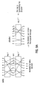
- encryption is usually placed between source coding and channel coding and decoding is performed separately as shown, for example, in Fig. 11A.
- the Source 100 outputs data which is compressed in a source code unit 102 after which an encryption in an encryption unit 104 is performed.
- channel coding is performed in a channel coding unit 106 before the channel encoded data is sent visa the channel 108. It is well-known that this separation principle does not hold in real-life communication as it postulates infinite block length.
- a first reference system 1 has a first encryption unit 110, which is fed by data originating from a source 100. The data stream output by the first encryption unit 110, is then fed into a unit in which a joint source-channel coding unit 112 without encryption is performed from which data is output to the channel 108.
- This first reference system 1 is shown in Fig. 11B.
- a second reference system 2 is shown in Fig. 11C.
- the second reference system 2 has a further encryption unit 114, which is implemented such that the data output from the joint source-channel coding unit 112 is fed into this further encryption unit 114, before the data output from the further encryption unit 114 is output on the channel.
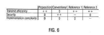
- reference system 1 (as shown in Fig. 11B) has a disadvantage concerning security aspects due to the fact that the joint source-channel coded signal is not encrypted.
- reference system 2 has a disadvantage concerning the implementation complexity as the further encryption unit 114 has to be implemented requiring further hardware space or numerical complexity.
- CRC cyclic redundancy check
- the puncture signal is then on the one hand transmitted via the channel into a turbo decoder of a receiver and, on the other hand, to a turbo decoder in the transmitter itself.
- An output from the turbo decoder of the transmitter is fed into a check unit which is furthermore provided with the signal output by the CRC-appending unit.
- the check unit can then check whether it is possible to reconstruct the signal U N , that is, whether the puncturing unit has punctured sufficiently less information from the turbo-encoded signal such that a signal reconstruction can be performed on the basis of the punctured signal.
- the turbo decoder of the receiver is coupled to the check unit of the transmitter via an acknowledged signal ACK. If information is lost during the transmit procedure via the channel (for example due to channel noise) it might be possible that the punctured signal does not include enough information such that the turbo decoder can completely recover the CRC-appendant signal U N .
- the turbo decoder of the receiver can be configured such that an acknowledge signal is not sent to the check-unit of the transmitter.
- the check unit can be configured such that it sends a signal to the puncturing unit to transmit further data to the turbo decoder of the receiver which was punctured in a previous step.
- the turbo decoder of the receiver is provided with further (redundant) information in order to increase the probability that the turbo decoder of the receiver works properly and decodes the received information correctly.
- the approach as disclosed in Fig. 12 has also the disadvantage that the transmitted signal is not secure because an encryption is not carried out or at least the redundant information included to the transmitted signal by the turbo encoder can be used by a possible attacker to crack the encryption.
- the present invention provides a communication apparatus for providing an encrypted output sequence of information units comprising:
- the present invention provides a method for providing an encrypted output sequence of information units comprising the following step:
- the present invention provides a communication apparatus for providing an output sequence of information units comprising:
- the present invention provides a method for providing an output sequence of information units comprising:
- the present invention is based on the finding that an improvement in security of data to be transmitted can be realized by applying an encrypter behind a redundancy encoder in a communication apparatus wherein the encrypter has a sequence manipulator which is operative to manipulate an order of information units or to eliminate selected information units in response to a secret encryption key.
- the encrypter can, for example, include an interleaver block which is filled with data according to a mapping scheme wherein the mapping scheme can be kept secret such that the mapping scheme is a secret encryption key.
- the information unit sequence which was fed into the interleaver block is then encrypted "secretly" as the mapping scheme or filling scheme of the interleaver block or storage block is not known publicly but only by an intended recipient who shall be able to decrypt the message.
- a puncturing is additionally applied on such an interleaver block it can be said that if, for example, the last column is punctured, the punctured information units are spread throughout the whole information units stored in the interleaver block, as the write-in scheme of the interleaver block is secret and thus it is not predictable for a person not knowing the secret key where the punctured bits or information units will occur or will be have to written in an deinterleaver block. Furthermore, if such an interleaved and punctured sequence is transmitted, it is only possible to reconstruct the original message if the secret key, that is, in the present example, the secret filling scheme for the interleaver block, is known at the receiver.
- the security for data transmission can be increased while still maintaining a transmit efficiency due to the puncturing of the redundancy encoded data.
- the implementation complexity can be kept low as only the encrypter with the sequence manipulator is provided which can, for example, be realized by providing the interleaving block and a control unit for filling the interleaving block according to the secret key.
- the present invention can also be implemented if just a manipulation rule for a secret key is known which would then result in a kind of "scrambling" of the data provided by the encrypter. If a receiver is also not informed about a scrambling rule according to which the input data for the encrypter was scrambled, it is also nearly impossible to reconstruct the original encoded output sequence of information units.
- the present invention can also be implemented such that the encoded output sequence of information units is just rearranged, that is, the position of the information units in the encoded output sequence is changed according to the secret encryption key. Then, it is only possible for a receiver to decrypt a thus encrypted message if a decryption key is known which corresponds to the secret encryption key. Furthermore, it is also possible to use a puncturing scheme as a secret encryption key such that special information units of the encoded output sequence are punctured when the encrypted output sequence of information units is formed. If a receiver then has no knowledge which of the received information units are punctured, or on which positions a puncturing was carried out, it is nearly impossible for the receiver to decrypt the correct message which was transmitted. Thus, it is not always necessary to use an interleaver or a storage block and a column-wise puncturing in order to encrypt an input information signal to obtain the encrypted output sequence of information units.
- the present invention provides the advantage that the security of a data transmission can be significantly increased with respect to known data transmission systems while keeping a high transmission efficiency. Furthermore, the proposed approach for increasing the security of a transmission has a moderate additional implementation complexity such that an implementation of the present invention only requires a low additional effort.
- Fig. 1 shows a block diagram of a first embodiment of the inventive communication apparatus for providing an encrypted output sequence of information units.
- the communication apparatus comprises a source 100, an encryption unit 102 and a unit for joint source-channel coding with encryption 120 from which the data is transmitted to a channel 108.
- the first embodiment of the invention is aimed to perform all three tasks, namely the source coding, the channel coding and the encryption, jointly, which is carried out in the joint source-channel coding unit 120 with encryption.
- encryption is placed between source coding and channel coding and the coding is performed separately. It is well-known that this separation principle does not hold in real-life communication schemes as it postulates infinite block length.
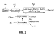
- a common key management unit 1 to 2 is disclosed by which an extension of the system structure as disclosed in Fig. 1 can be realised.
- a key generator 124 can create keys for the first encryption unit 102 and another for this encryption in the joint source-channel coding unit 120. By doing this, it is initialized by a primary key 126 as shown in Fig. 2.
- Such a common key management unit 122 provides the advantage that, for example, just the one time pad has to be stored as a (secret) primary key so that the key generator itself can generate keys for the first encryption unit 102 and the encryption stage in the joint source-channel coding unit 120.
- a primary key 126 can be used by different encryption algorithms thus increasing the security of such encrypted messages.
- a coupling of secret keys for different encryption units or encryption stages can easily be performed, for example, in that the key generator 124 generates a "long" secret key which can be divided in different sections wherein, for example, a first section is used as an encryption key for the encryption unit 102 whereas another part of the key generated by the key generator 124 can be used as a secret encryption key for the joint source-channel coding unit 120.
- joint source-channel coding enclosing an encryption stage as it is performed by the joint source-channel coding unit 120 provides the advantage that the source coding, the channel coding and the encryption are performed jointly.
- joint source-channel coding outperforms conventional separated transmission schemes for finite block lengths
- the inventive approach furthermore integrates the encryption on the one hand before the joint source-channel coding part and furthermore uses the interleaver of the puncturing scheme as a second security instance.
- this second security instance shall be described now in more detail as it can be said that this second security instance is the original inventive approach in the narrower sense.
- FIG. 3A a block diagram of a communication apparatus for providing an encrypted output sequence of information units is disclosed.
- This communication apparatus which is denoted by the reference numeral 120, is specially designed for use in a transmitter unit.
- the communication apparatus comprises a redundancy encoder 200 and an encrypter 202, the encrypter 202 having a sequence manipulator 204.
- An input information signal is fed via an input of the redundancy encoder 200 into the redundancy encoder 200 which transforms the input information signal, respectively information units included to the input information signal into an encoded output sequence which is output via an output of the redundancy encoder 200.
- the encoded output sequence comprises information units having information of the input information signal and redundant information such that it can be said that the encoded output sequence is a channel-encoded signal.
- the encoded output sequence is then fed into an encrypter 202 having said sequence manipulator 204 which then encrypts the encoded output sequence into an encrypted output sequence.
- the encrypted output sequence is then output via an output of the encrypter 202.
- the sequence manipulator 204 is configured to manipulate an order of information unit or to eliminate selected information unit to obtain the encrypted output sequence of information units wherein the manipulation of an order of the information unit or the elimination of selected information unit is carried out in response to a secret encryption key wherein the secret encryption key is only known to an intended recipient of the input information signal.
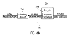
- Fig. 3B shows a block diagram of a communication apparatus which can be used in a receiver.
- the communication apparatus which 220 is provided with an encrypter input sequence which, for example, is received via the channel.
- the encrypted input sequence is then fed into a decrypter 250 having a sequence manipulator 252.
- the decrypter 250 with the sequence manipulator 252 is configured to decrypt the encrypted input sequence in order to receive an encoded input sequence which then is provided via an output of the decrypter 250 to an input of a redundancy decoder 254.
- the redundancy decoder 254 is then configured to decode the encoded input sequence into an output information signal output at an output of the redundancy decoder 254.
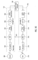
- Fig. 3C shows a block diagram of a communication system having a transmitter and receiver wherein the transmitter has a communication apparatus 120 according to an embodiment of the present invention and wherein the receiver has a communication apparatus 220 according to another embodiment of the present invention.
- the transmitter has a source 300 for providing date U to a first encryption unit 102 which carries out a first encryption unit 102.
- the first encryption unit 302 appends provides this data to a CRC unit 302 which appends a CRC code to the encrypted data.
- the data appended with the CRC-data is then fed into a turbo encoder 304 which adds redundant information to the encrypted CRC-appended data in order to output encoded data X which is an encoded output sequence of information units.
- the encoded data X is then fed into an interleaver 306 which acts as a second encryption stage as mentioned above.
- the precise functioning of the interleaver 306 will be described in a subsequent section.
- the interleaver 306 outputs the interleaved data to a matrix puncturing unit 308 which performs a puncturing according to a puncturing scheme in order to reduce the redundant information included to the encrypted data in the turbo encoder 304.
- the data output from the matrix puncturing unit 308 is then considered to be an encrypted output sequence of information unit which can be transmitted via the communication channel 108 into a matrix filling unit 310 of the receiver.
- the matrix filling unit 310 is then a part of a communication apparatus 220 of the receiver, which is a further embodiment of the present invention.
- the matrix filling unit 310 adds data to the data received from the communication channel 108 in such a way that the puncturing carried out in the matrix puncturing unit 308 is reversed. Then, the matrix filling unit 310 outputs the data to a de-interleaver 312 which de-interleaves the data received from the matrix filling unit 310 according to a decryption key which corresponds to the encryption key for encrypting data in the interleaver 306. The de-interleaver 312 then outputs the de-interleaved data to a turbo decoder 314 which decodes the data Y in order to remove the redundant information used for channel coding purposes.
- the turbo decoder 314 then feeds the encoded data to a CRC unit 315 for checking the received data on correctness. If a CRC-check in the CRC-unit 315 has a positive result, an acknowledge signal ACK is output from the CRC-unit 315 and transmitted to the transmitter such that the transmitter can stop sending punctured information units to restore the transmitted signal.
- the functionality of the transmission system as shown in Fig. 3C is thus similar to the functionality of the system shown in Fig. 12.
- the CRC-checked signal then is passed to a decryption unit 316 which reverses the encryption carried out by the first encryption unit 102.
- the resulting data ⁇ is then provided to a sink 318.
- the source 100 provides, for example, a binary sequence U of length N-C.
- a CRC of length C is added to the encrypted message.
- the data (of length N) is encoded using a parallel concatenated turbo code with recursive systematic convolutional codes.
- the encoded message X of length K is obtained by discarding some systematic bits (this portion is determined by the entropy of the source and handeled as a design parameter of the transmission scheme) and concatenating the parity bits. It was shown that compression should be achieved by puncturing the parity bits randomly.
- a data transmission system in which the parity message is also interleaved and the columns (with length sqrt(K) of the square matrix are sent to the receiver segment-wise until the transmitter gets an acknowledgment signal (for example an ACK bit) from the receiver.
- the receiver stores the received noisy message into the appropriate column of the matrix, pads the positions where no parity bits are available at this time with a soft value of 0 (no information for this bit) and de-interleaves the complete message resulting in the message denoted by the variable Y.
- a turbo decoder is used to fill all unknown gaps. Together with the description of the conventional cipher the turbo decoder reconstructs the message ⁇ of length N-C.
- the transmission of different parity columns is performed until an integrity test (i.e. the CRC test) is passed successfully. Then the receiver sends an ACK signal (for example an ACK bit) to the transmitter and the transmitter stops sending extra parity bits. If the channel is very noisy, columns can be retransmitted and code combining is performed.
- an integrity test i.e. the CRC test
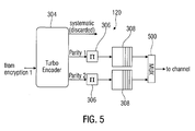
- FIG. 3D another embodiment of a communication system is shown, using further embodiments of the inventive communication apparatus.
- the system as shown in Fig. 3D also discloses a source 300, a CRC-appending unit 302 and a Turbo Encoder 304.
- the Turbo Encoder 304 provides a systematic information unit sequence, a first and a second parity information unit sequence.
- the systematic information unit sequence is discarded for the further processing of the signal.
- the first and second parity information unit sequences are fed into the interleaver 306, which provides a first and second interleaver matrix 308.
- the first and second interleaver matrix 308 is punctured such that a first part A and A' (schematically) comprise information and the second part B and B' (schematically) comprise redundancy information which is punctured.
- the parts A and A' are fed to the multiplexer MUX 320 which assembles the two parts to be transmitted via the channel 108 to the Receiver. If the receiver is not able to reconstruct the sent data, an ACK signal is not sent to the transmitter (especially the controller) via an ARQ-channel, for example. In this instance, the transmitter, especially the controller feeds the parts B and B' to the multiplexer 320 to be transmitted via the channel 108.
- the controller can be configured to resent the parts A and A' such that a cyclic transmission of the parts A and A' and the parts B and B' results.
- This retransmission can also be extended to a three-fold division of the interleaver matrix 308 as shown in Fig. 3E. In such an instance, the transmission of first the "A-parts", then the "B-parts” and finally the "C-parts" are transmitted, before the controller again starts to send the A-parts. If the controller in the transmitter receives an ACK-signal from the receiver, then it stops transmission of parts of the interleaver matrix 308.
- the encryption 1 as carried out, for example, in the first encryption unit 102, it is suggested to use a standard cipher in order to encrypt the source message before turbo-encoding. On the receiver side, this operation is reversed after source-channel decoding using the iterative turbo decoder.
- this encryption mechanism can be implemented by using an interleaver of the random puncturing block as the secret key. If an attacker does not know the mapping of the interleaver, he is not able to re-sort the noisy parity bits. Furthermore, if an attacker also does not know which bits are actually interleaved, it is impossible to restore the originally encrypted message as denoted by the variable X. First decoding and restoring the message correctly (should) fail. Note that indeed there are N!
- mappings for a source sequence of length N, wherein the CRC bits are regarded as part of the source message
- some mappings lead to the same result. For example, if elements with value 0 are mapped to position with elements of value 0 and elements of value 1 are mapped to elements of value 1, then an attacker has found an equivalent key. In a subsequent section the issue of judging the probability that an attacker will find an equivalent key is discussed in more detail.
- FIG. 4 there are again shown the inventive communication apparatuses 120 of the transmitter and 220 of the receiver in the embodiments as shown in Fig. 3C.
- the FEC encoder provides, for example, a codeword of length 16 wherein the positions of the codeword are numbered in Fig. 4 by the numbers 1 to 16.
- the codeword in Fig. 4 can be considered to be the encoded output sequence X as disclosed in Fig. 3C.
- an interleaver 306 is applied which is operative in response to an interleaver rule to fill the codeword respectively the 16 information units of the codeword into an interleaver block of size 16, that is in an interleaver block having four rows and four columns.
- the scheme according to which the filling of the interleaver block will be carried out is the interleaver rule 306 which has to be kept a secret such that a recipient of the interleaved message who does not know the corresponding de-interleaver rule will not be able to restore the correct codeword.
- the interleaver rule for filling the interleaver block as shown in Fig. 4 can be used as a secret encryption key.
- a puncturing can be applied such as it is carried out in the matrix puncturing unit 308 as disclosed in Fig. 3C.
- the puncturing according to one embodiment is explained in more detail as, for example, the last two columns of C1 and C2 of the interleaver block are cancelled.
- the interleaver block can be read out, for example, column-wise, resulting in a message 400 as disclosed in Fig. 4.
- a secret write-in rule for filling the interleaver and a secret read-out rule for reading out the information stored in the interleaver block 400 such that an additional increase in security can be performed by the two-fold interleaver operation.
- an unknown puncturing scheme such that, for example, elements in a diagonal line of the interleaver block are punctured. If this puncturing scheme is also not known, it can be used as the secret encryption key, or, if used in combination with a secret write-in or read-out rule as an additional method for increasing the security of a thus encrypted message.
- the message 402 after puncturing and reading out the interleaver block 400 has a final position in which no information is included due to the puncturing.
- This final position that is, the last eight information units denoted by X, were not transmitted via the channel 108 in order to provide a compression of the data to be transmitted to increase transmit efficiency.
- a received message 404 can then be received, assuming that the channel 108 was ideal.
- the received message 404 can then be written in to a de-interleaver block 406 according to a write-in rule for said de-interleaver block 406.
- the write-in rule of the de-interleaver block 406 must correspond to the read-out rule of the interleaver block 400 in order to provide a filling pattern of the de-interleaver block 406 which corresponds to the filling pattern of the interleaver block 400 before a read-out operation on the interleaver block 400. Afterwards, a filling has to be carried out such that the interleaver block 406 having also four rows and four columns, is completely filled. This means with respect to the example shown in Fig. 4, that the last columns of the de-interleaver block 406 are, for example, filled with a value of 0 in order to fill all elements of the de-interleaver block 406.
- a secret de-interleaver rule is applied which has to be the inverse interleaver rule applied to fill the interleaver 400 with the information unit of the codeword.
- a decrypted word 408 can be obtained which can be fed into an FEC-decoder 314 as disclosed in Fig. 4.
- the same secret write-in rule or read-out rule or puncturing rule can also be applied to fill or read out the de-interleaver block 406.
- the interleaver block 400 and the de-interleaver block 406 use the interleaver as an encryption tool and the de-interleaver as decryption tool. Rather, if only the interleaving rule and the corresponding de-interleaving rule are known, it is possible to provide a scrambling in the encrypter such that the encrypted output sequence can be obtained without the use of an interleaver block. Equivalently, it is also possible not only to puncture column-wise but to puncture randomly wherein it is obviously necessary that the receiver has information about the puncturing scheme such that the receiver can reverse the puncturing.
- Fig. 5 another embodiment of the inventive communication apparatus for providing an encrypted sequence of information unit is shown.
- Each of the encryption paths has an interleaver 306 and a following matrix puncturing a unit 308 in order to provide an encrypted output sequence of information units for each of both paths.
- the encrypted output sequences of information units of both paths are then fed into a multiplexer 500 which forms a single stream of information units to be transmitted via the channel.
- the reason why the systematic bit sequence is discarded can be seen in the following facts that, first, a reduction of the redundancy of the source information is achieved and, secondly, the security level of the transmission can be increased.
- the two reasons are related to each other; if redundancy can be decreased, the security of the transmission can be increased because the redundancy reduction of the transmission means reduction of information for the cracking by the attacker.
- the inventive methods can be implemented in hardware or in software.
- the implementation can be performed using a digital storage medium, in particular a disk or a CD having electronically readable control signals stored thereon, which can cooperate with a programmable computer system such that the inventive methods are performed.
- the present invention is therefore a computer program product with a program code stored on a machine-readable carrier, the program code performing the inventive methods when the computer program runs on a computer.
- the inventive methods are therefore a computer program having a program code for performing the inventive methods, when the computer program runs on a computer.
- the inventive approach has several advantages in view of the conventional approach as shown in Fig. 11A or the two reference systems as shown in Fig. 11B and 11C.
- inventive approach (denoted as "proposition") has a significant advantage concerning the transmit efficiency with respect to the conventional system design.
- the inventive approach has significant advantages in view of the first reference system whereas the inventive approach has significant advantages concerning the implementation complexity in view of reference system 2.
- Fig. 7 in which the basic system design is disclosed in short.
- the turbo encoder then outputs a first and second bit sequence denoted as parity 1 and parity 2 respectively, wherein the systematic bit sequence is discarded.
- the data of each of the output parity 1 and parity 2 is then fed into a signal path as disclosed in the lower section of Fig. 7.
- Each of these paths has an interleaver (denoted by the Greek letter n followed by a puncturing matrix of the size N ⁇ N .
- Encryption is vulnerable to brute force attacks if the number of bits (respectively information units) which are transmitted over the channel is low. If a perfect channel is assumed without any noise, only H ⁇ N bits have to be known at the receiver in order to reconstruct the source message perfectly in which variable H denotes the entropy of the source and N denotes the length of the source message. It has to be noted that the worst case of data transmission is reflected in the turbo compression scenario. Thus, it has to be mentioned that, in order to compensate a noisy channel, more redundant information has to be transmitted such that an attack on the encryption key is much easier. However, as the noisy channel also eliminates information transmitted from the transmitter to the receiver, it can be said that both effects compensate such that the further increase in security is not always necessary for noisy channels. However, a more detailed analysis of the probability to crack the encryption key shall be based on the above-mentioned worst case scenario.
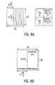
- Fig. 8A the division of the interleaver block is explained in more detail.
- a puncturing can be performed such that columns are erased from the right-hand side of the interleaver block in order to reduce the redundancy.
- the probability of values 0 and 1 in the information comprising a part of the interleaver block can by the formula H ⁇ N/4 wherein the value for the erased value 0 and 1 in the right-hand side part of the interleaver block can be calculated by the formula N(2-H)/4.
- n denotes the interleaver which is a function of the one-time pad or primary key.
- the bits are schematically grouped together into information bits and redundant bits. The latter bits are punctured and do not have to be transmitted (if a perfect channel is assumed). Accordingly, the probability of guessing the secret or an equivalent interleaver (secret encryption key) depends on the number of bits carrying information, i.e. it depends on the entropy H of the source and the block length N and is very low for medium to long blocks. Thus, it can be said that the probability of a successful attack carried out by a brute force attack, is equal to the probability of knowing the key or an equivalent key.
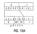
- Fig. 9A and 9B is made for the calculation of the probability of finding such an equivalent key.
- Fig. 9A the finding of such an equivalent key is shown.
- a parity bit sequence is shown which is encrypted by key 1 into a sequence which can be sent via the channel.
- a decryption key which is the inverse key 1
- a puncturing is applied before sending the bit sequence (which is denoted by the variable E 0 and E 1 the decrypted sequence also contains erasures wherein the value of this erasure or erased position can be recreated by the turbo decoder.
- E 0 and E 1 the decrypted sequence also contains erasures wherein the value of this erasure or erased position can be recreated by the turbo decoder.
- FIG. 9A it is shown how a key to, respectively an inverse key 2 can be guessed by an attacker such that the attacker can restore the original message.
- the attacker can use the message which was sent via the channel and obtain the correct decrypted sequence unless he uses a key which is different from the secret encryption key. Therefore, it has to be noted that there are several keys which provide a correct de-mapping but which are based on completely different mapping rules.
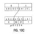
- Fig. 9B such an equivalent key is shown which results in the same encryption and decryption result than the original correct secret encryption key does. This is due to the fact that the equivalent key also maps values of 0 to values of 0 or erasures and values of 1 to values of 1 or erasures. Thus, if such a mapping has been found, an equivalent key has been found.
- ⁇ denotes the number of mappings to the erasure area (e to h).
- a mapping according to Fig. 10C also has taken into consideration whereas now the value of 1 can be mapped from position G to L onto positions e to 1.
- a general approach of calculating the probability of finding a equivalent key can be done using the scheme in Fig. 10D which is equivalent to lower part of Figs. 10A and 10C, now including information about the entropy and the length of the information sequence.
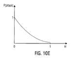
- the probability of a successful attack is 1 if the entropy approach is zero, that is if the source block is completely redundant. With an increase of the entropy a decrease of the probability of a successful attack can be observed.
- the probability of a brute force attack is upper-bounded by 2 ⁇ 2 (-NH/2) .
- This probability corresponds to a brute force attack on DES (symmetric cipher) with a key length of 199 bit!
- the proposed inventive approach provides high security if the channel is very noisy. In this case many parity bits have to be transmitted and the receiver has to resort the noise soft information. With knowledge of the interleaver, which is exemplarily used, these bits or information units are sorted incorrectly and thus turbo decoding fades with high probability. In order to resort the parity bits or information units correctly, the unique interleaver has to be known. However, the probability of guessing this interleaver or interleaving rule or secret key is 1/N!.
Priority Applications (2)
| Application Number | Priority Date | Filing Date | Title |
|---|---|---|---|
| EP05011011A EP1724933A1 (fr) | 2005-05-20 | 2005-05-20 | Dispositif de communication et procédé de chiffrement de données |
| JP2006141732A JP4550005B2 (ja) | 2005-05-20 | 2006-05-22 | 情報ユニットの暗号化配列を提供する通信装置及び方法 |
Applications Claiming Priority (1)
| Application Number | Priority Date | Filing Date | Title |
|---|---|---|---|
| EP05011011A EP1724933A1 (fr) | 2005-05-20 | 2005-05-20 | Dispositif de communication et procédé de chiffrement de données |
Publications (1)
| Publication Number | Publication Date |
|---|---|
| EP1724933A1 true EP1724933A1 (fr) | 2006-11-22 |
Family
ID=34936777
Family Applications (1)
| Application Number | Title | Priority Date | Filing Date |
|---|---|---|---|
| EP05011011A Withdrawn EP1724933A1 (fr) | 2005-05-20 | 2005-05-20 | Dispositif de communication et procédé de chiffrement de données |
Country Status (2)
| Country | Link |
|---|---|
| EP (1) | EP1724933A1 (fr) |
| JP (1) | JP4550005B2 (fr) |
Cited By (7)
| Publication number | Priority date | Publication date | Assignee | Title |
|---|---|---|---|---|
| CN102868478A (zh) * | 2011-07-07 | 2013-01-09 | 中国科学院研究生院 | 联合信道安全编码中的Turbo码删余器设计方法 |
| CN103107816A (zh) * | 2011-11-15 | 2013-05-15 | 中国科学院研究生院 | 联合信道安全编码中的Turbo码复用器设计方法 |
| DE102012003968A1 (de) * | 2012-02-29 | 2013-08-29 | Giesecke & Devrient Gmbh | Gegen Ausspähen geschützte Berechnung |
| CN103475462A (zh) * | 2012-06-07 | 2013-12-25 | 中国科学院研究生院 | 基于随机调制的联合信道与安全编译码设计方法 |
| CN104539416A (zh) * | 2014-11-04 | 2015-04-22 | 中国石油大学(华东) | 一种基于新型交织技术的密钥流生成方法及装置 |
| CN104871492A (zh) * | 2012-12-20 | 2015-08-26 | 丰田自动车株式会社 | 通信系统、通信装置以及通信方法 |
| US9237008B2 (en) | 2011-07-25 | 2016-01-12 | Mitsubishi Electric Corporation | Encryption device, encryption method, and encryption program |
Families Citing this family (1)
| Publication number | Priority date | Publication date | Assignee | Title |
|---|---|---|---|---|
| US20080317243A1 (en) * | 2007-03-30 | 2008-12-25 | Ramprashad Sean A | Low complexity encryption method for content that is coded by a rateless code |
Family Cites Families (2)
| Publication number | Priority date | Publication date | Assignee | Title |
|---|---|---|---|---|
| JPH0697832A (ja) * | 1992-09-14 | 1994-04-08 | Matsushita Electric Ind Co Ltd | 符号変換回路およびそれを備えたa/d変換器 |
| JPH088898A (ja) * | 1994-06-17 | 1996-01-12 | Nippon Motorola Ltd | 暗号化装置 |
-
2005
- 2005-05-20 EP EP05011011A patent/EP1724933A1/fr not_active Withdrawn
-
2006
- 2006-05-22 JP JP2006141732A patent/JP4550005B2/ja not_active Expired - Fee Related
Non-Patent Citations (6)
| Title |
|---|
| DÜTSCH N, HAGENAUER J: "Combined Incremental and Decremental Redundancy in Joint Source-Channel Coding", INTERNATIONAL SYMPOSIUM ON INFORMATION THEORY AND ITS APPLICATIONS, ISITA2004, 10 October 2004 (2004-10-10), Parma, Italy, pages 1 - 5, XP002343373, Retrieved from the Internet <URL:http://www.lnt.e-technik.tu-muenchen.de/mitarbeiter/duetsch/work/papers/duetsch-isita04.pdf> [retrieved on 20050902] * |
| HAGENAUER J ET AL: "Incremental and decremental redundancy in turbo source-channel coding", CONTROL, COMMUNICATIONS AND SIGNAL PROCESSING, 2004. FIRST INTERNATIONAL SYMPOSIUM ON HAMMAMET, TUNISIA MARCH 21-24, 2004, PISCATAWAY, NJ, USA,IEEE, 21 March 2004 (2004-03-21), pages 595 - 598, XP010705558, ISBN: 0-7803-8379-6 * |
| N. DÜTSCH; J. HAGENAUER: "Combined incremental and decremental redundancy in joint source-channel coding", INTERNATIONAL SYMPOSIUM ON INFORMATION THEORY AND ITS APPLICATION , ISITA 2004, 10 October 2004 (2004-10-10) |
| N. DÜTSCH; J. HAGENAUER: "Combined incremental and decremental redundancy in joint source-channel coding", INTERNATIONAL SYMPOSIUM ON INFORMATION THEORY AND ITS APPLICATION, ISITA 2004, 10 October 2004 (2004-10-10) |
| STIG FRODE MJOLSNES: "MODELING A GENERAL COMMUNICATION SYSTEM DOES CRYPTOGRAPHY MAKE A DIFFERENCE?", PROCEEDINGS OF THE WORLD MULTICONFERENCE ON SYSTEMICS, CYBERNETICS AND INFORMATICS, vol. 15, 14 July 2002 (2002-07-14), Orlando, Florida, USA, pages 436 - 440, XP008049777 * |
| YUAN DONG FENG; ZHANG LI JUN: "A novel scheme combining interleaving technique with cipher in Rayleigh fading channels", ICCT'98. 1998 INTERNATIONAL CONFERENCE ON COMMUNICATION TECHNOLOGY., vol. 2, 22 October 1998 (1998-10-22), Beijing, China, pages S47-02-1 - S47-02-4, XP002343372, ISBN: 7-80090-827-5 * |
Cited By (10)
| Publication number | Priority date | Publication date | Assignee | Title |
|---|---|---|---|---|
| CN102868478A (zh) * | 2011-07-07 | 2013-01-09 | 中国科学院研究生院 | 联合信道安全编码中的Turbo码删余器设计方法 |
| US9237008B2 (en) | 2011-07-25 | 2016-01-12 | Mitsubishi Electric Corporation | Encryption device, encryption method, and encryption program |
| CN103107816A (zh) * | 2011-11-15 | 2013-05-15 | 中国科学院研究生院 | 联合信道安全编码中的Turbo码复用器设计方法 |
| DE102012003968A1 (de) * | 2012-02-29 | 2013-08-29 | Giesecke & Devrient Gmbh | Gegen Ausspähen geschützte Berechnung |
| CN103475462A (zh) * | 2012-06-07 | 2013-12-25 | 中国科学院研究生院 | 基于随机调制的联合信道与安全编译码设计方法 |
| CN104871492A (zh) * | 2012-12-20 | 2015-08-26 | 丰田自动车株式会社 | 通信系统、通信装置以及通信方法 |
| EP2938015A4 (fr) * | 2012-12-20 | 2015-10-28 | Toyota Motor Co Ltd | Système de communication, unité de communication, et procédé de communication |
| US9392449B2 (en) | 2012-12-20 | 2016-07-12 | Toyota Jidosha Kabushiki Kaisha | Communication system, communication unit, and communication method |
| CN104871492B (zh) * | 2012-12-20 | 2016-10-26 | 丰田自动车株式会社 | 通信系统、通信装置以及通信方法 |
| CN104539416A (zh) * | 2014-11-04 | 2015-04-22 | 中国石油大学(华东) | 一种基于新型交织技术的密钥流生成方法及装置 |
Also Published As
| Publication number | Publication date |
|---|---|
| JP4550005B2 (ja) | 2010-09-22 |
| JP2007020151A (ja) | 2007-01-25 |
Similar Documents
| Publication | Publication Date | Title |
|---|---|---|
| EP1724933A1 (fr) | Dispositif de communication et procédé de chiffrement de données | |
| US8151174B2 (en) | Block modulus coding (BMC) systems and methods for block coding with non-binary modulus | |
| US8176403B2 (en) | Distributed block coding (DBC) | |
| US6732316B1 (en) | Data interleaver and method of interleaving data | |
| EP1538757B1 (fr) | Adaptation de débit et entrelacement de canal pour un système de communication | |
| US7924763B2 (en) | Method and appratus for rate matching within a communication system | |
| EP2181505B1 (fr) | Code multicouche de contrôle par redondance cyclique dans un système de communications sans fil | |
| US7475330B2 (en) | Method and apparatus for generating a punctured symbol vector for a given information vector | |
| US9496897B1 (en) | Methods and apparatus for generating authenticated error correcting codes | |
| EP0966126B1 (fr) | Codeur de parole effectuant un chiffrage | |
| EP2111703B1 (fr) | Procédé de génération de sous-paquets à index binaire adaptatif | |
| US9203608B2 (en) | System for encrypting data with an error correction code | |
| CN1124718C (zh) | 加密通信系统中重发数据的解密 | |
| JP5679059B2 (ja) | 無線送受信装置、通信システム及びそれらに用いるチャネルコーディング処理方法 | |
| JP2007020151A6 (ja) | 情報ユニットの暗号化配列を提供する通信装置及び方法 | |
| EP3306844B1 (fr) | Appareil et procédé de transmission de données basés sur la protection inégale contre les erreurs | |
| US20020018561A1 (en) | Data encryption and decryption using error correction methodologies | |
| JP2002527982A (ja) | 符号化または復号化方法および符号化または復号化装置 | |
| US6442728B1 (en) | Methods and apparatus for turbo code | |
| JP2011254459A (ja) | ワイヤレス遠隔通信システムのためのパケットを安全に伝送する方法 | |
| JP2009533796A (ja) | 消失支援ブロックコードデコーダおよびこれに関する方法 | |
| Harada et al. | Some restrictions on weight enumerators of singly even self-dual codes | |
| CN110266321A (zh) | 一种新的基于极化码的通信方法及系统 | |
| EP3654576A1 (fr) | Procédé mis en uvre par ordinateur pour le codage de correction d'erreur et le chiffrement d'un fichier | |
| RU2755055C1 (ru) | Способ передачи многоблочных сообщений каскадным кодом [PC (32, 16, 17), БЧХ (31, 16, 7)] |
Legal Events
| Date | Code | Title | Description |
|---|---|---|---|
| PUAI | Public reference made under article 153(3) epc to a published international application that has entered the european phase |
Free format text: ORIGINAL CODE: 0009012 |
|
| 17P | Request for examination filed |
Effective date: 20060512 |
|
| AK | Designated contracting states |
Kind code of ref document: A1 Designated state(s): AT BE BG CH CY CZ DE DK EE ES FI FR GB GR HU IE IS IT LI LT LU MC NL PL PT RO SE SI SK TR |
|
| AX | Request for extension of the european patent |
Extension state: AL BA HR LV MK YU |
|
| AKX | Designation fees paid |
Designated state(s): DE GB |
|
| STAA | Information on the status of an ep patent application or granted ep patent |
Free format text: STATUS: THE APPLICATION HAS BEEN WITHDRAWN |
|
| 18W | Application withdrawn |
Effective date: 20120529 |