EP1724870A1 - Solid oxide fuel cell and method of manufacturing the same - Google Patents
Solid oxide fuel cell and method of manufacturing the same Download PDFInfo
- Publication number
- EP1724870A1 EP1724870A1 EP06252613A EP06252613A EP1724870A1 EP 1724870 A1 EP1724870 A1 EP 1724870A1 EP 06252613 A EP06252613 A EP 06252613A EP 06252613 A EP06252613 A EP 06252613A EP 1724870 A1 EP1724870 A1 EP 1724870A1
- Authority
- EP
- European Patent Office
- Prior art keywords
- roughened surface
- oxide fuel
- roughness
- solid oxide
- fuel cell
- Prior art date
- Legal status (The legal status is an assumption and is not a legal conclusion. Google has not performed a legal analysis and makes no representation as to the accuracy of the status listed.)
- Withdrawn
Links
Images




Classifications
-
- H—ELECTRICITY
- H01—ELECTRIC ELEMENTS
- H01M—PROCESSES OR MEANS, e.g. BATTERIES, FOR THE DIRECT CONVERSION OF CHEMICAL ENERGY INTO ELECTRICAL ENERGY
- H01M4/00—Electrodes
- H01M4/86—Inert electrodes with catalytic activity, e.g. for fuel cells
- H01M4/88—Processes of manufacture
- H01M4/8878—Treatment steps after deposition of the catalytic active composition or after shaping of the electrode being free-standing body
- H01M4/8882—Heat treatment, e.g. drying, baking
- H01M4/8885—Sintering or firing
-
- H—ELECTRICITY
- H01—ELECTRIC ELEMENTS
- H01M—PROCESSES OR MEANS, e.g. BATTERIES, FOR THE DIRECT CONVERSION OF CHEMICAL ENERGY INTO ELECTRICAL ENERGY
- H01M4/00—Electrodes
- H01M4/86—Inert electrodes with catalytic activity, e.g. for fuel cells
- H01M4/8605—Porous electrodes
- H01M4/8621—Porous electrodes containing only metallic or ceramic material, e.g. made by sintering or sputtering
-
- H—ELECTRICITY
- H01—ELECTRIC ELEMENTS
- H01M—PROCESSES OR MEANS, e.g. BATTERIES, FOR THE DIRECT CONVERSION OF CHEMICAL ENERGY INTO ELECTRICAL ENERGY
- H01M4/00—Electrodes
- H01M4/86—Inert electrodes with catalytic activity, e.g. for fuel cells
- H01M4/8605—Porous electrodes
- H01M4/8626—Porous electrodes characterised by the form
-
- H—ELECTRICITY
- H01—ELECTRIC ELEMENTS
- H01M—PROCESSES OR MEANS, e.g. BATTERIES, FOR THE DIRECT CONVERSION OF CHEMICAL ENERGY INTO ELECTRICAL ENERGY
- H01M8/00—Fuel cells; Manufacture thereof
- H01M8/10—Fuel cells with solid electrolytes
- H01M8/12—Fuel cells with solid electrolytes operating at high temperature, e.g. with stabilised ZrO2 electrolyte
- H01M8/1213—Fuel cells with solid electrolytes operating at high temperature, e.g. with stabilised ZrO2 electrolyte characterised by the electrode/electrolyte combination or the supporting material
-
- H—ELECTRICITY
- H01—ELECTRIC ELEMENTS
- H01M—PROCESSES OR MEANS, e.g. BATTERIES, FOR THE DIRECT CONVERSION OF CHEMICAL ENERGY INTO ELECTRICAL ENERGY
- H01M8/00—Fuel cells; Manufacture thereof
- H01M8/10—Fuel cells with solid electrolytes
- H01M8/12—Fuel cells with solid electrolytes operating at high temperature, e.g. with stabilised ZrO2 electrolyte
- H01M8/124—Fuel cells with solid electrolytes operating at high temperature, e.g. with stabilised ZrO2 electrolyte characterised by the process of manufacturing or by the material of the electrolyte
- H01M8/1246—Fuel cells with solid electrolytes operating at high temperature, e.g. with stabilised ZrO2 electrolyte characterised by the process of manufacturing or by the material of the electrolyte the electrolyte consisting of oxides
-
- H—ELECTRICITY
- H01—ELECTRIC ELEMENTS
- H01M—PROCESSES OR MEANS, e.g. BATTERIES, FOR THE DIRECT CONVERSION OF CHEMICAL ENERGY INTO ELECTRICAL ENERGY
- H01M4/00—Electrodes
- H01M4/86—Inert electrodes with catalytic activity, e.g. for fuel cells
- H01M4/90—Selection of catalytic material
- H01M4/9016—Oxides, hydroxides or oxygenated metallic salts
- H01M4/9025—Oxides specially used in fuel cell operating at high temperature, e.g. SOFC
-
- Y—GENERAL TAGGING OF NEW TECHNOLOGICAL DEVELOPMENTS; GENERAL TAGGING OF CROSS-SECTIONAL TECHNOLOGIES SPANNING OVER SEVERAL SECTIONS OF THE IPC; TECHNICAL SUBJECTS COVERED BY FORMER USPC CROSS-REFERENCE ART COLLECTIONS [XRACs] AND DIGESTS
- Y02—TECHNOLOGIES OR APPLICATIONS FOR MITIGATION OR ADAPTATION AGAINST CLIMATE CHANGE
- Y02E—REDUCTION OF GREENHOUSE GAS [GHG] EMISSIONS, RELATED TO ENERGY GENERATION, TRANSMISSION OR DISTRIBUTION
- Y02E60/00—Enabling technologies; Technologies with a potential or indirect contribution to GHG emissions mitigation
- Y02E60/30—Hydrogen technology
- Y02E60/50—Fuel cells
-
- Y—GENERAL TAGGING OF NEW TECHNOLOGICAL DEVELOPMENTS; GENERAL TAGGING OF CROSS-SECTIONAL TECHNOLOGIES SPANNING OVER SEVERAL SECTIONS OF THE IPC; TECHNICAL SUBJECTS COVERED BY FORMER USPC CROSS-REFERENCE ART COLLECTIONS [XRACs] AND DIGESTS
- Y02—TECHNOLOGIES OR APPLICATIONS FOR MITIGATION OR ADAPTATION AGAINST CLIMATE CHANGE
- Y02P—CLIMATE CHANGE MITIGATION TECHNOLOGIES IN THE PRODUCTION OR PROCESSING OF GOODS
- Y02P70/00—Climate change mitigation technologies in the production process for final industrial or consumer products
- Y02P70/50—Manufacturing or production processes characterised by the final manufactured product
Definitions
- the present invention relates to a solid oxide fuel cell and a method of manufacturing the same.
- a solid oxide fuel cell undergoes an electrode reaction at a three-phase interface of a solid electrolyte, an electrode and a gas phase.
- a joint surface which is sometimes referred to as an effective interface area
- the enlargement of the effective interface area between the solid electrolyte and the electrode also improves the mechanical joint strength between the solid electrolyte and the electrode.
- a surface of an electrolyte is roughened so as to form roughness on the surface (as described, for example, in JP-A-7-073890 ).
- Themethod for forming the roughened surface includes a coarse particle applying method, a sandpaper pressing method and a sand blasting method.
- Such a method has been also proposed that a roughened surface is formed by making coarse particles present only on a part of an electrode, which is in contact with a solid electrolyte, but not present on the other parts thereof, by a slurry method or a thermal spraying method (as described, for example, in Japanese Patent No. 2,695,641 ).
- Fig. 8 is a schematic cross sectional view showing a roughened surface of a solid electrolyte formed by the related methods for forming a roughened surface.
- a roughened surface can be formed on a solid electrolyte 51, for example, by a sandblastingmethod, repetition frequency of roughness on the roughened surface (which is sometimes referred to as a roughness frequency) is almost constant as shown in the figure.
- repetition frequency of roughness on the roughened surface (which is sometimes referred to as a roughness frequency) is almost constant as shown in the figure.
- a roughness frequency repetition frequency of roughness on the roughened surface
- improvement in electric power generation performance of a fuel cell is also limited.
- the present invention has been made in view of the above circumstances, and provides a solid electrolyte fuel cell in which an area of a joint surface between a solid electrolyte and an electrode is further enlarged so as to improve electric power generation performance thereof, and a method of manufacturing the solid electrolyte fuel cell.
- a solid oxide fuel cell comprising:
- the roughened surface may include:
- the second type of the surface roughness may be finer in roughness than the first type of the surface roughness.
- At least one of the solid electrolyte and the electrodes may be generated by sintering a green sheet which is used in a green sheet sintering process and on which a pattern of the roughened surface is formed by being pressed with a pattern mold.
- the effective interface area of the joint surface between the solid electrolyte and the electrode in a solid oxide fuel cell may be further enlarged so as to improve the electric power generation performance of the solid oxide fuel cell.
- the enlargement of the effective interface area between the solid electrolyte and the electrode also improves the mechanical joint strength between the solid electrolyte and the electrode.
- Such a solid oxide fuel cell that has an enlarged effective interface area can be produced at low cost.
- a solid oxide fuel cell including a solid electrolyte having electrodes on both surfaces thereof, the method comprising:
- Fig. 1 is a schematic cross sectional view showing a solid oxide fuel cell according to an embodiment of the invention.
- Fig. 2 is a schematic enlarged cross sectional view showing the roughened surface of the solid electrolyte of the solid oxide fuel cell shown in Fig. 1.
- a solid oxide fuel cell 1 including a solid electrolyte 11 having electrodes 12 and 13 on both surfaces thereof, at least one of joint surfaces where the solid electrolyte 11 and the electrodes 12 and 13 are in contact with each other is a roughened surface having at least two surface roughnesses different fromeach other.
- roughened surfaces are formed on both surfaces of the solid electrolyte 11.
- such a roughened surface is formed that is a roughened surface having a first surface roughness, on which a roughened surface having a second surface roughness is formed.
- the second surface roughness is finer than the first surface roughness.
- the joint surfaces between the solid electrolyte 11 and the electrodes 12 and 13 each has a roughness structure having at least two roughness frequencies different from each other, and the roughness structure has a first roughness structure having a relatively large roughness frequency and a second roughness structure having a relatively small roughness frequency formed on the first roughness structure.
- the solid electrolyte 11 in the embodiment is generated with a green sheet used in the green sheet sintering method by sintering the green sheet having the roughened surface formed by pressing a pattern mold thereon.
- the pattern mold has a roughened surface being a mold of the roughened surface to be formed on the green sheet.
- the roughened surface on the pattern mold has a roughened surface having a first surface roughness, on which a roughened surface having a second surface roughness is formed, and the second surface roughness is finer than the first surface roughness.
- the pattern mold has a roughness structure having at least two roughness frequencies different from each other corresponding to the roughness structure to be formed on the green sheet, and the roughness structure on the pattern mold has a first roughness structure having a relatively large roughness frequency and a second roughness structure having a relatively small roughness frequency formed on the first roughness structure.
- the pattern mold having a roughened surface having the first surface roughness, on which a roughened surface having the second surface roughness is formed is formed of a fabric material woven with inorganic fibers, organic fibers or thin metal wires, or a metallic member having a surface shape transferred from a fabric material woven with inorganic fibers, organic fibers or thin metal wires.
- the method of manufacturing a solid oxide fuel cell according to an embodiment of the invention roughly includes two process steps: a transferring step of transferring a roughened surface of a pattern mold onto at least one surface of a green sheet used in a green sheet sintering method by pressing the pattern mold onto the surface of the green sheet; and a sintering step of sintering the green sheet having the roughened surface formed in the preceding transferring step to form the solid electrolyte or the electrode.
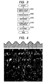
- Fig. 3 is a flow chart showing an embodiment of the method of manufacturing a solid electrolyte fuel cell according an embodiment of the invention. In this embodiment, an electrolyte-supported fuel cell is manufactured for example.
- step S101 ethanol, dibutyl phthalate and polyvinyl butyral are added to SDC (samaria-doped ceria) powder, and a green sheet is formed by a ball mill method.
- SDC sinaria-doped ceria
- step S102 the green sheet generated in step S101 is punched out, for example, to a square of 140 cm, and a fabric (such as a fabric material of organic fibers), which is a pattern mold for forming a roughened surface on the green sheet, is pressed onto both surfaces of the green sheet.
- a fabric such as a fabric material of organic fibers
- the assembly of the fabric, the green sheet and the fabric accumulated in this order is applied with a pressure, for example, of 150 kg/cm 2 at a room temperature for 5 minutes by holding with metallic flat plates from both sides of the assembly. According to the operation, the shape of the roughened surface of the fabric as the pattern mold is transferred to the green sheet.
- step S103 the green sheet having the roughened surface formed is punched out to a circular shape and sintered in the air, for example, at 1,300°C for 5 hours, so as to obtain an SDC disk.
- step S104 a NiO-SDC anode paste is coated on one surface of the SDC disk, and an SSC (Sm 0.5 Sr 0.5 CoO 3 )-SDC cathode paste is coated on the other surface thereof.
- Platinum meshes are embedded in the pastes.
- the platinum meshes are embedded in the electrodes for strengthening the electrodes and collecting electric power.
- Platinum wires are connected to the platinum meshes, respectively, for example, by welding, so as to provide electric connections to external circuits.
- step S105 the anode paste and the cathode paste are sintered in the air, for example, at 1,200°C for 1 hour.
- the solid oxide fuel cell including an SDC disk having a diameter of about 15 cm and electrodes formed thereon according the embodiment of the invention having been thus completed by the aforementioned procedures is subj ected to an electric power generation test by making a butane-air premixed flame in direct contact with the anode surface of the cell, and as a result, an electric power output density of about 140 mW/cm 2 is obtained.
- a related solid oxide fuel cell generated in the same procedures except that a roughened surface is formed by a sandpaper method is subjected to the same electric power generation test, and as a result, an electric power output density of about 100 mW/cm 2 is obtained. Accordingly, it has been experimentally confirmed that the solid oxide fuel cell of the invention is improved in electric power generation performance.
- the solid oxide fuel cell according to the embodiment of the invention may be applied in general types of fuel cells.
- the solid oxide fuel cell according to the embodiment of the invention is applied to a power generation system utilizing a combustion flame.
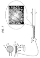
- Fig. 7 is a diagram showing the solid oxide fuel cell fueled with flames.
- a cathode 21 and an anode 22 both including the platinum meshes are formed on surfaces of a SDC disc 20 which is supported by platinum wires 27, a cathode 21 and an anode 22 both including the platinum meshes are formed.
- the anode 22 is exposed directly to a flame 24 which is emitted from a burner nozzle 25.
- This configuration is described in JP-A-2004-139936 and "Electrochemical Power Generation Directly from Combustion Flame of Gases, Liquids, and Solids", Michio Horiuchi, Shigeaki Suganuma, and Misa Watanabe, Journal of the Electrochemical Society, Vol.l5l, No.9, September 2004.
- an electrolyte 26 provided on the SDC disc 20 has the roughened surface formed with at least two different surface roughnesses as described above.
- an electrode mother body is produced with a green sheet and subjected to the aforementioned procedures.
- the pattern mold used for forming a roughened surface on a green sheet is a fiber fabric material or a metallic fabric material will be described below.
- Examples of the organic fiber material include acrylic fibers (polyacrylonitrile), cotton, silk, acetate fibers. Rayon, Tetron, polyester fibers, Vinylon, etc., and blended yarn thereof, etc.
- Examples of the inorganic fiber material include carbon, alumina, silica, boron, etc.
- Preferred examples of the metallic fiber material include SUS 304, 304L, 310S, 316, 316L, 321, 347, 410, 430, etc., and copper and nickel, etc., are also included.
- the pattern mold is a fabric material of organic fibers that even when an organic fabric material cannot be released from a green sheet after pressing the organic fabric material onto the green sheet to form the roughened surface, the organic fabric material can be burnt out in the subsequent sintering step.
- Examples of the texture of the fabric material include plain weave, twill weave, basket weave and sateen weave, and plain weave and twill weave are advantageous in cost.
- the pattern mold is formed of metallic fibers, it is advantageous in cost and repeated use, and examples of the texture thereof include plain weave, plain tatami mat weave, twill weave, twilled tatami mat weave, straw mat weave, crimped weave, lock crimped weave, flat-top weave, ton-cap weave, ty-rod weave, leno weave, rhombus weave, round weave, herringbone weave, wire conveyor net, hexagonal weave and the like.
- Fig. 4 is an enlarged view of a surface of a twill weave material for example. "Waviness" appeared on the fabric material functions as a roughness structure having a larger roughness frequency, and strands constituting the fabric function as a roughness structure having a smaller roughness frequency. The thin fibers constituting the strands function as a roughness structure having a further smaller roughness frequency.
- the pattern mold used for forming a roughened surface on a green sheet may be a metallic member having a surface shape transferred from the fabricmaterialwoven with inorganic fibers, organic fibers or thin metal wires.
- the surface shape of the fabric material is modeled with a metallic member in advance, and the metallic member is used as the pattern mold for forming a roughened surface on a green sheet.
- the pattern mold formed of a metallic member is advantageous since it can be repeatedly used.
- the intermediate particle diameter of the raw material powder of the solid electrolyte is preferably, for example, about from 0.5 to 10 ⁇ m.
- the fiber diameter is preferably about 0.5 ⁇ m or more while those having a diameter of about 0.1 ⁇ m are commercially available.
- the strand is preferably a twisted strand, and the diameter thereof is preferably about from 5 to 100 ⁇ m.
- a strand having a diameter of less than 5 ⁇ m is not preferred since it brings about increased cost and is poor in formation of a roughened surface.
- a strand having a diameter exceeding half of the thickness of the green sheet is not preferred. For example, a strand having a diameter exceeding 100 ⁇ m is not preferred for processing a green sheet having a thickness of about 200 ⁇ m.
- the pattern mold preferably has such a shape that forms an impression of strands or fibers over the entire surface where a roughened surface is to be formed.
- Fig. 5 is a micrograph showing a surface of a sintered body of a green sheet having been formed with a roughened surface according to the embodiment of the invention.
- Fig. 6 is an enlarged view of Fig. 5. It can be confirmed from the figures that on the roughness structure having a relatively large roughness frequency shown in Fig. 5, the roughness structures having a relatively smaller roughness frequency and a further smaller roughness frequency are formed as shown in Fig. 6. It is thus confirmed that such a roughened surface is formed in the embodiment that has plural surface roughnesses different from each other.
- the roughness structure having a larger roughness frequency shown in Fig. 5 corresponds to the waviness appeared on the fabricmaterial.
- the roughness structure having a smaller roughness frequency shown in Fig. 6 corresponds to the strands constituting the fabric, and the roughness structure having a further smaller roughness frequency shown in Fig. 6 corresponds to the thin fibers constituting the strands.
- the joint surface between the solid electrolyte and the electrode has a roughened surface having two or three surface roughnesses different from each other, i.e., a roughened surface having a roughness structure with two or three roughness frequencies different from each other, but a roughened surface having four or more surface roughnesses may be used in the invention.
- the invention can be applied to a solid oxide fuel cell including a solid electrolyte having electrodes on both surfaces thereof.
- the effective interface area between the solid electrolyte and the electrode can be further enlarged as compared to the related products, whereby the electric power generation performance of the solid oxide fuel cell can be improved.
- the enlargement of the effective interface area between the solid electrolyte and the electrode also improves the mechanical joint strength between the solid electrolyte and the electrode.
- the solid oxide fuel cell having an enlarged effective interface area can be produced at low cost.
Landscapes
- Chemical & Material Sciences (AREA)
- Engineering & Computer Science (AREA)
- Chemical Kinetics & Catalysis (AREA)
- Electrochemistry (AREA)
- General Chemical & Material Sciences (AREA)
- Manufacturing & Machinery (AREA)
- Life Sciences & Earth Sciences (AREA)
- Sustainable Development (AREA)
- Sustainable Energy (AREA)
- Thermal Sciences (AREA)
- Physics & Mathematics (AREA)
- Ceramic Engineering (AREA)
- Fuel Cell (AREA)
- Inert Electrodes (AREA)
Abstract
A solid oxide fuel cell (1) includes: a solid electrolyte (11); and electrodes (12,13) on both surfaces of the solid electrolyte, wherein at least one of joint surfaces where the solid electrolyte and the electrodes are in contact with each other is a roughened surface having at least two different types of surface roughness.
Description
- The present invention relates to a solid oxide fuel cell and a method of manufacturing the same.
- A solid oxide fuel cell undergoes an electrode reaction at a three-phase interface of a solid electrolyte, an electrode and a gas phase. In order to improve electric power generation performance of a fuel cell, therefore, it is necessary that the area of the interface between the solid electrolyte and the electrode, i.e., a joint surface, (which is sometimes referred to as an effective interface area) is enlarged as much as possible so as to reduce the interface resistance, whereby the electrode reaction is accelerated. The enlargement of the effective interface area between the solid electrolyte and the electrode also improves the mechanical joint strength between the solid electrolyte and the electrode.
- In order to enlarge the effective interface area between the solid electrolyte and the electrode, such a method has been practiced that a surface of an electrolyte is roughened so as to form roughness on the surface (as described, for example, in
JP-A-7-073890 - For example, such a method has been proposed that particles are applied and attached to a surface of amother body and sintered simultaneously with the mother body so as to form a large number of convex portions on the surface of the mother body, and then an electrode is attached to the surface having the convex portions formed thereon (as described, for example, in
JP-A-62-045596 JP-A-56-160653 - Such a method has been also proposed that a roughened surface is formed by making coarse particles present only on a part of an electrode, which is in contact with a solid electrolyte, but not present on the other parts thereof, by a slurry method or a thermal spraying method (as described, for example, in
Japanese Patent No. 2,695,641 - In all the related method for forming a roughened surface, a roughened surface cannot be obtained effectively with respect to the complicated operation or high cost of the methods. Fig. 8 is a schematic cross sectional view showing a roughened surface of a solid electrolyte formed by the related methods for forming a roughened surface. Although a roughened surface can be formed on a
solid electrolyte 51, for example, by a sandblastingmethod, repetition frequency of roughness on the roughened surface (which is sometimes referred to as a roughness frequency) is almost constant as shown in the figure. There is limitation in enlargement of the effective interface area by the related methods for forming a roughened surface, and therefore, improvement in electric power generation performance of a fuel cell is also limited. - The present invention has been made in view of the above circumstances, and provides a solid electrolyte fuel cell in which an area of a joint surface between a solid electrolyte and an electrode is further enlarged so as to improve electric power generation performance thereof, and a method of manufacturing the solid electrolyte fuel cell.
- According to a first aspect of the present invention, there is provided a solid oxide fuel cell comprising:
- a solid electrolyte; and
- electrodes on both surfaces of the solid electrolyte,
- wherein at least one of joint surfaces where the solid electrolyte and the electrodes are in contact with each other is a roughened surface having at least two different types of surface roughness.
- In the solid oxide fuel cell, the roughened surface may include:
- a first roughened surface having a first type of the surface roughness; and
- a second roughened surface having a second type of the surface roughness being formed on the first roughened surface.
- In the solid oxide fuel cell, the second type of the surface roughness may be finer in roughness than the first type of the surface roughness.
- In the solid oxide fuel cell, at least one of the solid electrolyte and the electrodes may be generated by sintering a green sheet which is used in a green sheet sintering process and on which a pattern of the roughened surface is formed by being pressed with a pattern mold.
- The effective interface area of the joint surface between the solid electrolyte and the electrode in a solid oxide fuel cell may be further enlarged so as to improve the electric power generation performance of the solid oxide fuel cell. The enlargement of the effective interface area between the solid electrolyte and the electrode also improves the mechanical joint strength between the solid electrolyte and the electrode. Such a solid oxide fuel cell that has an enlarged effective interface area can be produced at low cost.
- According to a second aspect of the present invention, there is provided a method of manufacturing a solid oxide fuel cell including a solid electrolyte having electrodes on both surfaces thereof, the method comprising:
- forming at least one of joint surfaces where the solid electrolyte and the electrodes are in contact with each other to be a roughened surface having at least two different types of surface roughness.
-
- Fig. I is a schematic cross sectional view showing a solid oxide fuel cell according to an embodiment of the invention.
- Fig. 2 is a schematic enlarged cross sectional view showing a roughened surface of the solid electrolyte of the solid oxide fuel cell shown in Fig. 1.
- Fig. 3 is a flow chart showing an embodiment of the method for manufacturing a solid electrolyte fuel cell according an embodiment of the invention.
- Fig. 4 is an enlarged view of a surface of a twill weave material.
- Fig. 5 is a micrograph showing a surface of a sintered body of a green sheet having been formed with a roughened surface according to the embodiment of the invention.
- Fig. 6 is an enlarged view of Fig. 5.
- Fig. 7 is a diagram showing a solid oxide fuel cell fueled with flames.
- Fig. 8 is a schematic cross sectional view showing a roughened surface of a solid electrolyte formed by the related methods for forming a roughened surface.
- Fig. 1 is a schematic cross sectional view showing a solid oxide fuel cell according to an embodiment of the invention. Fig. 2 is a schematic enlarged cross sectional view showing the roughened surface of the solid electrolyte of the solid oxide fuel cell shown in Fig. 1.
- According to the embodiment of the invention, in a solid
oxide fuel cell 1 including asolid electrolyte 11 havingelectrodes solid electrolyte 11 and theelectrodes solid electrolyte 11. - As the roughened surfaces having at least two surface roughnesses different from each other on the joint surfaces between the
solid electrolyte 11 and theelectrodes solid electrolyte 11 and theelectrodes - The
solid electrolyte 11 in the embodiment is generated with a green sheet used in the green sheet sintering method by sintering the green sheet having the roughened surface formed by pressing a pattern mold thereon. - The pattern mold has a roughened surface being a mold of the roughened surface to be formed on the green sheet. The roughened surface on the pattern mold has a roughened surface having a first surface roughness, on which a roughened surface having a second surface roughness is formed, and the second surface roughness is finer than the first surface roughness. In other words, the pattern mold has a roughness structure having at least two roughness frequencies different from each other corresponding to the roughness structure to be formed on the green sheet, and the roughness structure on the pattern mold has a first roughness structure having a relatively large roughness frequency and a second roughness structure having a relatively small roughness frequency formed on the first roughness structure. The pattern mold having a roughened surface having the first surface roughness, on which a roughened surface having the second surface roughness is formed, is formed of a fabric material woven with inorganic fibers, organic fibers or thin metal wires, or a metallic member having a surface shape transferred from a fabric material woven with inorganic fibers, organic fibers or thin metal wires.
- The method of manufacturing a solid oxide fuel cell according to an embodiment of the invention roughly includes two process steps: a transferring step of transferring a roughened surface of a pattern mold onto at least one surface of a green sheet used in a green sheet sintering method by pressing the pattern mold onto the surface of the green sheet; and a sintering step of sintering the green sheet having the roughened surface formed in the preceding transferring step to form the solid electrolyte or the electrode. A specific example of the methodwill be described in detail. Fig. 3 is a flow chart showing an embodiment of the method of manufacturing a solid electrolyte fuel cell according an embodiment of the invention. In this embodiment, an electrolyte-supported fuel cell is manufactured for example.
- In step S101, ethanol, dibutyl phthalate and polyvinyl butyral are added to SDC (samaria-doped ceria) powder, and a green sheet is formed by a ball mill method.
- In step S102, the green sheet generated in step S101 is punched out, for example, to a square of 140 cm, and a fabric (such as a fabric material of organic fibers), which is a pattern mold for forming a roughened surface on the green sheet, is pressed onto both surfaces of the green sheet. The assembly of the fabric, the green sheet and the fabric accumulated in this order is applied with a pressure, for example, of 150 kg/cm2 at a room temperature for 5 minutes by holding with metallic flat plates from both sides of the assembly. According to the operation, the shape of the roughened surface of the fabric as the pattern mold is transferred to the green sheet.
- In step S103, the green sheet having the roughened surface formed is punched out to a circular shape and sintered in the air, for example, at 1,300°C for 5 hours, so as to obtain an SDC disk.
- In step S104, a NiO-SDC anode paste is coated on one surface of the SDC disk, and an SSC (Sm0.5Sr0.5CoO3)-SDC cathode paste is coated on the other surface thereof. Platinum meshes are embedded in the pastes. The platinum meshes are embedded in the electrodes for strengthening the electrodes and collecting electric power. Platinum wires are connected to the platinum meshes, respectively, for example, by welding, so as to provide electric connections to external circuits.
- In step S105, the anode paste and the cathode paste are sintered in the air, for example, at 1,200°C for 1 hour.
- The solid oxide fuel cell including an SDC disk having a diameter of about 15 cm and electrodes formed thereon according the embodiment of the invention having been thus completed by the aforementioned procedures is subj ected to an electric power generation test by making a butane-air premixed flame in direct contact with the anode surface of the cell, and as a result, an electric power output density of about 140 mW/cm2 is obtained. For comparison, a related solid oxide fuel cell generated in the same procedures except that a roughened surface is formed by a sandpaper method is subjected to the same electric power generation test, and as a result, an electric power output density of about 100 mW/cm2 is obtained. Accordingly, it has been experimentally confirmed that the solid oxide fuel cell of the invention is improved in electric power generation performance.
- The solid oxide fuel cell according to the embodiment of the invention may be applied in general types of fuel cells. For example, in the above electric power generation test, the solid oxide fuel cell according to the embodiment of the invention is applied to a power generation system utilizing a combustion flame.
- Fig. 7 is a diagram showing the solid oxide fuel cell fueled with flames. On surfaces of a
SDC disc 20 which is supported byplatinum wires 27, acathode 21 and ananode 22 both including the platinum meshes are formed. Theanode 22 is exposed directly to aflame 24 which is emitted from aburner nozzle 25. This configuration is described inJP-A-2004-139936 electrolyte 26 provided on theSDC disc 20 has the roughened surface formed with at least two different surface roughnesses as described above. - In the case where the method of the embodiment of the invention is applied to manufacturing of an electrode-supported fuel cell, an electrode mother body is produced with a green sheet and subjected to the aforementioned procedures.
- Specific examples of the cases where the pattern mold used for forming a roughened surface on a green sheet is a fiber fabric material or a metallic fabric material will be described below.
- Examples of the organic fiber material include acrylic fibers (polyacrylonitrile), cotton, silk, acetate fibers. Rayon, Tetron, polyester fibers, Vinylon, etc., and blended yarn thereof, etc. Examples of the inorganic fiber material include carbon, alumina, silica, boron, etc. Preferred examples of the metallic fiber material include SUS 304, 304L, 310S, 316, 316L, 321, 347, 410, 430, etc., and copper and nickel, etc., are also included. There is such an advantage in the case where the pattern mold is a fabric material of organic fibers that even when an organic fabric material cannot be released from a green sheet after pressing the organic fabric material onto the green sheet to form the roughened surface, the organic fabric material can be burnt out in the subsequent sintering step.
- Examples of the texture of the fabric material include plain weave, twill weave, basket weave and sateen weave, and plain weave and twill weave are advantageous in cost. In the case where the pattern mold is formed of metallic fibers, it is advantageous in cost and repeated use, and examples of the texture thereof include plain weave, plain tatami mat weave, twill weave, twilled tatami mat weave, straw mat weave, crimped weave, lock crimped weave, flat-top weave, ton-cap weave, ty-rod weave, leno weave, rhombus weave, round weave, herringbone weave, wire conveyor net, hexagonal weave and the like. In consideration of cost and formation of fine roughness, plane tatami mat weave, twill weave and twilled tatami mat weave are preferred. Fig. 4 is an enlarged view of a surface of a twill weave material for example. "Waviness" appeared on the fabric material functions as a roughness structure having a larger roughness frequency, and strands constituting the fabric function as a roughness structure having a smaller roughness frequency. The thin fibers constituting the strands function as a roughness structure having a further smaller roughness frequency.
- The pattern mold used for forming a roughened surface on a green sheet may be a metallic member having a surface shape transferred from the fabricmaterialwoven with inorganic fibers, organic fibers or thin metal wires. In other words, the surface shape of the fabric material is modeled with a metallic member in advance, and the metallic member is used as the pattern mold for forming a roughened surface on a green sheet. The pattern mold formed of a metallic member is advantageous since it can be repeatedly used.
- One example of the relationshipbetween the weaving density of the fabric material as the pattern mold for forming a roughened surface on a green sheet and the raw material powder of the green sheet for forming the solid electrolyte is shown below.
- The intermediate particle diameter of the raw material powder of the solid electrolyte is preferably, for example, about from 0.5 to 10 µm. The fiber diameter is preferably about 0.5 µm or more while those having a diameter of about 0.1 µm are commercially available. The strand is preferably a twisted strand, and the diameter thereof is preferably about from 5 to 100 µm. A strand having a diameter of less than 5 µm is not preferred since it brings about increased cost and is poor in formation of a roughened surface. A strand having a diameter exceeding half of the thickness of the green sheet is not preferred. For example, a strand having a diameter exceeding 100 µm is not preferred for processing a green sheet having a thickness of about 200 µm. Ahigher weaving density with in the aforementioned range is preferred for forming a roughened surface having fine roughness, and it is practically preferred that the designed values are determined in consideration of balance between cost and effect. In general, the pattern mold preferably has such a shape that forms an impression of strands or fibers over the entire surface where a roughened surface is to be formed.
- Fig. 5 is a micrograph showing a surface of a sintered body of a green sheet having been formed with a roughened surface according to the embodiment of the invention. Fig. 6 is an enlarged view of Fig. 5. It can be confirmed from the figures that on the roughness structure having a relatively large roughness frequency shown in Fig. 5, the roughness structures having a relatively smaller roughness frequency and a further smaller roughness frequency are formed as shown in Fig. 6. It is thus confirmed that such a roughened surface is formed in the embodiment that has plural surface roughnesses different from each other. The roughness structure having a larger roughness frequency shown in Fig. 5 corresponds to the waviness appeared on the fabricmaterial. The roughness structure having a smaller roughness frequency shown in Fig. 6 corresponds to the strands constituting the fabric, and the roughness structure having a further smaller roughness frequency shown in Fig. 6 corresponds to the thin fibers constituting the strands.
- In the aforementioned embodiment, the joint surface between the solid electrolyte and the electrode has a roughened surface having two or three surface roughnesses different from each other, i.e., a roughened surface having a roughness structure with two or three roughness frequencies different from each other, but a roughened surface having four or more surface roughnesses may be used in the invention.
- The invention can be applied to a solid oxide fuel cell including a solid electrolyte having electrodes on both surfaces thereof. According to the invention, the effective interface area between the solid electrolyte and the electrode can be further enlarged as compared to the related products, whereby the electric power generation performance of the solid oxide fuel cell can be improved. The enlargement of the effective interface area between the solid electrolyte and the electrode also improves the mechanical joint strength between the solid electrolyte and the electrode. According to the invention, furthermore, the solid oxide fuel cell having an enlarged effective interface area can be produced at low cost.
- It will be apparent to those skilled in the art that various modifications and variations can be made to the described preferred embodiments of the present invention without departing from the spirit or scope of the invention. Thus, it is intended that the present invention cover all modifications and variations of this invention consistent with the scope of the appended claims and their equivalents.
Claims (18)
- A solid oxide fuel cell comprising:a solid electrolyte; andelectrodes on both surfaces of the solid electrolyte,wherein at least one of joint surfaces where the solid electrolyte and the electrodes are in contact with each other is a roughened surface having at least two different types of surface roughness.
- The solidoxide fuel cell as claimed in claim 1, wherein the roughened surface includes:a first roughened surface having a first type of the surface roughness; anda second roughened surface having a second type of the surface roughness being formed on the first roughened surface.
- The solid oxide fuel cell as claimed in claim 2, wherein the second type of the surface roughness is finer in roughness than the first type of the surface roughness.
- The solid oxide fuel cell as claimed in claim 1, wherein at least one of the solid electrolyte and the electrodes is generated by sintering a green sheet which is used in a green sheet sintering process and on which a pattern of the roughened surface is formed by being pressed with a pattern mold.
- The solid oxide fuel cell as claimed in claim 4, wherein the pattern mold has a pattern mold roughened surface to be a mold of the pattern of the roughened surface that is to be formed on the green sheet.
- The solid oxide fuel cell as claimed in claim 5, wherein the pattern mold roughened surface includes:a first roughened surface having a first type of the surface roughness; anda second roughened surface having a second type of the surface roughness being formed on the first roughened surface.
- The solid oxide fuel cell as claimed in claim 6, wherein the second type of the surface roughness is finer in roughness than the first type of the surface roughness.
- The solid oxide fuel cell as claimed in claim 4, wherein the pattern mold includes a fabric material that is woven with inorganic fibers, organic fibers or thin metal wires.
- The solid oxide fuel cell as claimed in claim 4, wherein the pattern mold includes a metallic member on which a surface shape of a fabric material that is woven with inorganic fibers, organic fibers or thin metal wires is transferred.
- A method of manufacturing a solid oxide fuel cell including a solid electrolyte having electrodes on both surfaces thereof, the method comprising:forming at least one of joint surfaces where the solid electrolyte and the electrodes are in contact with each other to be a roughened surface having at least two different types of surface roughness.
- The method of manufacturing the solid oxide fuel as claimed in claim 10, wherein the roughened surface includes:a first roughened surface having a first type of the surface roughness; anda second roughened surface having a second type of the surface roughness being formed on the first roughened surface.
- The method of manufacturing the solid oxide fuel as claimed in claim 11, wherein the second type of the surface roughness is finer in roughness than the first type of the surface roughness.
- The method of manufacturing the solid oxide fuel as claimed in claim 10, comprising:forming a pattern of the roughened surface on a green sheet which is used in a green sheet sintering process by pressing a pattern mold on at least one surface of the green sheet; andgenerating at least one of the solid electrolyte and the electrodes by sintering the green sheet on which the pattern of the roughened surface is formed.
- The method of manufacturing the solid oxide fuel as claimed in claim 13, wherein the pattern mold has a pattern mold roughened surface to be a mold of the pattern of the roughened surface that is to be formed on the green sheet.
- The method of manufacturing the solid oxide fuel as claimed in claim 14, wherein the pattern mold roughened surface includes:a first roughened surface having a first type of the surface roughness; anda second roughened surface having a second type of the surface roughness being formed on the first roughened surface.
- The method of manufacturing the solid oxide fuel as claimed in claim 15, wherein the second type of the surface roughness is finer in roughness than the first type of the surface roughness.
- The method of manufacturing the solid oxide fuel as claimed in claim 13, wherein the pattern mold includes a fabric material that is woven with inorganic fibers, organic fibers or thin metal wires.
- The method of manufacturing the solid oxide fuel as claimed in claim 13, wherein the pattern mold includes a metallic member on which a surface shape of a fabric material that is woven with inorganic fibers, organic fibers or thin metal wires is transferred.
Applications Claiming Priority (1)
| Application Number | Priority Date | Filing Date | Title |
|---|---|---|---|
| JP2005148056A JP2006324190A (en) | 2005-05-20 | 2005-05-20 | Solid oxide fuel cell and method for producing the same |
Publications (1)
| Publication Number | Publication Date |
|---|---|
| EP1724870A1 true EP1724870A1 (en) | 2006-11-22 |
Family
ID=36608707
Family Applications (1)
| Application Number | Title | Priority Date | Filing Date |
|---|---|---|---|
| EP06252613A Withdrawn EP1724870A1 (en) | 2005-05-20 | 2006-05-19 | Solid oxide fuel cell and method of manufacturing the same |
Country Status (5)
| Country | Link |
|---|---|
| US (1) | US8057950B2 (en) |
| EP (1) | EP1724870A1 (en) |
| JP (1) | JP2006324190A (en) |
| CN (1) | CN1866598A (en) |
| CA (1) | CA2547288A1 (en) |
Cited By (1)
| Publication number | Priority date | Publication date | Assignee | Title |
|---|---|---|---|---|
| EP2413408A4 (en) * | 2009-03-25 | 2015-06-03 | Nippon Catalytic Chem Ind | ELECTROLYTE SHEET FOR SOLID OXIDE CELL, PROCESS FOR PRODUCTION THEREOF, AND CELL FOR SOLID OXIDE CELL |
Families Citing this family (12)
| Publication number | Priority date | Publication date | Assignee | Title |
|---|---|---|---|---|
| JP4861735B2 (en) * | 2006-03-30 | 2012-01-25 | 新光電気工業株式会社 | Solid electrolyte fuel cell and manufacturing method thereof |
| FR2946463B1 (en) * | 2009-06-04 | 2011-10-28 | Commissariat Energie Atomique | ELECTROLYTE SUPPORT FOR ELECTROCHEMICAL SYSTEM |
| JP2011046127A (en) * | 2009-08-27 | 2011-03-10 | Nippon Shokubai Co Ltd | Method for manufacturing surface-roughened ceramic green sheet |
| US10431841B2 (en) * | 2014-11-18 | 2019-10-01 | Lg Chem, Ltd. | Method for manufacturing solid oxide fuel cell |
| JP2017174516A (en) * | 2016-03-18 | 2017-09-28 | 大阪瓦斯株式会社 | Electrochemical element, electrochemical module, electrochemical device, energy system, solid oxide fuel cell, and method of manufacturing electrochemical element |
| JP6814594B2 (en) * | 2016-10-18 | 2021-01-20 | 株式会社日本触媒 | Electrolyte sheet for solid oxide fuel cell |
| WO2021025051A1 (en) * | 2019-08-06 | 2021-02-11 | 株式会社村田製作所 | Electrolyte sheet for solid oxide fuel battery, production method of electrolyte sheet for solid oxide fuel battery, and single cell for solid oxide fuel battery |
| CN118451576A (en) * | 2021-12-27 | 2024-08-06 | 株式会社村田制作所 | Electrolyte sheet for solid oxide fuel cell and single cell for solid oxide fuel cell |
| JP7604715B2 (en) * | 2022-03-08 | 2024-12-23 | 日本碍子株式会社 | Electrochemical Cell |
| KR20240081211A (en) * | 2022-11-30 | 2024-06-07 | 롯데케미칼 주식회사 | Lithium secondary battery |
| CN121416562A (en) * | 2025-12-24 | 2026-01-27 | 哈尔滨工业大学(深圳)(哈尔滨工业大学深圳科技创新研究院) | An interface optimization method for solid oxide fuel cells and the cell itself. |
| CN121439714A (en) * | 2025-12-26 | 2026-01-30 | 中国第一汽车股份有限公司 | Method and apparatus for fabricating composite electrode structures for all-solid-state batteries |
Citations (6)
| Publication number | Priority date | Publication date | Assignee | Title |
|---|---|---|---|---|
| JPH0395864A (en) * | 1989-09-08 | 1991-04-22 | Fujikura Ltd | Manufacture of solid electrolyte fuel cell |
| JPH03134963A (en) * | 1989-10-19 | 1991-06-07 | Fuji Electric Co Ltd | Solid electrolyte type fuel cell |
| JPH03147268A (en) * | 1989-10-31 | 1991-06-24 | Sanyo Electric Co Ltd | Solid electrolyte fuel cell |
| JPH04190564A (en) * | 1990-11-22 | 1992-07-08 | Tokyo Gas Co Ltd | Manufacture of solid electrolyte fuel cell |
| EP0615299A1 (en) * | 1993-03-10 | 1994-09-14 | Murata Manufacturing Co., Ltd. | Solid oxide fuel cell and manufacturing method thereof |
| WO1994025994A1 (en) * | 1993-04-30 | 1994-11-10 | Siemens Aktiengesellschaft | High-temperature fuel cell with improved solid electrolyte/electrode contact surface, and method of producing the contact surface |
Family Cites Families (9)
| Publication number | Priority date | Publication date | Assignee | Title |
|---|---|---|---|---|
| US4135040A (en) | 1977-12-20 | 1979-01-16 | General Electric Company | Solid ion-conductive electrolyte body and method of forming |
| JPS56160653A (en) | 1980-05-14 | 1981-12-10 | Ngk Spark Plug Co Ltd | Manufacture of oxygen concentration cell |
| JPS59114755A (en) * | 1982-12-22 | 1984-07-02 | Oji Paper Co Ltd | Sack-like separator for storage battery |
| JPS6245496A (en) | 1985-08-23 | 1987-02-27 | Nec Corp | Reflection type mask for laser |
| JP2695641B2 (en) | 1988-03-04 | 1998-01-14 | 三菱重工業株式会社 | Method for manufacturing solid electrolyte fuel cell |
| JPH09223506A (en) * | 1996-02-14 | 1997-08-26 | Murata Mfg Co Ltd | Manufacture of solid electrolyte fuel cell |
| JPH09320616A (en) * | 1996-05-23 | 1997-12-12 | Unyusho Senpaku Gijutsu Kenkyusho | High output type solid oxide fuel cell having roughened interface between electrolytic film and electrode closely attached to the electrolytic film |
| JP4104418B2 (en) | 2002-10-21 | 2008-06-18 | 新光電気工業株式会社 | Fuel cell |
| US7531261B2 (en) * | 2003-06-30 | 2009-05-12 | Corning Incorporated | Textured electrolyte sheet for solid oxide fuel cell |
-
2005
- 2005-05-20 JP JP2005148056A patent/JP2006324190A/en active Pending
-
2006
- 2006-05-19 US US11/419,376 patent/US8057950B2/en not_active Expired - Fee Related
- 2006-05-19 CN CNA2006100805881A patent/CN1866598A/en active Pending
- 2006-05-19 EP EP06252613A patent/EP1724870A1/en not_active Withdrawn
- 2006-05-19 CA CA002547288A patent/CA2547288A1/en not_active Abandoned
Patent Citations (6)
| Publication number | Priority date | Publication date | Assignee | Title |
|---|---|---|---|---|
| JPH0395864A (en) * | 1989-09-08 | 1991-04-22 | Fujikura Ltd | Manufacture of solid electrolyte fuel cell |
| JPH03134963A (en) * | 1989-10-19 | 1991-06-07 | Fuji Electric Co Ltd | Solid electrolyte type fuel cell |
| JPH03147268A (en) * | 1989-10-31 | 1991-06-24 | Sanyo Electric Co Ltd | Solid electrolyte fuel cell |
| JPH04190564A (en) * | 1990-11-22 | 1992-07-08 | Tokyo Gas Co Ltd | Manufacture of solid electrolyte fuel cell |
| EP0615299A1 (en) * | 1993-03-10 | 1994-09-14 | Murata Manufacturing Co., Ltd. | Solid oxide fuel cell and manufacturing method thereof |
| WO1994025994A1 (en) * | 1993-04-30 | 1994-11-10 | Siemens Aktiengesellschaft | High-temperature fuel cell with improved solid electrolyte/electrode contact surface, and method of producing the contact surface |
Non-Patent Citations (4)
| Title |
|---|
| PATENT ABSTRACTS OF JAPAN vol. 015, no. 277 (E - 1089) 15 July 1991 (1991-07-15) * |
| PATENT ABSTRACTS OF JAPAN vol. 015, no. 348 (E - 1107) 4 September 1991 (1991-09-04) * |
| PATENT ABSTRACTS OF JAPAN vol. 015, no. 371 (E - 1113) 18 September 1991 (1991-09-18) * |
| PATENT ABSTRACTS OF JAPAN vol. 016, no. 513 (E - 1283) 22 October 1992 (1992-10-22) * |
Cited By (1)
| Publication number | Priority date | Publication date | Assignee | Title |
|---|---|---|---|---|
| EP2413408A4 (en) * | 2009-03-25 | 2015-06-03 | Nippon Catalytic Chem Ind | ELECTROLYTE SHEET FOR SOLID OXIDE CELL, PROCESS FOR PRODUCTION THEREOF, AND CELL FOR SOLID OXIDE CELL |
Also Published As
| Publication number | Publication date |
|---|---|
| US20070026289A1 (en) | 2007-02-01 |
| JP2006324190A (en) | 2006-11-30 |
| US8057950B2 (en) | 2011-11-15 |
| CA2547288A1 (en) | 2006-11-20 |
| CN1866598A (en) | 2006-11-22 |
Similar Documents
| Publication | Publication Date | Title |
|---|---|---|
| US8057950B2 (en) | Solid oxide fuel cell and method of manufacturing the same | |
| JP5224649B2 (en) | Conductive connecting member and solid oxide fuel cell | |
| CA2647414C (en) | A sofc stack having a high temperature bonded ceramic interconnect and method for making same | |
| CN106575784B (en) | Membrane electrode assembly and its manufacturing method, fuel cell and its manufacturing method | |
| JP6658754B2 (en) | Solid oxide fuel cell and method for producing electrolyte layer-anode assembly | |
| JP5631625B2 (en) | Solid oxide fuel cell | |
| JP3323038B2 (en) | Solid oxide fuel cell | |
| CN113258112A (en) | Preparation method of metal-supported solid oxide fuel cell and fuel cell | |
| CN113258113B (en) | Metal-supported solid oxide fuel cell and preparation method thereof | |
| JP7248030B2 (en) | Fuel cell | |
| JP7696223B2 (en) | Electrochemical cell and method for producing the same | |
| JP7243728B2 (en) | Chromium adsorption materials and fuel cells | |
| CN116169334A (en) | Metal supported SOFC and its preparation method and fuel cell | |
| JP2005166422A (en) | Solid oxide fuel cell, cell plate and method for producing the same | |
| JP6965041B2 (en) | Electrochemical reaction single cell and electrochemical reaction cell stack | |
| JP4342267B2 (en) | Solid oxide fuel cell and method for producing the same | |
| JP3592839B2 (en) | Method for producing electrolyte plate, ceramic reinforcing material and ceramic sintered body | |
| KR101328336B1 (en) | Cathode current collector for solid oxide fuel cell, method for manufacturing the same and solid oxide fuel cell comprising the same | |
| JP2020128324A (en) | Ceramic green sheet, method for producing ceramic sintered body, and method for producing electrochemical reaction single cell | |
| WO2024148419A1 (en) | Titanium textile | |
| WO2025115808A1 (en) | Electrochemical cell and method for manufacturing same | |
| JP2025089102A (en) | Porous metal plate and its manufacturing method | |
| JPH09115535A (en) | Porous collector for solid electrolyte fuel cell |
Legal Events
| Date | Code | Title | Description |
|---|---|---|---|
| PUAI | Public reference made under article 153(3) epc to a published international application that has entered the european phase |
Free format text: ORIGINAL CODE: 0009012 |
|
| AK | Designated contracting states |
Kind code of ref document: A1 Designated state(s): AT BE BG CH CY CZ DE DK EE ES FI FR GB GR HU IE IS IT LI LT LU LV MC NL PL PT RO SE SI SK TR |
|
| AX | Request for extension of the european patent |
Extension state: AL BA HR MK YU |
|
| 17P | Request for examination filed |
Effective date: 20070509 |
|
| AKX | Designation fees paid |
Designated state(s): DE GB |
|
| STAA | Information on the status of an ep patent application or granted ep patent |
Free format text: STATUS: THE APPLICATION HAS BEEN WITHDRAWN |
|
| 18W | Application withdrawn |
Effective date: 20110121 |