EP1724499A2 - Drive unit - Google Patents
Drive unit Download PDFInfo
- Publication number
- EP1724499A2 EP1724499A2 EP06009838A EP06009838A EP1724499A2 EP 1724499 A2 EP1724499 A2 EP 1724499A2 EP 06009838 A EP06009838 A EP 06009838A EP 06009838 A EP06009838 A EP 06009838A EP 1724499 A2 EP1724499 A2 EP 1724499A2
- Authority
- EP
- European Patent Office
- Prior art keywords
- hydraulic
- hydraulic motor
- drive device
- clutch
- motor
- Prior art date
- Legal status (The legal status is an assumption and is not a legal conclusion. Google has not performed a legal analysis and makes no representation as to the accuracy of the status listed.)
- Granted
Links
- 230000008878 coupling Effects 0.000 claims description 22
- 238000010168 coupling process Methods 0.000 claims description 22
- 238000005859 coupling reaction Methods 0.000 claims description 22
- 238000006073 displacement reaction Methods 0.000 claims description 12
- 238000010276 construction Methods 0.000 claims description 4
- 238000001514 detection method Methods 0.000 claims description 4
- 230000005540 biological transmission Effects 0.000 description 2
- 230000001133 acceleration Effects 0.000 description 1
- 230000000903 blocking effect Effects 0.000 description 1
- 230000000295 complement effect Effects 0.000 description 1
- 230000007423 decrease Effects 0.000 description 1
- 230000001419 dependent effect Effects 0.000 description 1
- 239000012530 fluid Substances 0.000 description 1
- 238000000034 method Methods 0.000 description 1
- 238000000926 separation method Methods 0.000 description 1
- 230000001360 synchronised effect Effects 0.000 description 1
Images


Classifications
-
- F—MECHANICAL ENGINEERING; LIGHTING; HEATING; WEAPONS; BLASTING
- F16—ENGINEERING ELEMENTS AND UNITS; GENERAL MEASURES FOR PRODUCING AND MAINTAINING EFFECTIVE FUNCTIONING OF MACHINES OR INSTALLATIONS; THERMAL INSULATION IN GENERAL
- F16H—GEARING
- F16H61/00—Control functions within control units of change-speed- or reversing-gearings for conveying rotary motion ; Control of exclusively fluid gearing, friction gearing, gearings with endless flexible members or other particular types of gearing
- F16H61/38—Control of exclusively fluid gearing
- F16H61/40—Control of exclusively fluid gearing hydrostatic
- F16H61/44—Control of exclusively fluid gearing hydrostatic with more than one pump or motor in operation
- F16H61/452—Selectively controlling multiple pumps or motors, e.g. switching between series or parallel
-
- F—MECHANICAL ENGINEERING; LIGHTING; HEATING; WEAPONS; BLASTING
- F16—ENGINEERING ELEMENTS AND UNITS; GENERAL MEASURES FOR PRODUCING AND MAINTAINING EFFECTIVE FUNCTIONING OF MACHINES OR INSTALLATIONS; THERMAL INSULATION IN GENERAL
- F16D—COUPLINGS FOR TRANSMITTING ROTATION; CLUTCHES; BRAKES
- F16D23/00—Details of mechanically-actuated clutches not specific for one distinct type
- F16D23/02—Arrangements for synchronisation, also for power-operated clutches
- F16D23/04—Arrangements for synchronisation, also for power-operated clutches with an additional friction clutch
-
- F—MECHANICAL ENGINEERING; LIGHTING; HEATING; WEAPONS; BLASTING
- F16—ENGINEERING ELEMENTS AND UNITS; GENERAL MEASURES FOR PRODUCING AND MAINTAINING EFFECTIVE FUNCTIONING OF MACHINES OR INSTALLATIONS; THERMAL INSULATION IN GENERAL
- F16H—GEARING
- F16H61/00—Control functions within control units of change-speed- or reversing-gearings for conveying rotary motion ; Control of exclusively fluid gearing, friction gearing, gearings with endless flexible members or other particular types of gearing
- F16H61/38—Control of exclusively fluid gearing
- F16H61/40—Control of exclusively fluid gearing hydrostatic
- F16H61/44—Control of exclusively fluid gearing hydrostatic with more than one pump or motor in operation
- F16H61/448—Control circuits for tandem pumps or motors
Definitions
- the present invention relates to a drive device for a vehicle and / or a construction machine, comprising a hydraulic motor unit, which has two hydraulic motors connected in series, whose motor shafts can be connected to one another in a rotationally fixed manner by a clutch.
- Such drive means with a hydraulic motor unit are regularly used in construction machinery and can be installed as a single-wheel drive or drive the drive pinion of a transmission, a drive axle or the shaft of a linear actuator with its motor shaft.
- By the two series-connected hydraulic motors high torques can be generated especially when starting. After overcoming the starting resistance, however, such high torque is no longer necessary at higher speeds.
- a drive device with a hydraulic motor unit of the aforementioned type shows, for example, the DE 42 28 294 B4 , which proposes to connect two hydraulic motors in series and to couple with their motor shafts rotatably, so on protruding on both sides of the motor housing, a motor shaft drive portion which is coupled to the drive axle of a four-wheel drive vehicle. It is provided that the swash plates designed as axial piston motors hydraulic motors can be adjusted separately for each motor, whereby the torques of the two hydraulic motors complement each other and the torque of the entire hydraulic motor unit can be controlled in total. Even with this known drive device, however, it would be desirable to be able to reduce the losses during operation at higher speeds and lower required torques and thus to enable more efficient operation.
- the present invention is based on the object to provide an improved drive device of the type mentioned above, which avoids the disadvantages of the prior art and further develops the latter in an advantageous manner.
- the drive device is to be improved so that at higher speeds, the drive device generates lower losses.
- the coupling is detachably designed and can also be engaged and disengaged by an actuating device during operation of the hydraulic motor unit.
- At least one of the hydraulic motors is hydraulically switched off independently of the operation of the other hydraulic motor, so that in particular at higher speeds, the drive device can drive with only one hydraulic motor. Since the other hydraulic motor can be mechanically disengaged and switched off, its drag losses can be completely eliminated and thus minimized overall.
- the engageable and disengageable Training the connection of the two hydraulic motors in operation with the engine running and torque generation at any time the switched-off hydraulic motor switch back on demand, for example, when large braking torques are to be generated or when driving uphill again larger driving torques are needed.
- the hydraulic circuit for controlling and / or supplying the respective hydraulic motor is designed such that this hydraulic motor can be switched without pressure.
- the aforementioned depressurization of the hydraulic motor is advantageous in terms of minimizing the losses.
- the engagement and disengagement of the clutch between the two motor shafts is controlled by a control device according to a predetermined sequence.
- the control device can have a speed detection device for detecting the motor shaft speed and control the hydraulic and / or mechanical disconnection of one of the hydraulic motors as a function of the engine speed.
- the control device can hydraulically control one of the hydraulic motors to zero, so that this hydraulic motor no longer delivers any torque and, as it were, runs along with it.
- the control device can also mechanically decouple the hydraulic motor from the other hydraulic motor by releasing the clutch between the two motor shafts, so that the torque of the drive device is merely supplied by the other hydraulic motor.
- the torque of the hydraulic motor to be decoupled is advantageously controlled to zero before releasing the clutch, and the clutch is first released by hydraulic control means in a subsequent step, so that torque surges are avoided and a gentle shutdown can be achieved.
- the speed of the hydraulic motor to be coupled is controlled approximately to the speed of the running hydraulic motor, so that when coupling the clutch no major speed differences between the two motor shafts are overcome.
- the hydraulic control means for controlling the torque of the hydraulic motor comprise means for varying the volume of the latter.
- the torque can be adjusted in the desired manner by changing the supply pressure.
- the desired control of the rotational speed of the hydraulic motor to be engaged can also be achieved via the abovementioned means for changing the displacement volume and / or the pressure change.
- control device may comprise a synchronizer, which detects a speed deviation between the motor shafts of the two hydraulic motors by means of a speed detection device and controls the hydraulic control means for controlling the speed of the hydraulic motor to be engaged as a function of the detected speed deviation.
- speed deviation can be controlled to zero before the clutch is brought into its engaged position.
- the two hydraulic motors can be designed differently. In principle, every hydraulic motor with through drive is considered. For example, gear or vane motors may be used. According to a preferred embodiment of the invention axial piston motors are connected in series, the displacement of which can be changed by means of adjustable swash plates. Conveniently, both hydraulic motors have the same design preferably as axial piston machines, which are arranged coaxially with each other with their motor shafts and a common motor housing, which is expediently designed in several parts, may have.
- the coupling between the motor shafts of the two hydraulic motors can basically be designed differently.
- the clutch is hydraulically actuated and acted upon by the actuating device with a variable control pressure, depending on the clutch on and disengages.
- the coupling can comprise both friction coupling means and form-locking coupling means, which can be actuated according to a predetermined sequence.
- the coupling may have both a multi-plate clutch device and a coupling sleeve which is in particular form-fitting manner and can be pushed onto the respective motor shaft.
- the provision of both friction clutch means and positive-locking clutch means makes it possible to initially produce a frictional engagement between the two motor shafts during engagement, via which possibly existing speed deviations can be compensated. Grasping the frictional engagement means so far that the two motor shafts run synchronously to each other, the interlocking means can be gently engaged.
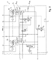
- the hydraulic motor unit 1 shown in FIG. 1 comprises two hydraulic motors 2 and 3 each designed as axial piston machines, which are arranged with their motor shafts 4 and 5 coaxial with one another and accommodated in a common motor housing 7.
- the two motor shafts 4 and 5 are rotatably connected to each other by a clutch 6, so that the two hydraulic motors 2 and 3 are synchronously operable with each other.
- the motor shaft 4 comes out of the motor housing 7 out.
- each of the hydraulic motors 2 and 3 swash plates 9 and 10, which are adjustable in their inclination, so that the displacement of the hydraulic motors 2 and 3 and thus their torque and speed is adjustable.
- the operation of the hydraulic motor unit 1 is controlled by the hydraulic circuit 11 shown in Fig. 2 and the hydraulic control means thereof which are controllable by an electronic control means.
- the aforementioned swash plates 9 and 10 of the two hydraulic motors 2 and 3 can be adjusted via the hydraulic circuit 11 and its hydraulic control elements and the clutch 6 can be engaged and disengaged.
- the two hydraulic motors 2 and 3 are supplied depending on the desired direction of rotation via the working ports A and B pressurized hydraulic fluid, depending on the desired direction of rotation of one port, the high pressure side and the other port forms the low pressure side.
- the hydraulic pressure provided by the working ports A and B could be varied to change the torque.
- this can be the swash plates 9 and 10 and thus the intake volume the two hydraulic motors 2 and 3 via control means 12 and 13 are set, each comprising a control cylinder 14 and hydraulic controls 15 for controlling the actuator cylinder 14 acting pressure.
- the swash plates 9 and 10 are set to maximum displacement.
- the auxiliary pressure G (see Figure 2) is applied and the valves E1 and E2 occupied with maximum current, so that the valves E1 and E2 through.
- the check valves SVA and SVB are open, whereby the hydraulic pressure is given by the working ports A and B ago on the hydraulic motors 2 and 3.
- the hydraulic motors 2 and 3 thereby generate in one or the other direction of rotation by the maximum pressure at the working port A and B, the maximum drive torque.
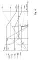
- This operating state shows the flowchart of Figure 4 until the time t 1 .
- both the rotational speed of the motor shafts 4 and 5 of the two hydraulic motors 2 and 3 and the flow rate Qp initially increase continuously.
- the rotational speeds of the two motor shafts 4 and 5 are synchronous with each other at this time, since the two motor shafts 4 and 5 are locked together by the coupling 6.
- the drive current E2 and thus the displacement V gM2 of the hydraulic motor 3 are continuously driven to zero until time t 3 , so that at time t 3 the second hydraulic motor 3 idles , so to speak, without any contribution.
- the pressure has become zero, so that the blocking valves SVA and SVB lock the high-pressure side or the low-pressure side of the engine depending on the direction of rotation due to the lack of pressure control on the directional control valves 16 and 17.
- the still rotating hydraulic motor 3 can suck in oil via the check valves R VA and R VB (see Figure 2) so that, depending on the accuracy of the zero position, no vacuum can occur at any of the connections.
- the hydraulic motor 3 is thus hydraulically uncoupled. He walks with it, without applying a drive or braking torque.
- the hydraulic motor unit 1 is operated solely by the other hydraulic motor 2.
- the coupling 6 which is shown in more detail in Figure 3, this is hydraulically actuated. It comprises, in a clutch housing 20 at least partially formed by the motor housing 7, a large actuating piston 21 and a small actuating piston 22 located opposite it, which are axially displaceably guided in a connecting cylinder 30 and movable in the direction of the longitudinal axes of the motor shafts 4 and 5.
- a toothed coupling sleeve 23 is supported via an angular contact ball bearing 25, which can engage in a corresponding toothing on the motor shaft 4 and sits on this longitudinally displaceable.
- Said toothed coupling sleeve 23 carries on its outer circumference further a plate set 29, which is acted upon by a pressure plate 27 and the angular contact ball bearing 25 from the large actuating piston 21 forth with axial pressure.
- an angular contact ball bearing 26 is supported, on which a toothed driving sleeve 24 is seated, which sits with its teeth on the motor shaft 5 of the second hydraulic motor 3 in a rotationally fixed engagement and on the Motor shaft 5 is also axially displaceable.
- the drive sleeve 24 carries on a projecting beyond the coupling sleeve 23 portion radially inwardly projecting a plate set 29 which is engageable with the set of plates on the coupling sleeve 23 in engagement.
- a thrust washer 28 the drive sleeve 24 and the angular contact ball bearing 26 of the plate set 29 can be acted upon by the small actuating piston 22 forth in the opposite direction with axial pressure.
- the clutch is controlled by pressurizing and disengaging the two actuating pistons 21 and 22 with hydraulic pressure, as follows:
- the hydraulically and mechanically switched-off hydraulic motor 3 is first accelerated again by switching on the high-pressure supply and swinging out the swash plate 10 until the speed of the hydraulic motor 3 substantially corresponds to the speed of the hydraulic motor 2.
- This can be supported by a synchronizing device, which can have a rotational speed sensor for detecting the rotational speed deviation between the two motor shafts 4 and 5 and possibly a position detection of the teeth on the shafts or a synchronizing ring, wherein the rotational speed can be adjusted by means of a corresponding change of the driving current E2 of the hydraulic motor 3 can be acted upon accordingly.
- the plate set 29 of the clutch 6 act.
Landscapes
- Engineering & Computer Science (AREA)
- General Engineering & Computer Science (AREA)
- Mechanical Engineering (AREA)
- Control Of Fluid Gearings (AREA)
- Hydraulic Clutches, Magnetic Clutches, Fluid Clutches, And Fluid Joints (AREA)
- Fluid-Pressure Circuits (AREA)
- Seal Device For Vehicle (AREA)
- Valve Device For Special Equipments (AREA)
- Vehicle Body Suspensions (AREA)
- Motor Power Transmission Devices (AREA)
- Auxiliary Drives, Propulsion Controls, And Safety Devices (AREA)
Abstract
Description
Die vorliegende Erfindung betrifft eine Antriebsvorrichtung für ein Fahrzeug und/oder eine Baumaschine, mit einer Hydraulikmotoreinheit, die zwei hintereinander geschaltete Hydraulikmotoren aufweist, deren Motorwellen durch eine Kupplung miteinander drehfest verbindbar sind.The present invention relates to a drive device for a vehicle and / or a construction machine, comprising a hydraulic motor unit, which has two hydraulic motors connected in series, whose motor shafts can be connected to one another in a rotationally fixed manner by a clutch.
Solche Antriebseinrichtungen mit einer Hydraulikmotoreinheit finden regelmäßig bei Baumaschinen Verwendung und können als Einzelradantrieb eingebaut sein oder mit ihrer Motorwelle das Antriebsritzel eines Getriebes, einer Antriebsachse oder auch die Welle eines Hubantriebes antreiben. Durch die beiden hintereinander geschalteten Hydraulikmotoren können insbesondere beim Anfahren hohe Drehmomente erzeugt werden. Nach Überwindung des Anfahrwiderstandes ist bei höheren Geschwindigkeiten allerdings ein solches hohes Drehmoment nicht mehr notwendig. Hier wäre es wünschenswert, mit geringeren Verlusten fahren zu können.Such drive means with a hydraulic motor unit are regularly used in construction machinery and can be installed as a single-wheel drive or drive the drive pinion of a transmission, a drive axle or the shaft of a linear actuator with its motor shaft. By the two series-connected hydraulic motors high torques can be generated especially when starting. After overcoming the starting resistance, however, such high torque is no longer necessary at higher speeds. Here it would be desirable to be able to drive with lower losses.
Eine Antriebsvorrichtung mit einer Hydraulikmotoreinheit der vorgenannten Art zeigt beispielsweise die
Der vorliegenden Erfindung liegt hiervon ausgehend die Aufgabe zugrunde, eine verbesserte Antriebsvorrichtung der eingangs genannten Art zu schaffen, die Nachteile des Standes der Technik vermeidet und letzteren in vorteilhafter Weise weiterbildet. Vorzugsweise soll die Antriebseinrichtung dahingehend verbessert werden, dass bei höheren Geschwindigkeiten die Antriebsvorrichtung geringere Verluste erzeugt.The present invention is based on the object to provide an improved drive device of the type mentioned above, which avoids the disadvantages of the prior art and further develops the latter in an advantageous manner. Preferably, the drive device is to be improved so that at higher speeds, the drive device generates lower losses.
Erfindungsgemäß wird diese Aufgabe durch eine Antriebsvorrichtung gemäß Anspruch 1 gelöst. Bevorzugte Ausgestaltungen der Erfindung sind Gegenstand der abhängigen Ansprüche.According to the invention, this object is achieved by a drive device according to claim 1. Preferred embodiments of the invention are the subject of the dependent claims.
Erfindungsgemäß wird also vorgeschlagen, bei dem Doppelmotor eine hydraulische und mechanische Trennung der beiden Hydraulikmotoren vorzusehen. Die Kupplung ist erfindungsgemäß lösbar ausgebildet und kann durch eine Betätigungsvorrichtung auch im Betrieb der Hydraulikmotoreinheit aus- und eingekuppelt werden. Zumindest einer der Hydraulikmotoren ist unabhängig vom Betrieb des anderen Hydraulikmotors hydraulisch abschaltbar ausgebildet, so dass insbesondere bei höheren Geschwindigkeiten die Antriebseinrichtung mit nur einem Hydraulikmotor fahren kann. Da der andere Hydraulikmotor mechanisch ausgekuppelt und abgeschaltet werden kann, können dessen Schleppverluste völlig beseitigt und diese damit insgesamt minimiert werden. Nichtsdestotrotz erlaubt die ein- und auskuppelbare Ausbildung der Verbindung der beiden Hydraulikmotoren auch im Betrieb bei laufendem Motor und Drehmomenterzeugung jederzeit, den abgeschalteten Hydraulikmotor bei Bedarf wieder zuzuschalten, beispielsweise wenn große Bremsmomente erzeugt werden sollen oder bei Bergfahrten wieder größere Antriebsmomente benötigt werden. Um insbesondere im ausgekuppelten Zustand eines der Aggregate abschalten zu können, ist insbesondere der hydraulische Schaltkreis zur Ansteuerung und/oder zur Versorgung des jeweiligen Hydraulikmotors derart ausgebildet, dass dieser Hydraulikmotor drucklos schaltbar ist. Grundsätzlich wäre es auch denkbar, bei weiterhin anstehendem Hydraulikdruck lediglich das Schluckvolumen des jeweiligen Hydraulikmotors auf Null zu stellen. Die vorgenannte Drucklosschaltung des Hydraulikmotors ist jedoch im Hinblick auf eine Minimierung der Verluste vorteilhaft.According to the invention, it is therefore proposed to provide a hydraulic and mechanical separation of the two hydraulic motors in the double engine. According to the invention, the coupling is detachably designed and can also be engaged and disengaged by an actuating device during operation of the hydraulic motor unit. At least one of the hydraulic motors is hydraulically switched off independently of the operation of the other hydraulic motor, so that in particular at higher speeds, the drive device can drive with only one hydraulic motor. Since the other hydraulic motor can be mechanically disengaged and switched off, its drag losses can be completely eliminated and thus minimized overall. Nonetheless, the engageable and disengageable Training the connection of the two hydraulic motors in operation with the engine running and torque generation at any time, the switched-off hydraulic motor switch back on demand, for example, when large braking torques are to be generated or when driving uphill again larger driving torques are needed. In order to be able to switch off one of the units, in particular in the disengaged state, in particular the hydraulic circuit for controlling and / or supplying the respective hydraulic motor is designed such that this hydraulic motor can be switched without pressure. In principle, it would also be conceivable to set only the displacement volume of the respective hydraulic motor to zero while the hydraulic pressure is still present. However, the aforementioned depressurization of the hydraulic motor is advantageous in terms of minimizing the losses.
In Weiterbildung der Erfindung wird das Ein- und Auskuppeln der Kupplung zwischen den beiden Motorwellen von einer Steuereinrichtung nach einem vorbestimmten Ablauf gesteuert. Die Steuereinrichtung kann insbesondere eine Drehzahlerfassungsvorrichtung zur Erfassung der Motorwellendrehzahl aufweisen und das hydraulische und/oder mechanische Wegschalten eines der Hydraulikmotoren in Abhängigkeit der Motordrehzahl steuern. Insbesondere kann die Steuereinrichtung bei Überschreiten einer vorbestimmten Motordrehzahl einen der Hydraulikmotoren hydraulisch gegen Null steuern, so dass dieser Hydraulikmotor kein Drehmoment mehr abgibt und sozusagen leer mitläuft. Alternativ oder zusätzlich kann die Steuereinrichtung bei Überschreiten der genannten vorbestimmten Drehzahl den Hydraulikmotor durch Lösen der Kupplung zwischen den beiden Motorwellen auch mechanisch von dem anderen Hydraulikmotor abkuppeln, so dass das Drehmoment der Antriebsvorrichtung lediglich noch durch den anderen Hydraulikmotor geliefert wird.In a further development of the invention, the engagement and disengagement of the clutch between the two motor shafts is controlled by a control device according to a predetermined sequence. In particular, the control device can have a speed detection device for detecting the motor shaft speed and control the hydraulic and / or mechanical disconnection of one of the hydraulic motors as a function of the engine speed. In particular, when a predetermined engine speed is exceeded, the control device can hydraulically control one of the hydraulic motors to zero, so that this hydraulic motor no longer delivers any torque and, as it were, runs along with it. Alternatively or additionally, when the predetermined rotational speed is exceeded, the control device can also mechanically decouple the hydraulic motor from the other hydraulic motor by releasing the clutch between the two motor shafts, so that the torque of the drive device is merely supplied by the other hydraulic motor.
Beim Abschalten des einen Hydraulikmotors wird dabei vorteilhafterweise vor dem Lösen der Kupplung zunächst von hydraulischen Steuermitteln das Drehmoment des abzukuppelnden Hydraulikmotors gegen Null gesteuert und erst in einem darauf folgenden Schritt die Kupplung gelöst, so dass Drehmomentstöße vermieden und ein sanftes Abschalten erreicht werden kann. Umgekehrt wird vor dem Einkuppeln des abgeschalteten Hydraulikmotors vorteilhafterweise die Drehzahl des einzukuppelnden Hydraulikmotors etwa auf die Drehzahl des laufenden Hydraulikmotors gesteuert, so dass beim Einkuppeln der Kupplung keine größeren Drehzahlunterschiede zwischen den beiden Motorwellen zu überwinden sind.When switching off the one hydraulic motor, the torque of the hydraulic motor to be decoupled is advantageously controlled to zero before releasing the clutch, and the clutch is first released by hydraulic control means in a subsequent step, so that torque surges are avoided and a gentle shutdown can be achieved. Conversely, before engaging the cut-off hydraulic motor advantageously the speed of the hydraulic motor to be coupled is controlled approximately to the speed of the running hydraulic motor, so that when coupling the clutch no major speed differences between the two motor shafts are overcome.
Insbesondere umfassen die hydraulischen Steuermittel zur Steuerung des Drehmoments des Hydraulikmotors Mittel zur Veränderung dessen Schluckvolumens. Gegebenenfalls kann auch durch eine Änderung des Versorgungsdrucks das Drehmoment in der gewünschten Weise eingestellt werden. Über die vorgenannten Mittel zur Veränderung des Schluckvolumens und/oder die Druckänderung kann auch die gewünschte Steuerung der Drehzahl des einzukuppelnden Hydraulikmotors erreicht werden.In particular, the hydraulic control means for controlling the torque of the hydraulic motor comprise means for varying the volume of the latter. Optionally, the torque can be adjusted in the desired manner by changing the supply pressure. The desired control of the rotational speed of the hydraulic motor to be engaged can also be achieved via the abovementioned means for changing the displacement volume and / or the pressure change.
Um beim Einkuppeln Drehzahlunterschiede zwischen den beiden Motorwellen bestmöglich zu vermeiden, kann die Steuereinrichtung eine Synchronisiereinrichtung aufweisen, die mittels einer Drehzahlerfassungseinrichtung eine Drehzahlabweichung zwischen den Motorwellen der beiden Hydraulikmotoren erfasst und die hydraulischen Steuermittel zur Steuerung der Drehzahl des einzukuppelnden Hydraulikmotors in Abhängigkeit der erfassten Drehzahlabweichung ansteuert. Hierdurch kann die Drehzahlabweichung gegen Null geregelt werden, bevor die Kupplung in ihre Eingriffsstellung gebracht wird.In order to optimally avoid differences in speed between the two motor shafts during engagement, the control device may comprise a synchronizer, which detects a speed deviation between the motor shafts of the two hydraulic motors by means of a speed detection device and controls the hydraulic control means for controlling the speed of the hydraulic motor to be engaged as a function of the detected speed deviation. As a result, the speed deviation can be controlled to zero before the clutch is brought into its engaged position.
Die beiden Hydraulikmotoren können verschieden ausgebildet sein. Grundsätzlich kommt jeder Hydraulikmotor mit Durchtrieb in Betracht. Beispielsweise können Zahnrad- oder Flügelzellenmotoren zum Einsatz kommen. Nach einer bevorzugten Ausführung der Erfindung sind Axialkolbenmotoren hintereinander geschaltet, deren Schluckvolumen mittels verstellbarer Schrägscheiben verändert werden kann. Zweckmäßigerweise besitzen beide Hydraulikmotoren dieselbe Ausbildung vorzugsweise als Axialkolbenmaschinen, die mit ihren Motorwellen koaxial zueinander angeordnet sein und ein gemeinsames Motorgehäuses, das zweckmäßigerweise mehrteilig ausgebildet ist, aufweisen können.The two hydraulic motors can be designed differently. In principle, every hydraulic motor with through drive is considered. For example, gear or vane motors may be used. According to a preferred embodiment of the invention axial piston motors are connected in series, the displacement of which can be changed by means of adjustable swash plates. Conveniently, both hydraulic motors have the same design preferably as axial piston machines, which are arranged coaxially with each other with their motor shafts and a common motor housing, which is expediently designed in several parts, may have.
Die Kupplung zwischen den Motorwellen der beiden Hydraulikmotoren kann grundsätzlich verschieden ausgebildet sein. Nach einer vorteilhaften Ausführung der Erfindung ist die Kupplung hydraulisch betätigbar und von der Betätigungsvorrichtung mit einem veränderbaren Steuerdruck beaufschlagbar, in Abhängigkeit dessen die Kupplung ein- und auskuppelt.The coupling between the motor shafts of the two hydraulic motors can basically be designed differently. According to an advantageous embodiment of the invention, the clutch is hydraulically actuated and acted upon by the actuating device with a variable control pressure, depending on the clutch on and disengages.
Vorteilhafterweise kann die Kupplung sowohl Reibkupplungsmittel als auch Formschlusskupplungsmittel aufweisen, die nach einer vorbestimmten Abfolge betätigbar sind. Beispielsweise kann die Kupplung sowohl eine Lamellenkupplungseinrichtung und eine auf die jeweilige Motorwelle formschlüssig aufschiebbare, insbesondere verzahnte Kupplungshülse aufweisen. Das Vorsehen von sowohl Reibkupplungsmitteln als auch Formschlusskupplungsmitteln erlaubt es, beim Einkuppeln zunächst einen Reibschluss zwischen den beiden Motorwellen herzustellen, über den ggf. noch bestehende Drehzahlabweichungen ausgeglichen werden können. Greifen die Reibschlussmittel so weit, dass die beiden Motorwellen synchron zueinander laufen, können die Formschlussmittel sanft in Eingriff gebracht werden.Advantageously, the coupling can comprise both friction coupling means and form-locking coupling means, which can be actuated according to a predetermined sequence. For example, the coupling may have both a multi-plate clutch device and a coupling sleeve which is in particular form-fitting manner and can be pushed onto the respective motor shaft. The provision of both friction clutch means and positive-locking clutch means makes it possible to initially produce a frictional engagement between the two motor shafts during engagement, via which possibly existing speed deviations can be compensated. Grasping the frictional engagement means so far that the two motor shafts run synchronously to each other, the interlocking means can be gently engaged.
Die vorliegende Erfindung wird nachfolgend anhand eines bevorzugten Ausführungsbeispiels und zugehöriger Zeichnungen näher erläutert. In den Zeichnungen zeigen:
- Fig. 1:
- einen Längsschnitt durch die Hydraulikmotoreinheit der Antriebsvorrichtung nach einer bevorzugten Ausführung der Erfindung,
- Fig. 2:
- den hydraulischen Schaltkreis zur Steuerung und Versorgung der beiden Hydraulikmotoren der Hydraulikmotoreinheit aus Fig. 1 in schematischer Darstellung,
- Fig. 3:
- eine vergrößerte Schnittansicht der Kupplung zwischen den Motorwellen der beiden Hydraulikmotoren der Hydraulikmotoreinheit aus Fig. 1, und
- Fig. 4:
- ein Ablaufdiagramm, das den Verlauf verschiedener Steuer- und Betriebsparameter der Hydraulikmotoreinheit aus Fig. 1 über der Zeit für einen Anfahrvorgang und einen darauf folgenden Abschaltvorgang zeigt.
- Fig. 1:
- a longitudinal section through the hydraulic motor unit of the drive device according to a preferred embodiment of the invention,
- Fig. 2:
- 1 the hydraulic circuit for controlling and supplying the two hydraulic motors of the hydraulic motor unit of FIG. 1 in a schematic representation,
- 3:
- an enlarged sectional view of the coupling between the motor shafts of the two hydraulic motors of the hydraulic motor unit of Fig. 1, and
- 4:
- a flowchart showing the course of various control and operating parameters of the hydraulic motor unit of FIG. 1 over time for a startup and a subsequent shutdown.
Die in Figur 1 gezeigte Hydraulikmotoreinheit 1 umfasst zwei jeweils als Axialkolbenmaschinen ausgebildete Hydraulikmotoren 2 und 3, die mit ihren Motorwellen 4 und 5 koaxial zueinander angeordnet und in einem gemeinsamen Motorgehäuse 7 aufgenommen sind. Die beiden Motorwellen 4 und 5 sind durch eine Kupplung 6 miteinander drehfest verbindbar, so dass die beiden Hydraulikmotoren 2 und 3 synchron miteinander betreibbar sind. Auf der in Figur 1 linken Seite des Motorgehäuses 7 tritt die Motorwelle 4 aus dem Motorgehäuse 7 heraus. Mit dem entsprechenden Antriebsabschnitt 8 kann ein einzelnes Rad eines Fahrzeugs, eine Achse oder auch ein Hubwerk einer Baumaschine ggf. unter Zwischenschaltung eines Getriebes angetrieben werden.The hydraulic motor unit 1 shown in FIG. 1 comprises two
Wie Figur 1 zeigt, umfasst jeder der Hydraulikmotoren 2 und 3 Schrägscheiben 9 und 10, die in ihrer Neigung verstellbar sind, so dass das Schluckvolumen der Hydraulikmotoren 2 und 3 und damit deren Drehmoment und Geschwindigkeit einstellbar ist. Der Betrieb der Hydraulikmotoreinheit 1 wird von dem in Figur 2 gezeigten hydraulischen Schaltkreis 11 und dessen hydraulische Steuermittel gesteuert, die von einer elektronischen Steuereinrichtung ansteuerbar sind. Insbesondere können die vorgenannten Schrägscheiben 9 und 10 der beiden Hydraulikmotoren 2 und 3 über den hydraulischen Schaltkreis 11 und dessen hydraulische Steuerelemente verstellt und die Kupplung 6 ein- und ausgekuppelt werden.As Figure 1 shows, each of the
Im Betrieb wird den beiden Hydraulikmotoren 2 und 3 je nach gewünschter Drehrichtung über die Arbeitsanschlüsse A bzw. B unter Druck stehendes Hydraulikfluid zugeführt, wobei je nach gewünschter Drehrichtung der eine Anschluss die Hochdruckseite und der andere Anschluss die Niederdruckseite bildet. Zur Drehmomentveränderung könnte grundsätzlich natürlich der Hydraulikdruck, der von den Arbeitsanschlüssen A bzw. B. bereitgestellt wird, variiert werden. Insbesondere jedoch können hierzu die Schrägscheiben 9 und 10 und damit das Schluckvolumen der beiden Hydraulikmotoren 2 und 3 über Steuermittel 12 bzw. 13 eingestellt werden, die jeweils einen Stellzylinder 14 sowie hydraulische Steuerelemente 15 zur Steuerung des den Stellzylinder 14 beaufschlagenden Drucks umfassen.In operation, the two
Soll die Hydraulikmotoreinheit 1 mit maximalem Drehmoment angefahren werden, werden zunächst die Schrägscheiben 9 und 10 auf maximales Schluckvolumen gestellt. Hierzu wird der Hilfsdruck G (vgl. Figur 2) angelegt und die Ventile E1 und E2 mit maximalem Strom belegt, so dass die Ventile E1 und E2 durchschalten. Hierdurch öffnen die nachgeschalteten Steuerventile 12 bzw. 13, wodurch die großen Stellkolbenflächen der Stellzylinder 14 derart mit Druck beaufschlagt werden, dass die damit verbundenen Schrägscheiben 9 und 10 auf volles Schluckvolumen gestellt werden. Durch den von der großen Stellkolbenfläche des Stellzylinders 14 des Hydraulikmotors 3 auf die Wegeventile 16 und 17 rückgeführten Druck sind die Sperrventile SVA und SVB offen, wodurch der Hydraulikdruck von den Arbeitsanschlüssen A bzw. B her auf die Hydraulikmotoren 2 und 3 gegeben wird. Die Hydraulikmotoren 2 und 3 erzeugen hierdurch in der einen oder in der anderen Drehrichtung durch den maximalen Druck an dem Arbeitsanschluss A bzw. B das maximale Antriebsdrehmoment. Diesen Betriebszustand zeigt das Ablaufdiagramm nach Figur 4 bis zum Zeitpunkt t1.If the hydraulic motor unit 1 is to be approached with maximum torque, first the
Dementsprechend steigen sowohl die Drehzahl der Motorwellen 4 und 5 der beiden Hydraulikmotoren 2 und 3 als auch der Förderstrom Qp zunächst kontinuierlich an. Die Drehzahlen der beiden Motorwellen 4 und 5 sind zu diesem Zeitpunkt zueinander synchron, da die beiden Motorwellen 4 und 5 durch die Kupplung 6 miteinander verriegelt sind.Accordingly, both the rotational speed of the
Erreicht die Motordrehzahl im Zeitpunkt t2 einen vorbestimmten Wert (vgl. Figur 4), wird das Drehmoment des zweiten Hydraulikmotors 3 reduziert, und zwar durch Reduzierung des Ansteuerstromes E2 und/oder des Hydraulikdrucks. Hierdurch verringert sich das Schluckvolumen VgM2 und dadurch das Drehmoment. Bei gleich bleibender Versorgungsmenge erhöht sich die Drehzahl mit abnehmendem Schluckvolumen.When the engine speed reaches a predetermined value at the time t 2 (see Fig. 4), the torque of the second
Wie Figur 4 zeigt, wird bis zum Zeitpunkt t3 kontinuierlich der Ansteuerstrom E2 und damit das Schluckvolumen VgM2 des Hydraulikmotors 3 gegen Null gefahren, so dass im Zeitpunkt t3 der zweite Hydraulikmotor 3 sozusagen ohne Beitrag leer mitläuft. Auf der großen Stellkolbenfläche des Stellzylinders 14 ist der Druck Null geworden, so dass durch die fehlende Druckansteuerung an den Wegeventilen 16 bzw. 17 die Sperrventile SVA und SVB je nach Drehrichtung die Hochdruckseite oder die Niederdruckseite des Motors sperren. Über die Rückschlagventile RVA und RVB (vgl. Figur 2) kann der noch mitdrehende Hydraulikmotor 3 Öl nachsaugen, damit je nach Genauigkeit der Nulllage an keinem der Anschlüsse Unterdruck entstehen kann. Der Hydraulikmotor 3 ist damit hydraulisch abgekuppelt. Er läuft mit, ohne ein Antriebs- oder Bremsmoment aufzubringen. Die Hydraulikmotoreinheit 1 wird allein von dem anderen Hydraulikmotor 2 betrieben.As shown in FIG. 4, the drive current E2 and thus the displacement V gM2 of the hydraulic motor 3 are continuously driven to zero until time t 3 , so that at time t 3 the second
Um die Schleppverluste noch weiter zu reduzieren, wird bei Erreichen des Zeitpunktes t3 die Kupplung 6 zwischen den beiden Motorwellen 4 und 5 gelöst und damit der Hydraulikmotor 3 auch mechanisch abgekuppelt. Die Kupplung 6, die in Figur 3 näher gezeigt ist, ist hierzu hydraulisch betätigbar. Sie umfasst in einem von dem Motorgehäuse 7 zumindest teilweise gebildeten Kupplungsgehäuse 20 einen großen Stellkolben 21 sowie einen diesem gegenüberliegenden kleinen Stellkolben 22, die in einem Verbindungszylinder 30 jeweils axial verschieblich geführt und in Richtung der Längsachsen der Motorwellen 4 und 5 verfahrbar sind. An dem großen Stellkolben 21 ist über ein Schrägkugellager 25 eine verzahnte Kupplungshülse 23 abgestützt, die in eine entsprechende Verzahnung auf der Motorwelle 4 eingreifen kann und auf dieser längsverschieblich sitzt. Die genannte verzahnte Kupplungshülse 23 trägt an ihrem Außenumfang weiterhin einen Lamellensatz 29, der über eine Druckscheibe 27 und das Schrägkugellager 25 von dem großen Stellkolben 21 her mit axialem Druck beaufschlagbar ist.In order to reduce the drag losses even further, upon reaching the time t 3, the clutch 6 is released between the two
An dem kleinen Stellkolben 22 ist ebenfalls ein Schrägkugellager 26 abgestützt, an dem eine verzahnte Mitnehmerhülse 24 sitzt, die mit ihrer Verzahnung auf der Motorwelle 5 des zweiten Hydraulikmotors 3 in drehfestem Eingriff sitzt und auf der Motorwelle 5 ebenfalls axial verschieblich ist. Die Mitnehmerhülse 24 trägt an einem über die Kupplungshülse 23 vorspringenden Abschnitt radial nach innen vorspringend einen Lamellensatz 29, der mit dem Lamellensatz auf der Kupplungshülse 23 in Eingriff bringbar ist. Über eine Druckscheibe 28, die Mitnehmerhülse 24 und das Schrägkugellager 26 ist der Lamellensatz 29 von dem kleinen Stellkolben 22 her in entgegengesetzter Richtung mit axialem Druck beaufschlagbar.At the
Die Kupplung wird durch Beaufschlagen der beiden Stellkolben 21 und 22 mit Hydraulikdruck in und außer Eingriff gesteuert, und zwar folgendermaßen:The clutch is controlled by pressurizing and disengaging the two actuating
Um nach Erreichen des Zeitpunktes t3 (vgl. Figur 4) den Hydraulikmotor 3 abzukuppeln, wird der an dem großen Stellkolben 21 anliegende Steuerdruck x (vgl. Figuren 1 und 2) reduziert, so dass der an dem kleinen Stellkolben 22 konstant anliegende Stelldruck, der in der gezeichneten Ausführung 30 bar betragen kann, die gesamte Kupplungsanordnung gemäß Figur 1 nach links schieben kann, so dass die Kupplungshülse 23 von der Motorwelle 5 des zweiten Hydraulikmotors 3 herunter geschoben wird. Der Stellkolben 22 schiebt über das Schrägkugellager 26, die Mitnehmerhülse 24, die Druckscheibe 28 und den Lamellensatz 29 auch die Kupplungshülse 23 nach links, bis diese vom Ende der Motorwelle 5 rutscht. In diesem Zustand wird der zweite Hydraulikmotor 3 über den noch in Eingriff befindlichen Lamellensatz 29 mitgenommen. Wird der Steuerdruck x jedoch noch weiter reduziert, reicht die Reibung des Lamellensatzes 29 für die weitere Mitnahme nicht mehr aus, so dass der Hydraulikmotor 3 gänzlich abgekuppelt wird und mangels eigenem Drehmoment stehen bleibt. Dieser Zustand ist im Zeitpunkt t4 erreicht (vgl. Figur 4).In order to decouple the
Soll das allein von dem Hydraulikmotor 2 aufgebrachte Antriebsmoment der Hydraulikmotoreinheit 1 weiter reduziert werden, kann durch Reduzierung des Ansteuerstromes E1 sodann weiterhin auch das Schluckvolumen VgM1 des Hydraulikmotors 2 und damit dessen Drehmoment reduziert werden. Dies zeigt die Figur 4 in dem Zeitraum zwischen t4 und t5.If the drive torque of the hydraulic motor unit 1 applied solely by the
Soll zu einem späteren Zeitpunkt der zweite Hydraulikmotor 3 wieder eingekuppelt werden, wird grundsätzlich in umgekehrter Reihenfolge vorgegangen. Der hydraulisch und mechanisch abgeschaltete Hydraulikmotor 3 wird zunächst wieder durch Zuschaltung der Hochdruckversorgung und Ausschwenken der Schrägscheibe 10 beschleunigt, bis die Drehzahl des Hydraulikmotors 3 im wesentlichen der Drehzahl des Hydraulikmotors 2 entspricht. Dies kann von einer Synchronisiereinrichtung, die einen Drehzahlsensor zur Erfassung der Drehzahlabweichung zwischen den beiden Motorwellen 4 und 5 sowie evtl. eine Positionserfassung der Zähne auf den Wellen bzw. einen Synchronisierring aufweisen kann, unterstützt werden, wobei über entsprechende Veränderung des Ansteuerstromes E2 auf die Drehzahl des Hydraulikmotors 3 entsprechend eingewirkt werden kann. Als Teil der Synchronisiereinrichtung kann hierbei auch der Lamellensatz 29 der Kupplung 6 wirken. Wird der auf den großen Stellkolben 21 wirkende Steuerdruck bei Null beginnend nach oben gefahren, werden über die Druckscheibe 27 die Lamellen des Lamellensatzes 29 aufeinander gepresst, so dass der Hydraulikmotor 2 im Leerlauf mitgenommen und auf die Drehzahl des Hydraulikmotors 2 beschleunigt wird. Nach einer vorbestimmten Beschleunigungszeit und/oder nach Unterschreiten einer vorbestimmten Drehzahlabweichung kann der Steuerdruck x über einen vorbestimmten Wert hinaus erhöht werden, so dass der Stellkolben 21 die gesamte Kupplungsanordnung gemäß Figur 1 nach rechts und damit die Kupplungshülse 23 auf die Motorwelle 5 schiebt, wodurch die beiden Motorwellen 4 und 5 drehfest miteinander verbunden werden. Hierdurch sind die beiden Motoren 2 und 3 wieder mechanisch miteinander verriegelt.If the second
Claims (10)
Applications Claiming Priority (1)
| Application Number | Priority Date | Filing Date | Title |
|---|---|---|---|
| DE202005007970U DE202005007970U1 (en) | 2005-05-20 | 2005-05-20 | driving device |
Publications (3)
| Publication Number | Publication Date |
|---|---|
| EP1724499A2 true EP1724499A2 (en) | 2006-11-22 |
| EP1724499A3 EP1724499A3 (en) | 2009-06-24 |
| EP1724499B1 EP1724499B1 (en) | 2010-11-10 |
Family
ID=36928629
Family Applications (1)
| Application Number | Title | Priority Date | Filing Date |
|---|---|---|---|
| EP06009838A Not-in-force EP1724499B1 (en) | 2005-05-20 | 2006-05-12 | Drive unit |
Country Status (3)
| Country | Link |
|---|---|
| EP (1) | EP1724499B1 (en) |
| AT (1) | ATE487900T1 (en) |
| DE (2) | DE202005007970U1 (en) |
Families Citing this family (1)
| Publication number | Priority date | Publication date | Assignee | Title |
|---|---|---|---|---|
| EP3009716A1 (en) * | 2014-10-16 | 2016-04-20 | Dana Italia S.p.A. | Dual motor drive unit and method of drivingly engaging a first motor of a dual motor drive unit with an output shaft |
Citations (5)
| Publication number | Priority date | Publication date | Assignee | Title |
|---|---|---|---|---|
| EP0026115A2 (en) * | 1979-09-06 | 1981-04-01 | ETAT-FRANCAIS représenté par le Délégué Général pour l' Armement | Hydrostatic transmissions with a wide working range |
| EP0483543A1 (en) * | 1990-10-31 | 1992-05-06 | Liebherr-Werk Bischofshofen GmbH | Hydrostatic transmission, preferably for an earth moving machine, for example a shovel loader |
| WO1997029308A1 (en) * | 1996-02-07 | 1997-08-14 | Komatsu Uk Ltd. | Control system for hydraulic drive |
| DE19751001A1 (en) * | 1997-11-18 | 1999-05-20 | Zahnradfabrik Friedrichshafen | Method of preventing thrust interruption with switching on and off of hydro-motors |
| DE202004009767U1 (en) * | 2004-05-10 | 2004-09-02 | Zf Friedrichshafen Ag | Drive for a mobile vehicle, especially a machine such as a wheel loader, comprises a motor that is adjusted to a zero stroke volume and is separated from a common high-pressure line at the maximum speed of a driven shaft |
Family Cites Families (3)
| Publication number | Priority date | Publication date | Assignee | Title |
|---|---|---|---|---|
| US5207060A (en) * | 1991-09-03 | 1993-05-04 | Sauer, Inc. | Tandem hydraulic motor |
| DE19610821C2 (en) * | 1996-03-19 | 2002-11-28 | Sauer Sundstrand Gmbh & Co | Hydrostatic motor with two shaft ends and clutch |
| DE202004009821U1 (en) * | 2004-05-10 | 2004-09-23 | Zf Friedrichshafen Ag | Hydraulic driving mechanism for mobile vehicles like diggers, loaders and road/motor graders has a hydraulic motor with feed/return of pressurized substance and step-down gearing with power take-off |
-
2005
- 2005-05-20 DE DE202005007970U patent/DE202005007970U1/en not_active Expired - Lifetime
-
2006
- 2006-05-12 AT AT06009838T patent/ATE487900T1/en active
- 2006-05-12 DE DE502006008262T patent/DE502006008262D1/en active Active
- 2006-05-12 EP EP06009838A patent/EP1724499B1/en not_active Not-in-force
Patent Citations (5)
| Publication number | Priority date | Publication date | Assignee | Title |
|---|---|---|---|---|
| EP0026115A2 (en) * | 1979-09-06 | 1981-04-01 | ETAT-FRANCAIS représenté par le Délégué Général pour l' Armement | Hydrostatic transmissions with a wide working range |
| EP0483543A1 (en) * | 1990-10-31 | 1992-05-06 | Liebherr-Werk Bischofshofen GmbH | Hydrostatic transmission, preferably for an earth moving machine, for example a shovel loader |
| WO1997029308A1 (en) * | 1996-02-07 | 1997-08-14 | Komatsu Uk Ltd. | Control system for hydraulic drive |
| DE19751001A1 (en) * | 1997-11-18 | 1999-05-20 | Zahnradfabrik Friedrichshafen | Method of preventing thrust interruption with switching on and off of hydro-motors |
| DE202004009767U1 (en) * | 2004-05-10 | 2004-09-02 | Zf Friedrichshafen Ag | Drive for a mobile vehicle, especially a machine such as a wheel loader, comprises a motor that is adjusted to a zero stroke volume and is separated from a common high-pressure line at the maximum speed of a driven shaft |
Also Published As
| Publication number | Publication date |
|---|---|
| DE502006008262D1 (en) | 2010-12-23 |
| EP1724499A3 (en) | 2009-06-24 |
| ATE487900T1 (en) | 2010-11-15 |
| DE202005007970U1 (en) | 2006-10-05 |
| EP1724499B1 (en) | 2010-11-10 |
Similar Documents
| Publication | Publication Date | Title |
|---|---|---|
| DE3917466C1 (en) | ||
| WO2006128637A1 (en) | Friction clutch having a hydraulic actuator, and drive unit having at least one such friction clutch | |
| DE1903647A1 (en) | Mechanical transmission | |
| EP3126701B1 (en) | Method for controlling an actuating assembly for a clutch, and a drive assembly having an actuating assembly | |
| DE4134658A1 (en) | DRIVE UNIT | |
| DE1949973C3 (en) | Hydrostatic unit | |
| WO2015055366A2 (en) | Hydraulic control device for an automatic transmission | |
| WO2008101459A1 (en) | Hydraulic arrangement for controlling a continuously variable conical disc transmission | |
| EP3196496B1 (en) | Hydraulic assembly for a motor vehicle drive train | |
| WO2018046144A1 (en) | Electrohydraulic system for actuating multiple-disc clutches and gear actuators with highly precise control of a plurality of transmission units simultaneously | |
| DE976055C (en) | Hydrostatic transmission, especially for motor vehicles | |
| DE2310444C3 (en) | Auxiliary friction clutch for the relative rotation of two shift gears of an unsynchronized tooth change gear | |
| WO2015144155A1 (en) | Actuator which can be drive-coupled and has a variable displacement pump | |
| WO2022012905A1 (en) | Automatic transmission for a motor vehicle, and motor vehicle | |
| DE1505413A1 (en) | Fluid power drive | |
| DE102007026133A1 (en) | manual transmission | |
| DE102004058984A1 (en) | Driving axle e.g. industrial truck driving axle has hydraulic pump with electric motor which stays in drive connection or it can be placed in drive connection and detachable coupling is downstream in differential exits and brakes | |
| WO2010057456A1 (en) | Vehicle transmission having continuously variable transmission ratio | |
| DE102008059267B4 (en) | Double clutch | |
| WO2005064187A1 (en) | Hydraulic system for two multiplate clutches | |
| DE602004008775T2 (en) | DRIVE SWITCHING DEVICE | |
| DE60036977T2 (en) | Power transmission mechanism | |
| WO2009021584A1 (en) | Manual transmission | |
| EP1724499B1 (en) | Drive unit | |
| DE102014204564A1 (en) | Device for generating and releasing a rotationally fixed connection between two shafts |
Legal Events
| Date | Code | Title | Description |
|---|---|---|---|
| PUAI | Public reference made under article 153(3) epc to a published international application that has entered the european phase |
Free format text: ORIGINAL CODE: 0009012 |
|
| AK | Designated contracting states |
Kind code of ref document: A2 Designated state(s): AT BE BG CH CY CZ DE DK EE ES FI FR GB GR HU IE IS IT LI LT LU LV MC NL PL PT RO SE SI SK TR |
|
| AX | Request for extension of the european patent |
Extension state: AL BA HR MK YU |
|
| PUAL | Search report despatched |
Free format text: ORIGINAL CODE: 0009013 |
|
| AK | Designated contracting states |
Kind code of ref document: A3 Designated state(s): AT BE BG CH CY CZ DE DK EE ES FI FR GB GR HU IE IS IT LI LT LU LV MC NL PL PT RO SE SI SK TR |
|
| AX | Request for extension of the european patent |
Extension state: AL BA HR MK YU |
|
| 17P | Request for examination filed |
Effective date: 20091127 |
|
| AKX | Designation fees paid |
Designated state(s): AT BE BG CH CY CZ DE DK EE ES FI FR GB GR HU IE IS IT LI LT LU LV MC NL PL PT RO SE SI SK TR |
|
| GRAP | Despatch of communication of intention to grant a patent |
Free format text: ORIGINAL CODE: EPIDOSNIGR1 |
|
| GRAS | Grant fee paid |
Free format text: ORIGINAL CODE: EPIDOSNIGR3 |
|
| GRAA | (expected) grant |
Free format text: ORIGINAL CODE: 0009210 |
|
| AK | Designated contracting states |
Kind code of ref document: B1 Designated state(s): AT BE BG CH CY CZ DE DK EE ES FI FR GB GR HU IE IS IT LI LT LU LV MC NL PL PT RO SE SI SK TR |
|
| REG | Reference to a national code |
Ref country code: GB Ref legal event code: FG4D Free format text: NOT ENGLISH |
|
| REG | Reference to a national code |
Ref country code: CH Ref legal event code: EP |
|
| REG | Reference to a national code |
Ref country code: IE Ref legal event code: FG4D Free format text: LANGUAGE OF EP DOCUMENT: GERMAN |
|
| REF | Corresponds to: |
Ref document number: 502006008262 Country of ref document: DE Date of ref document: 20101223 Kind code of ref document: P |
|
| REG | Reference to a national code |
Ref country code: NL Ref legal event code: VDEP Effective date: 20101110 |
|
| LTIE | Lt: invalidation of european patent or patent extension |
Effective date: 20101110 |
|
| PG25 | Lapsed in a contracting state [announced via postgrant information from national office to epo] |
Ref country code: LT Free format text: LAPSE BECAUSE OF FAILURE TO SUBMIT A TRANSLATION OF THE DESCRIPTION OR TO PAY THE FEE WITHIN THE PRESCRIBED TIME-LIMIT Effective date: 20101110 |
|
| PG25 | Lapsed in a contracting state [announced via postgrant information from national office to epo] |
Ref country code: PT Free format text: LAPSE BECAUSE OF FAILURE TO SUBMIT A TRANSLATION OF THE DESCRIPTION OR TO PAY THE FEE WITHIN THE PRESCRIBED TIME-LIMIT Effective date: 20110310 Ref country code: LV Free format text: LAPSE BECAUSE OF FAILURE TO SUBMIT A TRANSLATION OF THE DESCRIPTION OR TO PAY THE FEE WITHIN THE PRESCRIBED TIME-LIMIT Effective date: 20101110 Ref country code: CY Free format text: LAPSE BECAUSE OF FAILURE TO SUBMIT A TRANSLATION OF THE DESCRIPTION OR TO PAY THE FEE WITHIN THE PRESCRIBED TIME-LIMIT Effective date: 20101110 Ref country code: IS Free format text: LAPSE BECAUSE OF FAILURE TO SUBMIT A TRANSLATION OF THE DESCRIPTION OR TO PAY THE FEE WITHIN THE PRESCRIBED TIME-LIMIT Effective date: 20110310 Ref country code: NL Free format text: LAPSE BECAUSE OF FAILURE TO SUBMIT A TRANSLATION OF THE DESCRIPTION OR TO PAY THE FEE WITHIN THE PRESCRIBED TIME-LIMIT Effective date: 20101110 Ref country code: FI Free format text: LAPSE BECAUSE OF FAILURE TO SUBMIT A TRANSLATION OF THE DESCRIPTION OR TO PAY THE FEE WITHIN THE PRESCRIBED TIME-LIMIT Effective date: 20101110 Ref country code: SI Free format text: LAPSE BECAUSE OF FAILURE TO SUBMIT A TRANSLATION OF THE DESCRIPTION OR TO PAY THE FEE WITHIN THE PRESCRIBED TIME-LIMIT Effective date: 20101110 Ref country code: SE Free format text: LAPSE BECAUSE OF FAILURE TO SUBMIT A TRANSLATION OF THE DESCRIPTION OR TO PAY THE FEE WITHIN THE PRESCRIBED TIME-LIMIT Effective date: 20101110 Ref country code: BG Free format text: LAPSE BECAUSE OF FAILURE TO SUBMIT A TRANSLATION OF THE DESCRIPTION OR TO PAY THE FEE WITHIN THE PRESCRIBED TIME-LIMIT Effective date: 20110210 |
|
| REG | Reference to a national code |
Ref country code: IE Ref legal event code: FD4D |
|
| PG25 | Lapsed in a contracting state [announced via postgrant information from national office to epo] |
Ref country code: GR Free format text: LAPSE BECAUSE OF FAILURE TO SUBMIT A TRANSLATION OF THE DESCRIPTION OR TO PAY THE FEE WITHIN THE PRESCRIBED TIME-LIMIT Effective date: 20110211 |
|
| PG25 | Lapsed in a contracting state [announced via postgrant information from national office to epo] |
Ref country code: CZ Free format text: LAPSE BECAUSE OF FAILURE TO SUBMIT A TRANSLATION OF THE DESCRIPTION OR TO PAY THE FEE WITHIN THE PRESCRIBED TIME-LIMIT Effective date: 20101110 Ref country code: EE Free format text: LAPSE BECAUSE OF FAILURE TO SUBMIT A TRANSLATION OF THE DESCRIPTION OR TO PAY THE FEE WITHIN THE PRESCRIBED TIME-LIMIT Effective date: 20101110 Ref country code: ES Free format text: LAPSE BECAUSE OF FAILURE TO SUBMIT A TRANSLATION OF THE DESCRIPTION OR TO PAY THE FEE WITHIN THE PRESCRIBED TIME-LIMIT Effective date: 20110221 Ref country code: IE Free format text: LAPSE BECAUSE OF FAILURE TO SUBMIT A TRANSLATION OF THE DESCRIPTION OR TO PAY THE FEE WITHIN THE PRESCRIBED TIME-LIMIT Effective date: 20101110 |
|
| PG25 | Lapsed in a contracting state [announced via postgrant information from national office to epo] |
Ref country code: RO Free format text: LAPSE BECAUSE OF FAILURE TO SUBMIT A TRANSLATION OF THE DESCRIPTION OR TO PAY THE FEE WITHIN THE PRESCRIBED TIME-LIMIT Effective date: 20101110 Ref country code: SK Free format text: LAPSE BECAUSE OF FAILURE TO SUBMIT A TRANSLATION OF THE DESCRIPTION OR TO PAY THE FEE WITHIN THE PRESCRIBED TIME-LIMIT Effective date: 20101110 Ref country code: PL Free format text: LAPSE BECAUSE OF FAILURE TO SUBMIT A TRANSLATION OF THE DESCRIPTION OR TO PAY THE FEE WITHIN THE PRESCRIBED TIME-LIMIT Effective date: 20101110 Ref country code: DK Free format text: LAPSE BECAUSE OF FAILURE TO SUBMIT A TRANSLATION OF THE DESCRIPTION OR TO PAY THE FEE WITHIN THE PRESCRIBED TIME-LIMIT Effective date: 20101110 |
|
| PLBE | No opposition filed within time limit |
Free format text: ORIGINAL CODE: 0009261 |
|
| STAA | Information on the status of an ep patent application or granted ep patent |
Free format text: STATUS: NO OPPOSITION FILED WITHIN TIME LIMIT |
|
| 26N | No opposition filed |
Effective date: 20110811 |
|
| BERE | Be: lapsed |
Owner name: LIEBHERR MACHINES BULLE SA Effective date: 20110531 |
|
| REG | Reference to a national code |
Ref country code: DE Ref legal event code: R097 Ref document number: 502006008262 Country of ref document: DE Effective date: 20110811 |
|
| PG25 | Lapsed in a contracting state [announced via postgrant information from national office to epo] |
Ref country code: MC Free format text: LAPSE BECAUSE OF NON-PAYMENT OF DUE FEES Effective date: 20110531 |
|
| REG | Reference to a national code |
Ref country code: CH Ref legal event code: PL |
|
| PG25 | Lapsed in a contracting state [announced via postgrant information from national office to epo] |
Ref country code: CH Free format text: LAPSE BECAUSE OF NON-PAYMENT OF DUE FEES Effective date: 20110531 Ref country code: LI Free format text: LAPSE BECAUSE OF NON-PAYMENT OF DUE FEES Effective date: 20110531 |
|
| PG25 | Lapsed in a contracting state [announced via postgrant information from national office to epo] |
Ref country code: BE Free format text: LAPSE BECAUSE OF NON-PAYMENT OF DUE FEES Effective date: 20110531 |
|
| REG | Reference to a national code |
Ref country code: AT Ref legal event code: MM01 Ref document number: 487900 Country of ref document: AT Kind code of ref document: T Effective date: 20110512 |
|
| PG25 | Lapsed in a contracting state [announced via postgrant information from national office to epo] |
Ref country code: AT Free format text: LAPSE BECAUSE OF NON-PAYMENT OF DUE FEES Effective date: 20110512 |
|
| PG25 | Lapsed in a contracting state [announced via postgrant information from national office to epo] |
Ref country code: LU Free format text: LAPSE BECAUSE OF NON-PAYMENT OF DUE FEES Effective date: 20110512 |
|
| PG25 | Lapsed in a contracting state [announced via postgrant information from national office to epo] |
Ref country code: TR Free format text: LAPSE BECAUSE OF FAILURE TO SUBMIT A TRANSLATION OF THE DESCRIPTION OR TO PAY THE FEE WITHIN THE PRESCRIBED TIME-LIMIT Effective date: 20101110 |
|
| PG25 | Lapsed in a contracting state [announced via postgrant information from national office to epo] |
Ref country code: HU Free format text: LAPSE BECAUSE OF FAILURE TO SUBMIT A TRANSLATION OF THE DESCRIPTION OR TO PAY THE FEE WITHIN THE PRESCRIBED TIME-LIMIT Effective date: 20101110 |
|
| REG | Reference to a national code |
Ref country code: FR Ref legal event code: PLFP Year of fee payment: 11 |
|
| REG | Reference to a national code |
Ref country code: FR Ref legal event code: PLFP Year of fee payment: 12 |
|
| REG | Reference to a national code |
Ref country code: FR Ref legal event code: PLFP Year of fee payment: 13 |
|
| PGFP | Annual fee paid to national office [announced via postgrant information from national office to epo] |
Ref country code: IT Payment date: 20180531 Year of fee payment: 13 Ref country code: FR Payment date: 20180517 Year of fee payment: 13 |
|
| PGFP | Annual fee paid to national office [announced via postgrant information from national office to epo] |
Ref country code: GB Payment date: 20180403 Year of fee payment: 13 |
|
| GBPC | Gb: european patent ceased through non-payment of renewal fee |
Effective date: 20190512 |
|
| PG25 | Lapsed in a contracting state [announced via postgrant information from national office to epo] |
Ref country code: IT Free format text: LAPSE BECAUSE OF NON-PAYMENT OF DUE FEES Effective date: 20190512 Ref country code: GB Free format text: LAPSE BECAUSE OF NON-PAYMENT OF DUE FEES Effective date: 20190512 |
|
| PG25 | Lapsed in a contracting state [announced via postgrant information from national office to epo] |
Ref country code: FR Free format text: LAPSE BECAUSE OF NON-PAYMENT OF DUE FEES Effective date: 20190531 |
|
| PGFP | Annual fee paid to national office [announced via postgrant information from national office to epo] |
Ref country code: DE Payment date: 20220602 Year of fee payment: 17 |
|
| REG | Reference to a national code |
Ref country code: DE Ref legal event code: R119 Ref document number: 502006008262 Country of ref document: DE |
|
| PG25 | Lapsed in a contracting state [announced via postgrant information from national office to epo] |
Ref country code: DE Free format text: LAPSE BECAUSE OF NON-PAYMENT OF DUE FEES Effective date: 20231201 |