EP1724435A1 - Rockbolts made of high strength steel pipes and method of manufacturing thereof - Google Patents
Rockbolts made of high strength steel pipes and method of manufacturing thereof Download PDFInfo
- Publication number
- EP1724435A1 EP1724435A1 EP04771232A EP04771232A EP1724435A1 EP 1724435 A1 EP1724435 A1 EP 1724435A1 EP 04771232 A EP04771232 A EP 04771232A EP 04771232 A EP04771232 A EP 04771232A EP 1724435 A1 EP1724435 A1 EP 1724435A1
- Authority
- EP
- European Patent Office
- Prior art keywords
- pipe
- shaped pipe
- rockbolt
- thickness
- strength steel
- Prior art date
- Legal status (The legal status is an assumption and is not a legal conclusion. Google has not performed a legal analysis and makes no representation as to the accuracy of the status listed.)
- Granted
Links
- 229910000831 Steel Inorganic materials 0.000 title claims abstract description 76
- 239000010959 steel Substances 0.000 title claims abstract description 76
- 238000004519 manufacturing process Methods 0.000 title claims description 4
- 239000012530 fluid Substances 0.000 claims abstract description 18
- 238000007747 plating Methods 0.000 claims description 28
- 229910018134 Al-Mg Inorganic materials 0.000 claims description 9
- 229910018467 Al—Mg Inorganic materials 0.000 claims description 9
- 230000015572 biosynthetic process Effects 0.000 claims description 7
- 229910007570 Zn-Al Inorganic materials 0.000 claims description 6
- 229910052725 zinc Inorganic materials 0.000 claims description 4
- 238000005553 drilling Methods 0.000 claims description 2
- 238000004513 sizing Methods 0.000 claims 1
- 230000007423 decrease Effects 0.000 abstract description 6
- 238000005336 cracking Methods 0.000 abstract description 5
- 238000009825 accumulation Methods 0.000 abstract description 4
- 238000002347 injection Methods 0.000 abstract description 2
- 239000007924 injection Substances 0.000 abstract description 2
- 239000011701 zinc Substances 0.000 description 15
- 238000005260 corrosion Methods 0.000 description 14
- 230000007797 corrosion Effects 0.000 description 14
- 238000005452 bending Methods 0.000 description 13
- 238000007493 shaping process Methods 0.000 description 13
- 238000000034 method Methods 0.000 description 11
- XLYOFNOQVPJJNP-UHFFFAOYSA-N water Substances O XLYOFNOQVPJJNP-UHFFFAOYSA-N 0.000 description 11
- 230000008569 process Effects 0.000 description 10
- 238000005096 rolling process Methods 0.000 description 8
- 238000003466 welding Methods 0.000 description 8
- 239000000047 product Substances 0.000 description 7
- 230000009467 reduction Effects 0.000 description 6
- 230000000977 initiatory effect Effects 0.000 description 5
- 229910000765 intermetallic Inorganic materials 0.000 description 5
- 239000000463 material Substances 0.000 description 5
- 238000010276 construction Methods 0.000 description 4
- 230000000694 effects Effects 0.000 description 4
- 230000005496 eutectics Effects 0.000 description 4
- 239000002585 base Substances 0.000 description 3
- 239000011324 bead Substances 0.000 description 3
- 230000009172 bursting Effects 0.000 description 3
- 230000000052 comparative effect Effects 0.000 description 3
- 230000002787 reinforcement Effects 0.000 description 3
- 229910009369 Zn Mg Inorganic materials 0.000 description 2
- 229910007573 Zn-Mg Inorganic materials 0.000 description 2
- 238000000576 coating method Methods 0.000 description 2
- 230000001186 cumulative effect Effects 0.000 description 2
- 208000037805 labour Diseases 0.000 description 2
- 239000002244 precipitate Substances 0.000 description 2
- 238000003825 pressing Methods 0.000 description 2
- 238000007586 pull-out test Methods 0.000 description 2
- 229910052761 rare earth metal Inorganic materials 0.000 description 2
- 150000002910 rare earth metals Chemical class 0.000 description 2
- 238000002407 reforming Methods 0.000 description 2
- 230000004044 response Effects 0.000 description 2
- 229910052710 silicon Inorganic materials 0.000 description 2
- 229910052727 yttrium Inorganic materials 0.000 description 2
- 229910052726 zirconium Inorganic materials 0.000 description 2
- 206010016275 Fear Diseases 0.000 description 1
- 229910004349 Ti-Al Inorganic materials 0.000 description 1
- 229910004692 Ti—Al Inorganic materials 0.000 description 1
- HCHKCACWOHOZIP-UHFFFAOYSA-N Zinc Chemical compound [Zn] HCHKCACWOHOZIP-UHFFFAOYSA-N 0.000 description 1
- 229910001297 Zn alloy Inorganic materials 0.000 description 1
- 238000005299 abrasion Methods 0.000 description 1
- 239000002253 acid Substances 0.000 description 1
- 239000003513 alkali Substances 0.000 description 1
- 230000008901 benefit Effects 0.000 description 1
- 239000011248 coating agent Substances 0.000 description 1
- 238000005520 cutting process Methods 0.000 description 1
- 238000001125 extrusion Methods 0.000 description 1
- 230000006872 improvement Effects 0.000 description 1
- 239000003112 inhibitor Substances 0.000 description 1
- 230000002401 inhibitory effect Effects 0.000 description 1
- 239000002932 luster Substances 0.000 description 1
- 238000002844 melting Methods 0.000 description 1
- 230000008018 melting Effects 0.000 description 1
- 229910052751 metal Inorganic materials 0.000 description 1
- 239000002184 metal Substances 0.000 description 1
- 230000026041 response to humidity Effects 0.000 description 1
- 239000011435 rock Substances 0.000 description 1
- 238000006748 scratching Methods 0.000 description 1
- 230000002393 scratching effect Effects 0.000 description 1
- 238000007789 sealing Methods 0.000 description 1
- 239000002689 soil Substances 0.000 description 1
- 238000007751 thermal spraying Methods 0.000 description 1
- 238000009423 ventilation Methods 0.000 description 1
Images



Classifications
-
- E—FIXED CONSTRUCTIONS
- E21—EARTH OR ROCK DRILLING; MINING
- E21D—SHAFTS; TUNNELS; GALLERIES; LARGE UNDERGROUND CHAMBERS
- E21D21/00—Anchoring-bolts for roof, floor in galleries or longwall working, or shaft-lining protection
- E21D21/0006—Anchoring-bolts for roof, floor in galleries or longwall working, or shaft-lining protection characterised by the bolt material
-
- C—CHEMISTRY; METALLURGY
- C23—COATING METALLIC MATERIAL; COATING MATERIAL WITH METALLIC MATERIAL; CHEMICAL SURFACE TREATMENT; DIFFUSION TREATMENT OF METALLIC MATERIAL; COATING BY VACUUM EVAPORATION, BY SPUTTERING, BY ION IMPLANTATION OR BY CHEMICAL VAPOUR DEPOSITION, IN GENERAL; INHIBITING CORROSION OF METALLIC MATERIAL OR INCRUSTATION IN GENERAL
- C23C—COATING METALLIC MATERIAL; COATING MATERIAL WITH METALLIC MATERIAL; SURFACE TREATMENT OF METALLIC MATERIAL BY DIFFUSION INTO THE SURFACE, BY CHEMICAL CONVERSION OR SUBSTITUTION; COATING BY VACUUM EVAPORATION, BY SPUTTERING, BY ION IMPLANTATION OR BY CHEMICAL VAPOUR DEPOSITION, IN GENERAL
- C23C2/00—Hot-dipping or immersion processes for applying the coating material in the molten state without affecting the shape; Apparatus therefor
- C23C2/04—Hot-dipping or immersion processes for applying the coating material in the molten state without affecting the shape; Apparatus therefor characterised by the coating material
- C23C2/06—Zinc or cadmium or alloys based thereon
-
- E—FIXED CONSTRUCTIONS
- E21—EARTH OR ROCK DRILLING; MINING
- E21D—SHAFTS; TUNNELS; GALLERIES; LARGE UNDERGROUND CHAMBERS
- E21D21/00—Anchoring-bolts for roof, floor in galleries or longwall working, or shaft-lining protection
- E21D21/0026—Anchoring-bolts for roof, floor in galleries or longwall working, or shaft-lining protection characterised by constructional features of the bolts
- E21D21/004—Bolts held in the borehole by friction all along their length, without additional fixing means
-
- E—FIXED CONSTRUCTIONS
- E21—EARTH OR ROCK DRILLING; MINING
- E21D—SHAFTS; TUNNELS; GALLERIES; LARGE UNDERGROUND CHAMBERS
- E21D21/00—Anchoring-bolts for roof, floor in galleries or longwall working, or shaft-lining protection
- E21D21/0026—Anchoring-bolts for roof, floor in galleries or longwall working, or shaft-lining protection characterised by constructional features of the bolts
- E21D21/0073—Anchoring-bolts having an inflatable sleeve, e.g. hollow sleeve expanded by a fluid
Definitions
- the present invention relates to a high-strength steel pipe rockbolt, which is firmly fixed to a bedrock or ground in a state radially expanded by a hydraulic pressure, and a method of manufacturing thereof.
- a steel pipe rockbolt which is firmly fixed to a bedrock or ground in an expanded state, is manufactured from a hollow shaped pipe having one or more expansive concavities extending an axial direction.
- the steel pipe rockbolt 1 has a sealed end, which is inserted into a rockbolt-setting hole formed in a bedrock or ground 2, as shown in Fig. 1.
- a rockbolt-setting hole formed in a bedrock or ground 2
- the steel pipe rockbolt 1 is expanded by a hydraulic pressure (Fig. 2B), and finally pressed onto an inner wall of the rockbolt-setting hole (Fig. 2C). Consequently, the bedrock or ground 2 is reinforced with the rockbolt 1.
- a shaped pipe with at least an expansive concavity 4, which extends along an axial direction, has been used as an expansive rockbolt, in order to facilitate expansion by a hydraulic pressure.
- the shaped pipe has hermetically sealed top and rear ends and a hole for introduction of a pressurized fluid at its side wall.
- a shaped steel pipe, which has sleeves fixed to its both ends for introduction of a pressurized fluid, is also disclosed in JP 2003-501573 A .
- rockbolt-setting holes of the same size are drilled in a bedrock or ground 2, and steel pipe rockbolts of the same diameter are placed in the rockbolt-setting holes.
- a shaped pipe which is formed from a steel pipe of 54 mm in outer diameter to a profile having an outer diameter of 36 mm and a concavity 4, is placed in a rockbolt-setting hole of 45-50 mm in size and firmly fixed to a bedrock or ground 2 by hydraulic expansion.
- the expansive steel pipe rockbolts are classified to a 110 kN group and a 170 kN group by yield strength necessary for construction conditions, e.g. competence and geomechanics of a bedrock or ground as well as cross-sectional profiles of tunnels.
- Rockbolts which belong to the 110 kN group, are manufactured from steel sheets of 2 mm in thickness with tensile strength of 300 N/mm 2 or more and total elongation of 30% or more.
- Rockbolts, which belong to the 170 kN group are manufactured from steel sheets of 3 mm in thickness with tensile strength of 300 N/mm 2 or more and total elongation of 35% or more.
- the steel sheet is formed to a cylindrical pipe of 54 mm in outer diameter and further reformed to a shaped pipe of 36 mm in outer diameter with a concavity 4.
- the shaped pipe is manufactured by partially bending a cylindrical pipe with a small bending radius in a sectional plane, as shown in Fig. 2A.
- a bending radius at a center is smaller as a thickness increase of a steel sheet, which is formed to a shaped pipe.
- the shaped pipes are further swaged at its both ends, since sleeves having inner and outer diameters regularized in size are fixed to the end parts of the shaped pipes.
- a thicker steel sheet is reformed with a smaller bending radius even in the swaging process. That is, a local bending radius becomes smaller as an thickness increase of a steel sheet for raising strength of a rockbolt.
- the present invention aims at provision of high-strength steel pipe rockbolts with high reliability.
- An object of the invention is to inhibit cracking of rockbolts, which are induced by strains introduced in a pipe-shaping process, a swaging process and a hydraulically expanding process.
- Another object of the invention is to initiate expansive deformation of the shaped pipe at a relatively lower pressure during hydraulic expansion and to complete the expansive deformation in a short time period.
- the invention proposes a high-strength steel pipe rockbolt, comprising an expansive rockbolt main body formed from a shaped pipe having one or more concavities extending along an axial direction.
- the shaped pipe is manufactured from a high-strength steel sheet of 1.8-2.3 mm in thickness with tensile strength of 490-640 N/mm 2 and elongation of 20% or more.
- the shaped pipe preferably has tensile strength of 530-690 N/mm 2 and elongation of 20% or more.
- the material of the rockbolt may be a high-strength steel sheet coated with a Zn, Zn-Al or Zn-Al-Mg plating layer.
- the plating layer is present on a surface of the shaped pipe after being roll-formed and protects a rockbolt, which is embedded in a bedrock or ground, from a corrosive atmosphere.
- the inventive steel pipe rockbolt is manufactured by the following steps:
- the inventive steel pipe rockbolt is manufactured from high-strength steel. Selection of the high-strength steel enables use of a thin steel sheet as material of the rockbolt.
- a minimum bending radius of a curved part which defines an axially extending concavity, is larger at a center along a radial direction.
- Strains, which are introduced into a steel pipe in a pipe-shaping process and hydraulic expansion of a shaped pipe are reduced in a total amount as a decrease of thickness of the steel sheet. Due to reduction of the strains, the shaped pipe is hydraulically expanded without cracking.
- Use of the thinner steel sheet also means lightening of the rockbolt. Consequently, the inventive rockbolt is good of handlability and workability with high reliability.
- Expansion of a concavity of the shaped pipe is initiated at a lower hydraulic pressure, as a rockbolt is thinner.
- Deformation of the shaped pipe continues at a lower hydraulic pressure even after initiation of expansion, so that a large volume of a pressurized fluid can be introduced into the shaped pipe without raising a load of a high-pressure pump. Consequently, hydraulic expansion is completed in a short time.
- use of the thinner steel sheet as material of the rockbolt is advantageous for remarkable improvement of work efficiency.
- a shaped pipe with tensile strength of 400 N/mm 2 which has been used for a rockbolt with yield strength of 170 kN, is manufactured by forming a steel sheet of 3 mm in thickness with tensile strength of about 300 N/mm 2 and elongation of about 35% to a welded steel pipe of 54 mm in outer diameter and reforming the welded pipe to a shaped pipe of 36 mm in outer diameter.
- a strong and reliable rockbolt which is hydraulically expanded without cracking, is obtained.
- a shaped pipe which is manufactured by forming a high-strength steel sheet of 1.8-2.3 mm in thickness with tensile strength of 490-640 N/mm 2 and elongation of 20% or more to a welded pipe of 54 mm in outer diameter and then shaping the welded pipe to an objective profile of 36 mm in outer diameter, has tensile strength of 530-690 N/mm 2 .
- a rockbolt which is formed from the high-strength shaped pipe, is firmly fixed to a bedrock or ground with strength of about 170 kN, by placing it in a rockbolt-setting hole of the bedrock or ground and hydraulically expanding it therein.
- a thinner steel sheet enables bending a surface part of a welded pipe with a larger bending radius in a pipe-shaping process.
- a cylindrical pipe of 54 mm in outer diameter is formed to a shaped pipe with a cross section shown in Fig. 2A, wherein a curved part (a concavity 4) has an outside bending radius of 5 mm.
- a shaped pipe, which is formed from a cylindrical pipe of 3 mm in thickness has a curved part with an inside bending radius of 2 mm.
- a shaped pipe which is formed from a cylindrical pipe of 2 mm in thickness, has a curved part with an inside bending radius of 3 mm.
- a bending radius becomes larger, resulting in reduction of cumulative strains during pipe-shaping.
- Reduction of the cumulative strains means an increase of a tolerance limit until the shaped pipe is cracked due to accumulation of strains. Consequently, the inventive rockbolt is hydraulically expanded in a bedrock or ground without fears of bursting.
- a thickness of a steel sheet is determined within a range of 1.8-2.3 mm in order to effectively reduce accumulation of strains. If the thickness exceeds 2.3 mm, it is difficult to realize an increase of a bending radius in a pipe-shaping process. On the other hand, the thickness less than 1.8 mm means necessity of a high-strength steel sheet with tensile strength of 640 N/mm 2 or more, otherwise strength of 170 kN or so would not be imparted to a rockbolt.
- steel sheets can not be formed to an objective profile due to poor elongation in a pipe-shaping process, and shaped pipes useful as expansive rockbolts can not be manufactured with ease from welded steel pipes of 50-55 mm in outer diameter.
- steel sheets shall have tensile strength of 490 N/mm 2 or more; otherwise rockbolts with 170 kN or so would not be manufactured from welded pipes of 50-55 mm in outer diameter. Elongation of 20% or more is also necessary, in order to hydraulic expand shaped pipes without bursting.
- the expansive steel pipe rockbolt has a shaped pipe with a cross section, as shown in Fig. 2A. At least one concavity 4 extends along an axial direction of the shaped pipe.
- the shaped pipe When a pressurized fluid is introduced into the shaped pipe, the shaped pipe is expansively returned to its original cylindrical profile by bulging of the concavity 4.
- a larger pressure is necessary for bulging the concavity 4 as an increase in thickness of the shaped pipe.
- a moment for rebending a dented steel sheet to its original profile with hydraulic expansion is roughly estimated according to a formula of ( t 2 b/4) X ⁇ e (wherein t is thickness, b is width, and ⁇ e is yield stress of the steel sheet), and the moment increases at a ratio in proportion to square thickness t 2 .
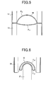
- Fig. 3 shows a relationship between a discharge rate of high-pressure water and a discharge pressure, wherein air is supplied at a pressure of 0.6 MPa to a hydraulic pump with an air/water area ratio of 65/1. It is noted from the relationship that the inflow rate of the high-pressure water is gradually reduced as an increase of an internal pressure of a rockbolt and finally to 10.6 liters/minute at an internal pressure of 7 MPa.
- the shaped pipe of 2mm in thickness starts expansion at a pressure of 7 MPa, but the shaped pipe of 3 mm in thickness does not start expansion at a pressure of 7 MPa. Expansion of the thicker shaped pipe is initiated, when the internal pressure reaches 17 MPa. A discharge rate of the high-pressure water is reduced to 7.2 litters/min at the internal pressure of 17 MPa.
- the expansive deformation of the shaped pipe continues at a pressure lower than the expansion-initiating pressure, and the expansion mode is substantially constant nevertheless thickness of the shaped pipe.
- an additional pressure is further applied to the expanded rockbolt so as to press the expansively deformed pipe onto an inner wall of the rockbolt-setting hole.
- the thinner shaped pipe is expansively deformed by an internal pressure of 7 MPa
- the internal pressure is necessarily raised to 17 MPa for the expansive deformation of the thicker shaped pipe.
- Injection of high-pressure water shall be continued at a discharge rate corresponding to a discharge pressure of 7-17 MPa.
- a hydraulic pump shall be compensatorily driven for a longer time.
- a pressure for further expansive deformation is higher compared with the thinner shaped pipe, so that it is obliged to inject high-pressure water in a higher discharge pressure region, in other words a small discharge rate region, for continuation of the expansive deformation of the thicker shaped pipe.
- a time period for hydraulic expansion of the thicker shaped pipe is longer than that for the thinner shaped pipe.
- the completion of expansive deformation in a short time is also the advantage originated in the thinner rockbolt made of high-strength steel.
- the inventive rockbolts are manufactured from high-strength steel sheets by the following steps:
- a high-strength steel sheet of 1.8-2.3 mm in thickness with predetermined mechanical properties is processed to a welded pipe having an outer diameter of 50-55 mm by a conventional pipe-making process using high frequency welding, laser welding, TIG welding or the like.
- the welded pipe is roll-formed to a shaped pipe having an outer diameter of 34-38 mm and a dented sectional profile defined by a circumferential part and a concavity.
- a roll-forming process proposed by JP 2003-145216 A , is suitable for forming the welded pipe to the shaped pipe. But, an extrusion or press-forming process may be also employed, instead of the roll-forming.
- a sectional profile of a welded pipe is reformed step by step, as shown in Fig. 4.
- a welded pipe with a circular profile (Fig. 4a) is prepared by a high frequency welding method or the like.
- the welded pipe is roll-formed to a sectional profile C 1 (Fig. 4b) comprising a convex surface F 11 with a large radius of curvature and another convex surface F 21 with a small radius of curvature.
- the convex surface F 11 has a circumferential length corresponding to a circumferential length of a part of an objective shaped pipe including a concavity 4.
- the other convex surface F 21 has a circumferential length corresponding to a circumferential length of the other part of the objective shaped pipe.
- These convex surfaces F 11 and F 21 are formed by a rolling stand equipped with a couple of forming rolls 11 and 12 having concave profiles with a radius of curvature different from each other, as shown in Fig. 5.
- a multi-stage rolling stand may be also employed for successively changing radii of curvatures of the convex surfaces F 11 and F 21 .
- Concave profiles of the forming rolls 11 and 12 are transcribed to the welded pipe M, by passing the welded pipe M through a gap between the forming rolls 11 and 12. That is, a circular profile C 0 (Fig. 4a) is reformed to a sectional profile C 1 (Fig. 4b) comprising the convex surface F 11 with a large radius of curvature and the convex surface F 21 with a small radius of curvature.
- a disc roll 21 (Fig. 6) having an edge with a small radius of curvature is pressed onto a center of the convex surface F 11 , so as to dent the convex surface F 11 inwards, as shown in Fig. 4c.
- a rolling stand in the second roll-forming step is equipped with a forming roll 22, which has a concave profile with a radius of curvature smaller than the concave profile of the forming roll 12 in the first roll-forming step, in addition to the disc roll 21, as shown in Fig. 6.
- a multi-stage rolling stand may be also employed for making radii of curvatures successively smaller.
- a rolling stand in this step is equipped with a couple of forming rolls 31 and 32 having concave profiles with a radius of curvature smaller than the initial diameter of the welded pipe M, as shown in Fig. 7.
- a multi-stage rolling stand may be also used for making the radius of curvature successively smaller in the third roll-forming step.
- the convex surface F 22 is curved to a circular profile F 23 with a small radius of curvature so as to narrow an opening (o) in correspondence to concave profiles of the rolls 31 and 32, as shown in Fig. 4d.
- the guttered concavity part F 12 is also reformed to a small diameter concavity part F 13 .
- the welded pipe M is preferably rotated by 90 degrees around its axis from a positional relationship with the rolls 11 and 12 in the first step or with the rolls 21 and 22 in the second step to such a position that the opening (o) and the weld bead (w) are disposed between the rolls 31 and 32. Due to the 90 degree rotation, a forming pressure is uniformly applied from the rolls 31 and 32 to the convex surface F 22 , so that the sectional profile C 2 is reformed to a circular profile C 3 comprising an inner part F 13 and a circumferential part F 23 , both of which have uniform radii of curvature, as shown in Fig. 4d.
- the sectional profile C 3 with a narrowed opening (o) is dressed to a circular profile C 4 having an outer diameter smaller than an inner diameter of a rockbolt-setting hole in a bedrock or ground, in the fourth roll-forming step.
- a rolling stand in this step preferably has a pressing roll 43 in addition to a couple of forming rolls 41 and 42, as shown in Fig. 8.
- a multi-stage rolling stand may be also used for successively reforming the sectional profile C 3 to the small diameter profile C 4 .
- the welded pipe M is stationarily held at a predetermined positional relationship during roll-forming, so as to ensure uniform reformation of the convex surface F 22 until a quasi-double sectional profile C 4 is formed by the outer periphery F 24 and the inner periphery F 14 with the opening (o) being nearly closed.
- escape of the circumferential part F 23 from the gap is inhibited by the pressing roll 43, so that the welded pipe M is formed to an objective small diameter profile C 4 without flattening.
- the shaped pipe with the objective profile C 4 is sized to a predetermined length and sealed at both ends.
- a front end of the shaped pipe is sealed as follows:
- a part of 80 mm in longitudinal length from the front end is swaged to a size of 32-34 mm in outer diameter.
- a sleeve of 36-40 mm in outer diameter, 2.0-3.0 mm in thickness and 60-80 mm in length is fixed to the swaged end part.
- a punch is pressed into an open end of the shaped pipe so as to reform the end part to a flat shape corresponding to a collet of the punch, and the pressed end part is sealed by welding.
- the opposite end of the shaped pipe is designed for introduction of a pressurized fluid and sealed as follows:
- a part of 80 mm in longitudinal length from the opposite end is swaged in the same way.
- a sleeve of 40-42 mm in outer diameter, 3.5-4.5 mm in thickness and 60-80 mm in length is fixed to the swaged end part.
- a punch is pressed into an open end of the shaped pipe so to reform the end part to a flat shape corresponding to a collet of the punch, and the pressed end part is sealed by welding.
- the sleeve preferably has a circumferential groove for firmly chucking a rockbolt embedded in a bedrock or ground for pullout test.
- a hole for introduction of a pressurized fluid into the interior of the shaped pipe is formed by drilling the sleeve at the opposite end. A position of the hole is determined at a part slightly apart from the end of the sleeve.
- coated steel pipes which have plating layers formed on inner and outer surfaces, are appropriate material for corrosion-resistant and durable rockbolts in the bedrock or ground.
- Such coated steel pipes are offered by a pre-coating or post-coating process, but pre-coated steel pipes, which are manufactured from coated steel sheets, are profitable in respect to productivity.
- a plating layer may be Zn, Zn-Al or Zn-Al-Mg.
- a Zn plating layer is preferably formed on a steel base by immersing a steel strip in molten zinc containing 0.1-0.2% of Al, which suppresses growth of a Fe-Zn alloy layer harmful on workability.
- a Zn-Al plating layer e.g. Zn-5% Al or Zn-55% Al, exhibits corrosion-resistance 2-4 times better than a Zn plating layer of the same thickness.
- a Zn-Al-Mg plating layer is hard and exhibits the optimum corrosion-resistance, so that a rockbolt coated with the hard Zn-Al-Mg plating layer is placed and expanded in a bedrock or ground without scratches caused by abrasion with the bedrock or collision of scatters. Scratching is also inhibited during handling or transporting the coated rockbolt. Since scratches, which act as starting points of corrosion, are scarcely formed, the embedded rockbolt maintains good durability and reliability in addition to the excellent corrosion-resistant even in a corrosive environment.
- the Zn-Al-Mg plating layer may be thinned to 3-30 ⁇ m due to excellent corrosion-resistance and hardness.
- the Zn-Al-Mg plating layer contains 0.05-10% Mg, 4-22% Al. It may further contain 0.001-0.1% Ti, 0.0005-0.045% B and/or 0.005-2.0% at least one selected from the group consisting of rare earth metals, Y, Zr and Si.
- An element Mg is incorporated in a zincic corrosion product, which is formed on a surface of the plating layer.
- the Mg -containing zincic corrosion product together with an element Al in the plating layer reduces a corrosion rate of the plating layer in a soil environment. Since a part of the Mg- containing zincic corrosion product also flows into a weld bead and a cut edge in a process of manufacturing a pre-coated steel pipe, the weld bead and the cut edge are also prevented from corrosion. Moreover, when a welded part is repaired by thermal spraying, the Mg -containing zincic corrosion product flows onto a sprayed layer or into a corrosion product on the sprayed layer, resulting in protection of a steel base from corrosion. Mg is also important for hardening the plating layer by formation of a Zn-Mg intermetallic compound. These effects are achieved by controlling a Mg content within a range of 0.05-10% (preferably 1-4%).
- the other element Al is converted to a clinging Zn-Al corrosion product effective as a corrosion inhibitor.
- Zn/Al/Zn 2 Mg ternary eutectic grains appear in a solidified plating layer due to presence of Al.
- the ternary eutectic grains have a microstructure finer than Zn/Zn 2 Mg binary eutectic grains and raise hardness of the plating layer.
- An Al content of 4% or more is necessary for formation of the clinging Zn-Al corrosion product and the Zn/Al/Zn 2 Mg ternary eutectic grains.
- an increase of the Al content raises a melting temperature of a plating metal and needs holding a hot-dip bath at an elevated temperature, resulting in poor productivity. In this sense, an upper limit of the Al content is determined at 22%.
- Optional elements Ti and B impedes formation of a Zn 11 Mg 2 phase harmful on an external appearance of a coated steel sheet, so that Zn-Mg intermetallic precipitates present in a plating layer are substantially composed of Zn 2 Mg.
- the effect of Ti on inhibiting formation of the Zn 11 Mg 2 phase is apparently noted by 0.001% or more (preferably 0.002% or more) of Ti.
- excess Ti above 0.1% promotes growth of a Ti-Al precipitate, resulting in a rugged surface of the plating layer with poor external appearance.
- Formation of the Zn 11 Mg 2 phase is also impeded by addition of B at a ratio of 0.0005% or more (preferably 0.001% or more). But, excess B above 0.045% promotes growth of Ti-B and Al-B intermetallic compounds, which degrade a smooth surface and external appearance of a plating layer.
- a rockbolt which is prepared from a steel pipe hot-dip coated with a Zn-Al-Mg plating layer containing Al and Mg at relatively large ratios, often reduces its surface gloss.
- a surface of the plating layer is changed from a fine metallic luster to gray with the lapse of time.
- the rockbolt decreases its commercial value.
- Reduction of the surface gloss is prevented by adding at least one oxidizable element selected from the group consisting of rare earth metals, Y, Zr and Si at a ratio of 0.005% or more.
- a maximum ratio of the oxidizable element is determined at 2.0%, since its effect on reduction of the surface gloss can not be expected any more by excess addition above 2.0%.
- a Fe-Al intermetallic compound, harmful on workability and formability of the coated steel sheet or pipe, is more formed as an increase of Al in the Zn-Al-Mg plating layer.
- the Fe-Al intermetallic compound at a boundary between a base steel and a plating layer unfavorably causes peeling-off of the plating layer during working or forming a coated steel sheet or pipe. Formation of the intermetallic compound is inhibited by inclusion of Si at a small ratio in the plating layer.
- a high-strength steel sheet of 2.1 mm in thickness with tensile strength of 490 N/mm 2 and elongation of 28% was processed to a welded pipe of 54 mm in outer diameter.
- the welded pipe was roll-formed to a shaped pipe of 36 mm in outer diameter with a sectional profile, as shown in Fig. 2A, having a concavity 4 extending along an axial direction.
- the shaped pipe had tensile strength of 550 N/mm 2 .
- the shaped pipe was sized to a length of 4 m. End parts in longitudinal length of 75 mm from edges of the sized pipe were swaged to a profile of 33.1 mm in outer diameter. A sleeve of 33.1 mm in inner diameter, 38.1 mm in outer diameter, 2.5 mm in thickness and 70 mm in length was fixed to one end part, and the end part was sealed with the sleeve by welding. Another sleeve of 33.1 mm in inner diameter, 41.1 mm in outer diameter, 4.0 mm in thickness and 70 mm in length was fixed to the opposite end part at a side for introduction of a pressurized fluid, and the end part was sealed with the sleeve by welding.
- a rockbolt was manufactured from a steel sheet of 3.0 mm in thickness with tensile strength of 300 N/mm 2 and elongation of 35% by processing the steel sheet to a welded pipe of 54 mm in outer diameter and then roll-forming the welded pipe to a shaped pipe of 36 mm in outer diameter under the same conditions.
- a seal head for hydraulic expansion was attached to each of the inventive and comparative rockbolts, and high-pressure water was injected into an interior of the shaped pipe by a hydraulic pump.
- the shaped pipe was hydraulically expanded. Expansive deformation was investigated in detail.
- the inventive rockbolt started expansive deformation, i.e. bulging of the concavity 4 (Fig. 2A), when a hydraulic pressure in the shaped pipe reached 7 MPa. Once the expansive deformation occurred, it continued at a hydraulic pressure of 5 MPa. During propagation of the expansive deformation, high-pressure water was injected into the shaped pipe at a flow rate of 11.3 litters/minute, and the expansive deformation was completed in 31 seconds.
- the concavity 4 of the comparative rockbolt did not expansively reverse at a hydraulic pressure of 7 MPa, but the expansive deformation started when the hydraulic pressure reached 17 MPa.
- a hydraulic pressure necessary for continuation of the expansive deformation was 10 MPa.
- a feed rate of the high-pressure water at the hydraulic pressure of 10 MPa was only 9.6 litters/minute, and 41 seconds were spent for completion of the expansive deformation.
- Rockbolts which were hydraulically expanded with an assumption of placement in a construction site, were subjected to pullout test. Test results prove that the inventive rockbolts had strength of about 170 kN. Since the inventive rockbolts were thinned and lightened by about 30% compared with conventional rockbolts, transportation to or handling in a construction site becomes easy. Furthermore, shaped pipes, which are prepared from welded pipes with less accumulation of strains, are expansively deformed to objective profiles without bursting caused by introduction of strains during hydraulic expansion, resulting in safety of rock bolting works.
Landscapes
- Engineering & Computer Science (AREA)
- Mining & Mineral Resources (AREA)
- Structural Engineering (AREA)
- Life Sciences & Earth Sciences (AREA)
- General Life Sciences & Earth Sciences (AREA)
- Geochemistry & Mineralogy (AREA)
- Geology (AREA)
- Chemical & Material Sciences (AREA)
- Chemical Kinetics & Catalysis (AREA)
- Materials Engineering (AREA)
- Mechanical Engineering (AREA)
- Metallurgy (AREA)
- Organic Chemistry (AREA)
- Earth Drilling (AREA)
- Piles And Underground Anchors (AREA)
- Excavating Of Shafts Or Tunnels (AREA)
- Shaping Metal By Deep-Drawing, Or The Like (AREA)
Abstract
Description
- The present invention relates to a high-strength steel pipe rockbolt, which is firmly fixed to a bedrock or ground in a state radially expanded by a hydraulic pressure, and a method of manufacturing thereof.
- A steel pipe rockbolt, which is firmly fixed to a bedrock or ground in an expanded state, is manufactured from a hollow shaped pipe having one or more expansive concavities extending an axial direction. The
steel pipe rockbolt 1 has a sealed end, which is inserted into a rockbolt-setting hole formed in a bedrock orground 2, as shown in Fig. 1. There is a vacancy between the rockbolt-setting hole and the un-expanded steel pipe rockbolt 1 (Fig. 2A). Thesteel pipe rockbolt 1 is expanded by a hydraulic pressure (Fig. 2B), and finally pressed onto an inner wall of the rockbolt-setting hole (Fig. 2C). Consequently, the bedrock orground 2 is reinforced with therockbolt 1. - A shaped pipe with at least an
expansive concavity 4, which extends along an axial direction, has been used as an expansive rockbolt, in order to facilitate expansion by a hydraulic pressure. The shaped pipe has hermetically sealed top and rear ends and a hole for introduction of a pressurized fluid at its side wall. A shaped steel pipe, which has sleeves fixed to its both ends for introduction of a pressurized fluid, is also disclosed inJP 2003-501573 A - For standardization of labors and saving of labor costs in construction sites such as tunnels, many rockbolt-setting holes of the same size are drilled in a bedrock or
ground 2, and steel pipe rockbolts of the same diameter are placed in the rockbolt-setting holes. For instance, a shaped pipe, which is formed from a steel pipe of 54 mm in outer diameter to a profile having an outer diameter of 36 mm and aconcavity 4, is placed in a rockbolt-setting hole of 45-50 mm in size and firmly fixed to a bedrock orground 2 by hydraulic expansion. - The expansive steel pipe rockbolts are classified to a 110 kN group and a 170 kN group by yield strength necessary for construction conditions, e.g. competence and geomechanics of a bedrock or ground as well as cross-sectional profiles of tunnels. Rockbolts, which belong to the 110 kN group, are manufactured from steel sheets of 2 mm in thickness with tensile strength of 300 N/mm2 or more and total elongation of 30% or more. Rockbolts, which belong to the 170 kN group, are manufactured from steel sheets of 3 mm in thickness with tensile strength of 300 N/mm2 or more and total elongation of 35% or more. In any case, the steel sheet is formed to a cylindrical pipe of 54 mm in outer diameter and further reformed to a shaped pipe of 36 mm in outer diameter with a
concavity 4. - The shaped pipe is manufactured by partially bending a cylindrical pipe with a small bending radius in a sectional plane, as shown in Fig. 2A. On the presumption that shaped pipes have the same outer diameter, a bending radius at a center is smaller as a thickness increase of a steel sheet, which is formed to a shaped pipe. The shaped pipes are further swaged at its both ends, since sleeves having inner and outer diameters regularized in size are fixed to the end parts of the shaped pipes. A thicker steel sheet is reformed with a smaller bending radius even in the swaging process. That is, a local bending radius becomes smaller as an thickness increase of a steel sheet for raising strength of a rockbolt.
- By the way, many strains are introduced into a steel sheet in a pipe-making process, a pipe-shaping process and a swaging process. Strains are also accumulated during hydraulic expansion of a shaped pipe. When the shaped pipe is further expanded, it is often cracked due to introduction of additional strains. Cracking causes leakage of a pressurized fluid, insufficient expansion of the shaped pipe and shortage of strength necessary for a rockbolt.
- The present invention aims at provision of high-strength steel pipe rockbolts with high reliability. An object of the invention is to inhibit cracking of rockbolts, which are induced by strains introduced in a pipe-shaping process, a swaging process and a hydraulically expanding process. Another object of the invention is to initiate expansive deformation of the shaped pipe at a relatively lower pressure during hydraulic expansion and to complete the expansive deformation in a short time period.
- The invention proposes a high-strength steel pipe rockbolt, comprising an expansive rockbolt main body formed from a shaped pipe having one or more concavities extending along an axial direction. The shaped pipe is manufactured from a high-strength steel sheet of 1.8-2.3 mm in thickness with tensile strength of 490-640 N/mm2 and elongation of 20% or more. The shaped pipe preferably has tensile strength of 530-690 N/mm2 and elongation of 20% or more.
- The material of the rockbolt may be a high-strength steel sheet coated with a Zn, Zn-Al or Zn-Al-Mg plating layer. The plating layer is present on a surface of the shaped pipe after being roll-formed and protects a rockbolt, which is embedded in a bedrock or ground, from a corrosive atmosphere.
- The inventive steel pipe rockbolt is manufactured by the following steps:
- (1) A step of forming a high-strength steel sheet of 1.8-2.3 mm in thickness with tensile strength of 490-640 N/mm2 and elongation of 20% or more to a welded steel pipe of 50-55 mm in outer diameter.
- (2) A step of roll-forming the welded steel pipe to a shaped pipe having an outer diameter of 34.0-38.0 mm and one or more concavities extending along an axial direction.
- (3) A step of cutting the shaped pipe to a predetermined length.
- (4) A step of swaging both ends of the cut shaped pipe.
- (5) A step of sealing both ends (i.e. one end of the shaped pipe to be placed in a rockbolt-setting hole and the other end for introduction of a pressurized fluid) of the shaped pipe with sleeves.
- (6) A step of forming a hole, which extends to an interior of the shaped pipe for introduction of a pressurized fluid, at a side wall of the sleeve.
-
- Fig. 1 is an explanatory view for reinforcement of a ground with an expanded rockbolt.
- Fig. 2A is a sectional view illustrating a rockbolt, which is placed in a rockbolt-setting hole of a ground but not expanded yet.
- Fig. 2B is an explanatory view for application of a hydraulic pressure to a rockbolt during expansion.
- Fig. 2C is an explanatory view for application of a pressure to a rockbolt, which is completely expanded.
- Fig. 3 is a graph showing performance of a hydraulic pump.
- Fig. 4 is an explanatory view showing changes of a sectional profile of a pipe in response to shaping steps.
- Fig. 5 is a schematic view illustrating profiles of forming rolls, which are used at a first step of a pipe-shaping process.
- Fig. 6 is a schematic view illustrating profiles of forming rolls, which are used at a second step of a pipe-shaping process.
- Fig. 7 is a schematic view illustrating profiles of forming rolls, which are used at a third step of a pipe-shaping process.
- Fig. 8 is a schematic view illustrating profiles of forming rolls, which are used at a forth step of a pipe-shaping process.
- The inventive steel pipe rockbolt is manufactured from high-strength steel. Selection of the high-strength steel enables use of a thin steel sheet as material of the rockbolt. When a rockbolt formed from a thinner steel sheet is compared with a conventional rockbolt on the presumption that the rockbolts have the same outer diameter, a minimum bending radius of a curved part, which defines an axially extending concavity, is larger at a center along a radial direction. Strains, which are introduced into a steel pipe in a pipe-shaping process and hydraulic expansion of a shaped pipe, are reduced in a total amount as a decrease of thickness of the steel sheet. Due to reduction of the strains, the shaped pipe is hydraulically expanded without cracking. Use of the thinner steel sheet also means lightening of the rockbolt. Consequently, the inventive rockbolt is good of handlability and workability with high reliability.
- Expansion of a concavity of the shaped pipe is initiated at a lower hydraulic pressure, as a rockbolt is thinner. Deformation of the shaped pipe continues at a lower hydraulic pressure even after initiation of expansion, so that a large volume of a pressurized fluid can be introduced into the shaped pipe without raising a load of a high-pressure pump. Consequently, hydraulic expansion is completed in a short time. In this respect, use of the thinner steel sheet as material of the rockbolt is advantageous for remarkable improvement of work efficiency.
- For instance, a shaped pipe with tensile strength of 400 N/mm2, which has been used for a rockbolt with yield strength of 170 kN, is manufactured by forming a steel sheet of 3 mm in thickness with tensile strength of about 300 N/mm2 and elongation of about 35% to a welded steel pipe of 54 mm in outer diameter and reforming the welded pipe to a shaped pipe of 36 mm in outer diameter.
- When a thin high-strength steel sheet is used as material for a 170 kN-class rockbolt, a strong and reliable rockbolt, which is hydraulically expanded without cracking, is obtained. In fact, a shaped pipe, which is manufactured by forming a high-strength steel sheet of 1.8-2.3 mm in thickness with tensile strength of 490-640 N/mm2 and elongation of 20% or more to a welded pipe of 54 mm in outer diameter and then shaping the welded pipe to an objective profile of 36 mm in outer diameter, has tensile strength of 530-690 N/mm2. Consequently, a rockbolt, which is formed from the high-strength shaped pipe, is firmly fixed to a bedrock or ground with strength of about 170 kN, by placing it in a rockbolt-setting hole of the bedrock or ground and hydraulically expanding it therein.
- Use of a thinner steel sheet enables bending a surface part of a welded pipe with a larger bending radius in a pipe-shaping process. Presume that a cylindrical pipe of 54 mm in outer diameter is formed to a shaped pipe with a cross section shown in Fig. 2A, wherein a curved part (a concavity 4) has an outside bending radius of 5 mm. A shaped pipe, which is formed from a cylindrical pipe of 3 mm in thickness, has a curved part with an inside bending radius of 2 mm. On the other hand, a shaped pipe, which is formed from a cylindrical pipe of 2 mm in thickness, has a curved part with an inside bending radius of 3 mm. In short, as a decrease in thickness of a welded pipe (in other words, a steel sheet), a bending radius becomes larger, resulting in reduction of cumulative strains during pipe-shaping. Reduction of the cumulative strains means an increase of a tolerance limit until the shaped pipe is cracked due to accumulation of strains. Consequently, the inventive rockbolt is hydraulically expanded in a bedrock or ground without fears of bursting.
- A thickness of a steel sheet is determined within a range of 1.8-2.3 mm in order to effectively reduce accumulation of strains. If the thickness exceeds 2.3 mm, it is difficult to realize an increase of a bending radius in a pipe-shaping process. On the other hand, the thickness less than 1.8 mm means necessity of a high-strength steel sheet with tensile strength of 640 N/mm2 or more, otherwise strength of 170 kN or so would not be imparted to a rockbolt. However, such high-strength steel sheets can not be formed to an objective profile due to poor elongation in a pipe-shaping process, and shaped pipes useful as expansive rockbolts can not be manufactured with ease from welded steel pipes of 50-55 mm in outer diameter. Besides, steel sheets shall have tensile strength of 490 N/mm2 or more; otherwise rockbolts with 170 kN or so would not be manufactured from welded pipes of 50-55 mm in outer diameter. Elongation of 20% or more is also necessary, in order to hydraulic expand shaped pipes without bursting.
- The expansive steel pipe rockbolt has a shaped pipe with a cross section, as shown in Fig. 2A. At least one
concavity 4 extends along an axial direction of the shaped pipe. When a pressurized fluid is introduced into the shaped pipe, the shaped pipe is expansively returned to its original cylindrical profile by bulging of theconcavity 4. On the presumption that shaped pipes have the same outer diameter and the same profile of theconcavity 4, a larger pressure is necessary for bulging theconcavity 4 as an increase in thickness of the shaped pipe. The thickness effect of the shaped pipe on bulging of theconcavity 4 is explained as follows: A moment for rebending a dented steel sheet to its original profile with hydraulic expansion is roughly estimated according to a formula of (t 2 b/4) X σ e (wherein t is thickness, b is width, and σ e is yield stress of the steel sheet), and the moment increases at a ratio in proportion to square thickness t 2 . - In the case where an internal pressure of a vessel is raised to a predetermined value by introduction of a pressurized fluid into the vessel from a hydraulic pump, a large amount of the pressurized fluid flows from the pump into the vessel at a relatively lower inner pressure, but the flow rate is gradually reduced as an increase of the internal pressure. Accounting the relationship of the internal pressure with the flow rate, initiation of bulging of the
concavity 4 at a lower pressure means inflow of a large amount of the pressurized fluid into the shaped pipe at a low-pressure stage until expansion of the shaped pipe. If expansion of the shaped pipe is initiated at a higher pressure on the contrary, an inflow rate of the pressurized fluid gradually decreases in correspondence with an increase of the internal pressure of the shaped pipe. In this case, it is unavoidable to continue introduction of the pressurized fluid for a long time until the internal pressure is raised to a value necessary for initiation of expansion. - In fact, Fig. 3 shows a relationship between a discharge rate of high-pressure water and a discharge pressure, wherein air is supplied at a pressure of 0.6 MPa to a hydraulic pump with an air/water area ratio of 65/1. It is noted from the relationship that the inflow rate of the high-pressure water is gradually reduced as an increase of an internal pressure of a rockbolt and finally to 10.6 liters/minute at an internal pressure of 7 MPa.
- Presume that a pressure of 7 MPa is necessary for initiation of bulging of the
concavity 4, which is formed at a shaped pipe of 2 mm in thickness and that a pressure of 17 MPa is necessary for initiation of bulging of theconcavity 4, which is formed at a shaped pipe of 3 mm in thickness. When a rockbolts is hydraulically expanded with a supply air pressure of 0.6 MPa under the above conditions, an inflow rate of the high pressure water is varied in correspondence with an internal pressure of the rockbolt as follows: - The shaped pipe of 2mm in thickness starts expansion at a pressure of 7 MPa, but the shaped pipe of 3 mm in thickness does not start expansion at a pressure of 7 MPa. Expansion of the thicker shaped pipe is initiated, when the internal pressure reaches 17 MPa. A discharge rate of the high-pressure water is reduced to 7.2 litters/min at the internal pressure of 17 MPa.
- Once the bulging of the
concavity 4 starts, the expansive deformation of the shaped pipe continues at a pressure lower than the expansion-initiating pressure, and the expansion mode is substantially constant nevertheless thickness of the shaped pipe. After the shaped pipe is expanded to a size corresponding to an inner diameter of a rockbolt-setting hole in a bedrock or ground, an additional pressure is further applied to the expanded rockbolt so as to press the expansively deformed pipe onto an inner wall of the rockbolt-setting hole. - Although the thinner shaped pipe is expansively deformed by an internal pressure of 7 MPa, the internal pressure is necessarily raised to 17 MPa for the expansive deformation of the thicker shaped pipe. Injection of high-pressure water shall be continued at a discharge rate corresponding to a discharge pressure of 7-17 MPa. As a result, a hydraulic pump shall be compensatorily driven for a longer time. Moreover, a pressure for further expansive deformation is higher compared with the thinner shaped pipe, so that it is obliged to inject high-pressure water in a higher discharge pressure region, in other words a small discharge rate region, for continuation of the expansive deformation of the thicker shaped pipe. In short, a time period for hydraulic expansion of the thicker shaped pipe is longer than that for the thinner shaped pipe. The completion of expansive deformation in a short time is also the advantage originated in the thinner rockbolt made of high-strength steel.
- The inventive rockbolts are manufactured from high-strength steel sheets by the following steps:
- A high-strength steel sheet of 1.8-2.3 mm in thickness with predetermined mechanical properties is processed to a welded pipe having an outer diameter of 50-55 mm by a conventional pipe-making process using high frequency welding, laser welding, TIG welding or the like. The welded pipe is roll-formed to a shaped pipe having an outer diameter of 34-38 mm and a dented sectional profile defined by a circumferential part and a concavity.
- A roll-forming process, proposed by
JP 2003-145216 A - According to the roll-forming process, a sectional profile of a welded pipe is reformed step by step, as shown in Fig. 4.
- At first, a welded pipe with a circular profile (Fig. 4a) is prepared by a high frequency welding method or the like.
- The welded pipe is roll-formed to a sectional profile C1 (Fig. 4b) comprising a convex surface F 11 with a large radius of curvature and another convex surface F21 with a small radius of curvature. The convex surface F 11 has a circumferential length corresponding to a circumferential length of a part of an objective shaped pipe including a
concavity 4. The other convex surface F 21 has a circumferential length corresponding to a circumferential length of the other part of the objective shaped pipe. These convex surfaces F 11 and F 21 are formed by a rolling stand equipped with a couple of formingrolls - Concave profiles of the forming rolls 11 and 12 are transcribed to the welded pipe M, by passing the welded pipe M through a gap between the forming rolls 11 and 12. That is, a circular profile C0 (Fig. 4a) is reformed to a sectional profile C1 (Fig. 4b) comprising the convex surface F11 with a large radius of curvature and the convex surface F 21 with a small radius of curvature.
- In the second roll-forming step, a disc roll 21 (Fig. 6) having an edge with a small radius of curvature is pressed onto a center of the convex surface F11, so as to dent the convex surface F11 inwards, as shown in Fig. 4c. A rolling stand in the second roll-forming step is equipped with a forming
roll 22, which has a concave profile with a radius of curvature smaller than the concave profile of the formingroll 12 in the first roll-forming step, in addition to the disc roll 21, as shown in Fig. 6. A multi-stage rolling stand may be also employed for making radii of curvatures successively smaller. - When the welded pipe M is passed though a gap between the disc roll 21 and the
concave roll 22 in the manner that the disc roll 21 is pressed onto a center of the convex surface F11, the center of the convex surface F11 is dented inwards, so that the welded pipe M is reformed to a sectional profile C2 (Fig. 4c) having a guttered curved part F12 extending along an axial direction. The other curved part F22, which defines an external profile of a shaped pipe, keeps an initial radius of curvature of the welded pipe M. - Since an expansively deformed pipe is pressed onto an inner wall of a rockbolt-setting hole in a bedrock or ground for reinforcement, the inner diameter of the rockbolt-setting hole is larger than an outer diameter of a shaped pipe but smaller than an outer diameter of the welded pipe M. Therefore, the sectional profile C2 is reformed to a small diameter profile C3 in the third roll-forming step. A rolling stand in this step is equipped with a couple of forming
rolls - When the pipe with the sectional profile C2 is passed through a gap between the
rolls rolls rolls rolls 21 and 22 in the second step to such a position that the opening (o) and the weld bead (w) are disposed between therolls rolls - The sectional profile C3 with a narrowed opening (o) is dressed to a circular profile C4 having an outer diameter smaller than an inner diameter of a rockbolt-setting hole in a bedrock or ground, in the fourth roll-forming step. A rolling stand in this step preferably has a
pressing roll 43 in addition to a couple of formingrolls - When a forming pressure is applied from the
rolls roll 43 is pressed onto the center of the circumferential part F22, the welded pipe M is stationarily held at a predetermined positional relationship during roll-forming, so as to ensure uniform reformation of the convex surface F22 until a quasi-double sectional profile C4 is formed by the outer periphery F24 and the inner periphery F14 with the opening (o) being nearly closed. During roll-forming, escape of the circumferential part F23 from the gap is inhibited by thepressing roll 43, so that the welded pipe M is formed to an objective small diameter profile C4 without flattening. - The shaped pipe with the objective profile C4 is sized to a predetermined length and sealed at both ends.
- A front end of the shaped pipe is sealed as follows:
- A part of 80 mm in longitudinal length from the front end is swaged to a size of 32-34 mm in outer diameter. A sleeve of 36-40 mm in outer diameter, 2.0-3.0 mm in thickness and 60-80 mm in length is fixed to the swaged end part. A punch is pressed into an open end of the shaped pipe so as to reform the end part to a flat shape corresponding to a collet of the punch, and the pressed end part is sealed by welding.
- The opposite end of the shaped pipe is designed for introduction of a pressurized fluid and sealed as follows:
- A part of 80 mm in longitudinal length from the opposite end is swaged in the same way. A sleeve of 40-42 mm in outer diameter, 3.5-4.5 mm in thickness and 60-80 mm in length is fixed to the swaged end part. A punch is pressed into an open end of the shaped pipe so to reform the end part to a flat shape corresponding to a collet of the punch, and the pressed end part is sealed by welding. The sleeve preferably has a circumferential groove for firmly chucking a rockbolt embedded in a bedrock or ground for pullout test.
- After both ends are sealed, a hole for introduction of a pressurized fluid into the interior of the shaped pipe is formed by drilling the sleeve at the opposite end. A position of the hole is determined at a part slightly apart from the end of the sleeve.
- Rockbolts embedded in a bedrock or ground are exposed to corrosive atmospheres of from acid to alkali in response to humidity, water quality, ventilation and so on. Accounting the atmospheres, coated steel pipes, which have plating layers formed on inner and outer surfaces, are appropriate material for corrosion-resistant and durable rockbolts in the bedrock or ground. Such coated steel pipes are offered by a pre-coating or post-coating process, but pre-coated steel pipes, which are manufactured from coated steel sheets, are profitable in respect to productivity.
- A plating layer may be Zn, Zn-Al or Zn-Al-Mg. A Zn plating layer is preferably formed on a steel base by immersing a steel strip in molten zinc containing 0.1-0.2% of Al, which suppresses growth of a Fe-Zn alloy layer harmful on workability. A Zn-Al plating layer, e.g. Zn-5% Al or Zn-55% Al, exhibits corrosion-resistance 2-4 times better than a Zn plating layer of the same thickness. A Zn-Al-Mg plating layer is hard and exhibits the optimum corrosion-resistance, so that a rockbolt coated with the hard Zn-Al-Mg plating layer is placed and expanded in a bedrock or ground without scratches caused by abrasion with the bedrock or collision of scatters. Scratching is also inhibited during handling or transporting the coated rockbolt. Since scratches, which act as starting points of corrosion, are scarcely formed, the embedded rockbolt maintains good durability and reliability in addition to the excellent corrosion-resistant even in a corrosive environment.
- The Zn-Al-Mg plating layer may be thinned to 3-30µm due to excellent corrosion-resistance and hardness. The Zn-Al-Mg plating layer contains 0.05-10% Mg, 4-22% Al. It may further contain 0.001-0.1% Ti, 0.0005-0.045% B and/or 0.005-2.0% at least one selected from the group consisting of rare earth metals, Y, Zr and Si.
- An element Mg is incorporated in a zincic corrosion product, which is formed on a surface of the plating layer. The Mg-containing zincic corrosion product together with an element Al in the plating layer reduces a corrosion rate of the plating layer in a soil environment. Since a part of the Mg-containing zincic corrosion product also flows into a weld bead and a cut edge in a process of manufacturing a pre-coated steel pipe, the weld bead and the cut edge are also prevented from corrosion. Moreover, when a welded part is repaired by thermal spraying, the Mg-containing zincic corrosion product flows onto a sprayed layer or into a corrosion product on the sprayed layer, resulting in protection of a steel base from corrosion. Mg is also important for hardening the plating layer by formation of a Zn-Mg intermetallic compound. These effects are achieved by controlling a Mg content within a range of 0.05-10% (preferably 1-4%).
- The other element Al is converted to a clinging Zn-Al corrosion product effective as a corrosion inhibitor. Zn/Al/Zn2Mg ternary eutectic grains appear in a solidified plating layer due to presence of Al. The ternary eutectic grains have a microstructure finer than Zn/Zn2Mg binary eutectic grains and raise hardness of the plating layer. An Al content of 4% or more is necessary for formation of the clinging Zn-Al corrosion product and the Zn/Al/Zn2Mg ternary eutectic grains. However, an increase of the Al content raises a melting temperature of a plating metal and needs holding a hot-dip bath at an elevated temperature, resulting in poor productivity. In this sense, an upper limit of the Al content is determined at 22%.
- Optional elements Ti and B impedes formation of a Zn11Mg2 phase harmful on an external appearance of a coated steel sheet, so that Zn-Mg intermetallic precipitates present in a plating layer are substantially composed of Zn2Mg. The effect of Ti on inhibiting formation of the Zn11Mg2 phase is apparently noted by 0.001% or more (preferably 0.002% or more) of Ti. However, excess Ti above 0.1% promotes growth of a Ti-Al precipitate, resulting in a rugged surface of the plating layer with poor external appearance.
- Formation of the Zn11Mg2 phase is also impeded by addition of B at a ratio of 0.0005% or more (preferably 0.001% or more). But, excess B above 0.045% promotes growth of Ti-B and Al-B intermetallic compounds, which degrade a smooth surface and external appearance of a plating layer.
- A rockbolt, which is prepared from a steel pipe hot-dip coated with a Zn-Al-Mg plating layer containing Al and Mg at relatively large ratios, often reduces its surface gloss. As reduction of the surface gloss, a surface of the plating layer is changed from a fine metallic luster to gray with the lapse of time. As a result, the rockbolt decreases its commercial value. Reduction of the surface gloss is prevented by adding at least one oxidizable element selected from the group consisting of rare earth metals, Y, Zr and Si at a ratio of 0.005% or more. However, a maximum ratio of the oxidizable element is determined at 2.0%, since its effect on reduction of the surface gloss can not be expected any more by excess addition above 2.0%.
- A Fe-Al intermetallic compound, harmful on workability and formability of the coated steel sheet or pipe, is more formed as an increase of Al in the Zn-Al-Mg plating layer. The Fe-Al intermetallic compound at a boundary between a base steel and a plating layer unfavorably causes peeling-off of the plating layer during working or forming a coated steel sheet or pipe. Formation of the intermetallic compound is inhibited by inclusion of Si at a small ratio in the plating layer.
- A high-strength steel sheet of 2.1 mm in thickness with tensile strength of 490 N/mm2 and elongation of 28% was processed to a welded pipe of 54 mm in outer diameter. The welded pipe was roll-formed to a shaped pipe of 36 mm in outer diameter with a sectional profile, as shown in Fig. 2A, having a
concavity 4 extending along an axial direction. The shaped pipe had tensile strength of 550 N/mm2. - The shaped pipe was sized to a length of 4 m. End parts in longitudinal length of 75 mm from edges of the sized pipe were swaged to a profile of 33.1 mm in outer diameter. A sleeve of 33.1 mm in inner diameter, 38.1 mm in outer diameter, 2.5 mm in thickness and 70 mm in length was fixed to one end part, and the end part was sealed with the sleeve by welding. Another sleeve of 33.1 mm in inner diameter, 41.1 mm in outer diameter, 4.0 mm in thickness and 70 mm in length was fixed to the opposite end part at a side for introduction of a pressurized fluid, and the end part was sealed with the sleeve by welding.
- After the ends were both sealed, a side wall of the latter sleeve was drilled so as to form a hole of 3.0 mm in diameter leading to an interior of the shaped pipe.
- As a comparative example, a rockbolt was manufactured from a steel sheet of 3.0 mm in thickness with tensile strength of 300 N/mm2 and elongation of 35% by processing the steel sheet to a welded pipe of 54 mm in outer diameter and then roll-forming the welded pipe to a shaped pipe of 36 mm in outer diameter under the same conditions.
- A seal head for hydraulic expansion was attached to each of the inventive and comparative rockbolts, and high-pressure water was injected into an interior of the shaped pipe by a hydraulic pump. The shaped pipe was hydraulically expanded. Expansive deformation was investigated in detail.
- The inventive rockbolt started expansive deformation, i.e. bulging of the concavity 4 (Fig. 2A), when a hydraulic pressure in the shaped pipe reached 7 MPa. Once the expansive deformation occurred, it continued at a hydraulic pressure of 5 MPa. During propagation of the expansive deformation, high-pressure water was injected into the shaped pipe at a flow rate of 11.3 litters/minute, and the expansive deformation was completed in 31 seconds.
- On the other hand, the
concavity 4 of the comparative rockbolt did not expansively reverse at a hydraulic pressure of 7 MPa, but the expansive deformation started when the hydraulic pressure reached 17 MPa. A hydraulic pressure necessary for continuation of the expansive deformation was 10 MPa. A feed rate of the high-pressure water at the hydraulic pressure of 10 MPa was only 9.6 litters/minute, and 41 seconds were spent for completion of the expansive deformation. - It is noted from the comparison that the inventive rockbolt completes expansive deformation in a time period about 3/4 shorter than a conventional rockbolt. The short expansion time leads to a remarkable decrease in a term of works in practical reinforcement works wherein hundreds or thousands of rockbolts are to be embedded in a bedrock. Moreover, the expansion state is achieved by a relatively lower hydraulic pressure, so as to reduce a load applied to a hydraulic pump.
- Rockbolts, which were hydraulically expanded with an assumption of placement in a construction site, were subjected to pullout test. Test results prove that the inventive rockbolts had strength of about 170 kN. Since the inventive rockbolts were thinned and lightened by about 30% compared with conventional rockbolts, transportation to or handling in a construction site becomes easy. Furthermore, shaped pipes, which are prepared from welded pipes with less accumulation of strains, are expansively deformed to objective profiles without bursting caused by introduction of strains during hydraulic expansion, resulting in safety of rock bolting works.
Claims (4)
- A high-strength steel pipe rockbolt comprising an expansive rockbolt main body made from a shaped pipe having one or more concavities extending along an axial direction, the shaped pipe being made from a high-strength steel sheet of 1.8-2.3 mm in thickness with tensile strength of 490-640 N/mm2 and elongation of 20% or more.
- The high-strength steel pipe rockbolt as defined in Claim 1, wherein the shaped pipe is coated with a Zn, Zn-Al or Zn-Al-Mg plating layer.
- The high-strength steel pipe rockbolt as defined in Claim 1, wherein the shaped pipe has tensile strength of 530-690 N/mm2 and elongation of 20% or more.
- A method of manufacturing a steel pipe rockbolt involving the steps of:(1) processing a steel sheet of 1.8-2.3 mm in thickness with tensile strength of 490-640 N/mm2 and elongation of 20% or more to a welded pipe of 50-55 mm in outer diameter;(2) roll-forming the welded pipe to a shaped pipe of 34.0-38.0 mm in outer diameter having one or more concavities extending along an axial direction;(3) sizing the shaped pipe to a predetermined length;(4) swaging both ends of the sized shaped pipe;(5) hermetically fixing sleeves to the both ends of the shaped pipe, one end being a top to be inserted into a rockbolt-setting hole in a bedrock or ground, and the opposite end being a site for introduction of a pressurized fluid; and(6) drilling the sleeve at the opposite end for formation of a pressure fluid inlet leading to an interior of the shaped pipe.
Priority Applications (1)
| Application Number | Priority Date | Filing Date | Title |
|---|---|---|---|
| PL04771232T PL1724435T3 (en) | 2004-01-14 | 2004-07-29 | Rockbolts made of high strength steel pipes and method of manufacturing thereof |
Applications Claiming Priority (2)
| Application Number | Priority Date | Filing Date | Title |
|---|---|---|---|
| JP2004007046A JP2005200893A (en) | 2004-01-14 | 2004-01-14 | Steel pipe expansion type rock bolt with high bearing capacity and its manufacturing method |
| PCT/JP2004/011205 WO2005068779A1 (en) | 2004-01-14 | 2004-07-29 | Lock bolt of high strength steel pipe and method of manufacturing the same |
Publications (3)
| Publication Number | Publication Date |
|---|---|
| EP1724435A1 true EP1724435A1 (en) | 2006-11-22 |
| EP1724435A4 EP1724435A4 (en) | 2009-09-30 |
| EP1724435B1 EP1724435B1 (en) | 2015-07-29 |
Family
ID=34792167
Family Applications (1)
| Application Number | Title | Priority Date | Filing Date |
|---|---|---|---|
| EP04771232.8A Expired - Lifetime EP1724435B1 (en) | 2004-01-14 | 2004-07-29 | Rockbolts made of high strength steel pipes and method of manufacturing thereof |
Country Status (8)
| Country | Link |
|---|---|
| US (1) | US7794179B2 (en) |
| EP (1) | EP1724435B1 (en) |
| JP (1) | JP2005200893A (en) |
| CN (1) | CN100529331C (en) |
| CA (1) | CA2553344C (en) |
| ES (1) | ES2548088T3 (en) |
| PL (1) | PL1724435T3 (en) |
| WO (1) | WO2005068779A1 (en) |
Cited By (1)
| Publication number | Priority date | Publication date | Assignee | Title |
|---|---|---|---|---|
| WO2013186284A1 (en) * | 2012-06-12 | 2013-12-19 | H + T Handel Und Technik Berwald Gmbh & Co. Kg | Bolt elements and method for producing bolt elements |
Families Citing this family (12)
| Publication number | Priority date | Publication date | Assignee | Title |
|---|---|---|---|---|
| AT501441A3 (en) * | 2004-12-23 | 2009-12-15 | Atlas Copco Mai Gmbh | METHOD FOR SETTING MOUNTAIN ANCHORS AND ATTACHABLE POOL ANCHORS USING THIS METHOD |
| JP4831615B2 (en) * | 2006-08-22 | 2011-12-07 | 日新製鋼株式会社 | Manufacturing method of expansion type steel pipe for subsidence foundation repair |
| JP2012077509A (en) * | 2010-10-01 | 2012-04-19 | Kajima Corp | Expansion steel pipe lock bolt, manufacturing method thereof, and natural ground reinforcing method |
| JP2012255318A (en) * | 2011-06-10 | 2012-12-27 | Kajima Corp | Expansion-type lock bolt having protrusion |
| SE535912C2 (en) * | 2011-06-30 | 2013-02-12 | Leif Eriksson | Expandable rock bolt and a method of manufacturing a rock bolt |
| CN102562108B (en) * | 2012-01-16 | 2014-04-30 | 成都现代万通锚固技术有限公司 | High-strength and light-duty hollow anchor rod and processing method of hollow anchor rod |
| JP6053116B2 (en) * | 2012-09-11 | 2016-12-27 | 株式会社ケー・エフ・シー | Atypical steel pipe for expansion and manufacturing method thereof |
| KR101530588B1 (en) * | 2013-12-31 | 2015-06-22 | 주식회사 티에스테크노 | Manufacturing method of rockbolt |
| KR101666646B1 (en) * | 2015-12-30 | 2016-10-14 | (주)서동 | Ultra high strength steel pipe support manufacturing method using a boron steel and Ultra high sterngth steel pipe support assembly |
| US20180135411A1 (en) * | 2016-11-17 | 2018-05-17 | Fci Holdings Delaware, Inc. | Corrosion Resistant Expandable Bolt |
| CN108286459B (en) * | 2018-01-16 | 2019-10-25 | 山东科技大学 | Method for Determining Potentially Dangerous Rock Formation Range of Roadway Roof |
| KR102766424B1 (en) * | 2024-01-24 | 2025-02-13 | (주)유니온물산 | Rock bolt manufacturing system for expandable steel pipes |
Family Cites Families (15)
| Publication number | Priority date | Publication date | Assignee | Title |
|---|---|---|---|---|
| SE427764B (en) * | 1979-03-09 | 1983-05-02 | Atlas Copco Ab | MOUNTAIN CULTURAL PROCEDURES REALLY RUCH MOUNTED MOUNTAIN |
| CA1233037A (en) | 1979-03-09 | 1988-02-23 | Gunnar V.R. Romell | Method of rock bolting and tube-formed expansion bolt |
| ZA811894B (en) | 1980-03-28 | 1982-04-28 | R Thom | An anchor bolt |
| US4636115A (en) * | 1980-11-10 | 1987-01-13 | The Curators Of The University Of Missouri | Expansion bolt and mine roof reinforcement therewith |
| SE8106165L (en) * | 1981-10-19 | 1983-04-20 | Atlas Copco Ab | PROCEDURE FOR MOUNTAIN AND MOUNTAIN |
| JPS63185900A (en) | 1987-01-29 | 1988-08-01 | Sumitomo Electric Ind Ltd | Heat treatment method for single crystal wafer of composite oxide ferroelectric material |
| JPH0449276Y2 (en) * | 1987-05-21 | 1992-11-19 | ||
| JPS6443700A (en) * | 1987-08-12 | 1989-02-15 | Sato Kogyo | Method of fixing construction of tubular lock bolt |
| JPH0414000Y2 (en) | 1987-09-11 | 1992-03-30 | ||
| JP3028174B2 (en) * | 1993-12-27 | 2000-04-04 | 株式会社ケー・エフ・シー | Rock bolt construction method |
| CN2236019Y (en) * | 1994-11-04 | 1996-09-25 | 中国矿业大学 | High water quick-setting material grouting anchor |
| SE9902065L (en) | 1999-06-04 | 2000-05-22 | Atlas Copco Rock Drills Ab | Tubular mounting bolt |
| WO2001064971A1 (en) | 2000-02-29 | 2001-09-07 | Nippon Steel Corporation | Plated steel product having high corrosion resistance and excellent formability and method for production thereof |
| JP4109073B2 (en) * | 2001-10-05 | 2008-06-25 | 日新製鋼株式会社 | Plated steel pipe lock bolt |
| JP3868797B2 (en) | 2001-11-09 | 2007-01-17 | 日新製鋼株式会社 | Method and apparatus for manufacturing deformed pipe for rock bolt |
-
2004
- 2004-01-14 JP JP2004007046A patent/JP2005200893A/en active Pending
- 2004-07-29 CN CNB2004800403261A patent/CN100529331C/en not_active Expired - Lifetime
- 2004-07-29 PL PL04771232T patent/PL1724435T3/en unknown
- 2004-07-29 US US10/586,088 patent/US7794179B2/en active Active
- 2004-07-29 WO PCT/JP2004/011205 patent/WO2005068779A1/en not_active Ceased
- 2004-07-29 CA CA2553344A patent/CA2553344C/en not_active Expired - Lifetime
- 2004-07-29 ES ES04771232.8T patent/ES2548088T3/en not_active Expired - Lifetime
- 2004-07-29 EP EP04771232.8A patent/EP1724435B1/en not_active Expired - Lifetime
Cited By (1)
| Publication number | Priority date | Publication date | Assignee | Title |
|---|---|---|---|---|
| WO2013186284A1 (en) * | 2012-06-12 | 2013-12-19 | H + T Handel Und Technik Berwald Gmbh & Co. Kg | Bolt elements and method for producing bolt elements |
Also Published As
| Publication number | Publication date |
|---|---|
| US7794179B2 (en) | 2010-09-14 |
| CA2553344C (en) | 2010-11-02 |
| WO2005068779A1 (en) | 2005-07-28 |
| CN100529331C (en) | 2009-08-19 |
| US20080107488A1 (en) | 2008-05-08 |
| EP1724435B1 (en) | 2015-07-29 |
| CA2553344A1 (en) | 2005-07-28 |
| CN1926306A (en) | 2007-03-07 |
| ES2548088T3 (en) | 2015-10-13 |
| PL1724435T3 (en) | 2015-11-30 |
| JP2005200893A (en) | 2005-07-28 |
| EP1724435A4 (en) | 2009-09-30 |
Similar Documents
| Publication | Publication Date | Title |
|---|---|---|
| EP1724435B1 (en) | Rockbolts made of high strength steel pipes and method of manufacturing thereof | |
| US6371203B2 (en) | Method of creating a wellbore in an underground formation | |
| EP2158048B1 (en) | Method for manufacturing tanks | |
| US6866180B2 (en) | Thick-section metal forming via friction stir processing | |
| US6931906B2 (en) | Method and apparatus for cold forging a trailer hitch receiving housing | |
| CA2564941C (en) | Rockbolt made of steel pipe | |
| WO1998000626A1 (en) | Method for expanding a steel tubing and well with such a tubing | |
| CN110520668B (en) | Non-heat treatable aluminum alloy container and method of making the same | |
| JP4109073B2 (en) | Plated steel pipe lock bolt | |
| US6886711B2 (en) | High-pressure tank and method for fabricating the same | |
| US7137526B2 (en) | High-pressure tank and method for fabricating the same | |
| US20100096046A1 (en) | Method of improving formability of magnesium tubes | |
| JP4831615B2 (en) | Manufacturing method of expansion type steel pipe for subsidence foundation repair | |
| JP4377529B2 (en) | Hydroform processing method of extruded aluminum | |
| JP3854534B2 (en) | Titanium welded pipe excellent in workability and manufacturing method thereof | |
| JP2003053442A (en) | Dissimilar material welded metal pipe for hydroforming and its manufacturing method | |
| MXPA98006179A (en) | Improved process to fabricate ring-type metallic joints for high pressure ducts |
Legal Events
| Date | Code | Title | Description |
|---|---|---|---|
| PUAI | Public reference made under article 153(3) epc to a published international application that has entered the european phase |
Free format text: ORIGINAL CODE: 0009012 |
|
| 17P | Request for examination filed |
Effective date: 20060720 |
|
| AK | Designated contracting states |
Kind code of ref document: A1 Designated state(s): AT BE BG CH CY CZ DE DK EE ES FI FR GB GR HU IE IT LI LU MC NL PL PT RO SE SI SK TR |
|
| DAX | Request for extension of the european patent (deleted) | ||
| A4 | Supplementary search report drawn up and despatched |
Effective date: 20090831 |
|
| RIC1 | Information provided on ipc code assigned before grant |
Ipc: E21D 21/00 20060101ALI20090825BHEP Ipc: C23C 2/06 20060101ALI20090825BHEP Ipc: E21D 20/00 20060101AFI20050802BHEP |
|
| 17Q | First examination report despatched |
Effective date: 20091130 |
|
| GRAP | Despatch of communication of intention to grant a patent |
Free format text: ORIGINAL CODE: EPIDOSNIGR1 |
|
| INTG | Intention to grant announced |
Effective date: 20150220 |
|
| GRAS | Grant fee paid |
Free format text: ORIGINAL CODE: EPIDOSNIGR3 |
|
| GRAA | (expected) grant |
Free format text: ORIGINAL CODE: 0009210 |
|
| AK | Designated contracting states |
Kind code of ref document: B1 Designated state(s): AT BE BG CH CY CZ DE DK EE ES FI FR GB GR HU IE IT LI LU MC NL PL PT RO SE SI SK TR |
|
| REG | Reference to a national code |
Ref country code: GB Ref legal event code: FG4D |
|
| REG | Reference to a national code |
Ref country code: CH Ref legal event code: NV Representative=s name: BOHEST AG, CH Ref country code: CH Ref legal event code: EP |
|
| REG | Reference to a national code |
Ref country code: AT Ref legal event code: REF Ref document number: 739466 Country of ref document: AT Kind code of ref document: T Effective date: 20150815 |
|
| REG | Reference to a national code |
Ref country code: IE Ref legal event code: FG4D |
|
| REG | Reference to a national code |
Ref country code: NL Ref legal event code: T3 |
|
| REG | Reference to a national code |
Ref country code: DE Ref legal event code: R096 Ref document number: 602004047576 Country of ref document: DE |
|
| REG | Reference to a national code |
Ref country code: ES Ref legal event code: FG2A Ref document number: 2548088 Country of ref document: ES Kind code of ref document: T3 Effective date: 20151013 |
|
| REG | Reference to a national code |
Ref country code: SE Ref legal event code: TRGR |
|
| REG | Reference to a national code |
Ref country code: PL Ref legal event code: T3 |
|
| REG | Reference to a national code |
Ref country code: AT Ref legal event code: MK05 Ref document number: 739466 Country of ref document: AT Kind code of ref document: T Effective date: 20150729 |
|
| PG25 | Lapsed in a contracting state [announced via postgrant information from national office to epo] |
Ref country code: FI Free format text: LAPSE BECAUSE OF FAILURE TO SUBMIT A TRANSLATION OF THE DESCRIPTION OR TO PAY THE FEE WITHIN THE PRESCRIBED TIME-LIMIT Effective date: 20150729 Ref country code: GR Free format text: LAPSE BECAUSE OF FAILURE TO SUBMIT A TRANSLATION OF THE DESCRIPTION OR TO PAY THE FEE WITHIN THE PRESCRIBED TIME-LIMIT Effective date: 20151030 |
|
| PG25 | Lapsed in a contracting state [announced via postgrant information from national office to epo] |
Ref country code: AT Free format text: LAPSE BECAUSE OF FAILURE TO SUBMIT A TRANSLATION OF THE DESCRIPTION OR TO PAY THE FEE WITHIN THE PRESCRIBED TIME-LIMIT Effective date: 20150729 Ref country code: PT Free format text: LAPSE BECAUSE OF FAILURE TO SUBMIT A TRANSLATION OF THE DESCRIPTION OR TO PAY THE FEE WITHIN THE PRESCRIBED TIME-LIMIT Effective date: 20151130 |
|
| REG | Reference to a national code |
Ref country code: IE Ref legal event code: MM4A |
|
| PG25 | Lapsed in a contracting state [announced via postgrant information from national office to epo] |
Ref country code: CZ Free format text: LAPSE BECAUSE OF FAILURE TO SUBMIT A TRANSLATION OF THE DESCRIPTION OR TO PAY THE FEE WITHIN THE PRESCRIBED TIME-LIMIT Effective date: 20150729 Ref country code: DK Free format text: LAPSE BECAUSE OF FAILURE TO SUBMIT A TRANSLATION OF THE DESCRIPTION OR TO PAY THE FEE WITHIN THE PRESCRIBED TIME-LIMIT Effective date: 20150729 Ref country code: SK Free format text: LAPSE BECAUSE OF FAILURE TO SUBMIT A TRANSLATION OF THE DESCRIPTION OR TO PAY THE FEE WITHIN THE PRESCRIBED TIME-LIMIT Effective date: 20150729 Ref country code: EE Free format text: LAPSE BECAUSE OF FAILURE TO SUBMIT A TRANSLATION OF THE DESCRIPTION OR TO PAY THE FEE WITHIN THE PRESCRIBED TIME-LIMIT Effective date: 20150729 |
|
| REG | Reference to a national code |
Ref country code: DE Ref legal event code: R097 Ref document number: 602004047576 Country of ref document: DE |
|
| PG25 | Lapsed in a contracting state [announced via postgrant information from national office to epo] |
Ref country code: RO Free format text: LAPSE BECAUSE OF FAILURE TO SUBMIT A TRANSLATION OF THE DESCRIPTION OR TO PAY THE FEE WITHIN THE PRESCRIBED TIME-LIMIT Effective date: 20150729 |
|
| PLBE | No opposition filed within time limit |
Free format text: ORIGINAL CODE: 0009261 |
|
| STAA | Information on the status of an ep patent application or granted ep patent |
Free format text: STATUS: NO OPPOSITION FILED WITHIN TIME LIMIT |
|
| 26N | No opposition filed |
Effective date: 20160502 |
|
| REG | Reference to a national code |
Ref country code: FR Ref legal event code: PLFP Year of fee payment: 13 |
|
| PG25 | Lapsed in a contracting state [announced via postgrant information from national office to epo] |
Ref country code: IE Free format text: LAPSE BECAUSE OF NON-PAYMENT OF DUE FEES Effective date: 20150729 |
|
| PG25 | Lapsed in a contracting state [announced via postgrant information from national office to epo] |
Ref country code: SI Free format text: LAPSE BECAUSE OF FAILURE TO SUBMIT A TRANSLATION OF THE DESCRIPTION OR TO PAY THE FEE WITHIN THE PRESCRIBED TIME-LIMIT Effective date: 20150729 |
|
| PG25 | Lapsed in a contracting state [announced via postgrant information from national office to epo] |
Ref country code: MC Free format text: LAPSE BECAUSE OF FAILURE TO SUBMIT A TRANSLATION OF THE DESCRIPTION OR TO PAY THE FEE WITHIN THE PRESCRIBED TIME-LIMIT Effective date: 20150729 |
|
| PG25 | Lapsed in a contracting state [announced via postgrant information from national office to epo] |
Ref country code: BG Free format text: LAPSE BECAUSE OF FAILURE TO SUBMIT A TRANSLATION OF THE DESCRIPTION OR TO PAY THE FEE WITHIN THE PRESCRIBED TIME-LIMIT Effective date: 20150729 Ref country code: HU Free format text: LAPSE BECAUSE OF FAILURE TO SUBMIT A TRANSLATION OF THE DESCRIPTION OR TO PAY THE FEE WITHIN THE PRESCRIBED TIME-LIMIT; INVALID AB INITIO Effective date: 20040729 |
|
| PG25 | Lapsed in a contracting state [announced via postgrant information from national office to epo] |
Ref country code: CY Free format text: LAPSE BECAUSE OF FAILURE TO SUBMIT A TRANSLATION OF THE DESCRIPTION OR TO PAY THE FEE WITHIN THE PRESCRIBED TIME-LIMIT Effective date: 20150729 |
|
| REG | Reference to a national code |
Ref country code: FR Ref legal event code: PLFP Year of fee payment: 14 |
|
| PG25 | Lapsed in a contracting state [announced via postgrant information from national office to epo] |
Ref country code: TR Free format text: LAPSE BECAUSE OF FAILURE TO SUBMIT A TRANSLATION OF THE DESCRIPTION OR TO PAY THE FEE WITHIN THE PRESCRIBED TIME-LIMIT Effective date: 20150729 |
|
| PG25 | Lapsed in a contracting state [announced via postgrant information from national office to epo] |
Ref country code: LU Free format text: LAPSE BECAUSE OF NON-PAYMENT OF DUE FEES Effective date: 20150729 |
|
| REG | Reference to a national code |
Ref country code: FR Ref legal event code: PLFP Year of fee payment: 15 |
|
| PGFP | Annual fee paid to national office [announced via postgrant information from national office to epo] |
Ref country code: PL Payment date: 20230620 Year of fee payment: 20 Ref country code: NL Payment date: 20230719 Year of fee payment: 20 |
|
| PGFP | Annual fee paid to national office [announced via postgrant information from national office to epo] |
Ref country code: IT Payment date: 20230724 Year of fee payment: 20 Ref country code: GB Payment date: 20230719 Year of fee payment: 20 Ref country code: ES Payment date: 20230926 Year of fee payment: 20 Ref country code: CH Payment date: 20230802 Year of fee payment: 20 |
|
| PGFP | Annual fee paid to national office [announced via postgrant information from national office to epo] |
Ref country code: SE Payment date: 20230719 Year of fee payment: 20 Ref country code: FR Payment date: 20230725 Year of fee payment: 20 Ref country code: DE Payment date: 20230719 Year of fee payment: 20 Ref country code: BE Payment date: 20230719 Year of fee payment: 20 |
|
| REG | Reference to a national code |
Ref country code: DE Ref legal event code: R071 Ref document number: 602004047576 Country of ref document: DE |
|
| REG | Reference to a national code |
Ref country code: CH Ref legal event code: PL Ref country code: NL Ref legal event code: MK Effective date: 20240728 |
|
| REG | Reference to a national code |
Ref country code: BE Ref legal event code: MK Effective date: 20240729 Ref country code: ES Ref legal event code: FD2A Effective date: 20240805 |
|
| REG | Reference to a national code |
Ref country code: GB Ref legal event code: PE20 Expiry date: 20240728 |
|
| REG | Reference to a national code |
Ref country code: SE Ref legal event code: EUG |
|
| REG | Reference to a national code |
Ref country code: GB Ref legal event code: 732E Free format text: REGISTERED BETWEEN 20240815 AND 20240821 |
|
| PG25 | Lapsed in a contracting state [announced via postgrant information from national office to epo] |
Ref country code: GB Free format text: LAPSE BECAUSE OF EXPIRATION OF PROTECTION Effective date: 20240728 |
|
| PG25 | Lapsed in a contracting state [announced via postgrant information from national office to epo] |
Ref country code: ES Free format text: LAPSE BECAUSE OF EXPIRATION OF PROTECTION Effective date: 20240730 |
|
| PG25 | Lapsed in a contracting state [announced via postgrant information from national office to epo] |
Ref country code: GB Free format text: LAPSE BECAUSE OF EXPIRATION OF PROTECTION Effective date: 20240728 Ref country code: ES Free format text: LAPSE BECAUSE OF EXPIRATION OF PROTECTION Effective date: 20240730 |