EP1724191B1 - Helicopter with an improved vibration control device - Google Patents
Helicopter with an improved vibration control device Download PDFInfo
- Publication number
- EP1724191B1 EP1724191B1 EP05425327A EP05425327A EP1724191B1 EP 1724191 B1 EP1724191 B1 EP 1724191B1 EP 05425327 A EP05425327 A EP 05425327A EP 05425327 A EP05425327 A EP 05425327A EP 1724191 B1 EP1724191 B1 EP 1724191B1
- Authority
- EP
- European Patent Office
- Prior art keywords
- fuselage
- helicopter
- rod
- vibration
- actuator
- Prior art date
- Legal status (The legal status is an assumption and is not a legal conclusion. Google has not performed a legal analysis and makes no representation as to the accuracy of the status listed.)
- Active
Links
- 230000001133 acceleration Effects 0.000 description 3
- 238000005265 energy consumption Methods 0.000 description 3
- 230000002787 reinforcement Effects 0.000 description 2
- 230000004308 accommodation Effects 0.000 description 1
- 230000004323 axial length Effects 0.000 description 1
- 230000001419 dependent effect Effects 0.000 description 1
- 230000005672 electromagnetic field Effects 0.000 description 1
- 239000002184 metal Substances 0.000 description 1
- 238000000034 method Methods 0.000 description 1
- 230000001681 protective effect Effects 0.000 description 1
- 238000004513 sizing Methods 0.000 description 1
Images


Classifications
-
- B—PERFORMING OPERATIONS; TRANSPORTING
- B64—AIRCRAFT; AVIATION; COSMONAUTICS
- B64C—AEROPLANES; HELICOPTERS
- B64C27/00—Rotorcraft; Rotors peculiar thereto
- B64C27/001—Vibration damping devices
-
- B—PERFORMING OPERATIONS; TRANSPORTING
- B64—AIRCRAFT; AVIATION; COSMONAUTICS
- B64C—AEROPLANES; HELICOPTERS
- B64C27/00—Rotorcraft; Rotors peculiar thereto
- B64C27/001—Vibration damping devices
- B64C2027/002—Vibration damping devices mounted between the rotor drive and the fuselage
Definitions
- the present invention relates to a helicopter with an improved vibration control device.
- a helicopter substantially comprises a fuselage defining a cockpit at the front and housing the equipment of the helicopter; a main rotor fitted to the top of a central portion of the fuselage, and which generates a force to sustain and control the direction of the helicopter; and a tail rotor cooperating with the main rotor to manoeuvre the helicopter.
- the fuselage is connected to the main rotor, which sustains the entire helicopter, by means of a number of connecting rods, i.e. is "suspended" by the rods from the outer casing of the main rotor pylon.
- helicopters may be equipped with a control device for determining quantities associated with vibration of the fuselage, and generating a force field on the fuselage to counteract vibration.
- known control devices comprise a number of accelerometers for generating respective signals associated with acceleration of predetermined points of the fuselage; one or more actuators which act on the fuselage to generate said force field; and an electronic unit which receives the signals generated by the accelerometers, and generates a control signal for controlling the actuators.
- control devices of the type described leave room for further improvement, particularly as regards the need felt in the industry to reduce the energy consumption, size and weight of the equipment of the helicopter, without imposing excessive design restrictions.
- known actuators are unsatisfactory in reducing vibration of the fuselage areas further away from the areas in which the force field is applied, thus resulting in non-homogeneous vibration of different areas of the fuselage.
- vibration of the fuselage is greater in the areas further away from the point at which the fuselage is connected to the connecting rods. And reducing vibration in these areas requires that a particularly strong force field be generated by the actuators, and therefore actuators of greater weight, size, and energy consumption.
- the fuselage areas on which the force field is exerted are subjected to fatigue stress and must therefore be greater in size and weight.
- Number 1 in Figure 1 indicates a helicopter substantially comprising a rotor 2, which generates a force to sustain the helicopter as a whole; a fuselage 3 for housing the crew and various equipment not shown; and a connection assembly 4 interposed between rotor 2 and fuselage 3 to transmit the sustaining force to fuselage 3.
- Helicopter 1 also comprises a control device 6 (shown in Figures 1 and 3 ) for controlling vibration of fuselage 3, and which, in a preferred embodiment, determines the acceleration values of certain points of fuselage 3, and generates a force field on the fuselage to counteract vibration.
- a control device 6 shown in Figures 1 and 3 for controlling vibration of fuselage 3, and which, in a preferred embodiment, determines the acceleration values of certain points of fuselage 3, and generates a force field on the fuselage to counteract vibration.
- control device 6 comprises a number of accelerometers 7 fixed to respective points of fuselage 3 and for generating respective signals associated with the acceleration of the relative fastening points; and a number of actuators 8 (shown in Figure 3 ) for producing said force field.
- Control device 6 also comprises an electronic control unit 10, which stores various characteristic parameters of helicopter 1, receives the signals generated by accelerometers 7, and itself generates a control signal for controlling actuators 8.
- Actuators 8 are advantageously fitted directly by connection assembly 4.
- connection assembly 4 comprises a number of - in the example shown, four - rods 9, which house respective actuators 8 and transmit the sustaining force from an outer casing 11 of the known pylon of rotor 2 to a substantially flat top portion 12 of fuselage 3.
- casing 11 supports rotor 2 in rotary manner, and is fixed at the bottom to top portion 12 of fuselage 3 by a cross member 5 and by rods 9 on opposite sides of cross member 5.
- Each rod 9 extends along a respective axis A sloping with respect to top portion 12 of fuselage 3 and to the axis of rotor 2, and has opposite ends 30, 31, one of which is connected to top portion 12, and the other to casing 11.
- each rod 9 comprises two members 13, 14, which extend longitudinally along axis A, define ends 30, 31 respectively, and are fixed - at respective ends 32, 33 axially opposite ends 30, 31 - to a common plate 16 also of axis A. As shown in Figure 3 , ends 32 and 33 of members 13 and 14 are tightened on opposite sides of plate 16 and along axis A by means of a number of bolts.
- Member 13 is hollow and open at end 32, so that plate 16 and end 30 define a closed cavity 15, inside member 13, for housing relative actuator 8.
- Each rod 9 has a radially larger region 26, which is further away axially from end 30 than from end 31.
- region 26 comprises end 33 of member 14; plate 16; and an axial portion 28 of member 13 extending from end 32.
- Member 13 in fact, increases in size radially from end 30 to end 32, and, more specifically, is defined by a portion 27 extending from end 30, and by portion 28 which is interposed axially between portion 27 and plate 16.
- Member 14 increases in size radially from end 31 to end 33, and is shorter in axial length than member 13.
- two rods 9 have respective members 13 connected to top portion 12, and respective members 14 connected to casing 11; and the other two rods 9 have respective members 14 connected to top portion 12, and respective members 13 connected to casing 11.
- connection assembly 4 is thus minimized, by two rods 9 having respective radially larger regions 26 close to top portion 12, and the other two rods 9 having respective regions 26 close to casing 11.
- each actuator 8 is fixed to respective plate 16, and is activated by unit 10 to exert force along respective axis A on respective rod 9.
- the intensity and direction of the force depend on the output signal generated by unit 10, so that rod 9 transmits to fuselage 3 a force to reduce vibration of fuselage 3.
- each actuator 8 substantially comprises a shell 20 fixed, for example, by a number of screws 17, to plate 16 at a section 24 crosswise to axis A; a mass 21 movable, parallel to axis A, inside shell 20 and connected elastically to shell 20; and an electromagnetic field generator 23 controlled by unit 10 and for exerting on mass 21 a force along axis A.
- section 24 is the only section connecting actuator 8 to relative rod 9, so that actuator 8 and relative rod 9 only exchange forces at section 24 by means of screws 17.
- Mass 21 is preferably made of metal, and is connected elastically to shell 20, for example, by means of two helical springs 22. Each spring 22 is interposed between a respective axial end of mass 21 and shell 20, and transmits a force, parallel to axis A, between mass 21 and shell 20.
- unit 10 processes the control signal for each generator 23 on the basis of the signals associated with the vibration state of fuselage 3 and generated by accelerometers 7, and on the basis of the significant helicopter parameters stored in its memory.
- each generator 23 On the basis of the respective control signal, each generator 23 produces a force along respective axis A to move respective mass 21.
- the movement of each mass 21 produces a force along respective axis A on respective shell 20, and which is transmitted by respective plate 16 to respective rod 9 at section 24.
- each rod 9 exerts a force on fuselage 3 to reduce the degree of vibration of fuselage 3.
- FIG. 4 variation relates to a different embodiment of an actuator, indicated as a whole by 8', which is fitted to a respective rod 9 of connection assembly 4.
- Actuator 8' is similar to actuator 8, and is described below only as regards the differences between the two. Any corresponding or equivalent parts of actuators 8 and 8' are indicated, where possible, using the same reference numbers.
- actuator 8' is toroidal in shape, defines a seat 25' coaxial with axis A and fitted through with rod 9, and is fixed to rod 9 at a portion of plate 16 projecting radially outwards of rod 9.
- control device 6 is effective in reducing vibration of fuselage 3, and in reducing the energy consumption, size and weight of the equipment of helicopter 1, without imposing excessive design restrictions.
- Actuators 8, 8' are fitted to connection assembly 4, and produce a force field which reduces vibration from rotor 2 to fuselage 3 before the vibration spreads to fuselage 3.
- the force field is exerted in an area of top portion 12 of fuselage 3 connected to rods 9.
- Control device 6 also consumes very little energy.
- the natural frequency of each actuator 8, 8' can be tuned to the dominant frequency of the field of alternating forces generated by rotor 2 and transmitted to fuselage 3. In such conditions, very little force need be exerted by each generator 23 on respective mass 21 to achieve an effective reduction in vibration of fuselage 3.
- control device 6 provides for homogeneously controlling vibration of fuselage 3, so that the location of actuators 8, 8' does not particularly condition crew accommodation within fuselage 3.
- each actuator 8, 8' since each actuator 8, 8' only exchanges forces with respective rod 9 at respective section 24, rods 9 and actuators 8, 8' are not subjected to particularly severe tensile/compressive stress, and therefore require no particular reinforcement resulting in increased weight and size.
Description
- The present invention relates to a helicopter with an improved vibration control device.
- As is known, a helicopter substantially comprises a fuselage defining a cockpit at the front and housing the equipment of the helicopter; a main rotor fitted to the top of a central portion of the fuselage, and which generates a force to sustain and control the direction of the helicopter; and a tail rotor cooperating with the main rotor to manoeuvre the helicopter.
- The fuselage is connected to the main rotor, which sustains the entire helicopter, by means of a number of connecting rods, i.e. is "suspended" by the rods from the outer casing of the main rotor pylon.
- In the following description, only the main rotor of the helicopter is referred to, and, for the sake of simplicity, is therefore referred to simply as "rotor" as opposed to "main rotor".
- As is known, operation of the rotor induces vibration in the fuselage via the connecting rods, thus resulting in discomfort to the crew and dynamic stress of the fuselage itself.
- To reduce such vibration, helicopters may be equipped with a control device for determining quantities associated with vibration of the fuselage, and generating a force field on the fuselage to counteract vibration.
- More specifically, known control devices comprise a number of accelerometers for generating respective signals associated with acceleration of predetermined points of the fuselage; one or more actuators which act on the fuselage to generate said force field; and an electronic unit which receives the signals generated by the accelerometers, and generates a control signal for controlling the actuators.
- A known control device is disclosed by
US-5316240 , which discloses all the features of the preamble of claim 1. - Though efficient, control devices of the type described leave room for further improvement, particularly as regards the need felt in the industry to reduce the energy consumption, size and weight of the equipment of the helicopter, without imposing excessive design restrictions.
- In particular, known actuators are unsatisfactory in reducing vibration of the fuselage areas further away from the areas in which the force field is applied, thus resulting in non-homogeneous vibration of different areas of the fuselage.
- As a result, crew location is dependent on the areas in which the force field is applied by the actuators.
- Moreover, vibration of the fuselage is greater in the areas further away from the point at which the fuselage is connected to the connecting rods. And reducing vibration in these areas requires that a particularly strong force field be generated by the actuators, and therefore actuators of greater weight, size, and energy consumption.
- Since the force field generated by the actuators on the fuselage has an alternating pattern, the fuselage areas on which the force field is exerted are subjected to fatigue stress and must therefore be greater in size and weight.
- It is an object of the present invention to provide a helicopter designed to eliminate the aforementioned drawbacks, and to satisfy the above demand in a straightforward, low-cost manner.
- According to the present invention, there is provided a helicopter as claimed in Claim 1.
- A preferred, non-limiting embodiment of the present invention will be described by way of example with reference to the accompanying drawings, in which:
-
Figure 1 shows a view in perspective, with parts removed for clarity, of a helicopter featuring a vibration control device in accordance with the present invention; -
Figure 2 shows a larger-scale view in perspective of a detail inFigure 1 ; -
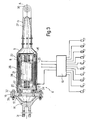
Figure 3 shows a larger-scale axial section of theFigure 1 vibration control device; -
Figure 4 shows an axial section of a further embodiment of theFigure 3 control device. - Number 1 in
Figure 1 indicates a helicopter substantially comprising arotor 2, which generates a force to sustain the helicopter as a whole; afuselage 3 for housing the crew and various equipment not shown; and aconnection assembly 4 interposed betweenrotor 2 andfuselage 3 to transmit the sustaining force tofuselage 3. - Helicopter 1 also comprises a control device 6 (shown in
Figures 1 and3 ) for controlling vibration offuselage 3, and which, in a preferred embodiment, determines the acceleration values of certain points offuselage 3, and generates a force field on the fuselage to counteract vibration. - More specifically,
control device 6 comprises a number ofaccelerometers 7 fixed to respective points offuselage 3 and for generating respective signals associated with the acceleration of the relative fastening points; and a number of actuators 8 (shown inFigure 3 ) for producing said force field. -
Control device 6 also comprises anelectronic control unit 10, which stores various characteristic parameters of helicopter 1, receives the signals generated byaccelerometers 7, and itself generates a control signal for controllingactuators 8. -
Actuators 8 are advantageously fitted directly byconnection assembly 4. - More specifically,
connection assembly 4 comprises a number of - in the example shown, four -rods 9, which houserespective actuators 8 and transmit the sustaining force from anouter casing 11 of the known pylon ofrotor 2 to a substantiallyflat top portion 12 offuselage 3. - More specifically,
casing 11 supportsrotor 2 in rotary manner, and is fixed at the bottom totop portion 12 offuselage 3 by across member 5 and byrods 9 on opposite sides ofcross member 5. - Each
rod 9 extends along a respective axis A sloping with respect totop portion 12 offuselage 3 and to the axis ofrotor 2, and hasopposite ends top portion 12, and the other tocasing 11. - More specifically, each
rod 9 comprises twomembers ends respective ends opposite ends 30, 31 - to acommon plate 16 also of axis A. As shown inFigure 3 ,ends members plate 16 and along axis A by means of a number of bolts. -
Member 13 is hollow and open atend 32, so thatplate 16 andend 30 define a closedcavity 15, insidemember 13, for housingrelative actuator 8. - Each
rod 9 has a radiallylarger region 26, which is further away axially fromend 30 than fromend 31. - More specifically,
region 26 comprisesend 33 ofmember 14;plate 16; and anaxial portion 28 ofmember 13 extending fromend 32. -
Member 13, in fact, increases in size radially fromend 30 toend 32, and, more specifically, is defined by aportion 27 extending fromend 30, and byportion 28 which is interposed axially betweenportion 27 andplate 16.Member 14 increases in size radially fromend 31 toend 33, and is shorter in axial length thanmember 13. - In the example shown (
Figures 1 and 2 ), tworods 9 haverespective members 13 connected totop portion 12, andrespective members 14 connected tocasing 11; and the other tworods 9 haverespective members 14 connected totop portion 12, andrespective members 13 connected tocasing 11. - The overall size of
connection assembly 4 is thus minimized, by tworods 9 having respective radiallylarger regions 26 close totop portion 12, and the other tworods 9 havingrespective regions 26 close tocasing 11. - With reference to
Figure 3 , eachactuator 8 is fixed torespective plate 16, and is activated byunit 10 to exert force along respective axis A onrespective rod 9. The intensity and direction of the force depend on the output signal generated byunit 10, so thatrod 9 transmits to fuselage 3 a force to reduce vibration offuselage 3. - More specifically, each
actuator 8 substantially comprises ashell 20 fixed, for example, by a number ofscrews 17, toplate 16 at asection 24 crosswise to axis A; amass 21 movable, parallel to axis A, insideshell 20 and connected elastically toshell 20; and anelectromagnetic field generator 23 controlled byunit 10 and for exerting on mass 21 a force along axis A. - More specifically,
section 24 is the onlysection connecting actuator 8 torelative rod 9, so thatactuator 8 andrelative rod 9 only exchange forces atsection 24 by means ofscrews 17. -
Mass 21 is preferably made of metal, and is connected elastically toshell 20, for example, by means of twohelical springs 22. Eachspring 22 is interposed between a respective axial end ofmass 21 andshell 20, and transmits a force, parallel to axis A, betweenmass 21 andshell 20. - In actual use, operation of
rotor 2 generates a sustaining force transmitted byrods 9 tofuselage 3, and also induces infuselage 3, viarods 9, vibration which is controlled bycontrol device 6. - More specifically,
unit 10 processes the control signal for eachgenerator 23 on the basis of the signals associated with the vibration state offuselage 3 and generated byaccelerometers 7, and on the basis of the significant helicopter parameters stored in its memory. - On the basis of the respective control signal, each
generator 23 produces a force along respective axis A to moverespective mass 21. By means ofrespective springs 22, the movement of eachmass 21 produces a force along respective axis A onrespective shell 20, and which is transmitted byrespective plate 16 torespective rod 9 atsection 24. - Depending on said force, each
rod 9 exerts a force onfuselage 3 to reduce the degree of vibration offuselage 3. - The
Figure 4 variation relates to a different embodiment of an actuator, indicated as a whole by 8', which is fitted to arespective rod 9 ofconnection assembly 4. Actuator 8' is similar toactuator 8, and is described below only as regards the differences between the two. Any corresponding or equivalent parts ofactuators 8 and 8' are indicated, where possible, using the same reference numbers. - More specifically, actuator 8' is toroidal in shape, defines a seat 25' coaxial with axis A and fitted through with
rod 9, and is fixed torod 9 at a portion ofplate 16 projecting radially outwards ofrod 9. - The advantages of helicopter 1 according to the present invention will be clear from the foregoing description.
- In particular,
control device 6 is effective in reducing vibration offuselage 3, and in reducing the energy consumption, size and weight of the equipment of helicopter 1, without imposing excessive design restrictions. -
Actuators 8, 8', in fact, are fitted toconnection assembly 4, and produce a force field which reduces vibration fromrotor 2 tofuselage 3 before the vibration spreads tofuselage 3. - More specifically, the force field is exerted in an area of
top portion 12 offuselage 3 connected torods 9. - Consequently, the alternating pattern of the force field produces no stress of
fuselage 3, which therefore requires no particular reinforcement resulting in increased weight and size. The fatigue stress in the area oftop portion 12 connected torods 9, on the other hand, calls for a smaller increase in weight, on account of this area being intrinsically heavier and larger to transmit the sustaining force fromrods 9 tofuselage 3. -
Control device 6 also consumes very little energy. In fact, by appropriately sizingsprings 22 andmass 21, the natural frequency of eachactuator 8, 8' can be tuned to the dominant frequency of the field of alternating forces generated byrotor 2 and transmitted tofuselage 3. In such conditions, very little force need be exerted by eachgenerator 23 onrespective mass 21 to achieve an effective reduction in vibration offuselage 3. - Moreover, by acting before vibration is transmitted to
fuselage 3,control device 6 provides for homogeneously controlling vibration offuselage 3, so that the location ofactuators 8, 8' does not particularly condition crew accommodation withinfuselage 3. - Finally, since each
actuator 8, 8' only exchanges forces withrespective rod 9 atrespective section 24,rods 9 andactuators 8, 8' are not subjected to particularly severe tensile/compressive stress, and therefore require no particular reinforcement resulting in increased weight and size. - Clearly, changes may be made to helicopter 1 without departing from the protective scope defined in the accompanying Claims.
Claims (5)
- A helicopter (1) comprising a rotor (2), a fuselage (3) connected to said rotor (2) by connecting means (4), and a control device (6) for controlling vibration of said fuselage (3); said control device (6) comprising generating means (7) for generating signals associated with vibration of said .fuselage (3), and actuating means (8, 8') for producing a force on said fuselage (3) associated with said signals to reduce said vibration;
said connecting means (4) comprising at least one rod (9) extending along an axis (A) and being connected, at opposite ends with respect to said axis (A), to said rotor (2) and to said fuselage (3);
said actuating means (8, 8') comprising at least one actuator (8, 8') connected to said rod (9);
characterized in that said actuator (8, 8') exchanges forces with and is connected to said rod (9) at only one section (24) crosswise to said axis (A). - A helicopter as claimed in Claim 1, characterized in that said actuator (8, 8') is housed inside a cavity (15) of said rod (9).
- A helicopter as claimed in Claim 2, characterized in that said actuator (8, 8') is located outside said rod (9).
- A helicopter as claimed in Claim 3, characterized in that said actuator (8, 8') defines a through seat (25') through which said rod (9) extends coaxially.
- A helicopter as claimed in any one of Claims 2 to 4, characterized in that said actuating means (8, 8') comprise a shell (20) connectable to said rod (9) at said section (24); a mass (21) connected elastically to said shell (20) and housed inside the shell (20); and electromagnetic force generators (23) for exerting on said mass (21) a force having a component parallel to said axis (A).
Priority Applications (6)
| Application Number | Priority Date | Filing Date | Title |
|---|---|---|---|
| DE602005008019T DE602005008019D1 (en) | 2005-05-16 | 2005-05-16 | Helicopter with improved vibration control device |
| EP05425327A EP1724191B1 (en) | 2005-05-16 | 2005-05-16 | Helicopter with an improved vibration control device |
| CA2546354A CA2546354C (en) | 2005-05-16 | 2006-05-12 | Helicopter with an improved vibration control device |
| US11/436,928 US7857255B2 (en) | 2005-05-16 | 2006-05-15 | Helicopter with an improved vibration control device |
| JP2006136570A JP5037857B2 (en) | 2005-05-16 | 2006-05-16 | Helicopter with improved vibration control device |
| JP2012057105A JP2012136219A (en) | 2005-05-16 | 2012-03-14 | Helicopter equipped with improved vibration control device |
Applications Claiming Priority (1)
| Application Number | Priority Date | Filing Date | Title |
|---|---|---|---|
| EP05425327A EP1724191B1 (en) | 2005-05-16 | 2005-05-16 | Helicopter with an improved vibration control device |
Publications (2)
| Publication Number | Publication Date |
|---|---|
| EP1724191A1 EP1724191A1 (en) | 2006-11-22 |
| EP1724191B1 true EP1724191B1 (en) | 2008-07-09 |
Family
ID=34943196
Family Applications (1)
| Application Number | Title | Priority Date | Filing Date |
|---|---|---|---|
| EP05425327A Active EP1724191B1 (en) | 2005-05-16 | 2005-05-16 | Helicopter with an improved vibration control device |
Country Status (5)
| Country | Link |
|---|---|
| US (1) | US7857255B2 (en) |
| EP (1) | EP1724191B1 (en) |
| JP (2) | JP5037857B2 (en) |
| CA (1) | CA2546354C (en) |
| DE (1) | DE602005008019D1 (en) |
Families Citing this family (23)
| Publication number | Priority date | Publication date | Assignee | Title |
|---|---|---|---|---|
| DE602005008019D1 (en) * | 2005-05-16 | 2008-08-21 | Agusta Spa | Helicopter with improved vibration control device |
| US8439299B2 (en) * | 2005-12-21 | 2013-05-14 | General Electric Company | Active cancellation and vibration isolation with feedback and feedforward control for an aircraft engine mount |
| WO2008060681A2 (en) | 2006-05-06 | 2008-05-22 | Lord Corporation | Helicopter reduced vibration isolator axial support strut |
| BRPI0622047A2 (en) | 2006-10-12 | 2014-06-10 | Bell Helicopter Textron Inc | RIGID MOUNTING PILONE WITH VIBRATION ATTENTION |
| DE102008016418A1 (en) * | 2008-03-31 | 2009-10-01 | Airbus Deutschland Gmbh | Decoupling technique of the Stairhouse to Overhead Compartment |
| JP5022457B2 (en) * | 2010-02-17 | 2012-09-12 | 三菱重工業株式会社 | Vibration reducing apparatus and vibration reducing method |
| JP4823368B2 (en) * | 2010-02-26 | 2011-11-24 | 三菱重工業株式会社 | Vibration reducing apparatus and vibration reducing method |
| FR2975668B1 (en) * | 2011-05-27 | 2013-07-05 | Eurocopter France | METHOD AND AIRCRAFT PROVIDED WITH DEVICE FOR VIBRATION REDUCTION |
| GB2492965B (en) * | 2011-07-15 | 2018-05-02 | Agustawestland Ltd | A system and method for reducing the transmission of vibration from a first vibrating body to a second body |
| CN103204244A (en) * | 2013-04-24 | 2013-07-17 | 哈尔滨飞机工业集团有限责任公司 | Vibration reduction and hoisting structure for helicopter |
| EP2857313B1 (en) * | 2013-10-03 | 2015-12-23 | AGUSTAWESTLAND S.p.A. | Hover aircraft rotor comprising a vibration damping device |
| US9284048B2 (en) | 2013-10-14 | 2016-03-15 | Sikorsky Aircraft Corporation | Global airframe health characterization |
| US9365294B2 (en) * | 2013-11-21 | 2016-06-14 | Bell Helicopter Textron Inc. | Helicopter transmission mount system |
| US9254914B2 (en) * | 2013-11-21 | 2016-02-09 | Bell Helicopter Textron Inc. | Helicopter transmission mount system |
| WO2016022672A1 (en) * | 2014-08-07 | 2016-02-11 | Sikorsky Aircraft Corporation | Anti-vibration load generating aircraft actuation system |
| FR3054277B1 (en) * | 2016-07-19 | 2018-07-13 | Airbus Helicopters | RESONATOR, AND AIRCRAFT PROVIDED WITH THIS RESONATOR |
| US11932380B2 (en) | 2017-03-15 | 2024-03-19 | Textron Innovations Inc. | Vibration isolation systems for compound helicopters |
| US20180265186A1 (en) * | 2017-03-15 | 2018-09-20 | Bell Helicopter Textron Inc. | Vibration Isolation Systems for Advancing Blade Concept Rotorcraft |
| EP3599163B1 (en) * | 2018-07-27 | 2020-11-11 | LEONARDO S.p.A. | Helicopter kit |
| EP3599162B1 (en) * | 2018-07-27 | 2020-11-11 | LEONARDO S.p.A. | Helicopter kit |
| CN109268426B (en) * | 2018-11-15 | 2019-10-18 | 中国直升机设计研究所 | A kind of adjustable hydraulic power antiresonance vibration isolator of antiresonant frequency |
| US20210347470A1 (en) * | 2020-05-11 | 2021-11-11 | Subaru Corporation | Rotary-wing aircraft |
| US20220144416A1 (en) * | 2020-11-08 | 2022-05-12 | Bell Textron Inc. | Liquid inertia vibration elimination system with compound period strut |
Family Cites Families (13)
| Publication number | Priority date | Publication date | Assignee | Title |
|---|---|---|---|---|
| FR1506385A (en) * | 1966-09-16 | 1967-12-22 | Sud Aviation | Method of attenuation and electro-hydraulic vibration attenuator for rotary wing aerodyne |
| US3635427A (en) * | 1969-05-06 | 1972-01-18 | Textron Inc | Aircraft vibration compensation system |
| US4819182A (en) * | 1985-06-21 | 1989-04-04 | Westland Plc | Method and apparatus for reducing vibration of a helicopter fuselage |
| FR2629545B1 (en) * | 1988-03-30 | 1993-02-19 | Aerospatiale | ELASTIC COUNTER SHEET WITH INTEGRATED HYDRO-MECHANICAL RESONATOR IN PARTICULAR FOR SUSPENSION OF A TRANSMISSION BOX ON A GIRAVION AND SUSPENSION DEVICE INCLUDING APPLICATION |
| GB9104190D0 (en) * | 1991-02-28 | 1991-06-12 | Westland Helicopters | Strut assemblies |
| GB9104189D0 (en) * | 1991-02-28 | 1991-06-12 | Westland Helicopters | Active vibration control systems |
| FR2680848B1 (en) * | 1991-08-29 | 1995-03-17 | Aerospatiale Ste Nat Indle | METHOD AND DEVICE FOR FILTERING THE VIBRATORY EXCITATIONS TRANSMITTED BETWEEN TWO PARTS, IN PARTICULAR BETWEEN THE ROTOR AND THE FUSELAGE OF A HELICOPTER. |
| US5231336A (en) * | 1992-01-03 | 1993-07-27 | Harman International Industries, Inc. | Actuator for active vibration control |
| JPH05193580A (en) * | 1992-01-20 | 1993-08-03 | Mitsubishi Heavy Ind Ltd | Vibration damping device for helicopter |
| GB9523651D0 (en) * | 1995-11-18 | 1996-01-17 | Gkn Westland Helicopters Ltd | Helicopter and method for reucing vibration of a helicopter fuselage |
| US5810319A (en) * | 1997-04-17 | 1998-09-22 | Applied Power Inc. | Adaptively tuned vibration absorber with dual flexures |
| JP2000035079A (en) * | 1998-07-17 | 2000-02-02 | Teijin Seiki Co Ltd | Composite ultra-magnetostriction element, ultra- magnetostriction element actuator and vibration damping device |
| DE602005008019D1 (en) * | 2005-05-16 | 2008-08-21 | Agusta Spa | Helicopter with improved vibration control device |
-
2005
- 2005-05-16 DE DE602005008019T patent/DE602005008019D1/en active Active
- 2005-05-16 EP EP05425327A patent/EP1724191B1/en active Active
-
2006
- 2006-05-12 CA CA2546354A patent/CA2546354C/en not_active Expired - Fee Related
- 2006-05-15 US US11/436,928 patent/US7857255B2/en active Active
- 2006-05-16 JP JP2006136570A patent/JP5037857B2/en active Active
-
2012
- 2012-03-14 JP JP2012057105A patent/JP2012136219A/en active Pending
Also Published As
| Publication number | Publication date |
|---|---|
| CA2546354A1 (en) | 2006-11-16 |
| CA2546354C (en) | 2014-04-01 |
| JP2012136219A (en) | 2012-07-19 |
| US7857255B2 (en) | 2010-12-28 |
| DE602005008019D1 (en) | 2008-08-21 |
| US20090321556A1 (en) | 2009-12-31 |
| EP1724191A1 (en) | 2006-11-22 |
| JP5037857B2 (en) | 2012-10-03 |
| JP2007015681A (en) | 2007-01-25 |
Similar Documents
| Publication | Publication Date | Title |
|---|---|---|
| EP1724191B1 (en) | Helicopter with an improved vibration control device | |
| EP2071924B1 (en) | Vibration-attenuating hard-mounted pylon | |
| US6279704B1 (en) | Device for reducing the vibration generated on the structure of a rotary-wing aircraft | |
| EP0382480B1 (en) | Vibration attenuating method utilizing continuously variable semiactive damper | |
| US4819182A (en) | Method and apparatus for reducing vibration of a helicopter fuselage | |
| US5732905A (en) | System for minimizing the dynamic excitation of a helicopter | |
| KR101389124B1 (en) | An aircraft provided with a device for reducing vibration, and a method therefor | |
| EP1659309B1 (en) | Vibration damping apparatus | |
| US6467723B1 (en) | Active vibration control system for helicopter with improved actustor placement | |
| EP2576340A2 (en) | A device for an adjustable flap of a wing | |
| EP2279359A1 (en) | Method and device for actively damping vertical oscillations in a helicopter having an attached exterior payload | |
| US20150069173A1 (en) | Antivibration suspension device for a mechanical element, and an aircraft | |
| EP0501658B1 (en) | Strut assemblies | |
| EP3112721B1 (en) | Vibration isolating device for an elastic coupling of two components | |
| KR101416518B1 (en) | Antivibration suspension means for a tie bar of an aircraft power transmission gearbox, an antivibration suspension device, and an aircraft | |
| EP3573890B1 (en) | Thrust link with tuned absorber | |
| US5813626A (en) | Suspension device for a transmission box of a rotary-wing aircraft | |
| GB2160840A (en) | Method and apparatus for reducing vibration of a helicopter fuselage | |
| EP3191734B1 (en) | A vibration absorbing device for reducing vibrations and sounds in a structure | |
| EP2718187B1 (en) | Device for reducing structural vibrations of aerofoils | |
| Boller | Shape Memory Alloys–Their challenge to contribute to smart structures | |
| Dayou et al. | Optimum tuning of a vibration neutralizer for global vibration control | |
| JPH0781693A (en) | Active vibration control device for helicopter | |
| JPH07267192A (en) | Helicopter | |
| Brennan | A comparison between active and semi-active control of a simple vibrating system |
Legal Events
| Date | Code | Title | Description |
|---|---|---|---|
| PUAI | Public reference made under article 153(3) epc to a published international application that has entered the european phase |
Free format text: ORIGINAL CODE: 0009012 |
|
| 17P | Request for examination filed |
Effective date: 20060512 |
|
| AK | Designated contracting states |
Kind code of ref document: A1 Designated state(s): AT BE BG CH CY CZ DE DK EE ES FI FR GB GR HU IE IS IT LI LT LU MC NL PL PT RO SE SI SK TR |
|
| AX | Request for extension of the european patent |
Extension state: AL BA HR LV MK YU |
|
| AKX | Designation fees paid |
Designated state(s): DE FR GB IT |
|
| GRAP | Despatch of communication of intention to grant a patent |
Free format text: ORIGINAL CODE: EPIDOSNIGR1 |
|
| GRAS | Grant fee paid |
Free format text: ORIGINAL CODE: EPIDOSNIGR3 |
|
| RAP1 | Party data changed (applicant data changed or rights of an application transferred) |
Owner name: AGUSTA S.P.A. |
|
| GRAA | (expected) grant |
Free format text: ORIGINAL CODE: 0009210 |
|
| AK | Designated contracting states |
Kind code of ref document: B1 Designated state(s): DE FR GB IT |
|
| REG | Reference to a national code |
Ref country code: GB Ref legal event code: FG4D |
|
| REF | Corresponds to: |
Ref document number: 602005008019 Country of ref document: DE Date of ref document: 20080821 Kind code of ref document: P |
|
| PLBE | No opposition filed within time limit |
Free format text: ORIGINAL CODE: 0009261 |
|
| STAA | Information on the status of an ep patent application or granted ep patent |
Free format text: STATUS: NO OPPOSITION FILED WITHIN TIME LIMIT |
|
| 26N | No opposition filed |
Effective date: 20090414 |
|
| REG | Reference to a national code |
Ref country code: FR Ref legal event code: PLFP Year of fee payment: 12 |
|
| REG | Reference to a national code |
Ref country code: FR Ref legal event code: PLFP Year of fee payment: 13 |
|
| REG | Reference to a national code |
Ref country code: FR Ref legal event code: PLFP Year of fee payment: 14 |
|
| REG | Reference to a national code |
Ref country code: DE Ref legal event code: R082 Ref document number: 602005008019 Country of ref document: DE Representative=s name: TER MEER STEINMEISTER & PARTNER PATENTANWAELTE, DE Ref country code: DE Ref legal event code: R081 Ref document number: 602005008019 Country of ref document: DE Owner name: LEONARDO S.P.A., IT Free format text: FORMER OWNER: AGUSTA S.P.A., SAMARATE, IT |
|
| PGFP | Annual fee paid to national office [announced via postgrant information from national office to epo] |
Ref country code: IT Payment date: 20230505 Year of fee payment: 19 Ref country code: FR Payment date: 20230523 Year of fee payment: 19 Ref country code: DE Payment date: 20230530 Year of fee payment: 19 |
|
| PGFP | Annual fee paid to national office [announced via postgrant information from national office to epo] |
Ref country code: GB Payment date: 20230523 Year of fee payment: 19 |
|
| P01 | Opt-out of the competence of the unified patent court (upc) registered |
Effective date: 20231005 |