EP1724005A1 - Liquid agitating device - Google Patents
Liquid agitating device Download PDFInfo
- Publication number
- EP1724005A1 EP1724005A1 EP05720386A EP05720386A EP1724005A1 EP 1724005 A1 EP1724005 A1 EP 1724005A1 EP 05720386 A EP05720386 A EP 05720386A EP 05720386 A EP05720386 A EP 05720386A EP 1724005 A1 EP1724005 A1 EP 1724005A1
- Authority
- EP
- European Patent Office
- Prior art keywords
- liquid
- sound wave
- agitating device
- transmitting portion
- liquid agitating
- Prior art date
- Legal status (The legal status is an assumption and is not a legal conclusion. Google has not performed a legal analysis and makes no representation as to the accuracy of the status listed.)
- Granted
Links
Images


Classifications
-
- B—PERFORMING OPERATIONS; TRANSPORTING
- B01—PHYSICAL OR CHEMICAL PROCESSES OR APPARATUS IN GENERAL
- B01F—MIXING, e.g. DISSOLVING, EMULSIFYING OR DISPERSING
- B01F31/00—Mixers with shaking, oscillating, or vibrating mechanisms
- B01F31/20—Mixing the contents of independent containers, e.g. test tubes
- B01F31/28—Mixing the contents of independent containers, e.g. test tubes the vibrations being caused by piezoelectric elements
-
- B—PERFORMING OPERATIONS; TRANSPORTING
- B01—PHYSICAL OR CHEMICAL PROCESSES OR APPARATUS IN GENERAL
- B01F—MIXING, e.g. DISSOLVING, EMULSIFYING OR DISPERSING
- B01F31/00—Mixers with shaking, oscillating, or vibrating mechanisms
- B01F31/80—Mixing by means of high-frequency vibrations above one kHz, e.g. ultrasonic vibrations
- B01F31/85—Mixing by means of high-frequency vibrations above one kHz, e.g. ultrasonic vibrations with a vibrating element inside the receptacle
-
- B—PERFORMING OPERATIONS; TRANSPORTING
- B01—PHYSICAL OR CHEMICAL PROCESSES OR APPARATUS IN GENERAL
- B01F—MIXING, e.g. DISSOLVING, EMULSIFYING OR DISPERSING
- B01F31/00—Mixers with shaking, oscillating, or vibrating mechanisms
- B01F31/80—Mixing by means of high-frequency vibrations above one kHz, e.g. ultrasonic vibrations
- B01F31/86—Mixing by means of high-frequency vibrations above one kHz, e.g. ultrasonic vibrations with vibration of the receptacle or part of it
-
- G—PHYSICS
- G01—MEASURING; TESTING
- G01N—INVESTIGATING OR ANALYSING MATERIALS BY DETERMINING THEIR CHEMICAL OR PHYSICAL PROPERTIES
- G01N1/00—Sampling; Preparing specimens for investigation
- G01N1/28—Preparing specimens for investigation including physical details of (bio-)chemical methods covered elsewhere, e.g. G01N33/50, C12Q
- G01N1/38—Diluting, dispersing or mixing samples
Landscapes
- Chemical & Material Sciences (AREA)
- Chemical Kinetics & Catalysis (AREA)
- Automatic Analysis And Handling Materials Therefor (AREA)
- Mixers With Rotating Receptacles And Mixers With Vibration Mechanisms (AREA)
Abstract
Description
- The present invention relates to a liquid agitating device.
- A conventional agitating apparatus that agitates an agitated liquid with an agitator enhances an agitating effect and reduces agitating time by positioning a tip end of the agitator substantially at a middle level of the agitated liquid (see Patent Document 1, for example). Further, a chemical analyzer that is provided with an ultrasound generator for agitating an agitated liquid with ultrasound has a piezoelectric transducer, being a ultrasonic generator, with separate electrodes, and drives control the separate electrodes so as to generate a sound wave with an appropriate intensity at an appropriate position for generation of swirling flow (see
Patent Document 2, for example). - Patent Document 1:
Japanese Patent Application Laid-Open No. H6-258328
Patent Document 2:Japanese Patent Application Laid-Open No. 2001-215232 - However, when the agitated liquid is minute in amount, the agitating apparatus of Patent Document 1 cannot easily place the tip end of the agitator at a position substantially at the middle of the agitated liquid. The agitating apparatus is sometimes unable to agitate the liquid of minute amount. On the other hand, the agitating apparatus of
Patent Document 2 tends to have a complicated structure since the agitating apparatus determines which electrode is to be driven among the separate electrodes depending on the amount of liquid and therefore needs, for example, a liquid level gauge and a controller to selectively drive any one of the separate electrodes. - In view of the foregoing, an object of the present invention is to provide a liquid agitating device which allows for a liquid agitation with a simple structure.
- In order to solve the problems as described above and to achieve an object, a liquid agitating device according to one aspect of the present invention generates a flow within a liquid to agitate the liquid, and includes a sound wave generator that generates a sound wave, and a transmitting portion that transmits the sound wave generated by the sound wave generator, at least a portion of the transmitting portion being in contact with the liquid, and the transmitting portion emitting the sound wave towards the liquid at the portion in contact with the liquid, and the sound wave emitted toward the liquid generates a local flow within the liquid and agitates the liquid.
- In the liquid agitating device of the above described aspect, the sound wave generated by the sound wave generator transmits through the transmitting portion and leaks out from the portion in contact with the liquid to the liquid side. At this time, the transverse wave such as the surface acoustic wave cannot propagate through a fluid such as a liquid. Hence, the transverse wave is subjected to the mode conversion in the transmitting portion in contact with the liquid, and the mode-converted longitudinal wave transmits through and propagates into the liquid. Since this portion is a surface of the transmitting portion immediately below a liquid level in the vicinity of an air-liquid interface, the longitudinal wave makes the air-liquid interface fluctuate effectively to agitate the liquid.
- Further, in the liquid agitating device according to another aspect of the present invention, the sound wave generator is formed on a surface of the transmitting portion.
- In the liquid agitating device of the above described aspect, the sound wave generator is formed on the surface of the transmitting portion. Therefore, when the sound wave generator is a piezoelectric body having Inter Digital Transducers (IDT) on the surface, for example, the sound wave energy can be concentrated in a close proximity to the surface of the transmitting portion. Further, if the sound wave generator is an angle transducer or the like which makes the sound wave incident on the transmitting portion at a predetermined angle, for example, the sound wave repeatedly undergoes total reflection at the surface of the transmitting portion during transmission.
- Further, in the liquid agitating device according to still another aspect of the present invention, the sound wave generator is arranged at a position not in contact with the liquid.
- In the liquid agitating device of the above described aspect, the fluid in contact with the transmitting portion, on which the sound wave generator is arranged, is an atmosphere represented by air or atmospheric air at the time of agitation. Since acoustic impedances of two substances are largely different from each other, the sound wave is confined in the transmitting portion during propagation. Therefore, the loss of the sound wave in the propagation can be limited to a minimum level.
- Further, in the liquid agitating device according to still another aspect of the present invention, the sound wave generator generates a surface acoustic wave as the sound wave.
- In the liquid agitating device of the above described aspect, when the high frequency alternating electric field of approximately a few MHz to a few hundred MHz is applied to the sound wave generator, and if a resonance condition is substantially satisfied, i.e., if the frequency is substantially equal to the ratio of the speed of surface sound wave to the distance between the electrodes in the sound wave generator, the surface acoustic wave is induced. The direction of propagation of the surface acoustic wave is the direction of arrangement of the electrodes that engage with each other. The surface acoustic wave propagates along the transmitting portion towards the liquid to be agitated. When the acoustic impedance of the transmitting portion is largely different from the acoustic impedance of the fluid in contact with the transmitting portion, the surface acoustic wave is confined in a region approximately one wavelength deep from the surface of the transmitting portion during advancement in the direction of propagation. Hence, extremely high energy is confined in the vicinity of the surface of the transmitting portion, which leads to an excellent conversion efficiency of the energy radiating from the portion in contact with the liquid. Since the sound wave generator is formed on the surface of the transmitting portion, the loss of the sound wave during propagation can be minimized, and the sound wave radiated towards the desired liquid is substantially at the same intensity with the intensity of the sound wave at the generation. In the liquid agitating device of the above described aspect, the sound wave energy is concentrated in the close proximity to the surface of the transmitting portion. In addition, the difference in the acoustic impedance of the transmitting portion and the liquid is utilized, so that the longitudinal wave is radiated toward the liquid at a specific angle when the transmitting portion comes into contact with the liquid.
- Further, in the liquid agitating device according to still another aspect of the present invention, the transmitting portion is in contact with an ambient gas in a portion other than a portion located in the liquid.
- Further, in the liquid agitating device according to still another aspect of the present invention, the ambient gas is air.
- In the liquid agitating device of the above described aspect, when the fluid in contact with the transmitting portion is an ambient gas (air), since the acoustic impedance of the air is largely different from the acoustic impedance of the transmitting portion, the sound wave propagates while being confined within the transmitting portion.
- Further, in the liquid agitating device according to still another aspect of the present invention, in the transmitting portion, the portion emitting the sound wave towards the liquid is present on a liquid side with respect to an air-liquid interface of the ambient gas and the liquid, and an acoustic impedance is discontinuous at the air-liquid interface.
- In the liquid agitating device of the above described aspect, at the air-liquid interface where the acoustic impedance is discontinuous, the sound wave is radiated toward the liquid in a concentrated manner. Thus, it is possible to facilitate the interface fluctuation.
- Further, in the liquid agitating device according to still another aspect of the present invention, the transmitting portion has an acoustic impedance which is higher than an acoustic impedance of the liquid, and lower than an acoustic impedance of the sound wave generator.
- In the liquid agitating device of the above described aspect, the sound wave transmits from the transmitting portion which has a high acoustic impedance to the liquid which has a low acoustic impedance while the loss of the sound wave is suppressed.
- Further, in the liquid agitating device according to still another aspect of the present invention, in the transmitting portion, the acoustic impedance decreases from a portion of the sound wave generator towards the portion emitting the sound wave towards the liquid.
- In the liquid agitating device of the above described aspect, the sound wave transmits from a side of the sound wave generator which has a high acoustic impedance to a side in contact with the liquid which has a low acoustic impedance while the loss of the sound wave is suppressed.
- Further, in the liquid agitating device according to still another aspect of the present invention, in the transmitting portion, an acoustic impedance of the portion emitting the sound wave toward the liquid is closer to an acoustic impedance of the portion in contact with the ambient gas than to an acoustic impedance of the ambient gas.
- In the liquid agitating device of the above described aspect, when the fluid in contact with the transmitting portion is air or atmospheric air, for example, the acoustic impedance of the transmitting portion and the acoustic impedance of the air or atmospheric air are largely different from each other. Hence, the sound wave propagates while being confined in the surface of the solid substrate. On the other hand, when the fluid in contact with the transmitting portion is a liquid to be agitated, the acoustic impedance of the transmitting portion is relatively close to the acoustic impedance of the liquid. Hence, the sound wave is leaked out to the side of the liquid.
- Further, in the liquid agitating device according to still another aspect of the present invention, in the transmitting portion, transmittivity of the sound wave in a direction of propagation of the sound wave in the portion emitting the sound wave toward the liquid in a portion in the liquid is higher than transmittivity of the sound wave in a portion which is in the ambient gas and from which the sound wave is leaked out to the ambient gas.
- In the liquid agitating device of the above described aspect, the sound wave propagates to the portion in contact with the liquid while extremely high energy is confined in the transmitting portion. In other words, the energy loss from the propagation is suppressed and the high energy level is maintained until the sound wave comes to the portion in contact with the liquid. Therefore, the conversion efficiency of the energy to be radiated from the portion in contact with the liquid to the liquid is excellent.
- Further, in the liquid agitating device according to still another aspect of the present invention, in the transmitting portion, a position of the portion emitting the sound wave towards the liquid changes according to a position of the air-liquid interface.
- In the liquid agitating device of the above described aspect, the liquid is effectively agitated in the vicinity of the air-liquid interface even though a complicated position controller is not provided.
- Further, in the liquid agitating device according to still another aspect of the present invention, a direction of sound wave emission toward the liquid has a direction component which is opposite to a direction component of a gravitational force.
- The liquid agitating device of the above described aspect can generate a flow moving from below to the above, whereby an ingredient which tends to be deposited at the bottom can be efficiently agitated.
- Further, in the liquid agitating device according to still another aspect of the present invention, in the transmitting portion, the position where the sound wave is emitted toward the liquid is the air-liquid interface.
- In the liquid agitating device of the above described aspect, the longitudinal wave is emitted into the liquid in the vicinity of the air-liquid interface, whereby the interface fluctuation can be facilitated.
- Further, in the liquid agitating device according to still another aspect of the present invention, the transmitting portion is formed of a piezoelectric body.
- In the liquid agitating device of the above described aspect, the loss of the sound wave, which is generated by the sound wave generator, during the propagation can be suppressed effectively.
- Further, in the liquid agitating device according to still another aspect of the present invention, in the transmitting portion, the portion emitting the sound wave toward the liquid is located at a different position from a position of the sound wave generator.
- In the liquid agitating device of the above described aspect, in the transmitting portion, a portion which emits the sound wave is located at a different position from a position of the sound wave generator. Hence, the portion in which the sound wave generator resides does not touch the liquid to be agitated, whereby the contamination by the liquid is completely eliminated.
- Further, the liquid agitating device according to still another aspect of the present invention, further includes a controlling device that controls frequency, amplitude, driving time, or a driving timing of the sound wave generator.
- In the liquid agitating device of the above described aspect, the controlling device controls, for example, waveform, amplitude, time of application, timing of application, and the like of the high-frequency alternating electric field of approximately a few MHz to a few hundred MHz applied to the sound wave generator. The controlling device achieves an efficient agitation by giving an optimal driving vibration by setting these parameters in accordance with the type, amount, and the like of the liquid to be agitated.
- Further, in the liquid agitating device according to still another aspect of the present invention, the transmitting portion further includes a sound wave detector that detects the sound wave generated by the sound wave generator, and the sound wave detector includes a processor that performs signal processing on the sound wave detected.
- In the liquid agitating device of the above described aspect, the sound wave detector detects whether the transmitting portion is brought into contact with the liquid or not. Therefore, the liquid agitating device can be utilized as a detector to detect whether the liquid is contained in the container or not.
- Further, the liquid agitating device according to still another aspect of the present invention includes a processor that performs a signal processing on the sound wave, and the sound wave generator receives a reflected wave of the sound wave, the sound wave being transmitted through the transmitting portion and reflected at an end face, the sound wave generator further outputs the received sound wave to the processor.
- In the liquid agitating device of the above described aspect, a separate sound wave detector does not need to be provided in the transmitting portion, and still the liquid agitating device can be utilized as a detector to detect whether the transmitting portion is immersed in the liquid or not. The sound wave generator may be an angle transducer.
- Further, in the liquid agitating device according to still another aspect of the present invention, in the transmitting portion, a width of the portion in contact with the liquid and emitting the sound wave toward the liquid is narrower than a width of a portion where the sound wave generator is provided.
- In the liquid agitating device of the above described aspect, the sound wave generated by the sound wave generator is reflected and amplified within the transmitting portion, whereby the sound wave with amplified intensity is present in the portion emitting the sound wave toward the liquid. Further, since the liquid agitating device is tapered toward the portion emitting the sound wave, the liquid agitating device can be more easily inserted into the liquid to be agitated.
- Further, in the liquid agitating device according to still another aspect of the present invention, in the transmitting, portion, a width constantly decreases or monotonously decreases from the portion where the sound wave generator is provided towards the portion emitting the sound wave to the liquid.
- Further, in the liquid agitating device according to still another aspect of the present invention, in the transmitting portion, the width linearly decreases or exponentially decreases from the portion where the sound wave generator is provided towards the portion emitting the sound wave toward the liquid.
- In the liquid agitating device of the above described aspect, the sound wave is repeatedly reflected within the transmitting portion during propagation thereof, whereby the resonance effect is enhanced. In brief, the amplitude of the mode-converted longitudinal wave which is emitted toward the liquid is amplified, and the agitating effect of the liquid is enhanced.
- Further, in the liquid agitating device according to still another aspect of the present invention, the sound wave generator is formed in a circular arc shape so that the generated sound wave is focused on a predetermined position in the transmitting portion.
- In the liquid agitating device of the above described aspect, the sound wave energy can be concentrated on a predetermined position. Therefore, the longitudinal wave with extremely high energy can be emitted toward the liquid, whereby the agitating effect of the liquid can be enhanced.
- Further, in the liquid agitating device according to still another aspect of the present invention, the transmitting portion further includes a waveguide that guides the focused sound wave, and the sound wave generator focuses the generated sound wave at an inlet of the waveguide.
- In the liquid agitating device of the above described aspect, the energy of the surface acoustic wave is concentrated and amplified on the waveguide. Therefore, a strong longitudinal wave can be emitted toward the liquid not only from the tip end of the liquid agitating device but also from any positions on the waveguide.
- Further, in the liquid agitating device according to still another aspect of the present invention, the transmitting portion further includes a reflector that amplifies the sound wave generated by the sound wave generator.
- In the liquid agitating device of the above described aspect, the state of the resonance of the surface acoustic wave is enhanced to amplify the energy. Therefore, the longitudinal wave with extremely large amplitude is emitted toward the liquid, whereby the agitating effect of the liquid is enhanced.
- Further, in the liquid agitating device according to still another aspect of the present invention, in the transmitting portion, at least a part of the transmitting portion is a part of the container containing the liquid.
- In the liquid agitating device of the above described aspect, the liquid agitating device can be arranged outside the container containing the liquid.
- Further, in the liquid agitating device according to still another aspect of the present invention, in the transmitting portion, the portion emitting the sound wave toward the liquid is a part of the container.
- In the liquid agitating device of the above described aspect, there is no need of direct contact with the liquid. Therefore, the contamination of the liquid agitating device can be prevented, when, for example, the liquid agitating device is employed for a biochemical examination.
- Further, in the liquid agitating device according to still another aspect of the present invention, an acoustic impedance is discontinuous at an interface between the container and the ambient gas.
- In the liquid agitating device of the above described aspect, the sound wave is not emitted from the interface between the ambient gas and the container.
- Further, in the liquid agitating device according to still another aspect of the present invention, in the transmitting portion, the portion emitting the sound wave toward the liquid extends in a direction of gravitational force.
- In the liquid agitating device of the above described aspect, various manners of arrangement can be employed. For example, an agitator can be inserted and arranged inside the container, or the agitator can be arranged outside the container in contact with the container. Thus, a degree of freedom can be increased with respect to usage.
- Further, in the liquid agitating device according to still another aspect of the present invention, in the transmitting portion, the portion emitting the sound wave towards the liquid extends in a horizontal direction.
- In the liquid agitating device of the above described aspect, the longitudinal wave can be emitted toward the liquid in a direction from the bottom surface of the container toward the air-liquid interface. Therefore, the deposition of a solution or sample with a high specific gravity can be prevented, and at the same time, the interface fluctuation can be facilitated.
- Further, in order to solve the problems as described above and to achieve an object, a liquid agitating device according to still another aspect of the present invention generates a flow in a liquid contained in a container having a predetermined capacity, to agitate the liquid. The liquid agitating device includes a sound wave generator that generates a sound wave; and a transmitting portion that receives and transmits the sound wave generated by the sound wave generator, and that is in contact with two substances having different levels of acoustic impedance. The transmitting portion has a portion that emits the sound wave toward the liquid from a portion which is on a surface of the transmitting portion and which intersects with an interface between the substances in contact with the transmitting portion.
- Further, in the liquid agitating device according to still another aspect of the present invention, a volume of the liquid changes within a predetermined range.
- The liquid agitating device according to the present invention is advantageous in that the liquid agitating device can agitate the liquid with a simple structure.
- FIG. 1 is a schematic perspective view of a structure of an agitator including an IDT arranged on a piezoelectric substrate in a liquid agitating device according to a first embodiment;
- FIG. 2 is a diagram of the agitator placed inside a container containing a liquid for use;
- FIG. 3 is an enlarged view of a portion A of FIG. 2;
- FIG. 4 is an explanatory diagram illustrating an effect of an increased amount of a target liquid inside the container which causes a change in liquid level;
- FIG. 5 is a diagram showing a relation between an incident angle of a surface acoustic wave which is incident on an interface between the agitator and fluid, and an angle of transmission of a longitudinal wave which transmits through and is leaked into the fluid;
- FIG. 6 is a diagram of a modification of the agitator according to the first embodiment;
- FIG. 7 is a diagram of another modification of the agitator according to the first embodiment;
- FIG. 8 is a schematic diagram of a basic structure of a liquid agitating device according to a second embodiment of the present invention;
- FIG. 9 is an enlarged view showing how leaky surface acoustic wave and bulk wave propagate in the liquid agitating device of FIG. 8;
- FIG. 10 is a diagram showing how waves propagate in a transmitting portion;
- FIG. 11 is an explanatory diagram of an effect of an increased amount of the target liquid inside the container which causes a change in liquid level;
- FIG. 12 is a diagram of a first modification of the liquid agitating device according to the second embodiment;
- FIG. 13 is a diagram of a second modification of the liquid agitating device according to the second embodiment;
- FIG. 14 is a diagram of a third modification of the liquid agitating device according to the second embodiment;
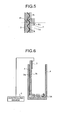
- FIG. 15 is a diagram of a fourth modification of the liquid agitating device according to the second embodiment;
- FIG. 16 is a diagram of a fifth modification of the liquid agitating device according to the second embodiment;
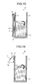
- FIG. 17 is an enlarged view showing how the ultrasound is leaked out into the liquid from a functioning portion on a wall surface of the container in the liquid agitating device according to the fifth modification;
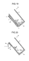
- FIG. 18A is a schematic diagram showing a basic structure of a liquid agitating device according to a third embodiment;
- FIG. 18B shows an example of interface fluctuation caused by the liquid agitating device of FIG. 18A;
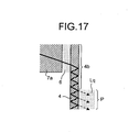
- FIG. 19 is a schematic diagram of a first modification of the liquid agitating device according to the third embodiment;
- FIG. 20 is a schematic diagram of a second modification of the liquid agitating device according to the third embodiment;
- FIG. 21 is a schematic diagram of a liquid agitating device according to a fourth embodiment;
- FIG. 22 is a schematic diagram of a modification of the liquid agitating device shown in FIG. 21;
- FIG. 23 is a schematic diagram of another modification;
- FIG. 24 is a front elevational view of a liquid agitating device according to a fifth embodiment;
- FIG. 25 is a front elevational view of a modification of an agitator shown in FIG. 24;
- FIG. 26 is a front elevational view of another example of the liquid agitating device according to the fifth embodiment;
- FIG. 27 is a front elevational view of still another example of the liquid agitating device according to the fifth embodiment; and
- FIG. 28 is a front elevational view of a liquid agitating device according to a sixth embodiment.
-
- 2
- Agitator
- 2a
- Substrate
- 2b
- Transmitting portion
- 3
- Piezoelectric transducer
- 3a, 3b
- Comb-shaped electrode
- 3c
- Extraction electrode
- 4
- Container
- 5
- Controlling device
- 6
- Acoustic matching layer
- 7
- Agitator
- 7a
- Wedge
- 7b
- Angle transducer
- 8
- Sound wave detector
- 9
- Processor
- 10, 15
- Liquid agitating device
- 20, 25
- Liquid agitating device
- 30, 35
- Liquid agitating device
- 35a
- Substrate
- 36
- Piezoelectric transducer
- 40, 45
- Liquid agitating device
- 41, 46
- Piezoelectric transducer
- 50, 55
- Liquid agitating device
- 51, 56
- Piezoelectric transducer
- 52
- Waveguide
- 57
- grating
- P
- Functioning portion
- FIRST EMBODIMENT
A liquid agitating device according to a first embodiment of the present invention will be described in detail below with reference to the accompanying drawings. FIG. 1 is a perspective view showing a schematic structure of an agitator which includes an IDT arranged on a piezoelectric substrate in the liquid agitating device. FIG. 2 shows how the agitator is arranged during use inside a container which has a predetermined capacity and contains liquid. FIG. 3 is an enlarged view of a portion A of FIG. 2. FIG. 4 illustrates an effect of an increased amount of target liquid in the container which causes a change in liquid level. - An
agitator 2 has, as shown in FIG. 1, apiezoelectric transducer 3 consisting of bamboo-blind-like or comb-shaped electrodes (i.e., IDT: Inter Digital Transducer) 3a and 3b in a transmittingportion 2b on a surface of asubstrate 2a. Thepiezoelectric transducer 3 serves as a surface acoustic wave generator. The comb-shapedelectrodes agitator 2 is inserted into acontainer 4 containing liquid Lq from anopening 4a of thecontainer 4 so as to come into contact with the liquid Lq, while thepiezoelectric transducer 3 is positioned above the liquid Lq in a direction of gravitational force or at such a position that thepiezoelectric transducer 3 does not come into contact with the liquid Lq. Theagitator 2 is sufficiently long so that at least the tip end thereof reaches a bottom surface of thecontainer 4. Thepiezoelectric transducer 3 is manufactured by semiconductor manufacturing technique, and for example, the comb-shapedelectrodes - In the present invention, the transmitting
portion 2b is a portion that transmits the sound wave (surface acoustic wave) on the surface of the substrate. As shown in FIG. 3, at least a part of the transmittingportion 2b comes into contact with the liquid Lq and transmits the sound wave (surface acoustic wave) generated by thepiezoelectric transducer 3 to the liquid Lq from a portion within the portion in contact with the liquid Lq. In theagitator 2, the transmittingportion 2b is a portion that transmits the sound wave (surface acoustic wave) and is formed on the surface of asubstrate 2a. As shown in FIG. 3, the transmittingportion 2b includes a functioning portion P which comes into contact with the liquid Lq and which sends the sound wave (surface acoustic wave) generated by thepiezoelectric transducer 3 to the liquid Lq at a portion in contact with the liquid Lq. When the term "substrate" is used in the description of the transmitting portion in the present invention, the term means a solid substrate of a material, such as silicon and glass, employed in the semiconductor manufacturing technique, or a layer, such as a metal layer and an insulating layer, on the solid substrate. The term "substrate", when employed in the description of the transmitting portion, also implies a piezoelectric solid substrate of lithium niobate crystal, zinc oxide, or lead zirconate titanate (PZT), for example. Further, the term "substrate" also implies an element formed with a quartz layer or a metal layer, for example, deposited on a portion of the piezoelectric substrate, or a wall surface of thecontainer 4. - An action of the
agitator 2 will be described with reference to FIGS. 2 and 3. As shown in FIG. 2, theagitator 2 is inserted into thecontainer 4 from theopening 4a of thecontainer 4 and brought into contact with the liquid Lq contained in the container. Here, theagitator 2 is sufficiently long so that at least the tip end of theagitator 2 comes into contact with the liquid Lq. While theagitator 2 is held in the state of FIG. 2, electricity is supplied, for example, a high-frequency alternating electric field of approximately a few MHz to a few hundred MHz is applied to thepiezoelectric transducer 3. When resonance condition is substantially met, i.e., when the frequency is substantially equal to a ratio of the speed of surface sound wave to the interval (λ/4) between theelectrodes piezoelectric transducer 3, surface acoustic wave is induced in a piezoelectric region of thesubstrate 2a. - A direction of propagation of the induced surface acoustic wave is equal to the direction of arrangement of the comb-shaped
electrodes substrate 2a at the side of thepiezoelectric transducer 3. When the surface acoustic wave comes close to an air-liquid interface where thesubstrate 2a contacts with the liquid Lq, the surface acoustic wave is released to the liquid Lq, which is to be agitated, in a direction as shown by a dotted line and propagates through the liquid Lq. In general, when the acoustic impedance of the solid substrate is largely different from the acoustic impedance of the fluid in contact with the solid substrate, the surface acoustic wave is confined in a region approximately one wavelength deep from the surface of the solid substrate and advances in the propagation direction, whereas when the acoustic impedance of the solid substrate is close to the acoustic impedance of the fluid in contact therewith, the surface acoustic wave leaks out from the solid substrate to the side of the fluid. In other words, when an interface of two substances with different levels of acoustic impedance, for example, an air-liquid interface is brought into contact with the solid substrate, i.e., the transmitting portion, the energy of the surface acoustic wave propagates to a substance with higher acoustic matching with the solid substrate. - With respect to the
agitator 2, at an upper portion of thesubstrate 2a, the fluid in contact with thesubstrate 2a is an atmosphere (air) represented by air or atmospheric air, which is present at the agitation, and hence the acoustic impedance of the solid substrate is largely different from the acoustic impedance of the fluid. Therefore, the surface acoustic wave propagates within the surface of thesubstrate 2a, i.e., within the transmittingportion 2b in a portion which is in contact with the air and located above the level of the liquid Lq. On the other hand, when the fluid in contact with thesubstrate 2a is the liquid Lq, i.e., the substance to be agitated, the acoustic impedance of the solid substrate is relatively close to the acoustic impedance of the fluid. Hence, in theagitator 2, at a portion where thesubstrate 2a is in contact with the liquid Lq, i.e., where theagitator 2 is in the liquid Lq, the surface acoustic wave undergoes a mode conversion to become a longitudinal wave and is leaked out to the side of the liquid Lq. As shown in FIG. 2, thus, theagitator 2 generates a local flow shown by an anticlockwise arrow by the longitudinal wave which is generated by the mode conversion and leaked out to the liquid Lq side as indicated by a dotted line, thereby agitating the liquid Lq. - Inside the transmitting
portion 2b, the acoustic impedance gradually decreases from the portion with thepiezoelectric transducer 3 towards the portion emitting the sound wave to the liquid. A relation IT ≥ IB ≥ IL >> IA is satisfied, where the acoustic impedance of the transmittingportion 2b is IB, the acoustic impedance of the liquid Lq is IL, the acoustic impedance of the air is IA, and the acoustic impedance of thepiezoelectric transducer 3 is IT. Further, in the transmittingportion 2b, a difference between the acoustic impedance of the air and the acoustic impedance of the portion of the transmittingportion 2b in the air is larger than a difference in the acoustic impedance of the liquid Lq and the portion of the transmittingportion 2b in the liquid Lq. Still further, transmissivity of the sound wave in the propagation direction in the portion that emits the sound wave towards the liquid Lq is higher than the transmissivity of the sound wave in the portion in the air where the sound wave is leaked out into the air in the transmittingportion 2b. - A transverse wave such as surface acoustic wave cannot propagate in the fluid such as liquid. Therefore, at the interface between the
agitator 2 and the liquid, the mode conversion occurs to convert the transverse wave into the longitudinal wave according to the Snell's law cited below:
where θi is an incident angle of the surface acoustic wave which is incident on the interface between theagitator 2 and the fluid, θ1t is an angle of transmission of the longitudinal wave which transmits through the fluid or is leaked out into the fluid, Vs is acoustic velocity of the surface acoustic wave in theagitator 2, and V1 is acoustic velocity of the longitudinal wave in the fluid. - Here, the mode-converted longitudinal wave is transmitted into and propagates through the liquid Lq from the
agitator 2. A portion where the surface acoustic wave leaks out from theagitator 2 to the liquid Lq side is located immediately below the liquid level near the air-liquid interface and is a surface (functioning portion P) of thesubstrate 2a. Hence, the mode-converted longitudinal wave can efficiently cause the fluctuation in the air-liquid interface. For example, if the mode-converted longitudinal wave is approximately a few MHz to a few hundred MHz, theagitator 2 can generate a flow in the liquid Lq or the fluctuation in the air-liquid interface. On the other hand, when the mode-converted longitudinal wave is a repeating sound wave of pulses of approximately a few milliseconds to a few ten milliseconds, theagitator 2 can utilize an effect of acoustic radiation pressure to generate the fluctuation in the air-liquid interface, whereby theagitator 2 can agitate the liquid Lq by a vortex flow generated collaterally. Further, if the mode-converted longitudinal wave is a successive sound wave of at least a few ten milliseconds or more, theagitator 2 can generate a sound flow in the liquid Lq to agitate the liquid Lq. - According to the formula (1), the mode-converted longitudinal wave generated from the surface acoustic wave transmits through and leaks into the liquid while forming an angle θ1t with respect to the
agitator 2 as shown in FIG. 5. When the surface acoustic wave is a Rayleigh wave, θi = 90°. Since an angle of transmission and leakage is determined by the ratio of acoustic velocities (Vl/Vs), the longitudinal wave can be made to be emitted in a desired advance direction through a suitable selection of the acoustic velocity of the surface acoustic wave in theagitator 2. - In the
agitator 2, the portion where the surface acoustic wave leaks out from thesubstrate 2a to the liquid Lq side is determined solely by the acoustic impedance of the fluid which has an interface in contact with thesubstrate 2a. Therefore in theagitator 2, as shown in FIG. 4, the functioning portion P where the surface acoustic wave leaks out from thesubstrate 2a to the liquid Lq side changes depending on the position of the air-liquid interface, in other words, depending on the amount of the liquid Lq. Therefore, even when the amount of liquid to be agitated significantly varies, for example, even when the air-liquid interface rises from the level shown in FIG. 2 to the level shown in FIG. 4 by a height H1, theagitator 2 can generate a local flow near the air-liquid interface and agitate the liquid Lq. As can be seen from the foregoing, the portion emitting the sound wave from the transmittingportion 2b to the liquid extends in the direction of gravitational force in theagitator 2. Therefore, theagitator 2 can function properly as far as at least a part of the transmittingportion 2b is in contact with the liquid Lq, without the need of adjustment of vertical positioning in accordance with the increase/decrease in the amount of liquid, and a position detector or a controller for positioning or the like is not necessary. Thus, the agitation of liquid can be achieved in a simple structure. - In addition, the
agitator 2 of the first embodiment is advantageous in that (1) the strength of a force that works on the liquid to be agitated is adjustable based on the amplitude of the surface acoustic wave, (2) time of action, e.g., various lengths of pulse can be easily set electronically, (3) theagitator 2 can be controlled by software, (4) theagitator 2 can be easily cleansed since there is no unevenness in a portion to be immersed into the liquid, and (5) theagitator 2 can be easily held, for example, since the generation and the propagation of the surface acoustic wave occurs only in a region where the comb-shapedelectrodes piezoelectric transducer 3 intersect with each other. - Here, the
agitator 2 can be modified and changed in various manners. For example, thepiezoelectric transducer 3 may be provided not only on one side surface of thesubstrate 2 but also on another side surface of thesubstrate 2. Further, plural agitators may simultaneously be used at the agitation. - Further, the
piezoelectric transducer 3 of theagitator 2 may be controlled by a controllingdevice 5 as shown in FIG. 6. The controllingdevice 5 controls waveform, amplitude, time of application, timing of application, and the like of the high-frequency alternating electric field of approximately a few MHz to a few hundred MHz that is applied to thepiezoelectric transducer 3, for example. Theagitator 2 can realize efficient agitation by including thecontrolling device 5, and thereby providing an optimal driving vibration by suitably combining the parameters according to the type, the amount, or the like of the liquid to be agitated, for example. Thepiezoelectric transducer 3 may be provided with anextraction electrode 3c as shown in FIG. 7. Then, theagitator 2 can minimize the risk of damaging the transmittingportion 2b and facilitate the reception of the power supply. - SECOND EMBODIMENT
A liquid agitating device according to a second embodiment of the present invention will be described in detail below with reference to the accompanying drawings. FIG. 8 is a schematic diagram of a basic structure related with the liquid agitating device according to the second embodiment of the present invention. FIG. 9 is an enlarged view illustrating how leaky surface acoustic wave and bulk wave propagate in the liquid agitating device of FIG. 8. FIG. 10 shows how waves propagate in the transmitting portion. FIG. 11 illustrates an effect of an increased amount of target liquid in the container which causes a change in liquid level. - A liquid agitating
device 10 according to the second embodiment, as shown in FIG. 8, includes anagitator 2, acontainer 4, and anacoustic matching layer 6. Asubstrate 2a, a wall surface of thecontainer 4, and theacoustic matching layer 6 together form a transmitting portion. Theagitator 2 is arranged close to a side surface of thecontainer 4 with theacoustic matching layer 6 therebetween. Thesubstrate 2a of theagitator 2 is made of a piezoelectric crystalline substrate of lithium niobate crystal, quartz, lithium tantalate, or the like and cut in an optimal crystal orientation. Thepiezoelectric transducer 3 is arranged on an opposite side from the side of thecontainer 4 above the level of the liquid Lq, or at a level substantially the same as the level of the air-liquid interface of the liquid Lq. Theacoustic matching layer 6 matches theagitator 2 and thecontainer 4 with respect to the acoustic impedance. Theacoustic matching layer 6 may be made of an adhesive agent such as epoxy resin, or shellac. Alternatively, theacoustic matching layer 6 may be gel or liquid. - It is desirable that the liquid agitating
device 10 have such a structure that the acoustic impedance gradually decreases from theagitator 2, theacoustic matching layer 6, and thecontainer 4 in this order, in other words, that the acoustic impedance of the transmitting portion that transmits the sound wave monotonously decreases towards a portion that emits the sound wave towards the liquid. With such a structure, the liquid agitatingdevice 10 can minimize the loss of sound wave energy. - An action of the liquid agitating device according to the second embodiment will be described. In the liquid agitating
device 10, a piezoelectric crystalline substrate which is a substrate of lithium niobate crystal cut in a specific crystal orientation is employed as thesubstrate 2a of theagitator 2. If the resonance condition is substantially satisfied, i.e., if the frequency is substantially equal to the ratio of the speed of surface sound wave to the distance between the comb-shapedelectrodes piezoelectric transducer 3 when the high-frequency alternating electric field of approximately a few MHz to a few hundred MHz is applied to thepiezoelectric transducer 3, the leaky surface acoustic wave is induced in theagitator 2. As the leaky surface acoustic wave, wave propagation is known to concentrate its energy on the surface of the solid substrate similarly to the Rayleigh wave but emit the energy inside the substance as the bulk wave along with the propagation. FIG. 9 illustrates how the leaky surface acoustic wave WL and the bulk wave WB emitted along the propagation of the WL propagate in a portion B of FIG. 8. - The leaky surface acoustic wave propagates in a direction of arrangement of the comb-shaped
electrodes piezoelectric transducer 3 in the liquid agitatingdevice 10 of FIG. 8. On the other hand, the bulk wave WB is emitted towards inside thesubstrate 2a of theagitator 2 as shown in FIG. 9. An angle of advancement θg of the bulk wave WB depends on the crystal orientation of thecut substrate 2a. Hence, when the cut crystal orientation is selected so that the angle of advancement θg is an angle of total reflection, the bulk wave propagates through thesubstrate 2a, theacoustic matching layer 6, and the wall surface of thecontainer 4 as the transmittingportion 2b as shown in FIG. 10. Here, if the acoustic impedance of the transmittingportion 2b and the acoustic impedance of the fluid Lq which is in contact with the wall surface of thecontainer 4 are significantly different from each other, the bulk wave WB is confined in the transmitting portion during propagation. On the other hand, if the acoustic impedance of the transmitting portion and the acoustic impedance of the fluid Lq in contact with the wall surface of thecontainer 4 are close with each other, the bulk wave WB leaks out from the functioning portion P of the wall surface of thecontainer 4 towards the side of the fluid as shown by a dotted line in FIG. 10. The liquid agitatingdevice 10 generates a clockwise local flow as shown by an arrow due to the bulk wave WB leaking out from the wall surface of thecontainer 4 as shown by a dotted line in FIG. 8, thereby agitating the liquid Lq. - Since the transverse wave cannot propagate through the fluid like the liquid Lq, the mode conversion occurs from the transverse wave to the longitudinal wave according to the Snell's law as shown by the formula (1) at the interface between the wall surface of the
container 4 and the liquid. In other words, the mode-converted longitudinal wave transmits and propagates from the wall surface of thecontainer 4 to the liquid. Since the longitudinal wave transmits and propagates from the wall surface immediately below the liquid level of the container to the liquid, the mode-converted longitudinal wave can make the air-liquid interface efficiently fluctuate. For example, if the mode-converted longitudinal wave is approximately a few MHz to a few hundred MHz, theagitator 2 can generate a flow in the liquid Lq, or cause the fluctuation in the air-liquid interface. On the other hand, if the mode-converted longitudinal wave is a repeating sound wave of a pulse of approximately a few milliseconds to a few ten milliseconds, theagitator 2 can utilize the effect of acoustic radiation pressure to cause fluctuation in the interface, and agitate the liquid Lq with a vortex flow generated incidentally. Further, if the mode-converted longitudinal wave is a successive sound wave of at least a few ten milliseconds or more, theagitator 2 can generate a sound flow in the liquid Lq and agitate the liquid Lq. - Here, in the liquid agitating
device 10 according to the second embodiment, a portion where the longitudinal wave transmits to and propagates through the liquid from the wall surface of the container immediately below the liquid level depends only on the acoustic impedance of the fluid. Hence, in the liquid agitatingdevice 10, the functioning portion P where the longitudinal wave transmits and propagates through the liquid from the wall surface of the container immediately below the liquid level changes according to the position of the air-liquid interface, i.e., the amount of the liquid Lq as shown in FIG. 11. Therefore, even when the amount of liquid to be agitated significantly changes, for example, even when the air-liquid interface drops from the level shown in FIG. 8 to the level of FIG. 11 by a height H2, the liquid agitatingdevice 10 does not need to change the vertical position of theagitator 2. Therefore, the liquid agitatingdevice 10 does not need a position detector and a controller for position control. - Further, the liquid agitating
device 10 according to the second embodiment is advantageous in that (1) the strength of a force exerted to the liquid to be agitated is adjustable based on the amplitude of the leaky surface acoustic wave, (2) time of action, for example, various lengths of pulse can be easily and electronically set, (3) the liquid agitatingdevice 10 can be controlled through software, and (4) there is no contamination attributable to theagitator 2 since theagitator 2 does not come into contact with the liquid to be agitated. - Further, the liquid agitating
device 10 according to the second embodiment can be modified and changed in various manners. For example, thepiezoelectric transducer 3 can be arranged in a lower portion of theagitator 2 at a lower level than the bottom surface of thecontainer 4, depending on a design of the liquid agitatingdevice 10, the direction of agitation of the liquid Lq, or the like as shown in FIG. 12. Further, theagitator 2 may be arranged so that the transmitting portion extends in the horizontal direction at the bottom surface of thecontainer 4 as shown in FIG. 13, depending on the density of the liquid Lq to be agitated, the direction of agitation of the liquid Lq, and the like. In the examples as shown in FIGS. 12 and 13, the interface between the ambient gas and the container forms an interface of the two with different values of acoustic impedance. Further, the liquid agitatingdevice 10 can efficiently agitate the liquid Lq by includingplural agitators 2 on different wall surfaces of thecontainer 4, and driving the pluralpiezoelectric transducer 3 at random by the controllingdevice 5 as shown in FIG. 14. - Here, while the
piezoelectric transducer 3 is arranged at thecontainer 4 side of thesubstrate 2a, theextraction electrode 3c may be provided as well in theagitator 2 as shown in FIG. 15. When thepiezoelectric transducer 3 is arranged at thecontainer 4 side, the transmission and propagation of the longitudinal wave through the liquid becomes faster compared with a device in which thepiezoelectric transducer 3 arranged on an outer surface. Further, when theextraction electrode 3c is provided, the power can be easily supplied to thepiezoelectric transducer 3. Here, if theagitator 2 is arranged in the vertical direction with respect to thecontainer 4, a flow in the vertical direction is generated in the liquid. On the other hand, ifplural agitators 2 are arranged on the wall surface of thecontainer 4 in the horizontal direction, the longitudinal wave transmits and propagates in the horizontal direction in the liquid, and a flow of the horizontal direction is generated in the liquid. Hence, theplural agitators 2 may be arranged in various combinations depending on a desired flow to be generated. - Further, the liquid agitating
device 10 may include anagitator 7 as shown in FIG. 16 in place of theagitator 2 in which thepiezoelectric transducer 3 is provided. In theagitator 7, anangle transducer 7b is attached to awedge 7a, and ultrasound (longitudinal wave) generated by theangle transducer 7b may be totally reflected on the wall surface of thecontainer 4. Thus, only the wall surface of thecontainer 4 may serve as the transmittingportion 4b (see FIG. 17). Thus, the liquid agitatingdevice 10 can generate a clockwise local flow in the liquid Lq by the ultrasound leaked out from the functioning portion P on the wall surface of thecontainer 4 to the liquid Lq as shown by a dotted line in FIG. 17, to agitate the liquid Lq. Further, in the liquid agitatingdevice 10 according to the second embodiment and the modifications thereof, the portion emitting the sound wave to the liquid is provided on a different surface from the surface on which the sound wave generator is provided. Therefore, the sound wave generator is even less likely to be brought into contact with the liquid. - THIRD EMBODIMENT
A liquid agitating device according to a third embodiment of the present invention will be described in detail below with reference to the accompanying drawings. In the liquid agitating device according to the third embodiment, thecontainer 4 is arranged at an angle. FIG. 18A is a schematic diagram showing a basic structure of the liquid agitating device according to the present invention wherein the agitator is brought into direct contact with the liquid for agitation. FIG. 18B shows an example of fluctuation in the interface caused by the liquid agitating device. FIG. 19 is a schematic diagram illustrating a first modification of the liquid agitating device according to the third embodiment. FIG. 20 is a schematic diagram illustrating a second modification of the liquid agitating device according to the third embodiment. - In a liquid agitating
device 15, theagitator 2 is set in thecontainer 4 which is tilted by a predetermined angle. Here, the surface acoustic wave generated by thepiezoelectric transducer 3 of theagitator 2 undergoes the mode conversion at a portion where thesubstrate 2a is in contact with the liquid Lq to become a longitudinal wave. The mode-converted longitudinal wave transmits through and leaks out into the liquid while forming an angle θ1t with respect to theagitator 2 according to the Snell's law. For example, provided that the surface acoustic wave is Rayleigh wave, the solid substrate is of lithium niobate, and the liquid Lq is water, then the angle θ1t of transmission and leakage is approximately 22°. - Hence, if the
agitator 2 and thecontainer 4 are arranged at an angle of inclination which is larger than the angle θ1t of transmission and leakage, i.e., larger than approximately 22°, the longitudinal wave having a vertically upward component as shown in FIG. 18A is emitted towards the liquid in a direction toward the air-liquid interface from theagitator 2 as shown by a dotted line. Therefore, the liquid agitatingdevice 15 can facilitate the interface fluctuation compared with the device with the vertically arrangedagitator 2 andcontainer 4. If the longitudinal wave is a repeating sound wave of pulses of approximately a few milliseconds, the interface of the liquid comes closer to the air-liquid interface side of theagitator 2 due to the effect of the acoustic radiation pressure. Thus, the portion which has been in contact with the air is brought into contact with the liquid. Hence, as shown in FIG. 18B, more fluctuation of the interface can be induced. - The liquid agitating
device 15 can be modified and changed in various manners. For example, in the liquid agitatingdevice 15, theagitator 2 may be arranged close to the side surface of thecontainer 4 with theacoustic matching layer 6 therebetween in FIG. 19. Then, the transmitting portion may be formed with thesubstrate 2a, the wall surface of thecontainer 4, and theacoustic matching layer 6. Further, in the liquid agitatingdevice 15, theagitator 7 including theangle transducer 7b attached to thewedge 7a may be arranged on the wall surface of thecontainer 4 as shown in FIG. 20. - FOURTH EMBODIMENT
A liquid agitating device according to a fourth embodiment of the present invention will be described below with reference to FIGS. 21 to 23. The liquid agitating device according to the fourth embodiment allows for a detection of presence and absence of the liquid inside thecontainer 4. FIG. 21 is a schematic diagram of the liquid agitating device according to the fourth embodiment. FIG. 22 is a schematic diagram of a modification of the liquid agitating device shown in FIG. 21. FIG. 23 is a schematic diagram of another modification. - A liquid agitating
device 20 includes theagitator 2 provided with asound wave detector 8, apulser 3d which makes thepiezoelectric transducer 3 generate a pulse, and aprocessor 9 which processes a sound wave detected by thesound wave detector 8. Thesound wave detector 8 has a similar structure as the structure of thepiezoelectric transducer 3, and detects the surface acoustic wave generated by thepiezoelectric transducer 3. Theprocessor 9 processes signals output from thesound wave detector 8 and detects whether theagitator 2 comes into contact with the liquid Lq or not. Here, as described with reference to the first and the second embodiments, when the difference in the acoustic impedance of theagitator 2 and the acoustic impedance of the fluid in contact with theagitator 2 is significant, the surface acoustic wave generated by thepiezoelectric transducer 3 in the liquid agitating device propagates within a region approximately one wavelength deep from the surface of thesubstrate 2a. On the other hand, when the acoustic impedance of theagitator 2 and the acoustic impedance of the fluid in contact with theagitator 2 are close to each other, the surface acoustic wave is leaked out to the side of fluid from thesubstrate 2a. - Here in the liquid agitating
device 20, if theagitator 2 is not acoustically in contact with the liquid Lq in any portions, the surface acoustic wave generated by thepiezoelectric transducer 3 advances through thesubstrate 2a to the liquid side and is detected by thesound wave detector 8. On the other hand, in the liquid agitatingdevice 20, if the tip end of theagitator 2, or other portion located above the tip end in theagitator 2 comes into contact with the liquid Lq, the surface acoustic wave is leaked out from theagitator 2 to the fluid side, and hence thesound wave detector 8 does not detect anything. - Hence, with the use of the above described effect, the liquid agitating
device 20 can be utilized as a detector that detects whether the liquid is in the container or not by detecting whether theagitator 2 is brought into contact with the liquid Lq or not. In the liquid agitatingdevice 20, thesound wave detector 8 can be utilized for positioning of theagitator 2, so as to prevent collision of theagitator 2 with the bottom surface of thecontainer 4, for example. - Further, in a liquid agitating
device 25 shown in FIG. 22, theagitator 2 provided with thesound wave detector 8 is arranged outside thecontainer 4 with theacoustic matching layer 6 therebetween. The liquid agitatingdevice 25 can utilize thesound wave detector 8 as a detector to detect whether thecontainer 4 is filled with the liquid Lq or not. On the other hand, a liquid agitatingdevice 30 shown in FIG. 23 does not include thesound wave detector 8 in theagitator 2, for example. In the liquid agitatingdevice 30, when a short pulse is applied to thepiezoelectric transducer 3, the sound wave is reflected by an end face of theagitator 2 if theagitator 2 is not in contact with the liquid Lq, and an echo of the pulse sent from thepiezoelectric transducer 3 can be detected with a predetermined time delay. Hence, theagitator 2 does not need to have thesound wave detector 8 as a separate element, and theagitator 2 can detect whether the liquid is in the container or not. - FIFTH EMBODIMENT
A liquid agitating device according to a fifth embodiment of the present invention will be described in detail below with reference to the accompanying drawings. The liquid agitating device according to the fifth embodiment amplifies an output of the piezoelectric transducer and radiates the same to the liquid. FIG. 24 is a front elevational view of an agitator having a substrate which is so formed that the width thereof gradually decreases toward a tip end. FIG. 25 is a front elevational view of a modification of the agitator shown in FIG. 24. - The
agitator 35 is formed so that lengths of comb-shapedelectrodes piezoelectric transducer 36 are fixed, while width of asubstrate 35a decreases in a linear manner toward a tip end as shown in FIG. 24. On the other hand, anagitator 40 is formed so that lengths of comb-shaped electrodes 41a and 41b of thepiezoelectric transducer 41 are fixed, while width of asubstrate 40a gradually decreases in an exponential manner toward a tip end. In theagitators piezoelectric transducer substrates substrate agitators piezoelectric transducer 36 is provided in theagitators agitators - Further, an
agitator 45 shown in FIG. 26 is so formed that the width of asubstrate 45a decreases towards a tip end in a linear manner, and comb-shapedelectrodes piezoelectric transducer 46 are formed in a circular arc shape. In theagitator 45, the curvature radius of each of the comb-shapedelectrodes piezoelectric transducer 46 is focused on a point F at the tip end. On the other hand, in anagitator 50 shown in FIG. 27, awaveguide 52 is provided in asubstrate 50a, and comb-shapedelectrodes piezoelectric transducer 51 is focused on a point F at an inlet of thewaveguide 52. Hence, theagitators piezoelectric transducers agitators waveguide 52. - Here, the liquid agitating device according to the fifth embodiment may be employed for efficiently transmitting the sound wave to a minute portion, for example, for moving the fluid such as powder other than liquid, for transporting a minute particle such as a liquid droplet and cell, other than for agitating the liquid. In terms of sound wave focusing, it is preferable that the width of the transmitting portion decrease at least constantly, or monotonously.
- SIXTH EMBODIMENT
A liquid agitating device according to a sixth embodiment of the present invention will be described in detail with reference to FIG. 28. FIG. 28 is a front elevational view of an agitator that amplifies the surface acoustic wave by a grating. - In an
agitator 55, a grating 57 is provided at (λ/2) pitches with respect to the pitch λ of each of the comb-shapedelectrodes piezoelectric transducer 56 of asubstrate 55a as shown in FIG. 28. The grating 57 is a reflecting element with a small reflection coefficient, and obtains a higher reflection coefficient by accumulating effect at Bragg frequency. For example, a conductive strip such as an aluminum thin film may be used as thegrating 57. In theagitator 55, the grating 57 is arranged in close proximity to thepiezoelectric transducer 56 so that the resonance of the surface acoustic wave generated by thepiezoelectric transducer 56 is enhanced (i.e., so that the energy of the surface acoustic wave can be amplified). Thus, a longitudinal wave with extremely large amplitude can be radiated to the liquid, and the effect of liquid agitation can be enhanced. - The liquid agitating device according to the present invention is useful for an agitation of a liquid, and more particularly, suitable for an agitation of liquid when liquid level changes.
Claims (32)
- A liquid agitating device that generates a flow within a liquid to agitate the liquid, comprising
a sound wave generator that generates a sound wave; and
a transmitting portion that transmits the sound wave generated by the sound wave generator, at least a portion of the transmitting portion being in contact with the liquid, and the transmitting portion emitting the sound wave towards the liquid at the portion in contact with the liquid, the sound wave emitted toward the liquid generating a local flow within the liquid and agitating the liquid. - The liquid agitating device according to claim 1, wherein
the sound wave generator is formed on a surface of the transmitting portion. - The liquid agitating device according to claim 1 wherein
the sound wave generator is arranged at a position not in contact with the liquid. - The liquid agitating device according to claim 1 or 2, wherein
the sound wave generator generates a surface acoustic wave as the sound wave. - The liquid agitating device according to claim 1 or 2, wherein
the transmitting portion is in contact with an ambient gas in a portion other than a portion located in the liquid. - The liquid agitating device according to claim 5, wherein
the ambient gas is air. - The liquid agitating device according to claim 5, wherein
in the transmitting portion, the portion emitting the sound wave towards the liquid is present on a liquid side with respect to an air-liquid interface of the ambient gas and the liquid, and an acoustic impedance is discontinuous at the air-liquid interface. - The liquid agitating device according to claim 1 or 2, wherein
the transmitting portion has an acoustic impedance which is higher than an acoustic impedance of the liquid, and lower than an acoustic impedance of the sound wave generator. - The liquid agitating device according to claim 1 or 2, wherein
in the transmitting portion, the acoustic impedance decreases from a portion of the sound wave generator towards the portion emitting the sound wave towards the liquid. - The liquid agitating device according to claim 5, wherein
in the transmitting portion, an acoustic impedance of the portion emitting the sound wave toward the liquid is closer to an acoustic impedance of the portion in contact with the ambient gas than to an acoustic impedance of the ambient gas. - The liquid agitating device according to claim 4, wherein
in the transmitting portion, transmittivity of the sound wave in a direction of propagation of the sound wave in the portion emitting the sound wave toward the liquid in a portion in the liquid is higher than transmittivity of the sound wave in a portion which is in the ambient gas and from which the sound wave is leaked out to the ambient gas. - The liquid agitating device according to claim 5, wherein
in the transmitting portion, a position of the portion emitting the sound wave towards the liquid changes according to a position of the air-liquid interface. - The liquid agitating device according to claim 5, wherein
a direction of sound wave emission toward the liquid has a direction component which is opposite to a direction component of a gravitational force. - The liquid agitating device according to claim 5, wherein
in the transmitting portion, the position where the sound wave is emitted toward the liquid is the air-liquid interface. - The liquid agitating device according to claim 1, wherein the transmitting portion is formed of a piezoelectric body.
- The liquid agitating device according to claim 1, wherein
in the transmitting portion, the portion emitting the sound wave toward the liquid is located at a different position from a position of the sound wave generator. - The liquid agitating device according to claim 1, further comprising
a controlling device that controls frequency, amplitude, driving time, or a driving timing of the sound wave generator. - The liquid agitating device according to claim 1, wherein
the transmitting portion further includes a sound wave detector that detects the sound wave generated by the sound wave generator, and
the sound wave detector includes a processor that performs signal processing on the sound wave detected. - The liquid agitating device according to claim 1, further comprising
a processor that performs a signal processing on the sound wave, and
the sound wave generator receives a reflected wave of the sound wave, the sound wave being transmitted through the transmitting portion and reflected at an end face, the sound wave generator further outputs the received sound wave to the processor. - The liquid agitating device according to claim 1, wherein
in the transmitting portion, a width of the portion in contact with the liquid and emitting the sound wave toward the liquid is narrower than a width of a portion where the sound wave generator is provided. - The liquid agitating device according to claim 20, wherein
in the transmitting portion, a width constantly decreases or monotonously decreases from the portion where the sound wave generator is provided towards the portion emitting the sound wave to the liquid. - The liquid agitating device according to claim 21, wherein
in the transmitting portion, the width linearly decreases or exponentially decreases from the portion where the sound wave generator is provided towards the portion emitting the sound wave toward the liquid. - The liquid agitating device according to claim 1, wherein
the sound wave generator is formed in a circular arc shape so that the generated sound wave is focused on a predetermined position in the transmitting portion. - The liquid agitating device according to claim 23, wherein
the transmitting portion further includes a waveguide that guides the focused sound wave, and
the sound wave generator focuses the generated sound wave at an inlet of the waveguide. - The liquid agitating device according to claim 1, wherein
the transmitting portion further includes a reflector that amplifies the sound wave generated by the sound wave generator. - The liquid agitating device according to claim 1, wherein
in the transmitting portion, at least a part of the transmitting portion is a part of the container containing the liquid. - The liquid agitating device according to claim 26, wherein
in the transmitting portion, the portion emitting the sound wave toward the liquid is a part of the container. - The liquid agitating device according to claim 26, wherein
an acoustic impedance is discontinuous at an interface between the container and the ambient gas. - The liquid agitating device according to claim 1, wherein
in the transmitting portion, the portion emitting the sound wave toward the liquid extends in a direction of gravitational force. - The liquid agitating device according to claim 1, wherein
in the transmitting portion, the portion emitting the sound wave towards the liquid extends in a horizontal direction. - A liquid agitating device that generates a flow in a liquid contained in a container having a predetermined capacity, to agitate the liquid, comprising:a sound wave generator that generates a sound wave; anda transmitting portion that receives and transmits the sound wave generated by the sound wave generator, and that is in contact with two substances having different levels of acoustic impedance, the transmitting portion having a portion that emits the sound wave toward the liquid from a portion which is on a surface of the transmitting portion and which intersects with an interface between the substances in contact with the transmitting portion.
- The liquid agitating device according to claim 31, wherein
a volume of the liquid changes within a predetermined range.
Applications Claiming Priority (2)
| Application Number | Priority Date | Filing Date | Title |
|---|---|---|---|
| JP2004067945A JP4769423B2 (en) | 2004-03-10 | 2004-03-10 | Liquid stirring device |
| PCT/JP2005/004115 WO2005087359A1 (en) | 2004-03-10 | 2005-03-09 | Liquid agitating device |
Publications (3)
| Publication Number | Publication Date |
|---|---|
| EP1724005A1 true EP1724005A1 (en) | 2006-11-22 |
| EP1724005A4 EP1724005A4 (en) | 2011-11-02 |
| EP1724005B1 EP1724005B1 (en) | 2014-01-15 |
Family
ID=34975376
Family Applications (1)
| Application Number | Title | Priority Date | Filing Date |
|---|---|---|---|
| EP05720386.1A Expired - Fee Related EP1724005B1 (en) | 2004-03-10 | 2005-03-09 | Liquid agitating device |
Country Status (4)
| Country | Link |
|---|---|
| US (1) | US8079748B2 (en) |
| EP (1) | EP1724005B1 (en) |
| JP (1) | JP4769423B2 (en) |
| WO (1) | WO2005087359A1 (en) |
Cited By (3)
| Publication number | Priority date | Publication date | Assignee | Title |
|---|---|---|---|---|
| EP1795882A1 (en) * | 2004-09-22 | 2007-06-13 | Olympus Corporation | Stirring container |
| EP1892031A1 (en) * | 2006-08-22 | 2008-02-27 | United Technologies Corporation | Acoustic acceleration of fluid mixing in porous materials |
| EP1933124A4 (en) * | 2005-10-05 | 2011-11-23 | Beckman Coulter Inc | Stirring vessel, stirring method, stirrer, analyzer provided with stirrer |
Families Citing this family (29)
| Publication number | Priority date | Publication date | Assignee | Title |
|---|---|---|---|---|
| DE60138934D1 (en) * | 2000-02-25 | 2009-07-23 | Hitachi Ltd | Mixing device for automatic analyzer |
| WO2006105616A1 (en) * | 2005-04-08 | 2006-10-12 | Commonwealth Scientific And Industrial Research Organisation | Method for microfluidic mixing and mixing device |
| WO2007015438A1 (en) * | 2005-08-03 | 2007-02-08 | Olympus Corporation | Mixing device and analysis device having the mixing device |
| JP2007057318A (en) * | 2005-08-23 | 2007-03-08 | Olympus Corp | Analyzer, feeder, stirring device and stirring method |
| DE102005043034A1 (en) * | 2005-09-09 | 2007-03-15 | Siemens Ag | Apparatus and method for moving a liquid |
| EP1947462A1 (en) * | 2005-10-14 | 2008-07-23 | Olympus Corporation | Stirring device, container, and analysis device |
| WO2007066478A1 (en) * | 2005-12-08 | 2007-06-14 | Olympus Corporation | Reaction vessel and analyzer |
| JP2007198796A (en) * | 2006-01-24 | 2007-08-09 | Olympus Corp | Stirrer and analyzer |
| WO2007088673A1 (en) | 2006-01-31 | 2007-08-09 | Olympus Corporation | Position detection device, position detection method, and analysis device |
| JP2007225449A (en) * | 2006-02-23 | 2007-09-06 | Olympus Corp | Surface elastic wave element and reaction container |
| JP2007232522A (en) * | 2006-02-28 | 2007-09-13 | Olympus Corp | Stirrer and analyzer |
| JP2007232523A (en) * | 2006-02-28 | 2007-09-13 | Olympus Corp | Stirrer and analyzer |
| JP2007232521A (en) * | 2006-02-28 | 2007-09-13 | Olympus Corp | Stirrer and analyzer |
| WO2007108238A1 (en) * | 2006-03-15 | 2007-09-27 | Olympus Corporation | Stirring device and analyzer |
| JP2007248252A (en) * | 2006-03-15 | 2007-09-27 | Olympus Corp | Agitator and analyzer |
| JP2007248298A (en) * | 2006-03-16 | 2007-09-27 | Olympus Corp | Agitator and analyzer |
| JP4848823B2 (en) * | 2006-04-18 | 2011-12-28 | パナソニック株式会社 | Component separation device and chemical analysis device using the component separation device |
| JP2008020197A (en) | 2006-07-10 | 2008-01-31 | Olympus Corp | Agitator, method for determining its abnormality, and analyzer |
| JP4794404B2 (en) * | 2006-10-02 | 2011-10-19 | ベックマン コールター, インコーポレイテッド | Stirring device, determination circuit, abnormality determination method for stirrer, and analyzer |
| WO2008060087A1 (en) * | 2006-11-14 | 2008-05-22 | Environmental Management Corporation | Apparatus for sensing precipitation density of sludge in waste water treatment tank and method therefor |
| JP2008307505A (en) * | 2007-06-18 | 2008-12-25 | Japan Advanced Institute Of Science & Technology Hokuriku | Agitation element, agitation method, electrochemical device and flow device |
| ES2684081T3 (en) * | 2008-01-14 | 2018-10-01 | Dominion Engineering, Inc. | High power density fuel cleaning with flat transducers |
| US8876361B2 (en) * | 2008-03-28 | 2014-11-04 | Arkray, Inc. | Fluid agitation method, fluid agitation system, and cartridge |
| US20100008178A1 (en) * | 2008-07-14 | 2010-01-14 | Dale Fahrion | Acoustic Beverage Mixer |
| KR20120018153A (en) * | 2009-04-14 | 2012-02-29 | 비오까르띠 에스아 | Treatment of a sample with focused acoustic energy |
| CN102458627B (en) * | 2009-06-22 | 2016-04-06 | 松下知识产权经营株式会社 | Use the mist of elastic surface wave and the production method of micro-bubble or micro-bubble and mist and micro-bubble or micro-bubble generation device |
| US8893992B2 (en) * | 2012-04-19 | 2014-11-25 | General Electric Company | System and method for pulverizing a substance |
| JP2016133425A (en) * | 2015-01-20 | 2016-07-25 | 東芝メディカルシステムズ株式会社 | Automatic analyzer |
| TWI766942B (en) | 2017-02-13 | 2022-06-11 | 美商海科生醫有限責任公司 | Apparatuses and methods for mixing fluid or media by vibrating a pipette using transient and steady-state intervals |
Citations (9)
| Publication number | Priority date | Publication date | Assignee | Title |
|---|---|---|---|---|
| DE899571C (en) * | 1942-01-03 | 1953-12-14 | Altas Werke Ag | Device for the treatment of substances, in particular liquids, with sound waves |
| US3351539A (en) * | 1965-04-06 | 1967-11-07 | Branson Instr | Sonic agitating method and apparatus |
| JPS5756031A (en) * | 1980-09-19 | 1982-04-03 | Toshiba Corp | Ultrasonic emulsifier |
| JPS58163425A (en) * | 1982-03-25 | 1983-09-28 | Toshiba Corp | Ultrasonic emulsification apparatus |
| JPS59199025A (en) * | 1983-04-27 | 1984-11-12 | Toshiba Corp | Ultrasonic emulsifying apparatus |
| US4602184A (en) * | 1984-10-29 | 1986-07-22 | Ford Motor Company | Apparatus for applying high frequency ultrasonic energy to cleaning and etching solutions |
| US4930898A (en) * | 1988-06-27 | 1990-06-05 | The United States Of America As Represented By The Secretary Of Agriculture | Process and apparatus for direct ultrasonic mixing prior to analysis |
| DE19534955A1 (en) * | 1994-09-20 | 1996-03-28 | Hitachi Ltd | Non-contact piezo-electric assembly |
| EP1260819A1 (en) * | 2000-02-23 | 2002-11-27 | Hitachi, Ltd. | Automatic analyzer |
Family Cites Families (14)
| Publication number | Priority date | Publication date | Assignee | Title |
|---|---|---|---|---|
| US1734975A (en) * | 1927-09-02 | 1929-11-12 | Alfred L Loomis | Method and apparatus for forming emulsions and the like |
| US2620894A (en) * | 1948-03-25 | 1952-12-09 | American Viscose Corp | Deaeration of viscous and plastic materials |
| US3198489A (en) * | 1962-02-16 | 1965-08-03 | Birtcher Corp | Compound ultrasonic transducer and mounting means therefor |
| US4584475A (en) * | 1984-05-29 | 1986-04-22 | Allied Corporation | Surface acoustic wave infrared line imaging array |
| US4726225A (en) * | 1986-08-22 | 1988-02-23 | Johnson Service Company | Surface acoustic wave gas flow rate sensor with self-heating feature |
| JPS6438133A (en) * | 1987-08-03 | 1989-02-08 | Brother Ind Ltd | Mixing device |
| JP3302763B2 (en) | 1993-03-03 | 2002-07-15 | 株式会社東芝 | Stirrer and biochemical analyzer using the same |
| US6161437A (en) * | 1998-04-09 | 2000-12-19 | Georgia Tech Research Corporation | Method and apparatus for evaluating an analyte |
| JP3661076B2 (en) * | 1998-11-18 | 2005-06-15 | 株式会社日立製作所 | Chemical analyzer |
| JP3641992B2 (en) | 2000-02-02 | 2005-04-27 | 株式会社日立製作所 | Chemical analyzer |
| JP2001246372A (en) * | 2000-03-08 | 2001-09-11 | Toto Ltd | Bathtub water circulating and cleaning device |
| US6777245B2 (en) * | 2000-06-09 | 2004-08-17 | Advalytix Ag | Process for manipulation of small quantities of matter |
| DE10117772C2 (en) * | 2001-04-09 | 2003-04-03 | Advalytix Ag | Mixing device and mixing method for mixing small amounts of liquid |
| JP4469928B2 (en) * | 2004-09-22 | 2010-06-02 | ベックマン・コールター・インコーポレーテッド | Stirring vessel |
-
2004
- 2004-03-10 JP JP2004067945A patent/JP4769423B2/en not_active Expired - Fee Related
-
2005
- 2005-03-09 EP EP05720386.1A patent/EP1724005B1/en not_active Expired - Fee Related
- 2005-03-09 WO PCT/JP2005/004115 patent/WO2005087359A1/en not_active Application Discontinuation
-
2006
- 2006-09-08 US US11/518,095 patent/US8079748B2/en not_active Expired - Fee Related
Patent Citations (9)
| Publication number | Priority date | Publication date | Assignee | Title |
|---|---|---|---|---|
| DE899571C (en) * | 1942-01-03 | 1953-12-14 | Altas Werke Ag | Device for the treatment of substances, in particular liquids, with sound waves |
| US3351539A (en) * | 1965-04-06 | 1967-11-07 | Branson Instr | Sonic agitating method and apparatus |
| JPS5756031A (en) * | 1980-09-19 | 1982-04-03 | Toshiba Corp | Ultrasonic emulsifier |
| JPS58163425A (en) * | 1982-03-25 | 1983-09-28 | Toshiba Corp | Ultrasonic emulsification apparatus |
| JPS59199025A (en) * | 1983-04-27 | 1984-11-12 | Toshiba Corp | Ultrasonic emulsifying apparatus |
| US4602184A (en) * | 1984-10-29 | 1986-07-22 | Ford Motor Company | Apparatus for applying high frequency ultrasonic energy to cleaning and etching solutions |
| US4930898A (en) * | 1988-06-27 | 1990-06-05 | The United States Of America As Represented By The Secretary Of Agriculture | Process and apparatus for direct ultrasonic mixing prior to analysis |
| DE19534955A1 (en) * | 1994-09-20 | 1996-03-28 | Hitachi Ltd | Non-contact piezo-electric assembly |
| EP1260819A1 (en) * | 2000-02-23 | 2002-11-27 | Hitachi, Ltd. | Automatic analyzer |
Non-Patent Citations (1)
| Title |
|---|
| See also references of WO2005087359A1 * |
Cited By (4)
| Publication number | Priority date | Publication date | Assignee | Title |
|---|---|---|---|---|
| EP1795882A1 (en) * | 2004-09-22 | 2007-06-13 | Olympus Corporation | Stirring container |
| EP1795882A4 (en) * | 2004-09-22 | 2012-08-29 | Beckman Coulter Inc | Stirring container |
| EP1933124A4 (en) * | 2005-10-05 | 2011-11-23 | Beckman Coulter Inc | Stirring vessel, stirring method, stirrer, analyzer provided with stirrer |
| EP1892031A1 (en) * | 2006-08-22 | 2008-02-27 | United Technologies Corporation | Acoustic acceleration of fluid mixing in porous materials |
Also Published As
| Publication number | Publication date |
|---|---|
| US8079748B2 (en) | 2011-12-20 |
| EP1724005B1 (en) | 2014-01-15 |
| EP1724005A4 (en) | 2011-11-02 |
| JP2005257406A (en) | 2005-09-22 |
| WO2005087359A1 (en) | 2005-09-22 |
| JP4769423B2 (en) | 2011-09-07 |
| US20070002678A1 (en) | 2007-01-04 |
Similar Documents
| Publication | Publication Date | Title |
|---|---|---|
| EP1724005B1 (en) | Liquid agitating device | |
| EP0120040B1 (en) | Ultrasonic measurement | |
| US10408663B2 (en) | Ultrasonic level sensor with reflectors | |
| US20060275883A1 (en) | Method and device for blending small quantities of liquid in microcavities | |
| JP4925819B2 (en) | Method and apparatus for mixing small amounts of liquid in microcavities | |
| JP3828818B2 (en) | Chemical analysis apparatus and chemical analysis method | |
| JP2960726B2 (en) | Device for measuring and / or monitoring the filling level | |
| US11137494B2 (en) | Distance-detection system for determining a time-of-flight measurement and having a reduced dead zone | |
| US20110188337A1 (en) | Method and device for generating movement in a thin liquid film | |
| US20190390991A1 (en) | Apparatus and method for measuring the flow velocity of a fluid in a pipe | |
| WO2005095946A1 (en) | Supersonic transducer drive method | |
| US4217781A (en) | Ultrasonic particulate sensing | |
| JP3672565B2 (en) | Small section vascular ultrasound imaging transducer | |
| WO2013013395A1 (en) | Device and method for measuring liquid level | |
| CN115266947B (en) | Ultrasonic longitudinal guided wave excitation device and detection method for polyethylene gas pipeline | |
| JP4406629B2 (en) | Chemical analyzer | |
| JP4469974B2 (en) | Trace liquid sorting device and trace liquid sorting method | |
| JP2017155479A (en) | Anchor and diagnosis method | |
| CN112639460A (en) | Transducer for non-invasive measurement | |
| US11598663B2 (en) | Transducer for non-invasive measurement | |
| JPH0486525A (en) | Ultrasonic level meter | |
| JP6858096B2 (en) | Chemical analyzer | |
| JP2861295B2 (en) | Surface wave velocity distribution measuring method and apparatus | |
| JP3309749B2 (en) | Ultrasonic cleaning equipment | |
| KR101045963B1 (en) | Ultrasonic cleaning device |
Legal Events
| Date | Code | Title | Description |
|---|---|---|---|
| PUAI | Public reference made under article 153(3) epc to a published international application that has entered the european phase |
Free format text: ORIGINAL CODE: 0009012 |
|
| 17P | Request for examination filed |
Effective date: 20060907 |
|
| AK | Designated contracting states |
Kind code of ref document: A1 Designated state(s): DE FR GB |
|
| DAX | Request for extension of the european patent (deleted) | ||
| RBV | Designated contracting states (corrected) |
Designated state(s): DE FR GB |
|
| RAP1 | Party data changed (applicant data changed or rights of an application transferred) |
Owner name: BECKMAN COULTER, INC. |
|
| RAP1 | Party data changed (applicant data changed or rights of an application transferred) |
Owner name: BECKMAN COULTER, INC. |
|
| A4 | Supplementary search report drawn up and despatched |
Effective date: 20110929 |
|
| RIC1 | Information provided on ipc code assigned before grant |
Ipc: G01N 35/02 20060101ALI20110923BHEP Ipc: B01F 11/02 20060101AFI20110923BHEP |
|
| 17Q | First examination report despatched |
Effective date: 20120329 |
|
| GRAP | Despatch of communication of intention to grant a patent |
Free format text: ORIGINAL CODE: EPIDOSNIGR1 |
|
| INTG | Intention to grant announced |
Effective date: 20130814 |
|
| RIC1 | Information provided on ipc code assigned before grant |
Ipc: B01F 11/02 20060101ALI20130802BHEP Ipc: G01N 1/38 20060101ALN20130802BHEP Ipc: B01F 11/00 20060101AFI20130802BHEP |
|
| RIN1 | Information on inventor provided before grant (corrected) |
Inventor name: MURAKAMI, MIYUKI |
|
| GRAS | Grant fee paid |
Free format text: ORIGINAL CODE: EPIDOSNIGR3 |
|
| GRAA | (expected) grant |
Free format text: ORIGINAL CODE: 0009210 |
|
| AK | Designated contracting states |
Kind code of ref document: B1 Designated state(s): DE FR GB |
|
| REG | Reference to a national code |
Ref country code: GB Ref legal event code: FG4D |
|
| REG | Reference to a national code |
Ref country code: DE Ref legal event code: R096 Ref document number: 602005042499 Country of ref document: DE Effective date: 20140227 |
|
| REG | Reference to a national code |
Ref country code: DE Ref legal event code: R097 Ref document number: 602005042499 Country of ref document: DE |
|
| PLBE | No opposition filed within time limit |
Free format text: ORIGINAL CODE: 0009261 |
|
| STAA | Information on the status of an ep patent application or granted ep patent |
Free format text: STATUS: NO OPPOSITION FILED WITHIN TIME LIMIT |
|
| 26N | No opposition filed |
Effective date: 20141016 |
|
| REG | Reference to a national code |
Ref country code: DE Ref legal event code: R097 Ref document number: 602005042499 Country of ref document: DE Effective date: 20141016 |
|
| REG | Reference to a national code |
Ref country code: FR Ref legal event code: PLFP Year of fee payment: 12 |
|
| REG | Reference to a national code |
Ref country code: FR Ref legal event code: PLFP Year of fee payment: 13 |
|
| REG | Reference to a national code |
Ref country code: FR Ref legal event code: PLFP Year of fee payment: 14 |
|
| PGFP | Annual fee paid to national office [announced via postgrant information from national office to epo] |
Ref country code: GB Payment date: 20180327 Year of fee payment: 14 |
|
| PGFP | Annual fee paid to national office [announced via postgrant information from national office to epo] |
Ref country code: FR Payment date: 20180326 Year of fee payment: 14 |
|
| PGFP | Annual fee paid to national office [announced via postgrant information from national office to epo] |
Ref country code: DE Payment date: 20180328 Year of fee payment: 14 |
|
| REG | Reference to a national code |
Ref country code: DE Ref legal event code: R119 Ref document number: 602005042499 Country of ref document: DE |
|
| GBPC | Gb: european patent ceased through non-payment of renewal fee |
Effective date: 20190309 |
|
| PG25 | Lapsed in a contracting state [announced via postgrant information from national office to epo] |
Ref country code: DE Free format text: LAPSE BECAUSE OF NON-PAYMENT OF DUE FEES Effective date: 20191001 Ref country code: GB Free format text: LAPSE BECAUSE OF NON-PAYMENT OF DUE FEES Effective date: 20190309 |
|
| PG25 | Lapsed in a contracting state [announced via postgrant information from national office to epo] |
Ref country code: FR Free format text: LAPSE BECAUSE OF NON-PAYMENT OF DUE FEES Effective date: 20190331 |