EP1723910B1 - Focused ultrasound transducers and systems - Google Patents
Focused ultrasound transducers and systems Download PDFInfo
- Publication number
- EP1723910B1 EP1723910B1 EP06076470A EP06076470A EP1723910B1 EP 1723910 B1 EP1723910 B1 EP 1723910B1 EP 06076470 A EP06076470 A EP 06076470A EP 06076470 A EP06076470 A EP 06076470A EP 1723910 B1 EP1723910 B1 EP 1723910B1
- Authority
- EP
- European Patent Office
- Prior art keywords
- transducer
- outer face
- imaging assembly
- axis
- face
- Prior art date
- Legal status (The legal status is an assumption and is not a legal conclusion. Google has not performed a legal analysis and makes no representation as to the accuracy of the status listed.)
- Expired - Lifetime
Links
Images


Classifications
-
- A—HUMAN NECESSITIES
- A61—MEDICAL OR VETERINARY SCIENCE; HYGIENE
- A61B—DIAGNOSIS; SURGERY; IDENTIFICATION
- A61B8/00—Diagnosis using ultrasonic, sonic or infrasonic waves
- A61B8/42—Details of probe positioning or probe attachment to the patient
- A61B8/4272—Details of probe positioning or probe attachment to the patient involving the acoustic interface between the transducer and the tissue
- A61B8/4281—Details of probe positioning or probe attachment to the patient involving the acoustic interface between the transducer and the tissue characterised by sound-transmitting media or devices for coupling the transducer to the tissue
-
- A—HUMAN NECESSITIES
- A61—MEDICAL OR VETERINARY SCIENCE; HYGIENE
- A61B—DIAGNOSIS; SURGERY; IDENTIFICATION
- A61B8/00—Diagnosis using ultrasonic, sonic or infrasonic waves
- A61B8/12—Diagnosis using ultrasonic, sonic or infrasonic waves in body cavities or body tracts, e.g. by using catheters
-
- A—HUMAN NECESSITIES
- A61—MEDICAL OR VETERINARY SCIENCE; HYGIENE
- A61B—DIAGNOSIS; SURGERY; IDENTIFICATION
- A61B8/00—Diagnosis using ultrasonic, sonic or infrasonic waves
- A61B8/44—Constructional features of the ultrasonic, sonic or infrasonic diagnostic device
- A61B8/4444—Constructional features of the ultrasonic, sonic or infrasonic diagnostic device related to the probe
- A61B8/445—Details of catheter construction
-
- A—HUMAN NECESSITIES
- A61—MEDICAL OR VETERINARY SCIENCE; HYGIENE
- A61B—DIAGNOSIS; SURGERY; IDENTIFICATION
- A61B8/00—Diagnosis using ultrasonic, sonic or infrasonic waves
- A61B8/44—Constructional features of the ultrasonic, sonic or infrasonic diagnostic device
- A61B8/4444—Constructional features of the ultrasonic, sonic or infrasonic diagnostic device related to the probe
- A61B8/4461—Features of the scanning mechanism, e.g. for moving the transducer within the housing of the probe
-
- A—HUMAN NECESSITIES
- A61—MEDICAL OR VETERINARY SCIENCE; HYGIENE
- A61B—DIAGNOSIS; SURGERY; IDENTIFICATION
- A61B8/00—Diagnosis using ultrasonic, sonic or infrasonic waves
- A61B8/44—Constructional features of the ultrasonic, sonic or infrasonic diagnostic device
- A61B8/4483—Constructional features of the ultrasonic, sonic or infrasonic diagnostic device characterised by features of the ultrasound transducer
Definitions
- the present invention relates generally to ultrasonic imaging catheters, and more particularly, to ultrasonic transducers providing improved resolution for such catheters.
- US 4 572 201 discloses a probe that is inserted into a lumen of a patient and comprises an elliptical transducer at its tip.
- a particularly successful design for an intravascular imaging catheter 10 is shown in Figs. 1A and 1B .
- Catheter 10 employs a rotatable imaging assembly 12 having a distal end 16 and a proximal end.
- An ultrasound transducer 14 is attached to distal end 16.
- the proximal end is operably attached to a flexible drive cable (not shown).
- Transducer 14 typically is elliptical in shape with a flat outer face.
- the transducer outer face has its major axis aligned with a longitudinal axis 20 of the imaging assembly 12. In other cases, the transducer 14 is round in shape with a flat outer face as shown in Fig. 1C .
- a flexible sheath 18 is inserted into a patient with the drive cable and imaging assembly 12 disposed within sheath 18.
- the imaging assembly 12 typically is rotated within sheath 18 during transmission of ultrasound signals into the patient.
- transducer 14 projects ultrasound signals into a 360 degree image plane.
- the image plane has an in-plane or X-plane component 22 created primarily by the rotation of transducer 14.
- the image plane also has a cross-plane or Y-plane component 24 created primarily by the length of the major axis of transducer 14 for the transducer shown in Fig. 1B .
- the transducer element 14 is connected to electronics, typically maintained outside the patient's body, to produce a video image of at least a portion of the image plane by well-known techniques.
- ultrasound signals transmitted by transducer 14 pass through sheath 18 and reflect off of tissue or fluids. However, a portion of the ultrasound signals transmitted by the transducer 14 typically are reflected by the sheath 18. Another portion of the ultrasound signals pass through sheath 18, but are refracted by sheath 18 during passage.
- ultrasound signals typically have a different in-plane profile than a cross plane profile.
- the in-plane profile typically is narrower or tighter than the cross-plane profile. This can be seen by comparing Fig. 2A (depicting an in-plane profile 26 for a round transducer) with Fig. 2B (depicting a cross-plane profile 28 for a round transducer). Further, the in-plane profile 26 has a focal length that is shorter compared to the focal length in the cross-plane profile 28. As a result, the transducer 14 has better lateral resolution in the in-plane direction 22 than in the cross-plane direction 24.
- an ultrasound imaging assembly for an ultrasound imaging catheter, comprising: a housing having a distal end, a proximal end, and a longitudinal axis; and a transducer element having a curved outer face, said outer face having a first radius of curvature in a first plane extending along a first axis and a second radius of curvature in a second plane extending along a second axis; wherein said transducer element is operably attached to said distal end and said first axis is parallel to said longitudinal axis; said second radius of curvature being greater than said first radius of curvature.
- the first axis is a major axis of the outer face and the second axis is a minor axis of the outer face.
- the first axis is a minor axis of the outer face and the second axis is a major axis of the outer face.
- elliptical or oval transducers are used.
- the outer face is generally round.
- the transducer element further includes a second face spaced apart from the outer face to define a transducer thickness therebetween.
- the second and outer faces are both curved so that the transducer thickness is generally uniform.
- the transducer thickness varies by having the outer face curved relative to the second face.
- the imaging assembly further includes a matching layer having first and second faces defining a matching layer thickness therebetween.
- Matching layer second face is coupled to the transducer element outer face.
- the matching layer thickness is generally uniform.
- the matching layer first face is generally flat so that the matching layer thickness varies.
- the matching layer thickness increases from a center of the transducer element to a periphery of the transducer element.
- the transducer element may have a generally elliptical outer face.
- the present invention further provides ultrasound imaging catheters having an imaging assembly according to the invention and which include a drive cable coupled to the proximal end and a sheath into which the imaging assembly and drive cable are disposed.
- the sheath includes polyethylene.
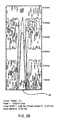
- FIG. 3 depicts an exemplary imaging assembly 50 according to the present invention.
- Imaging assembly 50 has a distal end 56 and a proximal end 57.
- Proximal end 57 is adapted to be operably attached to a drive cable (not shown).
- Exemplary drive cables are described in U.S. Patent Application Serial No. 09/017,578 . entitled "Integrated Coaxial Transmission Line and Flexible Drive Cable”. The drive cable rotates imaging assembly 50 during operation.
- Transducer element 54 is operably attached to distal end 56.
- Transducer element 54 may include a backing material (not shown) and one or more matching layers (not shown) operably attached to opposing surfaces of transducer element 54.
- Transducer element 54 is generally elliptical or oval shaped, and has a major axis 58 and a minor axis 60.
- transducer 54 projects ultrasound signals into a 360 degree image plane.
- the image plane has an in-plane or X-plane component 62 created primarily by the rotation of transducer 54.
- the image plane also has a cross-plane or Y-plane component 64 created primarily by the length of major axis 58 of transducer 54.
- transducer element 54 has a first radius of curvature (ROC) 68 along major axis 58, and a second ROC 66 along minor axis 60.
- ROC 68 is smaller than ROC 66.
- the radius of curvature along minor axis 60 is greater than the radius of curvature along major axis 58.
- major axis 58 has a tighter focus due to the smaller radius of curvature.
- ROC 68 is about 2.5 millimeters mm and ROC 66 is about 4.0 mm, although other ROCs may be used.
- transducer 54 has a focal length 70 for X-plane component 62 and a focal length 72 for Y-plane component 64.
- the focal length of a transducer element is a function of the transducer element size and the frequency of signals transmitted therefrom.
- Curving transducer element 54 provides a focusing effect.
- the focal length of transducer 54 in the cross-plane and in-plane can be generally equal notwithstanding the larger major axis length.
- the cross-plane and in-plane focal lengths are between about 0.25 mm and about 2.5 mm.
- the imaging profile in both the cross-plane and in-plane are similar to that depicted in Fig. 2A .
- FIG. 4 depicts an imaging assembly 100 with a transducer element 104 operably attached to a distal end 106 of the imaging assembly 100.
- Transducer element 104 has a major axis 108 and a minor axis 110.
- major axis 108 is about 0.74 mm (0.029 inches) and minor axis 110 is about 0.64 mm (0.025 inches), although other dimensions may be used within the scope of the present invention.
- Transducer element 104 has a generally flat outer face.
- Imaging assembly 100 is rotated by a drive cable (not shown) as previously discussed.
- transducer 104 projects ultrasound signals into a 360 degree image plane.
- the image plane has an in-plane or X-plane component 112 created primarily by the rotation of transducer 104, and a cross-plane or Y-plane component 114 created primarily by the length of minor axis 110.
- major axis 108 is aligned with in-plane 112
- minor axis 110 is aligned with cross-plane 114. Aligning the shorter, minor axis 110 of transducer 104 with the cross-plane compensates for at least some of the refractory effects of the sheath (not shown).
- assembly 100 produces a more symmetrical beam profile than that depicted in Fig. 2 .
- transducer 104 has a curved outer face.
- transducer 104 can have a relatively uniform radius of curvature throughout.
- this embodiment relies primarily on the coaxial alignment of minor axis 110 with the imaging assembly longitudinal axis to provide improved cross-plane resolution.
- the beam profile is narrowed in both the in-plane and cross-plane directions by having a curved transducer outer face with a relatively uniform radius of curvature, compared to transducer 104 having a flat outer face.
- transducer 104 has a radius of curvature profile similar to that described in conjunction with Fig. 3 .
- minor axis 110 has a tighter radius of curvature than the major axis 108 radius of curvature.
- the cross-plane component 114 of the image plane has improved resolution due to minor axis 110 being generally aligned with the imaging assembly 100 longitudinal axis, and also due to minor axis 110 having a tighter radius of curvature profile.
- Figs. 5A-5C depict a tapered focus transducer package 150.
- Transducer package 150 includes a transducer 152 having an outer face 154 and a second face 156. Outer face 154 and second face 156 are spaced apart to create a transducer thickness 158. As shown in Figs. 5A-5C , outer face 154 is curved relative to second face 156. As a result, transducer thickness 158 varies across the transducer. Transducers of this type show an increase in bandwidth as compared to similar transducers of uniform thickness.
- Figs. 5A-5C further include a matching layer 160 having a matching layer first face 162 and a matching layer second face 164. Matching layer second face 164 is operably attached to transducer outer face 154 using epoxy or the like.
- matching layer 160 has a generally uniform thickness. In this manner, matching layer first face 162 and matching layer second face 164 have a similar curvature to that of transducer outer face 154. Alternatively, and as shown in Fig. 5B , matching layer first face 162 is generally flat. As a result, matching layer 160 thickness varies, with matching layer 160 being thickest near the center. Due to the diminutive sizes of transducer 152 and matching layer 160 for imaging catheters, a variable thickness matching layer 160 will likely not have severe detrimental effects to imaging performance as a result of varying thickness across matching layer 160. Further, it may be easier to manufacture matching layer first face 162 to be flat. Another embodiment, as shown in Fig.
- matching layer 160 which is tapered and increases in thickness from the center of transducer element 152 towards the edge or periphery of transducer element 152 in the same fashion as the thickness of transducer element 152.
- the thickness of matching layer 160 varies in this embodiment so that the ratio of the matching layer 160 thickness to the thickness of transducer element 152 remains generally constant, or close to constant, throughout the transducer face 154.
- a true focus transducer package 170 can be used with the imaging assemblies of the present invention, including imaging assemblies 50, 100.
- transducer thickness 178 is generally uniform across transducer 172.
- Figs. 5D and 5E further include a matching layer 180 having a matching layer first face 182 and a matching layer second face 184. Matching layer second face 184 is operably attached to transducer outer face 174 using an epoxy or the like.
- matching layer 180 may have a uniform thickness (as shown in Fig. 5D ) or a variable thickness (as shown in Fig. 5E ).
- Matching layers 160, 180 may comprise a wide range of materials, and preferably have an acoustic impedance less than the acoustic impedance of transducer 162, 172, respectively. Such matching layers 160, 180 help facilitate acoustic coupling with the tissue or fluid to be imaged. Matching layers of the present invention also may include a thermoplastic.
- Catheter 200 includes an imaging assembly as previously described.
- Catheter 200 is depicted with imaging assembly 50, including transducer element 54 having a radius of curvature profile as previously described.
- imaging assembly 100 and other imaging assemblies, may be used with catheter 200 within the scope of the present invention.
- Imaging assembly 50 is operably attached to a drive cable 210 for rotation of imaging assembly 50.
- Imaging assembly 50 and drive cable 210 are disposed within a sheath 220.
- sheath 220 comprises polyethylene of high density, low density, combinations thereof, and the like.
- sheath 220 has an acoustic impedance similar to the surrounding tissue or fluids being imaged to reduce the effects of reflected signals off of sheath 220.
- Drive cable 210 rotates during operation of transducer 54, as shown by an arrow 230.
- Transducer 54 propagates ultrasound signals into an image plane having an in-plane component 62 and a cross-plane component 64. Due in part to transducer 54 having a tighter radius of curvature in the cross-plane direction, the cross-plane component 64 has improved lateral resolution compared to the assembly depicted in Figs. 1A-1B .
- catheter 200 includes imaging assembly 100 as described in conjunction with Fig. 4 .
- catheter 200 has improved cross-plane lateral resolution, compared to the assembly depicted in Figs. 1A-1B , due to the alignment of transducer 104 minor axis 110 with the longitudinal axis of catheter 200.
- transducer 104 By also providing transducer 104 with a tighter ROC in the cross-plane direction than in the in-plane direction, cross-plane lateral resolution is further improved.
- the use of imaging assembly 50 having transducer 54 with the desired radius of curvature profile results in a generally circular focal plane 250. More specifically, the tighter radius of curvature of transducer 54 in the cross-plane direction, and/or having the minor axis of the transducer being parallel to the longitudinal axis of the catheter, tightens the cross-plane ultrasound profile a sufficient amount so that the focal length in the cross-plane direction and the focal length in the in-plane direction are generally equal. As a result, a tighter and more uniform ultrasound beam profile is produced.
- Fig. 8 depicts still another embodiment of the present invention.
- Fig. 8 depicts an imaging catheter 80, ostensibly as described in conjunction with Figs. 6 and 7 , except catheter 80 has a transducer element 82 having a generally round outer face.
- transducer element 82 has a tighter radius of curvature in the cross-plane direction 84 than in the in-plane direction 86.
- the beam profile generated by transducer element 82 is narrowed in the cross-plane direction a sufficient amount to compensate for at least some of the beam profile widening effects of a sheath 88.
- catheter 80 produces a beam profile having a generally circularly cross sectional shape at a focal plane 90.
Abstract
Description
- The present invention relates generally to ultrasonic imaging catheters, and more particularly, to ultrasonic transducers providing improved resolution for such catheters.
- Intravascular imaging of blood vessels and surrounding tissues continues to be of great benefit in a wide range of medical fields.
US 4 572 201 discloses a probe that is inserted into a lumen of a patient and comprises an elliptical transducer at its tip. A particularly successful design for anintravascular imaging catheter 10 is shown inFigs. 1A and 1B .Catheter 10 employs arotatable imaging assembly 12 having adistal end 16 and a proximal end. Anultrasound transducer 14 is attached todistal end 16. The proximal end is operably attached to a flexible drive cable (not shown).Transducer 14 typically is elliptical in shape with a flat outer face. The transducer outer face has its major axis aligned with alongitudinal axis 20 of theimaging assembly 12. In other cases, thetransducer 14 is round in shape with a flat outer face as shown inFig. 1C . - During operation, a
flexible sheath 18 is inserted into a patient with the drive cable andimaging assembly 12 disposed withinsheath 18. Theimaging assembly 12 typically is rotated withinsheath 18 during transmission of ultrasound signals into the patient. During rotation ofimaging assembly 12, transducer 14 projects ultrasound signals into a 360 degree image plane. The image plane has an in-plane orX-plane component 22 created primarily by the rotation oftransducer 14. The image plane also has a cross-plane or Y-plane component 24 created primarily by the length of the major axis oftransducer 14 for the transducer shown inFig. 1B . Thetransducer element 14 is connected to electronics, typically maintained outside the patient's body, to produce a video image of at least a portion of the image plane by well-known techniques. - To produce images, it is desirable to have ultrasound signals transmitted by transducer 14 pass through
sheath 18 and reflect off of tissue or fluids. However, a portion of the ultrasound signals transmitted by thetransducer 14 typically are reflected by thesheath 18. Another portion of the ultrasound signals pass throughsheath 18, but are refracted bysheath 18 during passage. - Due at least in part to the sheath effects on the ultrasound signal and to the shape of the transducer, ultrasound signals typically have a different in-plane profile than a cross plane profile. The in-plane profile typically is narrower or tighter than the cross-plane profile. This can be seen by comparing
Fig. 2A (depicting an in-plane profile 26 for a round transducer) withFig. 2B (depicting across-plane profile 28 for a round transducer). Further, the in-plane profile 26 has a focal length that is shorter compared to the focal length in thecross-plane profile 28. As a result, thetransducer 14 has better lateral resolution in the in-plane direction 22 than in thecross-plane direction 24. - It is desirable, therefore, to produce a tighter beam profile in the cross-plane direction so that the focal point is closer to the transducer surface. Improved cross-plane lateral resolution will result. It is further desirable to provide a more circular or symmetrical cross-section for the ultrasound signal profile, so that lateral resolution is similar for both the in-plane and cross-plane.
- According to the invention, there is provided an ultrasound imaging assembly for an ultrasound imaging catheter, comprising: a housing having a distal end, a proximal end, and a longitudinal axis; and a transducer element having a curved outer face, said outer face having a first radius of curvature in a first plane extending along a first axis and a second radius of curvature in a second plane extending along a second axis; wherein said transducer element is operably attached to said distal end and said first axis is parallel to said longitudinal axis; said second radius of curvature being greater than said first radius of curvature.
- In one embodiment, the first axis is a major axis of the outer face and the second axis is a minor axis of the outer face. Alternatively, the first axis is a minor axis of the outer face and the second axis is a major axis of the outer face. In this manner, elliptical or oval transducers are used. Alternatively, the outer face is generally round.
- In still another embodiment, the transducer element further includes a second face spaced apart from the outer face to define a transducer thickness therebetween. In one embodiment, the second and outer faces are both curved so that the transducer thickness is generally uniform. Alternatively, the transducer thickness varies by having the outer face curved relative to the second face.
- In one embodiment, the imaging assembly further includes a matching layer having first and second faces defining a matching layer thickness therebetween. Matching layer second face is coupled to the transducer element outer face. In one embodiment, the matching layer thickness is generally uniform. Alternatively, the matching layer first face is generally flat so that the matching layer thickness varies. In one particular embodiment, the matching layer thickness increases from a center of the transducer element to a periphery of the transducer element.
- The transducer element may have a generally elliptical outer face.
- The present invention further provides ultrasound imaging catheters having an imaging assembly according to the invention and which include a drive cable coupled to the proximal end and a sheath into which the imaging assembly and drive cable are disposed. In one particular embodiment, the sheath includes polyethylene.
- Other features and advantages of the invention will appear from the following description in which the preferred embodiment has been set forth in detail in conjunction with the accompanying drawings.
-
-
Fig. 1A provides a side cross-sectional view of a prior art imaging catheter; -
Figs. 1B and 1C provide alternative side cross-sectional views of the prior-art imaging catheter ofFig. 1A . -
Figs. 2A-2B depict an in-plane profile and a cross-plane profile, respectively, of the imaging catheter shown inFigs. 1A and 1C . -
Fig. 3A depicts a top view of an exemplary imaging assembly according to the present invention; -
Figs. 3B-3C depict cross-sectional side and cross-sectional front views, respectively, of the transducer included in the embodiment shown inFig. 3A ; -
Fig. 4 depicts the top view of an alternative imaging assembly according to the present invention; -
Figs. 5A-5E depict alternative embodiments of a transducer and matching layer package for use in imaging assemblies of the present invention; and -
Figs. 6-8 depict exemplary imaging catheters according to the present invention. -
Fig. 3 depicts anexemplary imaging assembly 50 according to the present invention.Imaging assembly 50 has adistal end 56 and aproximal end 57.Proximal end 57 is adapted to be operably attached to a drive cable (not shown). Exemplary drive cables are described inU.S. Patent Application Serial No. 09/017,578 . entitled "Integrated Coaxial Transmission Line and Flexible Drive Cable". The drive cable rotatesimaging assembly 50 during operation. - A
transducer element 54 is operably attached todistal end 56.Transducer element 54 may include a backing material (not shown) and one or more matching layers (not shown) operably attached to opposing surfaces oftransducer element 54.Transducer element 54 is generally elliptical or oval shaped, and has amajor axis 58 and aminor axis 60. - During rotation of
imaging assembly 50,transducer 54 projects ultrasound signals into a 360 degree image plane. The image plane has an in-plane orX-plane component 62 created primarily by the rotation oftransducer 54. The image plane also has a cross-plane or Y-plane component 64 created primarily by the length ofmajor axis 58 oftransducer 54. - As shown in
Figs. 3B and 3C ,transducer element 54 has a first radius of curvature (ROC) 68 alongmajor axis 58, and asecond ROC 66 alongminor axis 60. As shown,ROC 68 is smaller thanROC 66. In other words, the radius of curvature alongminor axis 60 is greater than the radius of curvature alongmajor axis 58. As a result,major axis 58 has a tighter focus due to the smaller radius of curvature. In one particular arrangement,ROC 68 is about 2.5 millimeters mm andROC 66 is about 4.0 mm, although other ROCs may be used. - Similarly,
transducer 54 has afocal length 70 forX-plane component 62 and afocal length 72 for Y-plane component 64. Typically the focal length of a transducer element is a function of the transducer element size and the frequency of signals transmitted therefrom. Curvingtransducer element 54 provides a focusing effect. By having a tighter radius of curvature alongmajor axis 58, the focal length oftransducer 54 in the cross-plane and in-plane can be generally equal notwithstanding the larger major axis length. In one arrangement, the cross-plane and in-plane focal lengths are between about 0.25 mm and about 2.5 mm. As a result, the imaging profile in both the cross-plane and in-plane are similar to that depicted inFig. 2A . - Turning now to
Fig. 4 , another exemplary embodiment of the present invention will be described.Fig. 4 depicts animaging assembly 100 with atransducer element 104 operably attached to adistal end 106 of theimaging assembly 100.Transducer element 104 has amajor axis 108 and aminor axis 110. In one embodiment,major axis 108 is about 0.74 mm (0.029 inches) andminor axis 110 is about 0.64 mm (0.025 inches), although other dimensions may be used within the scope of the present invention.Transducer element 104 has a generally flat outer face. -
Imaging assembly 100 is rotated by a drive cable (not shown) as previously discussed. During rotation ofimaging assembly 100,transducer 104 projects ultrasound signals into a 360 degree image plane. The image plane has an in-plane orX-plane component 112 created primarily by the rotation oftransducer 104, and a cross-plane or Y-plane component 114 created primarily by the length ofminor axis 110. In this embodiment,major axis 108 is aligned with in-plane 112, andminor axis 110 is aligned withcross-plane 114. Aligning the shorter,minor axis 110 oftransducer 104 with the cross-plane compensates for at least some of the refractory effects of the sheath (not shown). As a result, ultrasound signals propagated intocross-plane 114 will have a tighter profile and a shorter focal length compared to those depicted inFig. 2B . Hence,assembly 100 produces a more symmetrical beam profile than that depicted inFig. 2 . - In another embodiment,
transducer 104 has a curved outer face. For example,transducer 104 can have a relatively uniform radius of curvature throughout. As with the embodiment described above with the flat transducer outer face, this embodiment relies primarily on the coaxial alignment ofminor axis 110 with the imaging assembly longitudinal axis to provide improved cross-plane resolution. Further, the beam profile is narrowed in both the in-plane and cross-plane directions by having a curved transducer outer face with a relatively uniform radius of curvature, compared totransducer 104 having a flat outer face. - In still another embodiment,
transducer 104 has a radius of curvature profile similar to that described in conjunction withFig. 3 . In this embodiment, however,minor axis 110 has a tighter radius of curvature than themajor axis 108 radius of curvature. In this manner, thecross-plane component 114 of the image plane has improved resolution due tominor axis 110 being generally aligned with theimaging assembly 100 longitudinal axis, and also due tominor axis 110 having a tighter radius of curvature profile. - Turning now to
Figs. 5A-5E , exemplary transducer elements and matching layers for use with the present invention will be described.Figs. 5A-5C depict a taperedfocus transducer package 150.Transducer package 150 includes atransducer 152 having anouter face 154 and asecond face 156.Outer face 154 andsecond face 156 are spaced apart to create atransducer thickness 158. As shown inFigs. 5A-5C ,outer face 154 is curved relative tosecond face 156. As a result,transducer thickness 158 varies across the transducer. Transducers of this type show an increase in bandwidth as compared to similar transducers of uniform thickness.Figs. 5A-5C further include amatching layer 160 having a matching layerfirst face 162 and a matching layersecond face 164. Matching layersecond face 164 is operably attached to transducerouter face 154 using epoxy or the like. - In the embodiment shown in
Fig. 5A , matchinglayer 160 has a generally uniform thickness. In this manner, matching layerfirst face 162 and matching layersecond face 164 have a similar curvature to that of transducerouter face 154. Alternatively, and as shown inFig. 5B , matching layerfirst face 162 is generally flat. As a result,matching layer 160 thickness varies, withmatching layer 160 being thickest near the center. Due to the diminutive sizes oftransducer 152 andmatching layer 160 for imaging catheters, a variablethickness matching layer 160 will likely not have severe detrimental effects to imaging performance as a result of varying thickness acrossmatching layer 160. Further, it may be easier to manufacture matching layerfirst face 162 to be flat. Another embodiment, as shown inFig. 5C , has matchinglayer 160 which is tapered and increases in thickness from the center oftransducer element 152 towards the edge or periphery oftransducer element 152 in the same fashion as the thickness oftransducer element 152. The thickness ofmatching layer 160 varies in this embodiment so that the ratio of thematching layer 160 thickness to the thickness oftransducer element 152 remains generally constant, or close to constant, throughout thetransducer face 154. - As shown in
Figs. 5D-5E , a truefocus transducer package 170 can be used with the imaging assemblies of the present invention, includingimaging assemblies Figs. 5D-5E depict atrue focus transducer 172 having anouter face 174 and asecond face 176.Faces transducer thickness 178. For truefocus transducer package 170,transducer thickness 178 is generally uniform acrosstransducer 172.Figs. 5D and 5E further include amatching layer 180 having a matching layerfirst face 182 and a matching layersecond face 184. Matching layersecond face 184 is operably attached to transducerouter face 174 using an epoxy or the like. Again, matchinglayer 180 may have a uniform thickness (as shown inFig. 5D ) or a variable thickness (as shown inFig. 5E ). - Matching layers 160, 180 may comprise a wide range of materials, and preferably have an acoustic impedance less than the acoustic impedance of
transducer - Turning now to
Fig. 6 , anexemplary imaging catheter 200 according to the present invention will be described.Catheter 200 includes an imaging assembly as previously described.Catheter 200 is depicted withimaging assembly 50, includingtransducer element 54 having a radius of curvature profile as previously described. However, it will be appreciated by those skilled in the art thatimaging assembly 100, and other imaging assemblies, may be used withcatheter 200 within the scope of the present invention. -
Imaging assembly 50, as described hereinbefore in greater detail, is operably attached to adrive cable 210 for rotation ofimaging assembly 50.Imaging assembly 50 and drivecable 210 are disposed within asheath 220. In one embodiment,sheath 220 comprises polyethylene of high density, low density, combinations thereof, and the like. Preferably,sheath 220 has an acoustic impedance similar to the surrounding tissue or fluids being imaged to reduce the effects of reflected signals off ofsheath 220.Drive cable 210 rotates during operation oftransducer 54, as shown by anarrow 230.Transducer 54 propagates ultrasound signals into an image plane having an in-plane component 62 and across-plane component 64. Due in part totransducer 54 having a tighter radius of curvature in the cross-plane direction, thecross-plane component 64 has improved lateral resolution compared to the assembly depicted inFigs. 1A-1B . - Alternatively, in another embodiment,
catheter 200 includesimaging assembly 100 as described in conjunction withFig. 4 . In this manner,catheter 200 has improved cross-plane lateral resolution, compared to the assembly depicted inFigs. 1A-1B , due to the alignment oftransducer 104minor axis 110 with the longitudinal axis ofcatheter 200. By also providingtransducer 104 with a tighter ROC in the cross-plane direction than in the in-plane direction, cross-plane lateral resolution is further improved. - As shown in
Fig. 7 , the use ofimaging assembly 50 havingtransducer 54 with the desired radius of curvature profile results in a generally circularfocal plane 250. More specifically, the tighter radius of curvature oftransducer 54 in the cross-plane direction, and/or having the minor axis of the transducer being parallel to the longitudinal axis of the catheter, tightens the cross-plane ultrasound profile a sufficient amount so that the focal length in the cross-plane direction and the focal length in the in-plane direction are generally equal. As a result, a tighter and more uniform ultrasound beam profile is produced. -
Fig. 8 depicts still another embodiment of the present invention.Fig. 8 depicts animaging catheter 80, ostensibly as described in conjunction withFigs. 6 and7 , exceptcatheter 80 has atransducer element 82 having a generally round outer face. In this arrangement,transducer element 82 has a tighter radius of curvature in thecross-plane direction 84 than in the in-plane direction 86. The beam profile generated bytransducer element 82 is narrowed in the cross-plane direction a sufficient amount to compensate for at least some of the beam profile widening effects of asheath 88. In this manner,catheter 80 produces a beam profile having a generally circularly cross sectional shape at afocal plane 90. - The invention has now been described in detail. However, it will be appreciated that certain changes and modifications may be made. For example, the above description involves single transducer element imaging assemblies when the present invention is not so limited. Those skilled in the art will recognize that imaging assemblies having multiple transducer elements, including annular arrays, are within the scope of the present invention. Exemplary annular arrays are described in
U.S. Patent Application Serial No. 09/017,581 . Therefore, the scope and content of this invention are not limited by the foregoing description. Rather, the scope is defined by the following claims.
Claims (14)
- An ultrasound imaging assembly (50) for an ultrasound imaging catheter, comprising:a housing having a distal end (56), a proximal end (57), and a longitudinal axis; anda transducer element (54) having a curved outer face, said outer face having a first radius of curvature (68) in a first plane extending along a first axis (58) and a second radius of curvature (66) in a second plane extending along a second axis (60);wherein said transducer (54) element is operably attached to said distal end (56) and said first axis is parallel to said longitudinal axis;characterized in thatsaid second radius of curvature (66) is greater than said first radius of curvature (68).
- An imaging assembly as in claim 1, wherein said first axis (58) is a major axis of said outer face and said second axis (60) is a minor axis of said outer face.
- An imaging assembly as in claim 1, wherein said first axis (58) is a minor axis of said outer face and said second axis (60) is a major axis of said outer face.
- An imaging assembly as in claim 1, wherein said outer face is generally round.
- An imaging assembly as in claim 1, wherein said transducer element (54) further comprises a second face spaced apart from said outer face, said outer face and second face defining a transducer thickness therebetween.
- An imaging assembly as in claim 5, wherein said outer face and said second face are both curved so that said transducer thickness is generally uniform.
- An imaging assembly as in claim 5, wherein said outer face is curved relative to said second face so that said transducer thickness varies.
- An imaging assembly as in claim 1, further comprising a matching layer (160) having first and second faces (162;164) defining a matching layer thickness therebetween, said matching layer second face being coupled to said transducer element outer face.
- An imaging assembly as in claim 8, wherein said matching layer first face (162) is generally flat so that said matching layer thickness varies.
- An imaging assembly as in claim 8, wherein said matching layer first face (162) is curved so that said matching layer thickness is generally uniform.
- An imaging assembly as in claim 8, wherein said matching layer is concave and said matching layer thickness increases from a center of said transducer element towards a periphery of said transducer element.
- An ultrasound imaging assembly as in claim 1 wherein said transducer element has an elliptical outer face.
- An ultrasound imaging catheter (200) comprising:an ultrasound imaging assembly (50; 100) according to any preceding claim;a drive cable (210) coupled to said proximal end (57); anda sheath (220) into which said imaging assembly (50; 100) and drive cable (210) are disposed.
- An imaging catheter as in claim 13, wherein said sheath comprises polyethylene.
Applications Claiming Priority (2)
| Application Number | Priority Date | Filing Date | Title |
|---|---|---|---|
| US09/362,630 US6287261B1 (en) | 1999-07-21 | 1999-07-21 | Focused ultrasound transducers and systems |
| EP00942333A EP1196091B1 (en) | 1999-07-21 | 2000-07-20 | Focused ultrasound transducers and systems |
Related Parent Applications (1)
| Application Number | Title | Priority Date | Filing Date |
|---|---|---|---|
| EP00942333A Division EP1196091B1 (en) | 1999-07-21 | 2000-07-20 | Focused ultrasound transducers and systems |
Publications (4)
| Publication Number | Publication Date |
|---|---|
| EP1723910A2 EP1723910A2 (en) | 2006-11-22 |
| EP1723910A3 EP1723910A3 (en) | 2007-07-18 |
| EP1723910A8 EP1723910A8 (en) | 2008-10-15 |
| EP1723910B1 true EP1723910B1 (en) | 2009-03-04 |
Family
ID=23426880
Family Applications (2)
| Application Number | Title | Priority Date | Filing Date |
|---|---|---|---|
| EP00942333A Expired - Lifetime EP1196091B1 (en) | 1999-07-21 | 2000-07-20 | Focused ultrasound transducers and systems |
| EP06076470A Expired - Lifetime EP1723910B1 (en) | 1999-07-21 | 2000-07-20 | Focused ultrasound transducers and systems |
Family Applications Before (1)
| Application Number | Title | Priority Date | Filing Date |
|---|---|---|---|
| EP00942333A Expired - Lifetime EP1196091B1 (en) | 1999-07-21 | 2000-07-20 | Focused ultrasound transducers and systems |
Country Status (8)
| Country | Link |
|---|---|
| US (1) | US6287261B1 (en) |
| EP (2) | EP1196091B1 (en) |
| JP (1) | JP4659313B2 (en) |
| AT (2) | ATE424146T1 (en) |
| CA (1) | CA2378049A1 (en) |
| DE (2) | DE60041724D1 (en) |
| ES (2) | ES2323383T3 (en) |
| WO (1) | WO2001005305A1 (en) |
Families Citing this family (13)
| Publication number | Priority date | Publication date | Assignee | Title |
|---|---|---|---|---|
| US6161543A (en) | 1993-02-22 | 2000-12-19 | Epicor, Inc. | Methods of epicardial ablation for creating a lesion around the pulmonary veins |
| US6805128B1 (en) | 1996-10-22 | 2004-10-19 | Epicor Medical, Inc. | Apparatus and method for ablating tissue |
| US7052493B2 (en) | 1996-10-22 | 2006-05-30 | Epicor Medical, Inc. | Methods and devices for ablation |
| US6311692B1 (en) | 1996-10-22 | 2001-11-06 | Epicor, Inc. | Apparatus and method for diagnosis and therapy of electrophysiological disease |
| US6719755B2 (en) | 1996-10-22 | 2004-04-13 | Epicor Medical, Inc. | Methods and devices for ablation |
| US8709007B2 (en) | 1997-10-15 | 2014-04-29 | St. Jude Medical, Atrial Fibrillation Division, Inc. | Devices and methods for ablating cardiac tissue |
| US8308719B2 (en) | 1998-09-21 | 2012-11-13 | St. Jude Medical, Atrial Fibrillation Division, Inc. | Apparatus and method for ablating tissue |
| WO2001005306A1 (en) | 1999-07-19 | 2001-01-25 | Epicor, Inc. | Apparatus and method for ablating tissue |
| US7909766B2 (en) * | 2003-05-21 | 2011-03-22 | Scimed Life Systems, Inc. | Systems and methods for improving the imaging resolution of an imaging transducer |
| FR2866801B1 (en) * | 2004-02-27 | 2006-12-01 | Quantel Medical | SECTORAL SCANNING ECHOGRAPHIC PROBE USING A TRANSDUCER FUTURE TO COME IN CONTACT WITH THE STRUCTURE TO BE EXAMINED |
| US8932208B2 (en) | 2005-05-26 | 2015-01-13 | Maquet Cardiovascular Llc | Apparatus and methods for performing minimally-invasive surgical procedures |
| WO2009045265A1 (en) | 2007-10-05 | 2009-04-09 | Maquet Cardiovascular, Llc | Devices and methods for minimally-invasive surgical procedures |
| JP5265823B1 (en) * | 2011-10-27 | 2013-08-14 | オリンパスメディカルシステムズ株式会社 | Ultrasonic observation equipment |
Family Cites Families (13)
| Publication number | Priority date | Publication date | Assignee | Title |
|---|---|---|---|---|
| US3958559A (en) | 1974-10-16 | 1976-05-25 | New York Institute Of Technology | Ultrasonic transducer |
| US4246791A (en) * | 1978-03-27 | 1981-01-27 | New York Institute Of Technology | Ultrasonic imaging apparatus |
| US4248090A (en) * | 1978-03-27 | 1981-02-03 | New York Institute Of Technology | Apparatus for ultrasonically imaging a body |
| US4325381A (en) * | 1979-11-21 | 1982-04-20 | New York Institute Of Technology | Ultrasonic scanning head with reduced geometrical distortion |
| JPS6080441A (en) * | 1983-10-11 | 1985-05-08 | 株式会社日立製作所 | Ultrasonic probe for scanning body cavity |
| DE3441684A1 (en) | 1984-11-15 | 1986-05-15 | SWF Auto-Electric GmbH, 7120 Bietigheim-Bissingen | Electro-acoustic transducer |
| JPH074376B2 (en) * | 1986-11-13 | 1995-01-25 | オリンパス光学工業株式会社 | Intracorporeal ultrasound diagnostic device |
| US4762002A (en) * | 1986-11-26 | 1988-08-09 | Picker International, Inc. | Probe array for ultrasonic imaging |
| US5520189A (en) * | 1990-07-13 | 1996-05-28 | Coraje, Inc. | Intravascular ultrasound imaging guidewire |
| JPH0630940A (en) * | 1992-07-10 | 1994-02-08 | Olympus Optical Co Ltd | Ultrasonic probe |
| JPH06285106A (en) * | 1993-03-30 | 1994-10-11 | Shimadzu Corp | Ultrasonic therapeutic device |
| JPH07184898A (en) * | 1993-12-28 | 1995-07-25 | Olympus Optical Co Ltd | Ultrasonic probe |
| US5640961A (en) * | 1995-09-25 | 1997-06-24 | Hewlett-Packard Company | Device with aspherical compensation for focusing ultrasound |
-
1999
- 1999-07-21 US US09/362,630 patent/US6287261B1/en not_active Expired - Lifetime
-
2000
- 2000-07-20 AT AT06076470T patent/ATE424146T1/en not_active IP Right Cessation
- 2000-07-20 ES ES06076470T patent/ES2323383T3/en not_active Expired - Lifetime
- 2000-07-20 EP EP00942333A patent/EP1196091B1/en not_active Expired - Lifetime
- 2000-07-20 WO PCT/IB2000/001001 patent/WO2001005305A1/en active IP Right Grant
- 2000-07-20 AT AT00942333T patent/ATE369793T1/en not_active IP Right Cessation
- 2000-07-20 JP JP2001510368A patent/JP4659313B2/en not_active Expired - Lifetime
- 2000-07-20 CA CA002378049A patent/CA2378049A1/en not_active Abandoned
- 2000-07-20 ES ES00942333T patent/ES2291216T3/en not_active Expired - Lifetime
- 2000-07-20 EP EP06076470A patent/EP1723910B1/en not_active Expired - Lifetime
- 2000-07-20 DE DE60041724T patent/DE60041724D1/en not_active Expired - Lifetime
- 2000-07-20 DE DE60035995T patent/DE60035995T2/en not_active Expired - Lifetime
Also Published As
| Publication number | Publication date |
|---|---|
| ATE369793T1 (en) | 2007-09-15 |
| EP1723910A2 (en) | 2006-11-22 |
| JP2003504143A (en) | 2003-02-04 |
| ES2291216T3 (en) | 2008-03-01 |
| EP1196091A1 (en) | 2002-04-17 |
| US6287261B1 (en) | 2001-09-11 |
| EP1723910A3 (en) | 2007-07-18 |
| ES2323383T3 (en) | 2009-07-14 |
| CA2378049A1 (en) | 2001-01-25 |
| ATE424146T1 (en) | 2009-03-15 |
| DE60035995T2 (en) | 2008-05-08 |
| EP1196091B1 (en) | 2007-08-15 |
| JP4659313B2 (en) | 2011-03-30 |
| EP1723910A8 (en) | 2008-10-15 |
| DE60035995D1 (en) | 2007-09-27 |
| DE60041724D1 (en) | 2009-04-16 |
| WO2001005305A1 (en) | 2001-01-25 |
Similar Documents
| Publication | Publication Date | Title |
|---|---|---|
| EP1723910B1 (en) | Focused ultrasound transducers and systems | |
| US5622175A (en) | Miniaturization of a rotatable sensor | |
| US5846205A (en) | Catheter-mounted, phased-array ultrasound transducer with improved imaging | |
| EP1534140B1 (en) | Ultrasound array transducer for catheter use | |
| US6860856B2 (en) | Echogenic surface for enhanced ultasonic visibility | |
| US6733456B1 (en) | Off-aperture electrical connection for ultrasonic transducer | |
| US20080269615A1 (en) | Transducer with multiple resonant frequencies for an imaging catheter | |
| US7245959B1 (en) | Imaging catheter for use inside a guiding catheter | |
| US6358211B1 (en) | Ultrasound lucent apparatus and methods of using | |
| WO1998008440A1 (en) | Flexible directive ultrasonically marked catheter | |
| JP2004537903A (en) | Acoustic imaging system with out-of-focus lens | |
| US6406433B1 (en) | Off-aperture electrical connect transducer and methods of making | |
| WO2000025297A3 (en) | Ultrasonic transducer having a tilted support, and method of manufacture | |
| JP3889869B2 (en) | Ultrasonic probe | |
| US7909766B2 (en) | Systems and methods for improving the imaging resolution of an imaging transducer | |
| CN117426790A (en) | Ultrasonic probe and ultrasonic diagnostic apparatus |
Legal Events
| Date | Code | Title | Description |
|---|---|---|---|
| PUAI | Public reference made under article 153(3) epc to a published international application that has entered the european phase |
Free format text: ORIGINAL CODE: 0009012 |
|
| AC | Divisional application: reference to earlier application |
Ref document number: 1196091 Country of ref document: EP Kind code of ref document: P |
|
| AK | Designated contracting states |
Kind code of ref document: A2 Designated state(s): AT BE CH CY DE DK ES FI FR GB GR IE IT LI LU MC NL PT SE |
|
| PUAL | Search report despatched |
Free format text: ORIGINAL CODE: 0009013 |
|
| AK | Designated contracting states |
Kind code of ref document: A3 Designated state(s): AT BE CH CY DE DK ES FI FR GB GR IE IT LI LU MC NL PT SE |
|
| 17P | Request for examination filed |
Effective date: 20070926 |
|
| 17Q | First examination report despatched |
Effective date: 20071120 |
|
| AKX | Designation fees paid |
Designated state(s): AT BE CH CY DE DK ES FI FR GB GR IE IT LI LU MC NL PT SE |
|
| R17C | First examination report despatched (corrected) |
Effective date: 20080625 |
|
| GRAP | Despatch of communication of intention to grant a patent |
Free format text: ORIGINAL CODE: EPIDOSNIGR1 |
|
| GRAS | Grant fee paid |
Free format text: ORIGINAL CODE: EPIDOSNIGR3 |
|
| GRAA | (expected) grant |
Free format text: ORIGINAL CODE: 0009210 |
|
| AC | Divisional application: reference to earlier application |
Ref document number: 1196091 Country of ref document: EP Kind code of ref document: P |
|
| AK | Designated contracting states |
Kind code of ref document: B1 Designated state(s): AT BE CH CY DE DK ES FI FR GB GR IE IT LI LU MC NL PT SE |
|
| REG | Reference to a national code |
Ref country code: GB Ref legal event code: FG4D |
|
| REG | Reference to a national code |
Ref country code: CH Ref legal event code: EP |
|
| REG | Reference to a national code |
Ref country code: IE Ref legal event code: FG4D |
|
| REF | Corresponds to: |
Ref document number: 60041724 Country of ref document: DE Date of ref document: 20090416 Kind code of ref document: P |
|
| REG | Reference to a national code |
Ref country code: ES Ref legal event code: FG2A Ref document number: 2323383 Country of ref document: ES Kind code of ref document: T3 |
|
| PG25 | Lapsed in a contracting state [announced via postgrant information from national office to epo] |
Ref country code: FI Free format text: LAPSE BECAUSE OF FAILURE TO SUBMIT A TRANSLATION OF THE DESCRIPTION OR TO PAY THE FEE WITHIN THE PRESCRIBED TIME-LIMIT Effective date: 20090304 |
|
| PG25 | Lapsed in a contracting state [announced via postgrant information from national office to epo] |
Ref country code: AT Free format text: LAPSE BECAUSE OF FAILURE TO SUBMIT A TRANSLATION OF THE DESCRIPTION OR TO PAY THE FEE WITHIN THE PRESCRIBED TIME-LIMIT Effective date: 20090304 Ref country code: SE Free format text: LAPSE BECAUSE OF FAILURE TO SUBMIT A TRANSLATION OF THE DESCRIPTION OR TO PAY THE FEE WITHIN THE PRESCRIBED TIME-LIMIT Effective date: 20090604 |
|
| PG25 | Lapsed in a contracting state [announced via postgrant information from national office to epo] |
Ref country code: BE Free format text: LAPSE BECAUSE OF FAILURE TO SUBMIT A TRANSLATION OF THE DESCRIPTION OR TO PAY THE FEE WITHIN THE PRESCRIBED TIME-LIMIT Effective date: 20090304 |
|
| PG25 | Lapsed in a contracting state [announced via postgrant information from national office to epo] |
Ref country code: PT Free format text: LAPSE BECAUSE OF FAILURE TO SUBMIT A TRANSLATION OF THE DESCRIPTION OR TO PAY THE FEE WITHIN THE PRESCRIBED TIME-LIMIT Effective date: 20090818 |
|
| PLBE | No opposition filed within time limit |
Free format text: ORIGINAL CODE: 0009261 |
|
| STAA | Information on the status of an ep patent application or granted ep patent |
Free format text: STATUS: NO OPPOSITION FILED WITHIN TIME LIMIT |
|
| PG25 | Lapsed in a contracting state [announced via postgrant information from national office to epo] |
Ref country code: DK Free format text: LAPSE BECAUSE OF FAILURE TO SUBMIT A TRANSLATION OF THE DESCRIPTION OR TO PAY THE FEE WITHIN THE PRESCRIBED TIME-LIMIT Effective date: 20090304 |
|
| 26N | No opposition filed |
Effective date: 20091207 |
|
| PG25 | Lapsed in a contracting state [announced via postgrant information from national office to epo] |
Ref country code: MC Free format text: LAPSE BECAUSE OF NON-PAYMENT OF DUE FEES Effective date: 20090731 |
|
| REG | Reference to a national code |
Ref country code: CH Ref legal event code: PL |
|
| PG25 | Lapsed in a contracting state [announced via postgrant information from national office to epo] |
Ref country code: LI Free format text: LAPSE BECAUSE OF NON-PAYMENT OF DUE FEES Effective date: 20090731 Ref country code: CH Free format text: LAPSE BECAUSE OF NON-PAYMENT OF DUE FEES Effective date: 20090731 |
|
| PG25 | Lapsed in a contracting state [announced via postgrant information from national office to epo] |
Ref country code: IE Free format text: LAPSE BECAUSE OF NON-PAYMENT OF DUE FEES Effective date: 20090720 |
|
| PG25 | Lapsed in a contracting state [announced via postgrant information from national office to epo] |
Ref country code: GR Free format text: LAPSE BECAUSE OF FAILURE TO SUBMIT A TRANSLATION OF THE DESCRIPTION OR TO PAY THE FEE WITHIN THE PRESCRIBED TIME-LIMIT Effective date: 20090605 |
|
| PGFP | Annual fee paid to national office [announced via postgrant information from national office to epo] |
Ref country code: ES Payment date: 20100714 Year of fee payment: 11 |
|
| PGFP | Annual fee paid to national office [announced via postgrant information from national office to epo] |
Ref country code: FR Payment date: 20100813 Year of fee payment: 11 Ref country code: GB Payment date: 20100616 Year of fee payment: 11 Ref country code: IT Payment date: 20100722 Year of fee payment: 11 |
|
| PG25 | Lapsed in a contracting state [announced via postgrant information from national office to epo] |
Ref country code: LU Free format text: LAPSE BECAUSE OF NON-PAYMENT OF DUE FEES Effective date: 20090720 |
|
| PG25 | Lapsed in a contracting state [announced via postgrant information from national office to epo] |
Ref country code: CY Free format text: LAPSE BECAUSE OF FAILURE TO SUBMIT A TRANSLATION OF THE DESCRIPTION OR TO PAY THE FEE WITHIN THE PRESCRIBED TIME-LIMIT Effective date: 20090304 |
|
| PGFP | Annual fee paid to national office [announced via postgrant information from national office to epo] |
Ref country code: NL Payment date: 20110721 Year of fee payment: 12 |
|
| GBPC | Gb: european patent ceased through non-payment of renewal fee |
Effective date: 20110720 |
|
| REG | Reference to a national code |
Ref country code: FR Ref legal event code: ST Effective date: 20120330 |
|
| PG25 | Lapsed in a contracting state [announced via postgrant information from national office to epo] |
Ref country code: FR Free format text: LAPSE BECAUSE OF NON-PAYMENT OF DUE FEES Effective date: 20110801 |
|
| PG25 | Lapsed in a contracting state [announced via postgrant information from national office to epo] |
Ref country code: IT Free format text: LAPSE BECAUSE OF NON-PAYMENT OF DUE FEES Effective date: 20110720 |
|
| PG25 | Lapsed in a contracting state [announced via postgrant information from national office to epo] |
Ref country code: GB Free format text: LAPSE BECAUSE OF NON-PAYMENT OF DUE FEES Effective date: 20110720 |
|
| REG | Reference to a national code |
Ref country code: NL Ref legal event code: V1 Effective date: 20130201 |
|
| PG25 | Lapsed in a contracting state [announced via postgrant information from national office to epo] |
Ref country code: NL Free format text: LAPSE BECAUSE OF NON-PAYMENT OF DUE FEES Effective date: 20130201 |
|
| REG | Reference to a national code |
Ref country code: ES Ref legal event code: FD2A Effective date: 20130823 |
|
| PG25 | Lapsed in a contracting state [announced via postgrant information from national office to epo] |
Ref country code: ES Free format text: LAPSE BECAUSE OF NON-PAYMENT OF DUE FEES Effective date: 20110721 |
|
| PGFP | Annual fee paid to national office [announced via postgrant information from national office to epo] |
Ref country code: DE Payment date: 20140716 Year of fee payment: 15 |
|
| REG | Reference to a national code |
Ref country code: DE Ref legal event code: R119 Ref document number: 60041724 Country of ref document: DE |
|
| PG25 | Lapsed in a contracting state [announced via postgrant information from national office to epo] |
Ref country code: DE Free format text: LAPSE BECAUSE OF NON-PAYMENT OF DUE FEES Effective date: 20160202 |