EP1723900A1 - Ophthalmic measuring method and apparatus - Google Patents
Ophthalmic measuring method and apparatus Download PDFInfo
- Publication number
- EP1723900A1 EP1723900A1 EP06009876A EP06009876A EP1723900A1 EP 1723900 A1 EP1723900 A1 EP 1723900A1 EP 06009876 A EP06009876 A EP 06009876A EP 06009876 A EP06009876 A EP 06009876A EP 1723900 A1 EP1723900 A1 EP 1723900A1
- Authority
- EP
- European Patent Office
- Prior art keywords
- eye
- subject
- lachrymal fluid
- images
- target substance
- Prior art date
- Legal status (The legal status is an assumption and is not a legal conclusion. Google has not performed a legal analysis and makes no representation as to the accuracy of the status listed.)
- Granted
Links
Images


Classifications
-
- A—HUMAN NECESSITIES
- A61—MEDICAL OR VETERINARY SCIENCE; HYGIENE
- A61B—DIAGNOSIS; SURGERY; IDENTIFICATION
- A61B3/00—Apparatus for testing the eyes; Instruments for examining the eyes
- A61B3/10—Objective types, i.e. instruments for examining the eyes independent of the patients' perceptions or reactions
- A61B3/101—Objective types, i.e. instruments for examining the eyes independent of the patients' perceptions or reactions for examining the tear film
-
- A—HUMAN NECESSITIES
- A61—MEDICAL OR VETERINARY SCIENCE; HYGIENE
- A61B—DIAGNOSIS; SURGERY; IDENTIFICATION
- A61B3/00—Apparatus for testing the eyes; Instruments for examining the eyes
- A61B3/10—Objective types, i.e. instruments for examining the eyes independent of the patients' perceptions or reactions
-
- A—HUMAN NECESSITIES
- A61—MEDICAL OR VETERINARY SCIENCE; HYGIENE
- A61B—DIAGNOSIS; SURGERY; IDENTIFICATION
- A61B3/00—Apparatus for testing the eyes; Instruments for examining the eyes
- A61B3/10—Objective types, i.e. instruments for examining the eyes independent of the patients' perceptions or reactions
- A61B3/14—Arrangements specially adapted for eye photography
-
- A—HUMAN NECESSITIES
- A61—MEDICAL OR VETERINARY SCIENCE; HYGIENE
- A61B—DIAGNOSIS; SURGERY; IDENTIFICATION
- A61B5/00—Measuring for diagnostic purposes; Identification of persons
- A61B5/0059—Measuring for diagnostic purposes; Identification of persons using light, e.g. diagnosis by transillumination, diascopy, fluorescence
- A61B5/0071—Measuring for diagnostic purposes; Identification of persons using light, e.g. diagnosis by transillumination, diascopy, fluorescence by measuring fluorescence emission
-
- G—PHYSICS
- G06—COMPUTING OR CALCULATING; COUNTING
- G06T—IMAGE DATA PROCESSING OR GENERATION, IN GENERAL
- G06T7/00—Image analysis
- G06T7/0002—Inspection of images, e.g. flaw detection
- G06T7/0012—Biomedical image inspection
- G06T7/0014—Biomedical image inspection using an image reference approach
-
- A—HUMAN NECESSITIES
- A61—MEDICAL OR VETERINARY SCIENCE; HYGIENE
- A61B—DIAGNOSIS; SURGERY; IDENTIFICATION
- A61B2576/00—Medical imaging apparatus involving image processing or analysis
- A61B2576/02—Medical imaging apparatus involving image processing or analysis specially adapted for a particular organ or body part
-
- A—HUMAN NECESSITIES
- A61—MEDICAL OR VETERINARY SCIENCE; HYGIENE
- A61M—DEVICES FOR INTRODUCING MEDIA INTO, OR ONTO, THE BODY; DEVICES FOR TRANSDUCING BODY MEDIA OR FOR TAKING MEDIA FROM THE BODY; DEVICES FOR PRODUCING OR ENDING SLEEP OR STUPOR
- A61M2210/00—Anatomical parts of the body
- A61M2210/06—Head
- A61M2210/0612—Eyes
-
- G—PHYSICS
- G06—COMPUTING OR CALCULATING; COUNTING
- G06T—IMAGE DATA PROCESSING OR GENERATION, IN GENERAL
- G06T2207/00—Indexing scheme for image analysis or image enhancement
- G06T2207/30—Subject of image; Context of image processing
- G06T2207/30004—Biomedical image processing
- G06T2207/30041—Eye; Retina; Ophthalmic
Definitions
- the present invention relates to an ophthalmic measuring method and apparatus that can be used to screen dry eye and evaluate dry eye severity in a subject's eye.
- Embodiments of known techniques include a technique (see Japanese Laid-open Patent Application Publication No. 1997-201334 ) for capturing an image of an interference pattern formed in the lachrymal fluid surface layer of a subject's eye, and evaluating dry eye conditions based on the hue of a plurality of areas in the image of the interference pattern; and a technique (see Japanese Laid-open Patent Application Publication No.
- 1999-267102 for projecting an image of an aperture having a prescribed shape onto the surface of lachrymal fluid accumulated in the lachrymal fluid meniscus along the lower eyelid, capturing an image of the aperture projected on the lachrymal fluid surface, finding the curvature radius of the lachrymal fluid surface from the magnification factor of the aperture image, and evaluating dry eye severity.
- an object of the present invention is to ensure that the movement speed of lachrymal fluid can be reliably measured, diagnosis can be quantitatively performed from the movement speed of the lachrymal fluid thus measured even on a severely dry eye, and the state of a normal eye can be reliably identified.
- the present invention provides an ophthalmic measuring method comprising the steps of administering a target substance to the lachrymal fluid of a subject's eye; irradiating the lachrymal fluid with illuminating light; electronically capturing a plurality of images of the illuminated lachrymal fluid of the subject's eye, the images being captured respectively at different times; measuring the movement speed of the target substance based on the positions thereof in the images selected among the plurality of captured images and the capturing times of the selected images; and outputting the measured movement speed of the target substance as the movement speed of the lachrymal fluid of the subject's eye.
- the present invention also provides an ophthalmic measuring apparatus comprising means for electronically capturing an image of the lachrymal fluid layer in a prescribed position of a subject's eye to which a target substance is administered; means for selecting images among a plurality of images captured; means for computing the movement speed of the target substance based on the positions thereof in the selected images and the capturing times of the selected images; and means for outputting the computed movement speed of the target substance as the movement speed of the lachrymal fluid of the subject's eye.
- an image of the lachrymal fluid layer in a specific position of the subject's eye to which a target substance is administered is electronically captured a plurality of times, the image signal captured each time is computed and comparatively analyzed, and the movement speed of the target substance is measured as the movement speed of the lachrymal fluid of the subject's eye.
- the severity of dry eye is thus quantitatively evaluated based on the results of measuring the movement speed of the lachrymal fluid of the subject's eye.
- a target substance is administered to the subject's eye and its movement in the lachrymal fluid can be monitored even when an interference color does not occur. Therefore, the movement speed of lachrymal fluid can be quantified regardless of the state of the subject's eye, and there is no occurrence of the drawback of the prior art in which it was difficult to distinguish between a normal eye and a severely dry eye.
- FIG. 1 shows the simplified structure of an ophthalmic measuring apparatus according to the present invention.
- the reference numeral 1 indicates a white light source composed of a halogen lamp or the like for illuminating a subject's eye E.
- Light radiated from the white light source 1 passes through a mask 2 for limiting the field of illumination, and then illuminates a prescribed point P on the subject's eye E via a lens 3, an exciter filter 3a, a half mirror 4, and a lens 5.
- the position selected for this prescribed point P is the lipid layer of the outermost lachrymal fluid layer on the cornea of the subject's eye E.
- the intensity of the white light source 1 can be adjusted by a dimmer circuit (not shown in the drawing).
- the light reflected from point P enters a color CCD camera 7 via the lens 5, the half mirror 4, and a lens 6, and the RGB (color) video signal thus captured is inputted to an image processing device 20.
- the image processing device 20 can be configured so as to utilize a personal computer (PC) or other hardware.
- This image processing device 20 has a video storage device 8 that is composed of a video capture interface and an HDD or other external storage device and is capable of real-time image output and the like to a monitor 12; an image processor 9 composed of a CPU and memory (ROM and RAM) or other computing resources; an output display controller 11 that uses the monitor 12 and controls the output display described hereinafter; and a timer 13 used for controlling the image acquisition timing of the video storage device 8, the timing of image output to the monitor 12, and other timings.
- a video storage device 8 that is composed of a video capture interface and an HDD or other external storage device and is capable of real-time image output and the like to a monitor 12
- an image processor 9 composed of a CPU and memory (ROM and RAM) or other computing resources
- an output display controller 11 that uses the monitor 12 and controls the output display described hereinafter
- a timer 13 used for controlling the image acquisition timing of the video storage device 8, the
- the image processing device 20 also has a keyboard, a pointing device (mouse or the like), or another common operating device not shown in the drawings.
- the monitor 12 is used as described hereinafter for output displays relating to ophthalmic measurement, and the abovementioned operating device and monitor 12 constitute a user interface for ophthalmic measurement.
- a target substance (tracer, marker, or other particulate substance, colorant, or the like that is not harmful to the test subject/subject's eye) is directly or indirectly administered to the lachrymal fluid of the subject's eye, the illuminating light of the white light source 1 is radiated, an image of the lachrymal fluid of the subject's eye is electronically captured two or more times at different times by the CCD camera 7, each image signal thus captured is computed and comparatively analyzed, and the movement speed of the target substance is measured as the movement speed of the lachrymal fluid of the subject's eye.
- the severity of dry eye can be quantitatively evaluated based on these results of measuring the movement speed of the lachrymal fluid of the subject's eye.
- the target substance is administered to the subject's eye by administering the subject's eye with an eye drop or ointment that includes the target substance, or by using another method.
- the exciter filter 3a is inserted in the optical path, and a barrier filter (not shown) is inserted in the optical path along the CCD camera 7.
- FIG. 2 shows the control sequence in the configuration of FIG. 1, and the state of the output display on the monitor 12.
- the control sequence of FIG. 2 is stored in advance in the ROM (or HDD or the like) storage device of the image processor 9 shown in FIG. 1.
- step S11 of FIG. 2 the illuminating light of the white light source 1 is directed to the subject's eye, and an image of the illuminated location is received by the video storage device 8 of the CCD camera 7.
- An imaging period of about six seconds, for embodiment, is set at this time, and about 10 to 100 images are automatically and continuously captured.
- the image capture interval is 0.06 seconds.
- the appropriate imaging period is considered to be at least several seconds, since it is preferred that the target movement speed be able to be measured after blinking of the subject's eye following administration of the target substance.
- the timer 13 is used to control the capture timing described above, and the capture time data of each image are stored in the video storage device 8 after being correlated with the captured images.
- step S13 the image processor 9 controls the monitor 12 via the output display controller 11 and creates an output display such as the one shown in the upper right of FIG. 2.
- the screen 12a of the monitor 12 is divided into top and bottom portions, the top portion is the main display area 121, the bottom portion is the thumbnail display area 122, and a plurality of size-reduced thumbnail images of the captured images are displayed in the thumbnail display area 122.
- thumbnail display area 122 cursors 122a and 122b are displayed, and two images used for measuring the lachrymal fluid movement speed can be selected by matching these cursors 122a and 122b with the bottom of a thumbnail in the thumbnail display area 122 using a keyboard or pointing device (mouse or the like) not shown in the drawing and performing a prescribed selection operation.
- a keyboard or pointing device mouse or the like
- images t2 and t5 are selected among five thumbnail images t1 through t5, and images t2 and t5 (comparison images) corresponding to these thumbnail images t2 and t5 are displayed in the main display area 121.
- Target substances 124 and 125 are displayed in the images t2 and t5, respectively, in the main display area 121. It is apparent that since the same target substance must be used to measure the movement speed of the lachrymal fluid, the user is required to select two images that show target substances 124 and 125 which are considered to be the same.
- step S14 the user specifies the images of the target substances 124 and 125 by clicking them using the pointing device (mouse or the like) as indicated by the reference symbol C in the lower right of FIG. 2.
- the pointing device mouse or the like
- step S15 the lachrymal fluid movement speed is computed based on the distance between the target substances 124 and 125 considered to be the same in the two comparison images t2 and t5, and on the elapsed time found from the imaging time data of the comparison images t2 and t5.
- the measuring apparatus shown in FIG. 1 is aligned in advance with the subject's eye so that the actual distance is reliably obtained from the distance in the image, or a device capable of stereo imaging is used as the CCD camera 7 so that the actual distance is obtained from the distance in the image.
- the movement speed of lachrymal fluid can be computed, and the results thereof can be displayed as shown in the lower right of FIG. 2.
- the bottom portion of the screen 12a in this arrangement is changed to a measurement results area 123, and the lachrymal fluid movement speed in the transverse direction and lachrymal fluid movement speed in the longitudinal direction are numerically displayed in the measurement results area 123.
- the target substance is administered to the lachrymal fluid of the subject's eye, the illuminating light of the white light source 1 is radiated, an image of the lachrymal fluid of the subject's eye is electronically captured two or more times at different times by the CCD camera 7, the lachrymal fluid movement speed found from the images thus obtained can be displayed, and based on these results, the user can evaluate the severity of dry eye.
- the target substance is administered to the lachrymal fluid of the subject's eye and imaged according to the present embodiment, the movement of the lachrymal fluid can be monitored even when an interference color does not occur, the movement speed of lachrymal fluid can be quantified regardless of the state of the subject's eye, and it is possible to overcome the drawback of the conventional configuration in which it was difficult to distinguish between a normal eye and a severely dry eye.
- the target substance was administered to the lachrymal fluid of the subject's eye, and the surface of the lachrymal fluid on the cornea of the subject's eye was imaged, but it is also possible to adopt a configuration in which the layer of lachrymal fluid accumulated in the lachrymal fluid meniscus along the lower eyelid of the subject's eye is imaged, as in the following embodiment.
- FIG. 3 depicts the manner in which measurement is performed in this embodiment.
- the hardware of the measuring apparatus in FIG. 3 is the same as in FIG. 1, but the illumination and optical axis of imaging by the measuring apparatus are aligned so that imaging is performed in the location of the lachrymal fluid layer (lachrymal fluid meniscus) accumulated in the lachrymal fluid meniscus along the lower eyelid of the subject's eye.
- the lachrymal fluid moves along the edge of the lower eyelid when the subject's eye blinks.
- the target substance is administered to the lachrymal fluid of the subject's eye, and the severity of dry eye can be evaluated from the movement speed of the target substance that is moving in the lachrymal fluid meniscus on the edge of the lower eyelid of the subject's eye.
- the overall sequence of the measurement operation in the present embodiment is substantially the same as in the previously described embodiment, except that the illumination and optical axis of imaging by the measuring apparatus are aligned in the vicinity of the lachrymal fluid meniscus along the lower eyelid of the subject's eye.
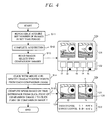
- FIG. 4 shows the manner in which measurement control and output display are performed in the present embodiment, and uses the same format as FIG. 2.
- the flowchart portion on the left side of FIG. 4 is the same as in FIG. 2, and the format of the output display on the right side of FIG. 4 is the same as in FIG. 2.
- the target substance is administered to the subject's eye by administering the subject's eye with an eye drop or ointment that includes the target substance, and after the target substance is administered to the subject's eye, measurement is performed according to the control sequence shown in FIG. 4.
- the user After the target substance is administered to the subject's eye, and blinking is confirmed in the subject's eye, the user performs a prescribed operation (using a keyboard or other device not shown in the drawing) to initiate imaging. A prescribed number of images are then captured within the prescribed imaging period in steps S11 and S12. The imaging interval and number of images captured are the same as in the previously described embodiment.
- step S13 the comparison images (t2 and t5) are displayed in the main display area 121 when two comparison images (t2 and t5) are selected using the thumbnail display area 122 of the screen 12a of the monitor 12 in the same manner as in the previously described embodiment.
- the user selects the two images that show target substances 124 and 125 which are considered to be the same.
- step S15 When the images of the target substances 124 and 125 are specified by being clicked on with the pointing device (mouse or the like) as indicated by the reference symbol C in step S14, the computation routine of step S15 is executed, and the lachrymal fluid movement speed is computed based on the distance between the target substances 124 and 125 considered to be the same in the two comparison images t2 and t5, and on the elapsed time found from the imaging time data of the comparison images t2 and t5.
- the lachrymal fluid movement speed can be computed, and the results can be displayed as shown in the lower right of FIG. 4.
- the target substance is administered to the lachrymal fluid of the subject's eye, the illuminating light of the white light source 1 is radiated, an image of the lachrymal fluid meniscus of the subject's eye is captured two or more times at different times by the CCD camera 7, the lachrymal fluid movement speed found from the images thus obtained can be displayed, and based on these results, the user can evaluate the severity of dry eye.
- the target substance is administered to the lachrymal fluid of the subject's eye and is imaged according to the present embodiment, the movement of the lachrymal fluid can be monitored even when an interference color does not occur, the movement speed of lachrymal fluid can be quantified regardless of the state of the subject's eye, and it is possible to overcome the drawback of the conventional configuration in which it was difficult to distinguish between a normal eye and a severely dry eye.
- the ophthalmic measuring apparatus of the present invention includes many components in its hardware that are shared by common configurations of ophthalmic imaging devices, and can therefore be implemented easily and at low cost using an existing ophthalmic imaging device.
- the ophthalmic measuring method of the present invention can also be easily and inexpensively implemented in the same manner in existing ophthalmic imaging hardware, or in partially modified hardware.
Landscapes
- Health & Medical Sciences (AREA)
- Life Sciences & Earth Sciences (AREA)
- Engineering & Computer Science (AREA)
- Medical Informatics (AREA)
- General Health & Medical Sciences (AREA)
- Physics & Mathematics (AREA)
- Surgery (AREA)
- Heart & Thoracic Surgery (AREA)
- Biomedical Technology (AREA)
- Molecular Biology (AREA)
- Animal Behavior & Ethology (AREA)
- Biophysics (AREA)
- Public Health (AREA)
- Veterinary Medicine (AREA)
- Ophthalmology & Optometry (AREA)
- Nuclear Medicine, Radiotherapy & Molecular Imaging (AREA)
- Radiology & Medical Imaging (AREA)
- Quality & Reliability (AREA)
- Computer Vision & Pattern Recognition (AREA)
- General Physics & Mathematics (AREA)
- Theoretical Computer Science (AREA)
- Pathology (AREA)
- Eye Examination Apparatus (AREA)
Abstract
Description
- The present invention relates to an ophthalmic measuring method and apparatus that can be used to screen dry eye and evaluate dry eye severity in a subject's eye.
- The recent increase in the number of patients with dry eye is considered to be caused by an increased number of workers at VDTs (Visual Display Terminal), contact lens wearers or the dryness of air-conditioned rooms. Disorders in the corneal epithelium, conjunctival epithelium, and various other ophthalmic disorders can occur in conjunction with dry eye, and the diagnosis of dry eye has become an important subject of ophthalmic field.
- Configurations have been proposed in the past for an ophthalmic apparatus for capturing an image of the lachrymal fluid layer of a subject's eye and observing, analyzing, and measuring the image in order to quantitatively evaluate conditions of dry eye.
- Embodiments of known techniques include a technique (see
Japanese Laid-open Patent Application Publication No. 1997-201334 Japanese Laid-open Patent Application Publication No. 1999-267102 - In the conventional techniques, particularly the technique described in
Japanese Laid-open Patent Application Publication No. 1997-201334 - In view of the foregoing drawbacks, an object of the present invention is to ensure that the movement speed of lachrymal fluid can be reliably measured, diagnosis can be quantitatively performed from the movement speed of the lachrymal fluid thus measured even on a severely dry eye, and the state of a normal eye can be reliably identified.
- The present invention provides an ophthalmic measuring method comprising the steps of administering a target substance to the lachrymal fluid of a subject's eye; irradiating the lachrymal fluid with illuminating light; electronically capturing a plurality of images of the illuminated lachrymal fluid of the subject's eye, the images being captured respectively at different times; measuring the movement speed of the target substance based on the positions thereof in the images selected among the plurality of captured images and the capturing times of the selected images; and outputting the measured movement speed of the target substance as the movement speed of the lachrymal fluid of the subject's eye.
- The present invention also provides an ophthalmic measuring apparatus comprising means for electronically capturing an image of the lachrymal fluid layer in a prescribed position of a subject's eye to which a target substance is administered; means for selecting images among a plurality of images captured; means for computing the movement speed of the target substance based on the positions thereof in the selected images and the capturing times of the selected images; and means for outputting the computed movement speed of the target substance as the movement speed of the lachrymal fluid of the subject's eye.
- According to the present invention, an image of the lachrymal fluid layer in a specific position of the subject's eye to which a target substance is administered is electronically captured a plurality of times, the image signal captured each time is computed and comparatively analyzed, and the movement speed of the target substance is measured as the movement speed of the lachrymal fluid of the subject's eye. The severity of dry eye is thus quantitatively evaluated based on the results of measuring the movement speed of the lachrymal fluid of the subject's eye.
- In the present invention, a target substance is administered to the subject's eye and its movement in the lachrymal fluid can be monitored even when an interference color does not occur. Therefore, the movement speed of lachrymal fluid can be quantified regardless of the state of the subject's eye, and there is no occurrence of the drawback of the prior art in which it was difficult to distinguish between a normal eye and a severely dry eye.
- Further features of the invention, its nature and various advantages will be more apparent from the accompanying drawings and following detailed description of the invention.
- FIG. 1 is a block diagram showing one embodiment of an ophthalmic measuring apparatus according to the present invention;
- FIG. 2 is a diagram showing the operation in the configuration shown in FIG. 1;
- FIG. 3 is a block diagram showing another embodiment of an ophthalmic measuring apparatus according to the present invention; and
- FIG. 4 is a diagram showing the operation in the configuration shown in FIG. 3.
- Embodiments of the present invention will be described hereinafter with reference to the drawings.
- FIG. 1 shows the simplified structure of an ophthalmic measuring apparatus according to the present invention. In this drawing, the
reference numeral 1 indicates a white light source composed of a halogen lamp or the like for illuminating a subject's eye E. Light radiated from thewhite light source 1 passes through amask 2 for limiting the field of illumination, and then illuminates a prescribed point P on the subject's eye E via alens 3, anexciter filter 3a, ahalf mirror 4, and alens 5. The position selected for this prescribed point P is the lipid layer of the outermost lachrymal fluid layer on the cornea of the subject's eye E. The intensity of thewhite light source 1 can be adjusted by a dimmer circuit (not shown in the drawing). - The light reflected from point P enters a
color CCD camera 7 via thelens 5, thehalf mirror 4, and alens 6, and the RGB (color) video signal thus captured is inputted to animage processing device 20. - The
image processing device 20 can be configured so as to utilize a personal computer (PC) or other hardware. Thisimage processing device 20 has avideo storage device 8 that is composed of a video capture interface and an HDD or other external storage device and is capable of real-time image output and the like to amonitor 12; animage processor 9 composed of a CPU and memory (ROM and RAM) or other computing resources; anoutput display controller 11 that uses themonitor 12 and controls the output display described hereinafter; and atimer 13 used for controlling the image acquisition timing of thevideo storage device 8, the timing of image output to themonitor 12, and other timings. - The
image processing device 20 also has a keyboard, a pointing device (mouse or the like), or another common operating device not shown in the drawings. Themonitor 12 is used as described hereinafter for output displays relating to ophthalmic measurement, and the abovementioned operating device andmonitor 12 constitute a user interface for ophthalmic measurement. - The operation according to the configuration described above will next be described.
- In the present embodiment, a target substance (tracer, marker, or other particulate substance, colorant, or the like that is not harmful to the test subject/subject's eye) is directly or indirectly administered to the lachrymal fluid of the subject's eye, the illuminating light of the
white light source 1 is radiated, an image of the lachrymal fluid of the subject's eye is electronically captured two or more times at different times by theCCD camera 7, each image signal thus captured is computed and comparatively analyzed, and the movement speed of the target substance is measured as the movement speed of the lachrymal fluid of the subject's eye. The severity of dry eye can be quantitatively evaluated based on these results of measuring the movement speed of the lachrymal fluid of the subject's eye. - The target substance is administered to the subject's eye by administering the subject's eye with an eye drop or ointment that includes the target substance, or by using another method. When a fluorescent target substance is used, the
exciter filter 3a is inserted in the optical path, and a barrier filter (not shown) is inserted in the optical path along theCCD camera 7. - After the target substance is administered to the subject's eye, measurement is performed according to the control sequence shown in FIG. 2. FIG. 2 shows the control sequence in the configuration of FIG. 1, and the state of the output display on the
monitor 12. The control sequence of FIG. 2 is stored in advance in the ROM (or HDD or the like) storage device of theimage processor 9 shown in FIG. 1. - After the target substance is administered to the subject's eye, and blinking is confirmed in the subject's eye, the user performs a prescribed operation (using a keyboard or other device not shown in the drawing) to initiate imaging. In step S11 of FIG. 2, the illuminating light of the
white light source 1 is directed to the subject's eye, and an image of the illuminated location is received by thevideo storage device 8 of theCCD camera 7. - An imaging period of about six seconds, for embodiment, is set at this time, and about 10 to 100 images are automatically and continuously captured. When 100 images are captured in six seconds, the image capture interval is 0.06 seconds. The appropriate imaging period is considered to be at least several seconds, since it is preferred that the target movement speed be able to be measured after blinking of the subject's eye following administration of the target substance. The
timer 13 is used to control the capture timing described above, and the capture time data of each image are stored in thevideo storage device 8 after being correlated with the captured images. - After image acquisition is completed in step S12, in step S13, the
image processor 9 controls themonitor 12 via theoutput display controller 11 and creates an output display such as the one shown in the upper right of FIG. 2. In this arrangement, thescreen 12a of themonitor 12 is divided into top and bottom portions, the top portion is themain display area 121, the bottom portion is thethumbnail display area 122, and a plurality of size-reduced thumbnail images of the captured images are displayed in thethumbnail display area 122. - In the
thumbnail display area 122,cursors cursors thumbnail display area 122 using a keyboard or pointing device (mouse or the like) not shown in the drawing and performing a prescribed selection operation. - In the embodiment depicted in the drawing, a state is shown in which images t2 and t5 are selected among five thumbnail images t1 through t5, and images t2 and t5 (comparison images) corresponding to these thumbnail images t2 and t5 are displayed in the
main display area 121. -
Target substances main display area 121. It is apparent that since the same target substance must be used to measure the movement speed of the lachrymal fluid, the user is required to select two images that showtarget substances - When the user can determine that
target substances target substances - Thus, in step S15, the lachrymal fluid movement speed is computed based on the distance between the
target substances CCD camera 7 so that the actual distance is obtained from the distance in the image. - According to the operation described above, the movement speed of lachrymal fluid can be computed, and the results thereof can be displayed as shown in the lower right of FIG. 2. The bottom portion of the
screen 12a in this arrangement is changed to ameasurement results area 123, and the lachrymal fluid movement speed in the transverse direction and lachrymal fluid movement speed in the longitudinal direction are numerically displayed in themeasurement results area 123. - According to the present embodiment as described above, the target substance is administered to the lachrymal fluid of the subject's eye, the illuminating light of the
white light source 1 is radiated, an image of the lachrymal fluid of the subject's eye is electronically captured two or more times at different times by theCCD camera 7, the lachrymal fluid movement speed found from the images thus obtained can be displayed, and based on these results, the user can evaluate the severity of dry eye. - Since the target substance is administered to the lachrymal fluid of the subject's eye and imaged according to the present embodiment, the movement of the lachrymal fluid can be monitored even when an interference color does not occur, the movement speed of lachrymal fluid can be quantified regardless of the state of the subject's eye, and it is possible to overcome the drawback of the conventional configuration in which it was difficult to distinguish between a normal eye and a severely dry eye.
- In the embodiment above the target substance was administered to the lachrymal fluid of the subject's eye, and the surface of the lachrymal fluid on the cornea of the subject's eye was imaged, but it is also possible to adopt a configuration in which the layer of lachrymal fluid accumulated in the lachrymal fluid meniscus along the lower eyelid of the subject's eye is imaged, as in the following embodiment.
- FIG. 3 depicts the manner in which measurement is performed in this embodiment. The hardware of the measuring apparatus in FIG. 3 is the same as in FIG. 1, but the illumination and optical axis of imaging by the measuring apparatus are aligned so that imaging is performed in the location of the lachrymal fluid layer (lachrymal fluid meniscus) accumulated in the lachrymal fluid meniscus along the lower eyelid of the subject's eye. The lachrymal fluid moves along the edge of the lower eyelid when the subject's eye blinks.
- In this type of configuration as well, the target substance is administered to the lachrymal fluid of the subject's eye, and the severity of dry eye can be evaluated from the movement speed of the target substance that is moving in the lachrymal fluid meniscus on the edge of the lower eyelid of the subject's eye.
- The overall sequence of the measurement operation in the present embodiment is substantially the same as in the previously described embodiment, except that the illumination and optical axis of imaging by the measuring apparatus are aligned in the vicinity of the lachrymal fluid meniscus along the lower eyelid of the subject's eye.
- FIG. 4 shows the manner in which measurement control and output display are performed in the present embodiment, and uses the same format as FIG. 2. The flowchart portion on the left side of FIG. 4 is the same as in FIG. 2, and the format of the output display on the right side of FIG. 4 is the same as in FIG. 2.
- In the same manner as in the previously described embodiment, the target substance is administered to the subject's eye by administering the subject's eye with an eye drop or ointment that includes the target substance, and after the target substance is administered to the subject's eye, measurement is performed according to the control sequence shown in FIG. 4.
- After the target substance is administered to the subject's eye, and blinking is confirmed in the subject's eye, the user performs a prescribed operation (using a keyboard or other device not shown in the drawing) to initiate imaging. A prescribed number of images are then captured within the prescribed imaging period in steps S11 and S12. The imaging interval and number of images captured are the same as in the previously described embodiment.
- In step S13, the comparison images (t2 and t5) are displayed in the
main display area 121 when two comparison images (t2 and t5) are selected using thethumbnail display area 122 of thescreen 12a of themonitor 12 in the same manner as in the previously described embodiment. - At this time, the user selects the two images that show
target substances - When the images of the
target substances target substances - According to the operation described above, the lachrymal fluid movement speed can be computed, and the results can be displayed as shown in the lower right of FIG. 4.
- According to the present embodiment as described above, the target substance is administered to the lachrymal fluid of the subject's eye, the illuminating light of the
white light source 1 is radiated, an image of the lachrymal fluid meniscus of the subject's eye is captured two or more times at different times by theCCD camera 7, the lachrymal fluid movement speed found from the images thus obtained can be displayed, and based on these results, the user can evaluate the severity of dry eye. - Since the target substance is administered to the lachrymal fluid of the subject's eye and is imaged according to the present embodiment, the movement of the lachrymal fluid can be monitored even when an interference color does not occur, the movement speed of lachrymal fluid can be quantified regardless of the state of the subject's eye, and it is possible to overcome the drawback of the conventional configuration in which it was difficult to distinguish between a normal eye and a severely dry eye.
- The ophthalmic measuring apparatus of the present invention includes many components in its hardware that are shared by common configurations of ophthalmic imaging devices, and can therefore be implemented easily and at low cost using an existing ophthalmic imaging device. The ophthalmic measuring method of the present invention can also be easily and inexpensively implemented in the same manner in existing ophthalmic imaging hardware, or in partially modified hardware.
Claims (5)
- An ophthalmic measuring method comprising the steps of:administering a target substance (124, 125) to the lachrymal fluid of a subject's eye (E);irradiating the lachrymal fluid with illuminating light(1);electronically capturing a plurality of images (t1 to t5) of the illuminated lachrymal fluid of the subject's eye, the images being captured respectively at different times;measuring the movement speed of the target substance (124, 125) based on the positions thereof in the images (t2, t5) selected among the plurality of captured images and the capturing times of the selected images; andoutputting the measured movement speed of the target substance (124, 125) as the movement speed of the lachrymal fluid of the subject's eye.
- An ophthalmic measuring method according to claim 1, in which the target substance (124, 125) is included in an eye drop or ointment that is administered to the subject's eye (E).
- An ophthalmic measuring method according to claim 1, wherein the images are captured at the lachrymal fluid layer on the corneal surface of the subject's eye to which the target substance (124, 125) has been administered, or at the position of the lachrymal fluid layer accumulated in the lachrymal fluid meniscus of the subject's eye (E).
- An ophthalmic measuring apparatus comprising:means (7) for electronically capturing an image of the lachrymal fluid layer in a prescribed position of a subject's eye (E) to which a target substance (124, 125) is administered;means (122a, 122b) for selecting images (t2, t5) among a plurality of images (t1 to t5) captured;means (20) for computing the movement speed of the target substance (124, 125) based on the positions thereof in the selected images (t2, t5) and the capturing times of the selected images; andmeans (12) for outputting the computed movement speed of the target substance (124, 125) as the movement speed of the lachrymal fluid of the subject's eye (E).
- An ophthalmic measuring apparatus according to claim 4, wherein the images are captured at the lachrymal fluid layer on the corneal surface of the subject's eye (E) to which the target substance (124, 125) has been administered, or at the position of the lachrymal fluid layer accumulated in the lachrymal fluid meniscus of the subject's eye.
Applications Claiming Priority (1)
| Application Number | Priority Date | Filing Date | Title |
|---|---|---|---|
| JP2005142035A JP4766919B2 (en) | 2005-05-16 | 2005-05-16 | Ophthalmic measuring method and ophthalmic measuring apparatus |
Publications (2)
| Publication Number | Publication Date |
|---|---|
| EP1723900A1 true EP1723900A1 (en) | 2006-11-22 |
| EP1723900B1 EP1723900B1 (en) | 2009-07-29 |
Family
ID=36658926
Family Applications (1)
| Application Number | Title | Priority Date | Filing Date |
|---|---|---|---|
| EP20060009876 Not-in-force EP1723900B1 (en) | 2005-05-16 | 2006-05-12 | Method and system to measure the lachrymal fluid |
Country Status (5)
| Country | Link |
|---|---|
| US (1) | US8996097B2 (en) |
| EP (1) | EP1723900B1 (en) |
| JP (1) | JP4766919B2 (en) |
| DE (1) | DE602006008063D1 (en) |
| ES (1) | ES2329396T3 (en) |
Cited By (3)
| Publication number | Priority date | Publication date | Assignee | Title |
|---|---|---|---|---|
| EP2564764A3 (en) * | 2011-08-30 | 2013-06-12 | Oculus Optikgeräte GmbH | Ophthalmological analysis apparatus and method |
| EP2529661A4 (en) * | 2010-01-29 | 2017-07-19 | Kowa Company, Ltd. | Ophthalmology device and image categorizing method |
| EP3666167A4 (en) * | 2017-08-07 | 2021-04-28 | Kowa Company, Ltd. | METHOD, COMPUTER PROGRAM AND DEVICE FOR EVALUATING THE TEAR CONDITION |
Families Citing this family (5)
| Publication number | Priority date | Publication date | Assignee | Title |
|---|---|---|---|---|
| DE102011081825B4 (en) | 2011-08-30 | 2013-10-10 | Oculus Optikgeräte GmbH | Ophthalmological analyzer and method |
| US10238534B2 (en) * | 2013-03-07 | 2019-03-26 | Novartis Ag | Systems and processes for eye moisturizing during ocular surgery |
| KR102393228B1 (en) * | 2015-05-11 | 2022-04-29 | 매직 립, 인코포레이티드 | Devices, methods and systems for biometric user recognition utilizing neural networks |
| JP2017136212A (en) * | 2016-02-03 | 2017-08-10 | 株式会社ニデック | Ophthalmologic apparatus |
| JP7725318B2 (en) * | 2020-09-30 | 2025-08-19 | 参天製薬株式会社 | Medical support device, medical support system, and program |
Citations (5)
| Publication number | Priority date | Publication date | Assignee | Title |
|---|---|---|---|---|
| DE3108878A1 (en) * | 1981-03-09 | 1982-09-16 | Franz-Josef Prof. Dr. Haberich | Method for examining the weting condition and/or the weting characteristic of a convex surface, and device for carrying out the method |
| JPH09201334A (en) | 1996-01-30 | 1997-08-05 | Kowa Co | Ophthalmic equipment |
| EP0943288A1 (en) * | 1998-03-20 | 1999-09-22 | Kowa Company Ltd. | Ophthalmic apparatus |
| EP1029504A1 (en) | 1999-02-18 | 2000-08-23 | Nidek Co., Ltd. | Ophthalmic apparatus |
| US20020180929A1 (en) * | 2001-04-25 | 2002-12-05 | Tseng Scheffer C.G. | Apparatus and method for the kinetic analysis of tear stability |
Family Cites Families (3)
| Publication number | Priority date | Publication date | Assignee | Title |
|---|---|---|---|---|
| US4747683A (en) * | 1986-01-17 | 1988-05-31 | Eye Research Institute Of Retina Foundation | Method and device for in vivo wetting determinations |
| US6236459B1 (en) * | 1998-11-05 | 2001-05-22 | University Of Miami | Thin film measuring device and method |
| JP4593573B2 (en) * | 2004-01-08 | 2010-12-08 | オスモペン, リミテッド ライアビリティ カンパニー | Surface plasmon resonance type nanoliter osmometer |
-
2005
- 2005-05-16 JP JP2005142035A patent/JP4766919B2/en not_active Expired - Fee Related
-
2006
- 2006-05-12 EP EP20060009876 patent/EP1723900B1/en not_active Not-in-force
- 2006-05-12 ES ES06009876T patent/ES2329396T3/en active Active
- 2006-05-12 DE DE200660008063 patent/DE602006008063D1/en active Active
- 2006-05-15 US US11/434,657 patent/US8996097B2/en not_active Expired - Fee Related
Patent Citations (5)
| Publication number | Priority date | Publication date | Assignee | Title |
|---|---|---|---|---|
| DE3108878A1 (en) * | 1981-03-09 | 1982-09-16 | Franz-Josef Prof. Dr. Haberich | Method for examining the weting condition and/or the weting characteristic of a convex surface, and device for carrying out the method |
| JPH09201334A (en) | 1996-01-30 | 1997-08-05 | Kowa Co | Ophthalmic equipment |
| EP0943288A1 (en) * | 1998-03-20 | 1999-09-22 | Kowa Company Ltd. | Ophthalmic apparatus |
| EP1029504A1 (en) | 1999-02-18 | 2000-08-23 | Nidek Co., Ltd. | Ophthalmic apparatus |
| US20020180929A1 (en) * | 2001-04-25 | 2002-12-05 | Tseng Scheffer C.G. | Apparatus and method for the kinetic analysis of tear stability |
Non-Patent Citations (2)
| Title |
|---|
| EIKI GOTO AND SCHEFFER C.G.TSENG: "Kinetic Analysis of Tear Interference Images in Aqueous Tear Deficiency Dry Eye before and after Punctal Occlusion", INVESTIGATIVE & VISUAL SCIENCE, vol. 44, no. 5, 1 May 2003 (2003-05-01), pages 1897 - 1905, XP002391239 * |
| PATENT ABSTRACTS OF JAPAN vol. 1997, no. 12 25 December 1997 (1997-12-25) * |
Cited By (5)
| Publication number | Priority date | Publication date | Assignee | Title |
|---|---|---|---|---|
| EP2529661A4 (en) * | 2010-01-29 | 2017-07-19 | Kowa Company, Ltd. | Ophthalmology device and image categorizing method |
| EP2564764A3 (en) * | 2011-08-30 | 2013-06-12 | Oculus Optikgeräte GmbH | Ophthalmological analysis apparatus and method |
| US8899753B2 (en) | 2011-08-30 | 2014-12-02 | Oculus Optikgeraete Gmbh | Ophthalmological analysis instrument and method |
| EP3666167A4 (en) * | 2017-08-07 | 2021-04-28 | Kowa Company, Ltd. | METHOD, COMPUTER PROGRAM AND DEVICE FOR EVALUATING THE TEAR CONDITION |
| US11514570B2 (en) | 2017-08-07 | 2022-11-29 | Kowa Company, Ltd. | Tear fluid state evaluation method, computer program, and device |
Also Published As
| Publication number | Publication date |
|---|---|
| US20060263297A1 (en) | 2006-11-23 |
| JP4766919B2 (en) | 2011-09-07 |
| EP1723900B1 (en) | 2009-07-29 |
| ES2329396T3 (en) | 2009-11-25 |
| JP2006314651A (en) | 2006-11-24 |
| US8996097B2 (en) | 2015-03-31 |
| DE602006008063D1 (en) | 2009-09-10 |
Similar Documents
| Publication | Publication Date | Title |
|---|---|---|
| CN101730500B (en) | Apparatus and method for objective perimetry visual field test | |
| JP5704879B2 (en) | Fundus observation device | |
| EP3669754B1 (en) | Assessment of fundus images | |
| JP4783018B2 (en) | Method and apparatus for detecting and tracking the eye and its gaze direction | |
| RU2455686C2 (en) | Apparatus and method for identifying facial areas | |
| US9028065B2 (en) | Ophthalmologic apparatus and image classification method | |
| JP4113005B2 (en) | Eye examination equipment | |
| US7810928B2 (en) | Evaluating pupillary responses to light stimuli | |
| US6616277B1 (en) | Sequential eye screening method and apparatus | |
| JP5850292B2 (en) | Ophthalmic equipment | |
| EP3769283B1 (en) | Pupil edge detection in digital imaging | |
| EP1974657B1 (en) | Cornea imaging apparatus and cornea imaging method | |
| US8996097B2 (en) | Ophthalmic measuring method and apparatus | |
| US7866820B2 (en) | Corneo-scleral topography system | |
| JP5038925B2 (en) | Ophthalmic measuring device | |
| WO2008062527A1 (en) | Fundus photographing device | |
| JP2005102948A (en) | Perimeter | |
| US11998274B2 (en) | Ophthalmic photographing apparatus | |
| JP2002000567A (en) | Method of measuring pupil center position and method of detecting view point position | |
| CN103799964B (en) | Ophthalmoligic instrument and ophthalmic image taking method | |
| CN116138729B (en) | Parameter determining method and system based on fundus camera and intelligent terminal | |
| EP4133992A1 (en) | Determining color vision ability using a vision screening device | |
| JP4104302B2 (en) | Anterior segment analysis device and anterior segment analysis program | |
| US20220338730A1 (en) | Device and method for detecting tear film breakup | |
| JPH04279143A (en) | Eyeball motion inspector |
Legal Events
| Date | Code | Title | Description |
|---|---|---|---|
| PUAI | Public reference made under article 153(3) epc to a published international application that has entered the european phase |
Free format text: ORIGINAL CODE: 0009012 |
|
| AK | Designated contracting states |
Kind code of ref document: A1 Designated state(s): AT BE BG CH CY CZ DE DK EE ES FI FR GB GR HU IE IS IT LI LT LU LV MC NL PL PT RO SE SI SK TR |
|
| AX | Request for extension of the european patent |
Extension state: AL BA HR MK YU |
|
| 17P | Request for examination filed |
Effective date: 20061124 |
|
| 17Q | First examination report despatched |
Effective date: 20070118 |
|
| AKX | Designation fees paid |
Designated state(s): DE ES FR GB IT |
|
| GRAP | Despatch of communication of intention to grant a patent |
Free format text: ORIGINAL CODE: EPIDOSNIGR1 |
|
| RTI1 | Title (correction) |
Free format text: METHOD AND SYSTEM TO MEASURE THE LACHRYMAL FLUID |
|
| GRAS | Grant fee paid |
Free format text: ORIGINAL CODE: EPIDOSNIGR3 |
|
| GRAA | (expected) grant |
Free format text: ORIGINAL CODE: 0009210 |
|
| AK | Designated contracting states |
Kind code of ref document: B1 Designated state(s): DE ES FR GB IT |
|
| REG | Reference to a national code |
Ref country code: GB Ref legal event code: FG4D |
|
| REF | Corresponds to: |
Ref document number: 602006008063 Country of ref document: DE Date of ref document: 20090910 Kind code of ref document: P |
|
| REG | Reference to a national code |
Ref country code: ES Ref legal event code: FG2A Ref document number: 2329396 Country of ref document: ES Kind code of ref document: T3 |
|
| PLBE | No opposition filed within time limit |
Free format text: ORIGINAL CODE: 0009261 |
|
| STAA | Information on the status of an ep patent application or granted ep patent |
Free format text: STATUS: NO OPPOSITION FILED WITHIN TIME LIMIT |
|
| 26N | No opposition filed |
Effective date: 20100503 |
|
| REG | Reference to a national code |
Ref country code: FR Ref legal event code: PLFP Year of fee payment: 11 |
|
| REG | Reference to a national code |
Ref country code: FR Ref legal event code: PLFP Year of fee payment: 12 |
|
| REG | Reference to a national code |
Ref country code: FR Ref legal event code: PLFP Year of fee payment: 13 |
|
| PGFP | Annual fee paid to national office [announced via postgrant information from national office to epo] |
Ref country code: GB Payment date: 20180329 Year of fee payment: 13 |
|
| PGFP | Annual fee paid to national office [announced via postgrant information from national office to epo] |
Ref country code: ES Payment date: 20180605 Year of fee payment: 13 Ref country code: DE Payment date: 20180502 Year of fee payment: 13 |
|
| PGFP | Annual fee paid to national office [announced via postgrant information from national office to epo] |
Ref country code: FR Payment date: 20180412 Year of fee payment: 13 Ref country code: IT Payment date: 20180522 Year of fee payment: 13 |
|
| REG | Reference to a national code |
Ref country code: DE Ref legal event code: R119 Ref document number: 602006008063 Country of ref document: DE |
|
| GBPC | Gb: european patent ceased through non-payment of renewal fee |
Effective date: 20190512 |
|
| PG25 | Lapsed in a contracting state [announced via postgrant information from national office to epo] |
Ref country code: DE Free format text: LAPSE BECAUSE OF NON-PAYMENT OF DUE FEES Effective date: 20191203 Ref country code: IT Free format text: LAPSE BECAUSE OF NON-PAYMENT OF DUE FEES Effective date: 20190512 Ref country code: GB Free format text: LAPSE BECAUSE OF NON-PAYMENT OF DUE FEES Effective date: 20190512 |
|
| PG25 | Lapsed in a contracting state [announced via postgrant information from national office to epo] |
Ref country code: FR Free format text: LAPSE BECAUSE OF NON-PAYMENT OF DUE FEES Effective date: 20190531 |
|
| REG | Reference to a national code |
Ref country code: ES Ref legal event code: FD2A Effective date: 20200930 |
|
| PG25 | Lapsed in a contracting state [announced via postgrant information from national office to epo] |
Ref country code: ES Free format text: LAPSE BECAUSE OF NON-PAYMENT OF DUE FEES Effective date: 20190513 |