EP1723749B1 - Verfahren und system zum übermitteln von daten zu einem drahtlosen zugangspunkt - Google Patents
Verfahren und system zum übermitteln von daten zu einem drahtlosen zugangspunkt Download PDFInfo
- Publication number
- EP1723749B1 EP1723749B1 EP05725077.1A EP05725077A EP1723749B1 EP 1723749 B1 EP1723749 B1 EP 1723749B1 EP 05725077 A EP05725077 A EP 05725077A EP 1723749 B1 EP1723749 B1 EP 1723749B1
- Authority
- EP
- European Patent Office
- Prior art keywords
- access point
- transceiver
- rfid
- wireless
- mobile unit
- Prior art date
- Legal status (The legal status is an assumption and is not a legal conclusion. Google has not performed a legal analysis and makes no representation as to the accuracy of the status listed.)
- Expired - Lifetime
Links
Images


Classifications
-
- H—ELECTRICITY
- H04—ELECTRIC COMMUNICATION TECHNIQUE
- H04W—WIRELESS COMMUNICATION NETWORKS
- H04W48/00—Access restriction; Network selection; Access point selection
- H04W48/18—Selecting a network or a communication service
-
- H—ELECTRICITY
- H04—ELECTRIC COMMUNICATION TECHNIQUE
- H04W—WIRELESS COMMUNICATION NETWORKS
- H04W88/00—Devices specially adapted for wireless communication networks, e.g. terminals, base stations or access point devices
- H04W88/08—Access point devices
- H04W88/10—Access point devices adapted for operation in multiple networks, e.g. multi-mode access points
Definitions
- This invention relates to the field of wireless communication, and more specifically to an access point for facilitating communication with one or more devices in a wireless local area network, a system for communicating data through the network, and a mobile unit for use in a wireless communication network.
- Wireless methods of communication are becoming increasingly important in many different fields of endeavor. For example, computer users who were once shackled to modems or wired network connections are now able to roam freely as they access networks wirelessly.
- the demand for wireless access has led to the development of wireless access points.
- Wireless access points are devices that include one or more wireless transceivers that can communicate with mobile users. Data received from the mobile user can then be sent throughout a network via the access point's network connection, which may be an Ethernet connection to a local area network or a wireless connection to another access point.
- a network that includes wireless access points is known as a wireless local area network (WLAN).
- WLAN wireless local area network
- WLANs are being used in warehouses.
- different workers may use a host of wireless devices to check inventory and relay that information back to a server computer.
- one or more wireless access points may be provided.
- the wireless access points may be coupled to a computer or local area network such that data received by the access point from a wireless device may be transferred to a wired network.
- the wireless access points in a warehouse can also be used for inventory control purposes. This can be accomplished by integrating a radio frequency identification device (RFID) transceiver into the wireless access point.
- RFID radio frequency identification device
- the RFID transceiver can be used to interrogate RFID tags mounted on various items, such as a box, by broadcasting a radio frequency signal.
- the RFID tag then responds to the interrogation.
- the tag responds by back scattering the interrogation signal with a modulation that can carry data back to the RFID receiver.
- the information received from the tag may include the identity of the object the tag is attached to, information about the object the tag is attached to, the location of the object the tag is attached to, and the like.
- mobile units in a warehouse setting may also be outfitted with RFID transceivers. This allows the mobile unit to interrogate and receive responses from RFID tags as part of an overall RFID inventory control system.
- a drawback of this system is that at certain times an access point may be busy sending or receiving data for one or more users. When the access point is busy, other attempts to send data to the access point via the wireless LAN will be unsuccessful. This leads to inefficiencies in the system. What is needed is a method and system for communicating data to wireless access points.
- a system for communicating data through a network includes at least one access point and at least one mobile unit.
- the access point includes an access point processor, a wireless transceiver and a RFID transceiver.
- the wireless transceiver is coupled to the access point processor and the wireless transceiver is configured to receive and transmit data to a wireless device in the wireless local area network.
- the RFID transceiver is coupled to the access point processor and the RFID transceiver is configured to receive data from the at least one mobile unit in the wireless local area network when the wireless transceiver is unavailable.
- the mobile unit includes a mobile unit processor, a mobile unit wireless transceiver and a mobile unit RFID transceiver.
- the mobile unit wireless transceiver is coupled to the mobile unit processor and the mobile unit wireless transceiver is configured to receive and transmit data to the access point.
- the mobile RFID transceiver is coupled to the mobile unit processor and the mobile unit processor is configured to send data to the RFID transceiver of the access point when the wireless transceiver of the access point is unavailable.
- the wireless transceiver of the access point is unavailable when the wireless transceiver of the access point is busy.
- WO 02/096032 A2 describes a mobile communication network comprising at least one base transceiver station configured to communicate with mobile terminals connected to a corresponding coverage cell.
- WO 02/11074 A2 describes a changeable cover for an electronic device and method of using same in a payment system is provided.
- the wireless transceiver of the access point is unavailable when the wireless transceiver of the access point is inoperative.
- the wireless transceiver is unavailable because the data sent by the wireless device is predesignated for reception by the RFID transceiver to reduce demands on the wireless transceiver.
- FIGs. 1-3 A system 100, in accordance with one embodiment of the invention is illustrated in FIGs. 1-3 .
- the system 100 comprises one or more mobile units 102 and one or more access points 104 having one or more RFID antennas 106 coupled, in one embodiment, to access point 104 via a cable 105.
- multiple access points 104 may be distributed throughout an area, such as a warehouse.
- the access points 104 are coupled to a computer 110 via connection 108.
- Computer 110 may be a standard computer or a computer network or any other device capable of receiving and transmitting data with the access point 104.
- Connection 108 maybe a wired connection, such as an Ethernet connection or a wireless connection.
- Mobile unit 102 is any device capable of wirelessly communicating with one or more access points 104 using either a wireless LAN signal 109 or by using a RFID signal 107. Mobile unit 102 may also gather data as part of an RFID system.
- the wireless LAN signal 109 is compliant with IEEE standard 802.11 and the RFID signal is compliant with any one of a number of RFID standards as discussed in The RFID Handbook by Klaus Finkenzeller. Other protocols for both the LAN signal 109 and the RFID signal 107 can be used without departing from the scope of the present invention.
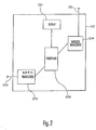
- mobile unit 102 in one embodiment of the in vention comprises a mobile unit RFID transceiver 202 coupled to one or more RFID antennas 208, a mobile unit wireless transceiver 204, a mobile unit processor 206 coupled to the mobile RFID transceiver 202, the mobile unit wireless transceiver 204 and a display 210.
- Mobile unit 102 may also include an input device, such as a keyboard, touch sensitive display, track ball or any other suitable input device.
- Mobile unit RFID transceiver 202 in conjunction with one or more mobile unit RFID antennas 208, may interrogate RFID tags and receive responses from the tags. This process is well known in the art. Additionally, mobile unit RFID transceiver 202 may send data to another device with an RFID transceiver, such as access point 104. For example, mobile unit RFID transceiver 202 may send a simulated back scatter signal to the wireless access point 104. This allows mobile unit 102 to send data via the mobile unit RFID transceiver 202 to access point 104 when the access point 104 cannot accept any wireless local area network communications.
- the inability of access point 104 to receive local area network communications may be because the access point 104 is busy with other wireless local area network communications, because the access point 104 is partially inoperative in that it cannot accept wireless local area network communications, or for some other reason.
- Several different manufacturers including Texas Instruments of Plano, Texas, manufacture suitable RFID transceivers and/or wireless RFID readers.
- Mobile unit wireless transceiver 204 in conjunction with mobile unit wireless antenna 212, wirelessly receives data from access points 104 and transmits data to access points 104, other mobile units or any other wireless device.
- mobile unit wireless transceiver 204 is compliant with IEEE standard 802.11a, 802.11b or 802.11g, although for the purpose of the present invention any wireless protocol can be used.
- Wireless transceivers are commercially available from a number of manufacturers, including RF Micro Devices of Greensboro, North Carolina.
- Mobile unit processor 206 may be any commonly available microprocessor such as processors manufactured by Hitachi, MICROCHIP, and AMD. Processor 206 runs processes necessary for the operation of the mobile unit 102. In one exemplary embodiment, mobile unit processor 206 executes routines that allow the mobile unit 102 to determine if the nearest access point 104 is busy. For example, mobile unit processor 206 may execute routines that cause the mobile unit 102 to issue a probe request to the nearest access point 104 to determine if the access point 104 is busy. Also, mobile unit processor 206 may execute routines that cause the mobile unit 102 to conduct a clear channel assessment to see if the access point 104 is busy. Clear channel assessments and probe requests are two of many well known methods to check if a system is busy. If these or any other indication shows that the nearest access point 104 is busy, mobile unit 102 can transfer data using the mobile unit RFID transceiver 202. This is discussed more fully in conjunction with the description for FIG. 4 and FIG. 5 .
- the display 210 provides visual feedback of the operation of the mobile unit 102.
- Display 210 can utilize any display technology, but preferably requires a readable, light weight display, such as LCD displays, LED displays, plasma displays and the like.
- display 210 is a touch sensitive display.
- mobile unit 102 is typically a device that can be moved from one location to another, whether hand held or otherwise movable, mobile unit 102 may also be a fixed, non moveable unit capable of communicating with access point 104 via either a wireless LAN transceiver or RFID transceiver.
- Access point 104 is any device that can receive data and transmit data wirelessly and connects users to other users in a network or to a network. Access point 104 may also serve as a connection point between the wireless LAN and a fixed wired network. For example, in FIG. 1 access point 104 is coupled to a computer network 110 via a connection 108. Typically, each access point 104 may serve multiple users in a defined area. Usually, the access point 104 is able to handle all wireless LAN communications in a given area. However, the access point 104 may become busy, such as when one of the user requests a large amount of information (e.g. streaming video or multiple streams of real-time voice over IP communications packets).
- a large amount of information e.g. streaming video or multiple streams of real-time voice over IP communications packets.
- multiple access points 104 can be used.
- the access points 104 may include protocols that allow the access point 104 to hand off mobile units 102 from one access point 104 to another as the mobile unit 102 moves about.
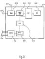
- Access point 104 as illustrated in FIG. 3 , comprises a DSP 302, coupled to a wireless LAN baseband chip 304, which is coupled to a WLAN transceiver 306 having one or more wireless LAN antennas 307.
- DSP 302 is also coupled to a power over Ethernet (POE) controller 308.
- POE controllers 308 are known in the art and are covered by IEEE standards 802.3a-f.
- the POE controller 308 couples to a computer or a computer network. While these components are typical components in wireless access points; different, additional or less components can be included in a wireless access point without departing from the scope of the present invention.
- the access point 104 may also include an RFID transceiver 310, coupled to an antenna switch 312, which couples to one or more RFID antennas 106.
- the RFID transceiver 310 also couples to the DSP 302 via glue logic 316.
- Glue logic 316 is any device or computer code that allows the RFID transceiver 310 to connect to and communicate with the wireless LAN portion of the access point 104. Via glue logic 316, data sent to the RFID transceiver 310 by a mobile unit 102 can be sent to and manipulated by the DSP 302.
- Wireless LAN transceiver 306 in conjunction with one or more wireless LAN antennas 307 is any device capable of communicating wirelessly with other wireless devices.
- Wireless LAN transceiver 306 may receive data from and transmit data to other wireless devices such as mobile unit 102.
- Wireless LAN transceiver may be compliant with wireless standards such as IEEE standards 802.11a, 802.11b and 802.11g, although the present invention can utilize any wireless protocol.
- wireless LAN transceivers are known in the art and commercially available.
- Wireless baseband chip 304 converts received wireless signals to a digital signal so DSP 302 can manipulate the data received by the wireless LAN transceiver 306. Also, the wireless baseband chip 304 converts digital signals generated by the DSP 302 to a signal that can be presented to the wireless LAN antenna 307.
- DSP 302 is any processor capable of receiving and manipulating data. For example, DSP 302 may convert the digitized data to packet format for transmission over a network. DSP 302 may also receive data from RFID transceiver 310 and convert that data to packet format. DSPs are commonly available from many manufacturers such as Texas Instruments of Plano, Texas.
- Power over Ethernet controller 308 is any device that can handle the transmission and reception of data packets over a wired network and provide power to the circuitry of the access point 104.
- Power over Ethernet controllers 308 are available from manufacturers such as NETGEAR of South Hackensack, New Jersey. Alternatively, power can be provided to the access point 104 via any conventional means such as batteries a direct connection to a power source, and the like.
- RFID transceiver 310 is any device that can broadcast interrogations to RFID tags and receive responses to the interrogations. RFID transceiver 310 may also help determine the location of an object with an associated a RFID tag.
- Antenna switch 312 is any device that is capable of switching RFID transceiver 310 between the one or more RFID antennas 106. By providing multiple RFID antennas 106, coverage of the RFID transceiver 310 can be increased. As shown in FIG. 3 , four different RFID antennas 106 are connected to access point 104. By switching between one of the four RFID antennas 106, different RFID antennas 106 can be used to send an interrogation to a RFID tag. If the same interrogation is conducted with three or more antennas, the RFID transceiver 310 can be used to locate RFID tags by well-known method such as triangulation.
- RFID antennas 106 are coupled to access point 104 via the cable 105, such as a coaxial cable. This allows for RFID antennas 106 to be placed remotely from the access point 104.
- the RFID antennas 106 can be placed outside the coverage area of the wireless LAN transceiver 306 to allow a mobile user to access a remote access point via the RFID transceiver 310 even if it can not access the access point via the wireless LAN transceiver 306. This increases the density of the RFID antennas in a given area.
- RFID antennas can be collocated with the access point 104.
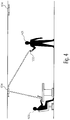
- FIG. 4 illustrates an exemplary use of the present invention.
- FIG. 4 illustrates mobile unit 102 operating inside a structure having at least one access point 104 mounted to the ceiling. However, other mounting can be utilized in accordance with the present invention.
- Each access point 104 in this example, has four RFID antennas coupled to it, although only two are visible in FIG. 4 .
- the access point 104 can be connected to a wired network via connection 108.
- Mobile unit 102 which is operated by first user 401, has data that it wants to communicate via access point 104 to the wired network 110. However, at the time the communication is ready for transferring from the mobile unit 102, the WLAN transceiver 306 of access point 104 is busy. For example, the WLAN transceiver 306 of access point 104 may already be wirelessly communicating with a second user 402. The second users 402 demands on the access point 104 are such that the access point 104 is unable to receive data from the mobile unit 102 at this time. As discussed previously, mobile unit 102 may determine that the access point 104 is busy by issuing a probe request, by performing a clear channel assessment or by performing some other test to see if access point 104 is busy.
- mobile unit 102 sends the information through the mobile unit RFID transceiver 202.
- the mobile unit RFID transceiver 202 of the mobile unit 102 will, in one embodiment of the present invention, send the data in a signal form that is similar to what an RFID tag would send in response to an interrogation.
- the mobile unit RFID transceiver 202 sends a transmission similar in form to a RFID tag response (e.g. a simulated backscattered signal) to the access point 104 via the RFID antenna 106 and RFID transceiver 310 of the access point 104.
- a RFID tag response e.g. a simulated backscattered signal
- simulated backscattered signals can be used, any format or protocol that is mutually compatible between the mobile unit RFID transceiver 202 and the RFID transceiver 310 of the access port can be used.
- the data can then be sent through the connection 108 of the access point 104 and to a computer network 110 or similar device.
- the access point 104 is able to handle more data then if just the mobile unit wireless transceiver 204 was used. Both the first user 401 and the second user 402 are able to communicate effectively.
- the WLAN transceiver 306 converts received modulated bits and assembles them into compressed packets before transferring them to the DSP 302.
- DSP 302 preferably has enough processing capability to take multiple data streams and send the data to the common wired network.
- the DSP 302 processing ability may also become a bottleneck in some situations, such as when the demands are very high from both the wired network side and the wireless transceiver side.
- a second access point that has a free processor can be used.
- FIG. 5 which is an overhead view of a mobile user 502 in a wireless LAN environment
- user 502 is within range of a first access point 504 but is outside the WLAN range of second access point 506. That is, the user 502 can communicate with first access point 504 via a WLAN connection but can not communicate with second access point 506 via a WLAN connection.
- second access point 506 has at least one second access point RFID antenna 508 that is in the range of the user's 502 ability to send an RFID transmission.
- User 502 is also within the range of at least one of first access point RFID antenna 510.
- the user 502 can send data to the second access point RFID antenna 508 of second access point 506. The data can then be processed by the second access point 506.
- the mobile unit 102 can communicate with the access point 104 via the RFID transceivers of each device when the WLAN transceiver 306 is busy (unavailable).
- unavailable in the context of the present invention is a broader concept and includes any situation when the WLAN transceiver is unavailable, such as failure of the WLAN transceiver 306 or lack of capacity for the DSP 302.
- unavailable also includes the situation where the mobile RFID transceiver 202 always communicates certain predetermined data to the RFID transceiver 310 of the access port 104.
- the RFID transceiver of the access point 104 can be configured to always receive certain transmissions such as slow data rate updates, configurations, status, device monitoring, device management, and the like. This frees up bandwidth of the WLAN transceiver.
- the WLAN transceiver of the access point can be free for other transmissions, increasing the overall capacity of the system 100.
Landscapes
- Engineering & Computer Science (AREA)
- Computer Security & Cryptography (AREA)
- Computer Networks & Wireless Communication (AREA)
- Signal Processing (AREA)
- Mobile Radio Communication Systems (AREA)
Claims (14)
- Zugangspunkt (104) zum Ermöglichen von Kommunikation mit einem oder mehreren Geräten in einem drahtlosen lokalen Netzwerk, wobei der Zugangspunkt Folgendes aufweist:einen Zugangspunktprozessor (302);einen drahtlosen Transceiver (306), aufweisend mindestens eine drahtlose Antenne (307), wobei der drahtlose Transceiver mit dem Zugangspunktprozessor verbunden ist, der drahtlose Transceiver konfiguriert ist zum Empfangen und Übertragen von Daten an mindestens eines des einen oder der mehreren drahtlosen Geräte im drahtlosen lokalen Netzwerk, wobei:das eine oder die mehreren drahtlosen Geräte im drahtlosen lokalen Netzwerk ferner angeordnet sind zum Senden der Daten als ein simuliertes rückgestreutes Signal von einem Mobileinheit-RFID-Transceiver (202) an eine RFID-Antenne (106) eines RFID-Transceivers (310) des Zugangspunkts; undder RFID-Transceiver (310) zwei oder mehrere RFID-Antennen (106) aufweist, der RFID-Transceiver mit dem Zugangspunktprozessor verbunden ist, der RFID-Transceiver konfiguriert ist zum Empfangen von Daten als das simulierte rückgestreute Signal von mindestens einem des einen oder der mehreren drahtlosen Geräte im drahtlosen lokalen Netzwerk, wenn der drahtlose Transceiver nicht verfügbar ist,wobei die zwei oder mehreren RFID-Antennen (106) mit dem RFID-Transceiver über einen Antennenschalter (312) verbunden sind, der konfiguriert ist zum Verbinden des RFID-Transceivers mit einer der zwei oder mehreren, entfernt vom Zugangspunkt (104) angeordneten und über Koaxialkabel (105) mit dem Zugangspunkt verbundenen RFID-Antennen.
- Zugangspunkt (104) nach Anspruch 1, wobei der Zugangspunkt über eine Ethernet-Verbindung versorgt wird.
- Zugangspunkt (104) nach Anspruch 1, wobei der Zugangspunkt mit einem drahtgebundenen lokalen Netzwerk verbunden ist.
- Zugangspunkt (104) nach Anspruch 1, wobei der drahtlose Transceiver (306) nicht verfügbar ist, weil der drahtlose Transceiver mit der Handhabung anderer Daten beschäftigt ist.
- Zugangspunkt (104) nach Anspruch 1, wobei der drahtlose Transceiver (306) nicht verfügbar ist, weil der drahtlose Transceiver nicht funktionsfähig ist.
- System (100) zum Übermitteln von Daten durch ein Netzwerk, aufweisend:einen Zugangspunkt (104), aufweisend:einen Zugangspunktprozessor (302);einen drahtlosen Transceiver (306), aufweisend mindestens eine drahtlose Antenne (307), wobei der drahtlose Transceiver mit dem Zugangspunktprozessor verbunden ist, der drahtlose Transceiver konfiguriert ist zum Empfangen und Übertragen von Daten an mindestens eines des einen oder der mehreren drahtlosen Geräte im drahtlosen lokalen Netzwerk, wobei:das eine oder die mehreren drahtlosen Geräte im drahtlosen lokalen Netzwerk ferner angeordnet sind zum Senden der Daten als ein simuliertes rückgestreutes Signal von einem Mobileinheit-RFID-Transceiver (202) an eine RFID-Antenne (106) eines RFID-Transceivers (310) des Zugangspunkts;der RFID-Transceiver (310) zwei oder mehrere RFID-Antennen (106) aufweist, der RFID-Transceiver mit dem Zugangspunktprozessor verbunden ist, der RFID-Transceiver konfiguriert ist zum Empfangen von Daten als das simulierte rückgestreute Signal von dem einem oder den mehreren drahtlosen Geräten im drahtlosen lokalen Netzwerk, wenn der drahtlose Transceiver nicht verfügbar ist;wobei die zwei oder mehreren RFID-Antennen (106) mit dem RFID-Transceiver über einen Antennenschalter (312) verbunden ist, der konfiguriert ist zum Verbinden des RFID-Transceivers mit einer der zwei oder mehreren, entfernt vom Zugangspunkt (104) angeordneten und über Koaxialkabel (105) mit dem Zugangspunkt verbundenen RFID-Antennen; und das System ferner aufweist:eine Mobileinheit (102), aufweisend:einen Mobileinheit-Prozessor (206);einen Mobileinheit-Drahtlostransceiver (204), aufweisend mindestens eine Mobileinheit-Transceiver-Antenne (212), wobei der Mobileinheit-Transceiver mit dem Mobileinheit-Prozessor verbunden ist, der Mobileinheit-Drahtlostransceiver konfiguriert ist zum Empfangen und Übertragen von Daten vom und zum Zugangspunkt (104);wobei der Mobileinheit-RFID-Transceiver (202) mindestens eine Mobileinheit-RFID-Transceiver-Antenne (208) aufweist, der Mobileinheit-RFID-Transceiver mit dem Mobileinheit-Prozessor verbunden ist, der Mobileinheit-Prozessor konfiguriert ist zum Senden der Daten als das simulierte rückgestreute Signal an den RFID-Transceiver des Zugangspunkts (104), wenn der drahtlose Transceiver des Zugangspunkts (104) nicht verfügbar ist.
- System (100) nach Anspruch 6, wobei der Zugangspunkt (104) über eine Ethernet-Verbindung versorgt wird.
- System (100) nach Anspruch 6, wobei der Zugangspunkt (104) mit einem drahtgebundenen lokalen Netzwerk verbunden ist.
- System (100) nach Anspruch 6, wobei der drahtlose Transceiver (306) nicht verfügbar ist, weil der drahtlose Transceiver mit der Handhabung anderer Daten beschäftigt ist.
- System (100) nach Anspruch 6, wobei der drahtlose Transceiver (306) nicht verfügbar ist, weil der drahtlose Transceiver nicht funktionsfähig ist.
- System (100) nach Anspruch 6, wobei der Zugangspunkt (104) konfiguriert ist zum Abfragen von RFID-Tags, die auf Gegenständen platziert sind.
- System (100) nach Anspruch 6, wobei die Mobileinheit (102) konfiguriert ist, um als RFID-Leser benutzt zu werden.
- System (100) nach Anspruch 6, wobei der Mobileinheit-Prozessor (206) einen Computercode ausführt, um eine Überprüfung einzuleiten, um zu bestimmen, ob der drahtlose Transceiver des Zugangspunkts (104) nicht verfügbar ist.
- System (100) nach Anspruch 6, ferner aufweisend einen zweiten Zugangspunkt (506), der einen zweiten RFID-Transceiver aufweist, der mit zwei oder mehreren RFID-Antennen (508) verbunden ist, und einen zweiten drahtlosen Transceiver, wobei der zweite drahtlose Transceiver außerhalb des Bereichs des drahlosen Mobileinheit-Transceivers ist und mindestens eine der zwei oder mehreren RFID-Antennen innerhalb des Bereichs der Mobileinheit-RFID-Antenne ist.
Applications Claiming Priority (2)
| Application Number | Priority Date | Filing Date | Title |
|---|---|---|---|
| US10/799,064 US7385476B2 (en) | 2004-03-11 | 2004-03-11 | Method and system for communicating data to a wireless access point |
| PCT/US2005/007715 WO2005091654A2 (en) | 2004-03-11 | 2005-03-09 | Method and system for communicating data to a wireless access point |
Publications (2)
| Publication Number | Publication Date |
|---|---|
| EP1723749A2 EP1723749A2 (de) | 2006-11-22 |
| EP1723749B1 true EP1723749B1 (de) | 2017-07-12 |
Family
ID=34920428
Family Applications (1)
| Application Number | Title | Priority Date | Filing Date |
|---|---|---|---|
| EP05725077.1A Expired - Lifetime EP1723749B1 (de) | 2004-03-11 | 2005-03-09 | Verfahren und system zum übermitteln von daten zu einem drahtlosen zugangspunkt |
Country Status (5)
| Country | Link |
|---|---|
| US (1) | US7385476B2 (de) |
| EP (1) | EP1723749B1 (de) |
| AU (1) | AU2005223909B2 (de) |
| CA (1) | CA2557601C (de) |
| WO (1) | WO2005091654A2 (de) |
Families Citing this family (19)
| Publication number | Priority date | Publication date | Assignee | Title |
|---|---|---|---|---|
| KR100612449B1 (ko) * | 2004-10-05 | 2006-08-16 | 삼성전자주식회사 | 근거리 무선 통신 및 음성 통화 기능을 제공하는 아이피셋톱박스 |
| US7265675B1 (en) | 2005-03-01 | 2007-09-04 | Alien Technology Corporation | Multistatic antenna configuration for radio frequency identification (RFID) systems |
| US20070026818A1 (en) * | 2005-07-29 | 2007-02-01 | Willins Bruce A | Signal detection arrangement |
| US20090154665A1 (en) * | 2005-11-28 | 2009-06-18 | Galvin Brian M | Authenticated audiographs from voice mail |
| US20070139199A1 (en) * | 2005-11-29 | 2007-06-21 | Pango Networks, Inc. | Method and apparatus for an active radio frequency identification tag |
| US8526403B1 (en) * | 2005-12-22 | 2013-09-03 | At&T Intellectual Property Ii, L.P. | Enterprise cognitive radio integrated with laser communications |
| US20070184851A1 (en) * | 2005-12-30 | 2007-08-09 | Pango Networks, Inc. | Methods and apparatus for location synthesis in a wireless network environment |
| US8036185B2 (en) * | 2006-04-28 | 2011-10-11 | Symbol Technologies, Inc. | Methods and apparatus for a consolidated switch for use with networked RF components |
| FI122943B (fi) * | 2007-12-04 | 2012-09-14 | Sensire Oy | Laite, menetelmä ja järjestelmä tiedon välittämiseksi RFID-laitteilta |
| FI126720B (fi) * | 2007-12-04 | 2017-04-28 | Sensire Oy | Menetelmä, järjestelmä ja laitteet datan keräämiseksi |
| US8301330B2 (en) * | 2008-05-02 | 2012-10-30 | General Electric Company | Method and system for providing supplemental services to telematics systems |
| US20100103943A1 (en) * | 2008-10-29 | 2010-04-29 | Edward Walter | Methods and apparatus to provide power over an ethernet-based network to a wide area network access device |
| TWI415424B (zh) * | 2009-03-27 | 2013-11-11 | Mstar Semiconductor Inc | 無線廣域網路至乙太網路之轉換裝置及其傳輸系統 |
| US9245158B2 (en) * | 2012-04-05 | 2016-01-26 | Ricoh Co., Ltd. | Low power radio frequency communication |
| US10050668B1 (en) * | 2012-04-20 | 2018-08-14 | Securus Technologies, Inc. | Integrated network devices utilizing low-power technologies |
| US8860611B1 (en) * | 2012-05-15 | 2014-10-14 | The United States Of America As Represented By The Secretary Of The Navy | RFID-based mobile vehicle localization |
| US9451655B1 (en) * | 2012-09-28 | 2016-09-20 | Juniper Networks, Inc. | Methods and apparatus for a wireless access point converter |
| CN103052172B (zh) * | 2012-12-28 | 2015-10-28 | 上海寰创通信科技股份有限公司 | 一种WLAN子网端的PPPoE实现方法 |
| US10818152B2 (en) * | 2018-01-15 | 2020-10-27 | Universal City Studios Llc | Interactive systems and methods with feedback devices |
Family Cites Families (18)
| Publication number | Priority date | Publication date | Assignee | Title |
|---|---|---|---|---|
| US5960344A (en) * | 1993-12-20 | 1999-09-28 | Norand Corporation | Local area network having multiple channel wireless access |
| US5682142A (en) * | 1994-07-29 | 1997-10-28 | Id Systems Inc. | Electronic control system/network |
| KR20000049066A (ko) * | 1996-10-17 | 2000-07-25 | 핀포인트 코포레이션 | 물품검색 시스템 |
| US5914671A (en) * | 1997-02-27 | 1999-06-22 | Micron Communications, Inc. | System and method for locating individuals and equipment, airline reservation system, communication system |
| US6246882B1 (en) | 1998-12-22 | 2001-06-12 | Telefonaktiebolaget Lm Ericsson (Publ) | Wide area item tracking system |
| US6526034B1 (en) * | 1999-09-21 | 2003-02-25 | Tantivy Communications, Inc. | Dual mode subscriber unit for short range, high rate and long range, lower rate data communications |
| US7411921B2 (en) * | 1999-10-21 | 2008-08-12 | Rf Technologies, Inc. | Method and apparatus for integrating wireless communication and asset location |
| US6909705B1 (en) * | 1999-11-02 | 2005-06-21 | Cello Partnership | Integrating wireless local loop networks with cellular networks |
| US7103344B2 (en) * | 2000-06-08 | 2006-09-05 | Menard Raymond J | Device with passive receiver |
| KR20030029645A (ko) | 2000-08-02 | 2003-04-14 | 노키아 모빌 폰즈 리미티드 | 내장 무선 주파수 트랜스폰더를 갖는 전자 장치 커버 및그 사용 방법 |
| US7253717B2 (en) | 2000-11-29 | 2007-08-07 | Mobile Technics Llc | Method and system for communicating with and tracking RFID transponders |
| US6717516B2 (en) * | 2001-03-08 | 2004-04-06 | Symbol Technologies, Inc. | Hybrid bluetooth/RFID based real time location tracking |
| ITTO20010496A1 (it) | 2001-05-25 | 2002-11-25 | Telecom Italia Lab Spa | Rete di comunicazione mobile. |
| US7340214B1 (en) * | 2002-02-13 | 2008-03-04 | Nokia Corporation | Short-range wireless system and method for multimedia tags |
| US6892052B2 (en) * | 2002-03-26 | 2005-05-10 | Nokia Corporation | Radio frequency identification (RF-ID) based discovery for short range radio communication |
| US20040039817A1 (en) * | 2002-08-26 | 2004-02-26 | Lee Mai Tranh | Enhanced algorithm for initial AP selection and roaming |
| US7225345B2 (en) * | 2003-05-19 | 2007-05-29 | Powerdsine, Ltd. | Employing sense resistor as safety fuse in limited power source applications |
| US20040259991A1 (en) | 2003-06-17 | 2004-12-23 | Weizhen Cai | Shelf-stable silane-modified aqueous dispersion polymers |
-
2004
- 2004-03-11 US US10/799,064 patent/US7385476B2/en not_active Expired - Lifetime
-
2005
- 2005-03-09 CA CA2557601A patent/CA2557601C/en not_active Expired - Fee Related
- 2005-03-09 EP EP05725077.1A patent/EP1723749B1/de not_active Expired - Lifetime
- 2005-03-09 AU AU2005223909A patent/AU2005223909B2/en not_active Ceased
- 2005-03-09 WO PCT/US2005/007715 patent/WO2005091654A2/en not_active Ceased
Non-Patent Citations (1)
| Title |
|---|
| None * |
Also Published As
| Publication number | Publication date |
|---|---|
| WO2005091654A2 (en) | 2005-09-29 |
| CA2557601C (en) | 2014-03-04 |
| CA2557601A1 (en) | 2005-09-29 |
| WO2005091654A3 (en) | 2006-05-04 |
| US7385476B2 (en) | 2008-06-10 |
| AU2005223909A1 (en) | 2005-09-29 |
| EP1723749A2 (de) | 2006-11-22 |
| US20050200456A1 (en) | 2005-09-15 |
| AU2005223909B2 (en) | 2010-04-01 |
Similar Documents
| Publication | Publication Date | Title |
|---|---|---|
| EP1723749B1 (de) | Verfahren und system zum übermitteln von daten zu einem drahtlosen zugangspunkt | |
| US10534938B2 (en) | Array of very light readers for active RFID and location applications | |
| EP3326331B1 (de) | Zentralisiertes steuerungssystem zur steuerung von interaktionen und zusammenarbeit zwischen funkbetriebenen vorrichtungen mit betrieb in einem mesh-netzwerk mit unterstützung mehrerer kommunikationsprotokolle | |
| US7095748B2 (en) | Bridging apparatus for interconnecting a wireless PAN and a wireless LAN | |
| CN101019444B (zh) | 用于改进的wlan定位的方法和系统 | |
| WO2002103645A3 (en) | Wireless identification system and protocol | |
| US20070139199A1 (en) | Method and apparatus for an active radio frequency identification tag | |
| CA2434642A1 (en) | Wireless communication networks for providing remote monitoring of devices | |
| EP1286179A3 (de) | Verfahren zur Abfrage einer Vorrichtung für Identifikation mit Radiofrequenzen | |
| WO2004028061A3 (en) | Method for wireless data system distribution and disseminating information for use with web base location information | |
| CN102982586B (zh) | 一种学生电子考勤系统 | |
| US20100253520A1 (en) | Device, method and system for forwarding data from rfid devices | |
| EP2765721A1 (de) | Überwachungssystem für ein verteiltes Antennensystem | |
| CN100466794C (zh) | 实现天线设备集中管理的系统及方法 | |
| CA2427063A1 (en) | Interconnect system and method for multiple protocol short message services | |
| KR20070110574A (ko) | 근거리 무선 통신을 이용한 교통 정보 서비스 시스템 및 그방법 | |
| CN104299279A (zh) | 基于射频技术的学生专用电子考勤系统 | |
| KR20120111601A (ko) | Wave 통신용 가입자 인증 장치와 wave 통신 기능을 갖는 단말 장치 및 이를 이용한 통신 방법 | |
| JP3069853B2 (ja) | 工場内データ伝送システム | |
| EP2978164B1 (de) | Hybrides Pflegerufsystem | |
| KR20020045795A (ko) | 단거리 무선전용 통신 시스템의 무선 통신망 운용 장치 | |
| JP2006005554A (ja) | 無線通信システム、無線通信装置及び無線通信方法、並びにコンピュータ・プログラム | |
| KR20220018639A (ko) | 무선 rf제어기를 활용한 지능형 에너지 관리 시스템 | |
| CN102065540A (zh) | 无线定位通信系统及其定位通信方法 | |
| KR20010090021A (ko) | 인터넷 전용선에 접속되어 이동통신 단말기와 신호를송수신하는 장치 |
Legal Events
| Date | Code | Title | Description |
|---|---|---|---|
| PUAI | Public reference made under article 153(3) epc to a published international application that has entered the european phase |
Free format text: ORIGINAL CODE: 0009012 |
|
| 17P | Request for examination filed |
Effective date: 20060823 |
|
| AK | Designated contracting states |
Kind code of ref document: A2 Designated state(s): AT BE BG CH CY CZ DE DK EE ES FI FR GB GR HU IE IS IT LI LT LU MC NL PL PT RO SE SI SK TR |
|
| AX | Request for extension of the european patent |
Extension state: AL BA HR LV MK YU |
|
| DAX | Request for extension of the european patent (deleted) | ||
| RIN1 | Information on inventor provided before grant (corrected) |
Inventor name: THE INVENTOR HAS AGREED TO WAIVE HIS ENTITLEMENT T |
|
| 17Q | First examination report despatched |
Effective date: 20101112 |
|
| RAP1 | Party data changed (applicant data changed or rights of an application transferred) |
Owner name: SYMBOL TECHNOLOGIES, LLC |
|
| REG | Reference to a national code |
Ref country code: DE Ref legal event code: R079 Ref document number: 602005052301 Country of ref document: DE Free format text: PREVIOUS MAIN CLASS: H04L0012280000 Ipc: H04W0048180000 |
|
| GRAP | Despatch of communication of intention to grant a patent |
Free format text: ORIGINAL CODE: EPIDOSNIGR1 |
|
| STAA | Information on the status of an ep patent application or granted ep patent |
Free format text: STATUS: GRANT OF PATENT IS INTENDED |
|
| RIC1 | Information provided on ipc code assigned before grant |
Ipc: H04W 88/10 20090101ALN20170109BHEP Ipc: H04W 48/18 20090101AFI20170109BHEP |
|
| RIC1 | Information provided on ipc code assigned before grant |
Ipc: H04W 88/10 20090101ALN20170125BHEP Ipc: H04W 48/18 20090101AFI20170125BHEP |
|
| INTG | Intention to grant announced |
Effective date: 20170208 |
|
| RAP1 | Party data changed (applicant data changed or rights of an application transferred) |
Owner name: EXTREME NETWORKS, INC. |
|
| GRAS | Grant fee paid |
Free format text: ORIGINAL CODE: EPIDOSNIGR3 |
|
| GRAA | (expected) grant |
Free format text: ORIGINAL CODE: 0009210 |
|
| STAA | Information on the status of an ep patent application or granted ep patent |
Free format text: STATUS: THE PATENT HAS BEEN GRANTED |
|
| AK | Designated contracting states |
Kind code of ref document: B1 Designated state(s): AT BE BG CH CY CZ DE DK EE ES FI FR GB GR HU IE IS IT LI LT LU MC NL PL PT RO SE SI SK TR |
|
| REG | Reference to a national code |
Ref country code: GB Ref legal event code: FG4D |
|
| REG | Reference to a national code |
Ref country code: CH Ref legal event code: EP |
|
| REG | Reference to a national code |
Ref country code: AT Ref legal event code: REF Ref document number: 909395 Country of ref document: AT Kind code of ref document: T Effective date: 20170715 |
|
| REG | Reference to a national code |
Ref country code: IE Ref legal event code: FG4D |
|
| REG | Reference to a national code |
Ref country code: DE Ref legal event code: R096 Ref document number: 602005052301 Country of ref document: DE |
|
| REG | Reference to a national code |
Ref country code: NL Ref legal event code: MP Effective date: 20170712 |
|
| REG | Reference to a national code |
Ref country code: LT Ref legal event code: MG4D |
|
| REG | Reference to a national code |
Ref country code: AT Ref legal event code: MK05 Ref document number: 909395 Country of ref document: AT Kind code of ref document: T Effective date: 20170712 |
|
| PG25 | Lapsed in a contracting state [announced via postgrant information from national office to epo] |
Ref country code: SE Free format text: LAPSE BECAUSE OF FAILURE TO SUBMIT A TRANSLATION OF THE DESCRIPTION OR TO PAY THE FEE WITHIN THE PRESCRIBED TIME-LIMIT Effective date: 20170712 Ref country code: LT Free format text: LAPSE BECAUSE OF FAILURE TO SUBMIT A TRANSLATION OF THE DESCRIPTION OR TO PAY THE FEE WITHIN THE PRESCRIBED TIME-LIMIT Effective date: 20170712 Ref country code: FI Free format text: LAPSE BECAUSE OF FAILURE TO SUBMIT A TRANSLATION OF THE DESCRIPTION OR TO PAY THE FEE WITHIN THE PRESCRIBED TIME-LIMIT Effective date: 20170712 Ref country code: NL Free format text: LAPSE BECAUSE OF FAILURE TO SUBMIT A TRANSLATION OF THE DESCRIPTION OR TO PAY THE FEE WITHIN THE PRESCRIBED TIME-LIMIT Effective date: 20170712 Ref country code: AT Free format text: LAPSE BECAUSE OF FAILURE TO SUBMIT A TRANSLATION OF THE DESCRIPTION OR TO PAY THE FEE WITHIN THE PRESCRIBED TIME-LIMIT Effective date: 20170712 |
|
| PG25 | Lapsed in a contracting state [announced via postgrant information from national office to epo] |
Ref country code: BG Free format text: LAPSE BECAUSE OF FAILURE TO SUBMIT A TRANSLATION OF THE DESCRIPTION OR TO PAY THE FEE WITHIN THE PRESCRIBED TIME-LIMIT Effective date: 20171012 Ref country code: ES Free format text: LAPSE BECAUSE OF FAILURE TO SUBMIT A TRANSLATION OF THE DESCRIPTION OR TO PAY THE FEE WITHIN THE PRESCRIBED TIME-LIMIT Effective date: 20170712 Ref country code: PL Free format text: LAPSE BECAUSE OF FAILURE TO SUBMIT A TRANSLATION OF THE DESCRIPTION OR TO PAY THE FEE WITHIN THE PRESCRIBED TIME-LIMIT Effective date: 20170712 Ref country code: IS Free format text: LAPSE BECAUSE OF FAILURE TO SUBMIT A TRANSLATION OF THE DESCRIPTION OR TO PAY THE FEE WITHIN THE PRESCRIBED TIME-LIMIT Effective date: 20171112 |
|
| RAP2 | Party data changed (patent owner data changed or rights of a patent transferred) |
Owner name: EXTREME NETWORKS, INC. |
|
| REG | Reference to a national code |
Ref country code: FR Ref legal event code: PLFP Year of fee payment: 14 |
|
| REG | Reference to a national code |
Ref country code: DE Ref legal event code: R097 Ref document number: 602005052301 Country of ref document: DE |
|
| PG25 | Lapsed in a contracting state [announced via postgrant information from national office to epo] |
Ref country code: DK Free format text: LAPSE BECAUSE OF FAILURE TO SUBMIT A TRANSLATION OF THE DESCRIPTION OR TO PAY THE FEE WITHIN THE PRESCRIBED TIME-LIMIT Effective date: 20170712 Ref country code: RO Free format text: LAPSE BECAUSE OF FAILURE TO SUBMIT A TRANSLATION OF THE DESCRIPTION OR TO PAY THE FEE WITHIN THE PRESCRIBED TIME-LIMIT Effective date: 20170712 Ref country code: CZ Free format text: LAPSE BECAUSE OF FAILURE TO SUBMIT A TRANSLATION OF THE DESCRIPTION OR TO PAY THE FEE WITHIN THE PRESCRIBED TIME-LIMIT Effective date: 20170712 |
|
| PLBE | No opposition filed within time limit |
Free format text: ORIGINAL CODE: 0009261 |
|
| STAA | Information on the status of an ep patent application or granted ep patent |
Free format text: STATUS: NO OPPOSITION FILED WITHIN TIME LIMIT |
|
| PG25 | Lapsed in a contracting state [announced via postgrant information from national office to epo] |
Ref country code: SK Free format text: LAPSE BECAUSE OF FAILURE TO SUBMIT A TRANSLATION OF THE DESCRIPTION OR TO PAY THE FEE WITHIN THE PRESCRIBED TIME-LIMIT Effective date: 20170712 Ref country code: IT Free format text: LAPSE BECAUSE OF FAILURE TO SUBMIT A TRANSLATION OF THE DESCRIPTION OR TO PAY THE FEE WITHIN THE PRESCRIBED TIME-LIMIT Effective date: 20170712 Ref country code: EE Free format text: LAPSE BECAUSE OF FAILURE TO SUBMIT A TRANSLATION OF THE DESCRIPTION OR TO PAY THE FEE WITHIN THE PRESCRIBED TIME-LIMIT Effective date: 20170712 |
|
| 26N | No opposition filed |
Effective date: 20180413 |
|
| PG25 | Lapsed in a contracting state [announced via postgrant information from national office to epo] |
Ref country code: SI Free format text: LAPSE BECAUSE OF FAILURE TO SUBMIT A TRANSLATION OF THE DESCRIPTION OR TO PAY THE FEE WITHIN THE PRESCRIBED TIME-LIMIT Effective date: 20170712 |
|
| REG | Reference to a national code |
Ref country code: CH Ref legal event code: PL |
|
| PG25 | Lapsed in a contracting state [announced via postgrant information from national office to epo] |
Ref country code: MC Free format text: LAPSE BECAUSE OF FAILURE TO SUBMIT A TRANSLATION OF THE DESCRIPTION OR TO PAY THE FEE WITHIN THE PRESCRIBED TIME-LIMIT Effective date: 20170712 |
|
| REG | Reference to a national code |
Ref country code: BE Ref legal event code: MM Effective date: 20180331 |
|
| REG | Reference to a national code |
Ref country code: IE Ref legal event code: MM4A |
|
| PG25 | Lapsed in a contracting state [announced via postgrant information from national office to epo] |
Ref country code: LU Free format text: LAPSE BECAUSE OF NON-PAYMENT OF DUE FEES Effective date: 20180309 |
|
| PG25 | Lapsed in a contracting state [announced via postgrant information from national office to epo] |
Ref country code: IE Free format text: LAPSE BECAUSE OF NON-PAYMENT OF DUE FEES Effective date: 20180309 |
|
| PG25 | Lapsed in a contracting state [announced via postgrant information from national office to epo] |
Ref country code: BE Free format text: LAPSE BECAUSE OF NON-PAYMENT OF DUE FEES Effective date: 20180331 Ref country code: LI Free format text: LAPSE BECAUSE OF NON-PAYMENT OF DUE FEES Effective date: 20180331 Ref country code: CH Free format text: LAPSE BECAUSE OF NON-PAYMENT OF DUE FEES Effective date: 20180331 |
|
| PG25 | Lapsed in a contracting state [announced via postgrant information from national office to epo] |
Ref country code: TR Free format text: LAPSE BECAUSE OF FAILURE TO SUBMIT A TRANSLATION OF THE DESCRIPTION OR TO PAY THE FEE WITHIN THE PRESCRIBED TIME-LIMIT Effective date: 20170712 |
|
| PG25 | Lapsed in a contracting state [announced via postgrant information from national office to epo] |
Ref country code: HU Free format text: LAPSE BECAUSE OF FAILURE TO SUBMIT A TRANSLATION OF THE DESCRIPTION OR TO PAY THE FEE WITHIN THE PRESCRIBED TIME-LIMIT; INVALID AB INITIO Effective date: 20050309 Ref country code: PT Free format text: LAPSE BECAUSE OF FAILURE TO SUBMIT A TRANSLATION OF THE DESCRIPTION OR TO PAY THE FEE WITHIN THE PRESCRIBED TIME-LIMIT Effective date: 20170712 |
|
| PG25 | Lapsed in a contracting state [announced via postgrant information from national office to epo] |
Ref country code: CY Free format text: LAPSE BECAUSE OF FAILURE TO SUBMIT A TRANSLATION OF THE DESCRIPTION OR TO PAY THE FEE WITHIN THE PRESCRIBED TIME-LIMIT Effective date: 20170712 Ref country code: GR Free format text: LAPSE BECAUSE OF FAILURE TO SUBMIT A TRANSLATION OF THE DESCRIPTION OR TO PAY THE FEE WITHIN THE PRESCRIBED TIME-LIMIT Effective date: 20170712 |
|
| P01 | Opt-out of the competence of the unified patent court (upc) registered |
Effective date: 20230522 |
|
| PGFP | Annual fee paid to national office [announced via postgrant information from national office to epo] |
Ref country code: DE Payment date: 20240327 Year of fee payment: 20 Ref country code: GB Payment date: 20240327 Year of fee payment: 20 |
|
| PGFP | Annual fee paid to national office [announced via postgrant information from national office to epo] |
Ref country code: FR Payment date: 20240325 Year of fee payment: 20 |
|
| REG | Reference to a national code |
Ref country code: DE Ref legal event code: R071 Ref document number: 602005052301 Country of ref document: DE |
|
| REG | Reference to a national code |
Ref country code: GB Ref legal event code: PE20 Expiry date: 20250308 |
|
| PG25 | Lapsed in a contracting state [announced via postgrant information from national office to epo] |
Ref country code: GB Free format text: LAPSE BECAUSE OF EXPIRATION OF PROTECTION Effective date: 20250308 |