EP1722898B1 - Systeme de distribution de dose unitaire - Google Patents
Systeme de distribution de dose unitaire Download PDFInfo
- Publication number
- EP1722898B1 EP1722898B1 EP05724536A EP05724536A EP1722898B1 EP 1722898 B1 EP1722898 B1 EP 1722898B1 EP 05724536 A EP05724536 A EP 05724536A EP 05724536 A EP05724536 A EP 05724536A EP 1722898 B1 EP1722898 B1 EP 1722898B1
- Authority
- EP
- European Patent Office
- Prior art keywords
- chamber
- inner housing
- mass
- delivery system
- seal
- Prior art date
- Legal status (The legal status is an assumption and is not a legal conclusion. Google has not performed a legal analysis and makes no representation as to the accuracy of the status listed.)
- Not-in-force
Links
Images


Classifications
-
- B—PERFORMING OPERATIONS; TRANSPORTING
- B05—SPRAYING OR ATOMISING IN GENERAL; APPLYING FLUENT MATERIALS TO SURFACES, IN GENERAL
- B05C—APPARATUS FOR APPLYING FLUENT MATERIALS TO SURFACES, IN GENERAL
- B05C11/00—Component parts, details or accessories not specifically provided for in groups B05C1/00 - B05C9/00
- B05C11/10—Storage, supply or control of liquid or other fluent material; Recovery of excess liquid or other fluent material
-
- A—HUMAN NECESSITIES
- A61—MEDICAL OR VETERINARY SCIENCE; HYGIENE
- A61C—DENTISTRY; APPARATUS OR METHODS FOR ORAL OR DENTAL HYGIENE
- A61C5/00—Filling or capping teeth
- A61C5/60—Devices specially adapted for pressing or mixing capping or filling materials, e.g. amalgam presses
-
- A—HUMAN NECESSITIES
- A61—MEDICAL OR VETERINARY SCIENCE; HYGIENE
- A61C—DENTISTRY; APPARATUS OR METHODS FOR ORAL OR DENTAL HYGIENE
- A61C3/00—Dental tools or instruments
- A61C3/005—Brushes for applying dental compositions
Definitions
- This invention relates to a delivery system for a composition made of two or more components, the assembly of a container for use in the system, and a method for providing a composition.
- compositions are made of two components that are not normally mixed together until immediately prior to the time that a quantity of the composition is needed for use.
- the components of epoxy-based adhesives are stored separately from each other, because once the components come into contact with each other a chemical reaction occurs that eventually turns the mixed composition into a hardened mass.
- epoxy-based adhesives are widely available in packages that include two compartments or separate containers that keep the components of the adhesive initially isolated from each other.
- Some packages for multiple-component compositions are relatively large and include a sufficient quantity of the components for multiple applications at different times.
- epoxy adhesives are commonly available in bulk containers such as cans, jars and squeezable tubes.
- One component of the adhesive (often called “Part A”) is supplied in one bulk container, and the other component (often called “Part B”) is supplied in another container that typically matches the first container in shape and construction.
- Part A One component of the adhesive
- Part B is supplied in another container that typically matches the first container in shape and construction.
- Such bulk containers are in widespread use because the costs of packaging the components are relatively low.
- a quantity of each component is measured, withdrawn from the container and transferred to a mixing location.
- the mixing location may be a mixing well, a mixing pad or a third container.
- the user mixes the components, using a spatula, brush or other suitable tool, and then transfers the mixed components to an application site.
- compositions made of two or more components that are initially kept separate from each other are widely used in the field of medicine and dentistry, including orthodontia.
- many adhesives and cements used in dentistry are made of two components that are not mixed together until immediately prior to use.
- Examples of two-component dental compositions include RelyX ARC dental cement and F2000 primer/adhesive, both available from 3M Company, St. Paul, Minnesota.
- Single use containers for multiple component compositions are especially convenient for storing medical and dental compositions, because the container along with the applicator can be disposed of after use for a single patient. In this manner, the risk of transferring an infectious disease from one patient to another is substantially reduced. Often, only a relatively small quantity of the composition is needed at any one time, and the smaller "single dose" or "single use” containers help ensure that a freshly-mixed batch of the composition is available when needed.
- US 3,279,654 discloses a syringe having a casing with a nozzle type front end in which a plunger is provided.
- the casing holds a first component of a charge to be injected, and the plunger holds a second component of the charge to be injected.
- the casing is cylindrical but has an enlarged waist portion.
- the plunger has apertures through which the second component can flow by gravity to the first component when the plunger is positioned with the aperture aligned to the waist portion of the casing.
- the invention includes a delivery system for a composition made of two or more components, the assembly of a container for use in the system, a method for providing a composition, and a delivery system including an applicator and container.
- the container includes an outer housing holding a first mass of a first component of the composition, an inner housing holding a second mass of a second component of the composition, and a seal.
- the first component is a liquid and the mass of the second component conforms to a bottom and side wall of the inner housing.
- An interference fit exists between the outer housing and the inner housing such that the inner housing seals the first mass within the first chamber.
- the inner housing has an aperture in a side wall of the second chamber.
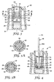
- FIG. 1 is an exterior perspective view of a single unit dose container 10 of a delivery system for a composition.
- container 10 includes outer housing 12, having outer skirt 14, and inner housing 16.
- a seal 17 is disposed over the outer housing 12 and inner housing 16.
- container 10 contains a composition used in dental, pharmaceutical and medical procedures. Examples of suitable compositions include dental adhesives, etchants, sealants and primers. As used herein, the word "dental" includes all fields of dentistry including orthodontic and endodontic treatment.
- outer skirt 14 is provided to enlarge container 10, thereby allowing for ease of handling.
- outer skirt 14 is contoured to fit comfortably between the fingers of a user.
- top section 18 and bottom section 20 each have a girth dimension which is greater than the girth dimension of middle section 22.
- outer skirt 14 is substantially cylindrical, and thus each girth dimension is a circumference.
- base 24 is flat and bottom section 20 is sufficiently wide to allow container 10 to rest stably upon a horizontal surface such as a countertop.
- FIG. 2 is an exterior perspective view of the embodiment of FIG. 1 , shown prior to assembly, with inner housing 16 removed from outer housing 12 along axis 25.
- Inner housing 16 includes one or more apertures 26 in a side wall thereof to allow for the flow of a composition component from outer housing 12 into inner housing 16. While outer housing 12 and inner housing 16 are illustrated as cylindrical members, it is contemplated that any slidably mating shapes may be used.
- FIG. 3 is a sectional view of the embodiment of FIG. 1 taken along line 3-3.
- Container 10 is designed to hold at least two masses of material separately from each other. This is especially useful for some dental compositions made of two or more components, for example, which should not be mixed until shortly before use.
- a first mass 28 of a first component of the composition is received within first chamber 30 of outer housing 12.
- a second mass 32 of a second component of the composition is received within second chamber 34 of inner housing 16.
- hermetic seal 17 is provided across a top surface of outer housing 12 and inner housing 16.
- stop member 38 is disposed within the first chamber 30 of outer housing 12 to establish a desired position of a bottom surface 39 of inner housing 16.
- stop member 38 is a radially inward projection such as an annular rib on an inner surface of outer housing 12.
- Outer housing 12 and inner housing 16 are preferably sized to produce an interference fit between outer housing 12 and inner housing 16 at interface 40.
- Container 10 is first assembled by providing outer housing 12 having outer skirt 14.
- outer housing 12 includes a hollow space 42 between core 44 and outer skirt 14 for savings in materials, costs, and weight.
- base 24 need not be one contiguous piece, but may consist of a base section for core 44 and a ring-shaped base section for outer skirt 14 where container 10 is cylindrical. It is contemplated that outer skirt 14, and thereby container 10, can also be formed in other shapes.
- First chamber 30 of outer housing 12 is at least partially filled with first mass 28 of a first component of the composition.
- Inner housing 16 is then inserted into outer housing 12.
- inner housing 16 is in a proper position once a bottom surface 39 of inner housing 16 contacts stop member 38. While stop member 38 is not required, it is useful for preventing inner housing 16 from being inserted too far into outer housing 12.
- An interference fit at interface 40 between outer housing 12 and inner housing 16 is adequate in one embodiment to seal first chamber 30 and prevent migration of the first mass of material 28 into second chamber 34 (or out of the container 10 along interface 40 between an inner wall of outer housing 12 and an outer wall of inner housing 16). The interference fit is also adequate to prevent the migration of material contained within second chamber 34 into first chamber 30.
- inner housing 16 has one or more apertures 26 in a side wall thereof.
- Second chamber 34 is at least partially filled with a second mass 32 of a second component of the composition, conforming in shape to a bottom and side wall of second chamber 34.
- first mass 28 consists of a liquid material
- second mass 32 consists of a material in liquid, semi-liquid such as a gel or paste, or solid form, for example. Even in solid form, it is preferable that the material of second mass 32 is in a flowable form such as a powder.
- the second mass of material 32 is introduced into second chamber 34, it fills apertures 26 as well as a bottom portion of second chamber 34.
- Seal 17 is provided over at least inner housing 16 to prevent escape of material from second chamber 34. As shown, a top surface of outer housing 12 is flush with a top surface of inner housing 16 and seal 17 also extends across the top surface of outer housing 12. In an exemplary embodiment, seal 17 is bonded to a top surface of outer housing 12 and to a top surface of inner housing 16. In an exemplary embodiment, seal 17 hermetically seals first mass 28 and second mass 32 within container 10. In an exemplary embodiment, seal 17 is a foil seal which can be broken in one or more manners, for example: by removing seal 17 by peeling it off container 10, or by rupturing seal 17 by the insertion of an object with manual force, preferably along axis 25, which is substantially perpendicular to an orientation of seal 17.
- container 10 hermetically sealed as shown, provides a container 10 for the separate component masses 28 and 32 which has a sufficiently long shelf life and is suitable for distribution and storage without the need for additional packaging (i.e., no additional foil sealed pouch is necessary for storage of container 10 or the components therein).
- inner housing 16 is cylindrical and each aperture 26 is a cylindrical bore.
- the apertures 26 are preferably equally spaced about a periphery of the side wall of inner housing 16 (see, e.g., FIG. 3A , where each aperture 26 is symmetrical about a radius of the cylinder of inner housing 16).
- the apertures 26 are parallel to one another (see, e.g., FIG. 3B ).
- Other numbers, shapes, orientations, and positions of aperture 26 can also be used.
- FIG. 4 is a sectional view of the embodiment of FIG. 3 , showing how container 10 is used to mix and dispense the component 28 and 32 masses.
- Inner housing 16 is pushed downward relative to the outer housing 12.
- Outer housing 12 and inner housing 16 are each preferably formed by injection molding a deformable or flexible material such as polypropylene, polyethylene, or cyclic olefin copolymer, for example.
- a deformable or flexible material such as polypropylene, polyethylene, or cyclic olefin copolymer, for example.
- the aforementioned housing plastics are particularly suitable materials since they allow for oxygen transfer, thereby resulting in longer shelf life, reduced requirements for stabilizers in the composition components, and smaller air volume requirements in container 10.
- Rod member 46 such as a composition applicator having a first end and a second end, is forced downward through seal 17, thereby breaking seal 17.
- Force from applicator 46 on second mass 32 and on inside surface 48 of inner housing 16 causes inner housing 16 to move downward relative to outer housing 12. Because of the seal between inner housing 16 and outer housing 12 at interface 40, this downward pressure causes the expansion of the walls of first chamber 30 or the deflection inward of the walls of second chamber 34, or both, resulting in the component mixing situation shown in FIG. 4 .
- the extent of expansion/contraction is exaggerated in FIG. 4 for purposes of illustration.
- the first mass of material 28 enters apertures 26 of inner housing 16 to mix with the second mass of material 32 therein.
- the pressurized situation causes turbulent jets of material from mass 28 to enter into second chamber 34, thereby producing an intensive mixing effect between the materials of both masses 28 and 32.
- second mass 32 consists of a solid material
- no stirring is necessary to fully mix the first mass 28 of the first component of the composition with the second mass 32 of the second component of the composition.
- the mixing is completed simply by forcing inner housing 16 all the way down into chamber 30 of outer housing12, resulting in mixed composition 49 within container 10 (see FIG. 5 ).
- applicator 46 may be agitated within second chamber 34 to facilitate such mixing as desired.
- applicator 46 includes elongated body 46A and tip 50 at a first end of the body 46A for application of mixed composition 49 to a desired surface.
- tip 50 of applicator 46 has a generally spherical configuration, although other shapes are possible.
- tip 50 includes a material or structure that facilitates spreading of mixed composition 49 material across the surface to which mixed composition 49 material is to be applied.
- Tip 50 may include any suitable materials and structures that are compatible with mixed composition 49 and function to distribute mixed composition 49 over the receiving surface. Suitable materials and structures include foam and sponge materials or bristles or fibers that serve as a brush and that are applied to all or only part of tip 50.
- FIG. 5 is a sectional view of the embodiment of FIG. 4 in a subsequent step, with inner housing 16 pushed down entirely into outer housing 12.
- inner housing 16 acts as a positive displacement piston and displaces substantially all of the air and material mass 28 of first chamber 30.
- all of the material of first mass 28 enters through apertures 26 to mix with the material of second mass 32 and thereby form mixed composition 49.
- mixed composition 49 is a homogenous compound made of two components, the first component provided by first mass 28 and the second component provided by second mass 32. In this manner, precise ratios of the first and second components of mixed composition 49 can be provided.
- second chamber 34 is large enough to hold the combined volume of first mass 28 and second mass 32.
- a chemical reaction occurs upon the mixing of the first component and the second component to form mixed composition 49, thereby resulting in a mixed composition 49 which is hardenable.
- Such a composition increases in hardness due to one or more influences, including for example, exposure to air, light, heat, or chemicals.
- Outer skirt 14 has a height greater than or equal to about 15 mm, less than or equal to about 30 mm, and preferably about 22 mm. Outer skirt 14 has a base 24 width greater than or equal to about 10 mm, less than or equal to about 30 mm, and preferably about 20 mm.
- Mixed composition 49 has a volume greater than or equal to about 50 microliters, less than or equal to about 300 microliters, and preferably about 120 microliters.
- Inner housing 16 has a diameter greater than or equal to about 3 mm, less than or equal to about 5 mm, and preferably about 4 mm. Inner housing 16 has a length greater than or equal to about 8 mm, less than or equal to about 20 mm, and preferably about 16 mm.
- Second chamber 34 of inner housing 16 has a volume greater than or equal to about 60 cubic mm, less than or equal to about 315 cubic mm, and preferably about 200 cubic mm.
- Outer housing 12 has an inner diameter greater than or equal to about 4 mm, less than or equal to about 7 mm, and preferably about 6 mm.
- First chamber 30 of outer housing 12 has a length greater than or equal to about 2 mm, less than or equal to about 5 mm, and preferably about 3.5 mm.
- First chamber 30 of outer housing 12 has a volume greater than or equal to about 30 cubic mm, less than or equal to about 150 cubic mm, and preferably about 100 cubic mm.
- Inner housing 16 includes about one or more apertures 26 and about ten or fewer apertures 26, and preferably about six apertures 26.
- Each aperture 26 is preferably a cylindrical bore having a diameter greater than or equal to about 0.5 mm, less than or equal to about 2.0 mm, and preferably about 1.0 mm. These dimensions and aperture numbers are provided as examples only; it is contemplated that container 10 can be made in any size suitable for a particular use or purpose.
- applicator 46 may be withdrawn so that mixed composition 49 material on tip 50 can be applied to a desired surface. It is preferable that tip 50 does not contact any other surface so as to prevent contamination. However, in some cases, fragments 53 of seal 17 may remain on a top surface of inner housing 16. Because the top surface of seal 17 has been exposed to the environment, it may be contaminated with bacteria, dirt or other undesirable contaminates. In the illustrated embodiment, great care must be taken to remove tip 50 without wiping mixed composition 49 on tip 50 with seal fragments 53 and without contaminating mixed composition 49 thereon.
- FIG. 6A is similar to FIG. 4 except that it shows an alternate embodiment of an applicator; applicator 54 includes projection 55 thereon along elongated body 46A of applicator 54.
- projection 55 passes through broken seal 17, projection 55 pushes fragments 53 of seal 17 toward the inner surface walls of inner housing 16 and away from axis 25.
- projection 55 is placed so that the widest part of projection 55 is no farther from a tip end of applicator 54 than the length of second chamber 34 of inner housing 16.
- Projection 55 has a girth dimension at a widest point which is greater than a girth dimension of body 46A.
- projection 55 is small enough to pass into second chamber 34 of inner housing 16.
- each girth dimension is a circumference.
- the girth dimension of projection 55 at a widest point is less than an inner diameter of inner housing 16.
- applicator 54 with projection 55 clears a larger area between fragments 53 of seal 17 for the extraction and reinsertion of tip 50 of applicator 54, thereby minimizing the chance of contamination of mixed composition 49 carried by tip 50.
- projection 55 is a symmetrical solid ellipse which is tapered on both sides.
- projection 55 can be of any shape having a girth dimension greater than a girth dimension of the elongated body 46A. Other shapes include, for example, disc, hemispherical, spherical, and cone shapes. While applicator 54 is useful with container 10 of the present invention, applicator 54 can also be used with any container having a rupturable seal at an opening of the container.
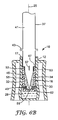
- FIG. 6B is similar to FIG. 4 except that it shows yet another alternate embodiment of an applicator.
- applicator 37 includes elongated body 41 having stop member 43 thereon. As illustrated, elongated body 41 interfaces with head 45 at shoulder 47.
- head 45 tapers from a girth larger dimension proximate shoulder 47 to a smaller girth dimension at tip 51.
- tip 51 has a sharp point to facilitate the breaking of seal 17.
- tip 51 has brush elements 52 disposed thereon in a spherical configuration.
- applicator 37 is generally cylindrical and is sized so that shoulder 47, rather than tip 51, is used to push inner housing 16 into outer housing 12; in that case, the length of tapered head 45 is less than or equal to the length of second chamber 34 of inner housing 16. With applicator 37, the insertion of inner housing 16 into outer housing 12 is more easily accomplished because the interface between shoulder 47 and the top surface of inner housing 16 provides for a larger surface area for the application of the pushing force, compared with the surface area of tip 50 of applicator 46 of FIG. 4 .
- tapered head 45 has a larger dimension proximate shoulder 47 to push seal fragments 53 toward the inner walls of inner housing 16 and a smaller dimension proximate tip 51.
- Tip 51 itself may be used for application of mixed composition 49 to a desired surface.
- tip 51 may include application elements such as a plurality of brush elements 52.
- stop member 43 is disposed about elongated body 41 and positioned so that a distance between shoulder 47 and stop member 43 is approximately equal to a distance between the top surfaces of inner housing 16 and outer housing 12 when inner housing 16 has been completely pushed into outer housing 12 (see FIG. 5 ). Thus, when stop member 43 contacts the top surface of outer housing 12, the contact signals to a user that complete mixing of component masses 28 and 32 has occurred to produce mixed composition 49.
- body 41 is hollow and one or more air vent slots 57 are disposed on tapered head 45 to allow for pressure release during the insertion of inner housing 16 into outer housing 12.
- head 45 may take on a different shape than illustrated.
- elongated body 41 may be narrower but include wider flanges or projections to serve as shoulder 47 and stop member 43.
- FIG. 7 illustrates a second embodiment of a container 60 of the present invention.
- FIG. 7A is an enlarged view of portion 7A in FIG. 7 .
- a seal 56 may be utilized.
- seal 56 is held within depression 58 proximate aperture 26.
- container 60 is assembled by at least partially filling first chamber 30 with a first mass 28 of a first component of a composition.
- Inner housing 16 is then inserted down into first chamber 30.
- Second chamber 34 is at least partially filled with a second mass 32 of a second component of the composition, conforming in shape to a bottom and side wall of second chamber 34.
- Seal 56 is movably disposed within depression 58 so that seal 56 can move between sealed and unsealed positions. As inner housing 16 is first pushed downward into outer housing 12, seal 56 naturally migrates to a top portion of depression 58 and is pushed downward as inner housing 16 is pushed downward. However, seal 56, to be effective, should prevent material or gas flow between aperture 26 and outer housing 12. In an embodiment including stop member 38, inner housing 16 is inserted until stop member 38 is contacted. Then, inner housing 16 is pulled back up to seat seal 56 at a bottom portion of depression 58 in order to seal the area between outer housing 12 and aperture 26. A bottom section of outer housing 12 can also be squeezed in order to force inner housing 16 up relative to outer housing 12. Therefore, inner housing 16 does not rest upon stop member 38 in this case.
- depression 58 includes a ramped wall 62, with the ramped wall 62 having a greater depth at a bottom portion of the wall than at a top portion of the wall.
- the directional terms “down” and “up” are used for purposes of explanation only, relative to the illustrated figures. The actual movement directions can of course be altered by changing the orientation of container 60.
- inner housing 16 is initially pushed down so that an upper surface of inner housing 16 is lower than an upper surface of outer housing 12. It is preferable that when inner housing 16 is pulled back up to seat seal 56, the upper surface of inner housing 16 is even with the upper surface of outer housing 12. Then, seal 17 can be provided over the upper surfaces of both inner housing 16 and outer housing 12.
- FIG. 8 shows the embodiment of FIG. 7 in a subsequent step, where mixing has occurred between component masses 28 and 32 to form mixed composition 49, with inner housing 16 pressed into outer housing 12.
- FIG. 8A is an enlarged view of portion 8A in FIG. 8 .
- seal 56 is an o-ring and depression 58 is an annular groove in an outer surface of inner housing 16.
- FIG. 9 illustrates a third embodiment of a container of the present invention.
- FIG. 9A is an enlarged view of portion 9A in FIG. 9 .
- Container 61 is similar to container 60 of FIG. 7 except that container 61 includes ramp member 63 to aid in the seating of seal 56 within depression 58.
- Ramp 63 may include a single ramp protrusion, multiple ramp protrusions, or a continuous ramp ridge disposed on an inner surface of chamber 30 of outer housing 12. Where multiple ramp protrusions are provided, it is preferable that they are disposed at equal intervals about an inner circumference of outer housing 12.
- Inner housing 16 is inserted so that a bottom surface of inner housing 16 moves onto the ramped surface of ramp 63, for example with the use of manual force.
- ramp 63 When the force is released, the shape of ramp 63 provides a spring effect, thereby pushing inner housing 16 back in a direction opposite from the direction of the applied force, and thereby seating seal 56 at a bottom portion of depression 58 in order to seal the area between outer housing 12 and aperture 26.
- the inclined surface of ramp 63 and/or seal 56 may be lubricated or otherwise treated to enhance the seating effect. It is important that inner housing 16 not be pushed in so far that ramp 63 falls into depression 58; in that case, inner housing 16 would not spring back relative to outer housing 12.
- Ramp 63 may be lengthened or provided with a stop member similar to stop member 38, for example, to prevent such an occurrence.
- stop member 38 for example
- FIG. 10 is an exterior perspective view of a fourth embodiment of the present invention, illustrating a double dose unit container.
- container 64 a single outer skirt 66 surrounds two sets of outer housings 12 and corresponding inner housings 16, with their respective composition component masses separated by seals therein.
- Such a container 64 would be useful, for example, where two mixed compositions 49 are applied alternately or in quick succession. It is contemplated that numerous such variations and configurations are within the scope of the invention.
Landscapes
- Health & Medical Sciences (AREA)
- Oral & Maxillofacial Surgery (AREA)
- Dentistry (AREA)
- Epidemiology (AREA)
- Life Sciences & Earth Sciences (AREA)
- Animal Behavior & Ethology (AREA)
- General Health & Medical Sciences (AREA)
- Public Health (AREA)
- Veterinary Medicine (AREA)
- Dental Tools And Instruments Or Auxiliary Dental Instruments (AREA)
- Containers And Packaging Bodies Having A Special Means To Remove Contents (AREA)
- Coating Apparatus (AREA)
- Infusion, Injection, And Reservoir Apparatuses (AREA)
- Details Of Rigid Or Semi-Rigid Containers (AREA)
Claims (27)
- Système de distribution d'une composition, le système comprenant un récipient (10, 60, 61), le récipient (10, 60, 61) comprenant :un boîtier externe (12) ayant une première chambre ;une première masse (28) d'un premier composant de la composition, la première masse (28) étant reçue dans la première chambre, le premier composant étant un liquide ;un boîtier interne (16) reçu dans la première chambre en une première position de telle sorte qu'il existe un ajustement serré entre le boîtier externe (12) et le boîtier interne (16), de telle sorte que le boîtier interne (16) scelle la première masse (28) à l'intérieur de la première chambre, le boîtier interne (16) ayant une deuxième chambre, le boîtier interne (16) ayant une ouverture (26) dans une paroi latérale de la deuxième chambre, et la deuxième chambre ayant une paroi inférieure et une paroi latérale ;une deuxième masse (32) d'un deuxième composant de la composition, la deuxième masse (32) étant reçue dans la deuxième chambre, et la deuxième masse épousant la forme de la paroi inférieure et de la paroi latérale ; etun premier joint (17) qui scelle la deuxième masse (32) à l'intérieur de la deuxième chambre, caractérisé en ce que le premier joint scelle la première masse (28) et la deuxième masse (32) à l'intérieur du récipient (10, 60, 61).
- Système de distribution selon la revendication 1, dans lequel le récipient comprend en outre un organe de butée (38) disposé sur le boîtier externe (12), un contact entre le boîtier interne (16) et l'organe de butée (38) se produisant à la première position.
- Système de distribution selon la revendication 2, dans lequel l'organe de butée (38) est une nervure annulaire.
- Système de distribution selon la revendication 1, dans lequel le premier joint (17) est un joint à film.
- Système de distribution selon la revendication 1, dans lequel le boîtier externe (12) comprend en outre une jupe externe (14) entourant la première chambre, la jupe (14) ayant une première dimension de pourtour dans une section supérieure de celle-ci, la jupe (14) ayant une deuxième dimension de pourtour dans une section inférieure de celle-ci, et la jupe ayant une troisième dimension de pourtour dans une section située entre la section supérieure et la section inférieure, la troisième dimension de pourtour étant inférieure à la première dimension de pourtour et la troisième dimension de pourtour étant inférieure à la deuxième dimension de pourtour.
- Système de distribution selon la revendication 1, dans lequel le récipient (60) comprend en outre :un renfoncement (58) dans une paroi externe du boîtier interne (16) à proximité de l'ouverture (26), etun deuxième joint (56) positionné à l'intérieur du renfoncement entre l'ouverture (26) et le boîtier externe (12).
- Système de distribution selon la revendication 6, dans lequel le renfoncement (58) a une première profondeur dans une section supérieure de celui-ci et une deuxième profondeur dans une section inférieure de celui-ci, la première profondeur étant inférieure à la deuxième profondeur.
- Système de distribution selon la revendication 6, dans lequel le deuxième joint (56) est un joint torique.
- Système de distribution selon la revendication 7, dans lequel le boîtier externe (12) comprend en outre une rampe (63).
- Système de distribution selon la revendication 1, dans lequel une paroi de la première ou de la deuxième chambre est flexible.
- Système de distribution selon la revendication 1, dans lequel le deuxième composant est un liquide ou un solide.
- Système de distribution selon la revendication 1, comprenant en outre un applicateur (54), l'applicateur (54) comprenant :un corps allongé (46A) ayant une première extrémité et une deuxième extrémité, le corps ayant une première dimension de pourtour ;une pointe d'applicateur (50) à la première extrémité du corps ; etune saillie (55) ayant un point le plus large positionné entre la première extrémité et la deuxième extrémité, la saillie ayant une deuxième dimension de pourtour au point le plus large supérieure à la première dimension de pourtour, chaque dimension de pourtour étant une circonférence.
- Système de distribution selon la revendication 12, dans lequel la deuxième chambre a une première dimension en longueur et une distance depuis la première extrémité du corps allongé (46A) au point le plus large de la saillie (55) est inférieure ou égale à la première dimension en longueur.
- Système de distribution selon la revendication 12, dans lequel le boîtier interne (16) a un diamètre intérieur et dans lequel la deuxième dimension de pourtour est inférieure au diamètre intérieur.
- Système de distribution selon la revendication 12, dans lequel la pointe d'applicateur (50) est une brosse.
- Système de distribution selon la revendication 1, comprenant en outre un applicateur (37), l'applicateur (37) comprenant :un corps allongé (41) ayant une première extrémité et une deuxième extrémité ;une tête (45) à la première extrémité du corps (41), la tête (45) ayant une première extrémité et une deuxième extrémité, la deuxième extrémité de la tête (45) étant à proximité de la première extrémité du corps (41), la tête (45) ayant une dimension de pourtour plus large à proximité de sa deuxième extrémité et une dimension de pourtour plus petite à proximité de sa première extrémité ; etune pointe (51) à la première extrémité de la tête,l'applicateur comprenant en outre :un épaulement (47) disposé au niveau d'une interface entre le corps (41) et la tête (45).
- Système de distribution selon la revendication 16, dans lequel l'applicateur (37) comprend en outre :un organe de butée (43) disposé sur le corps allongé (41), une distance de l'épaulement (47) à l'organe de butée (43) étant approximativement égale à une distance entre une surface supérieure du boîtier interne (16) et une surface supérieure du boîtier externe (12) lorsque le boîtier interne (16) est complètement inséré dans la première chambre du boîtier externe (12).
- Système de distribution selon la revendication 16, dans lequel l'applicateur (37) comprend en outre :une pluralité d'éléments de brosses disposés sur la pointe (51).
- Système de distribution selon la revendication 16, dans lequel le corps (41) est creux et la tête (45) comprend un évent d'air (57) disposé sur celle-ci.
- Système de distribution selon la revendication 1, dans lequel le premier joint (17) scelle en outre la première masse (28) à l'intérieur de la première chambre.
- Système de distribution selon la revendication 1, dans lequel le boîtier interne (16) comporte une pluralité d'ouvertures (26) dans la paroi latérale de la deuxième chambre, les ouvertures (26) étant espacées uniformément autour d'une périphérie de la paroi latérale.
- Système de distribution selon la revendication 1, dans lequel la composition est durcissable.
- Procédé pour assembler un récipient (10, 60, 61) pour une composition, comprenant les étapes consistant à :fournir un boîtier externe (12) ayant une première chambre ;remplir au moins en partie la première chambre avec une première masse (28) d'un premier composant de la composition, le premier composant étant un liquide ;insérer un boîtier interne (16) dans la première chambre jusqu'à ce que le boîtier interne (16) soit dans une première position, un ajustement serré existant entre le boîtier externe (12) et le boîtier interne (16) de telle sorte que le boîtier interne (16) scelle la première masse (28) à l'intérieur de la première chambre, le boîtier interne (16) ayant une deuxième chambre, la deuxième chambre ayant une paroi inférieure et une paroi latérale, et le boîtier interne (16) ayant une ouverture (26) dans une paroi latérale de la deuxième chambre ;remplir au moins en partie la deuxième chambre avec une deuxième masse (32) d'un deuxième composant de la composition, la deuxième masse (32) épousant la forme de la paroi inférieure et de la paroi latérale ; etsceller la deuxième masse (32) à l'intérieur de la deuxième chambre,caractérisé par l'étape consistant à sceller la première masse (28) et la deuxième masse (32) à l'intérieur du récipient (10, 60, 61).
- Procédé selon la revendication 23, dans lequel le boîtier externe (12) comprend en outre un organe de butée (38) et dans lequel l'étape consistant à insérer le boîtier interne (16) dans la première chambre inclut de faire coulisser le boîtier interne (16) dans la première chambre jusqu'à ce que le boîtier interne (16) vienne en contact avec l'organe de butée (38).
- Procédé selon la revendication 23, dans lequel le boîtier interne (16) comprend en outre un renfoncement (58) dans une paroi externe du boîtier interne (16) à proximité de l'ouverture (26), le procédé comprenant en outre les étapes consistant à :positionner un deuxième joint (56) à l'intérieur du renfoncement (58) avant d'insérer le boîtier interne (16) dans la première chambre dans une première direction, ettirer sur le boîtier interne (16) dans une deuxième direction opposée à la première direction pour ajuster le deuxième joint (56) entre l'ouverture (26) et le boîtier externe (12).
- Procédé pour fournir une composition, comprenant les étapes consistant à :fournir un récipient (10, 60, 61), le récipient comprenant :un boîtier externe (12) ayant une première chambre ;une première masse (28) d'un premier composant de la composition, la première masse (28) étant reçue dans la première chambre, le premier composant étant un liquide ;un boîtier interne (16) reçu dans la première chambre, le boîtier interne (16) ayant une deuxième chambre, la deuxième chambre ayant une paroi inférieure et une paroi latérale, et le boîtier interne (16) ayant une ouverture dans une paroi latérale de la deuxième chambre ;une deuxième masse (32) d'un deuxième composant de la composition, la deuxième masse (32) étant reçue dans la deuxième chambre, la deuxième masse (32) épousant la forme de la paroi inférieure et de la paroi latérale ;etun premier joint (17) qui scelle la deuxième masse à l'intérieur de la deuxième chambre,caractérisé par le faitque le premier joint scelle la première masse (28) et la deuxième masse (32) à l'intérieur du récipient (10, 60, 61) ;de casser le premier joint (17) en poussant vers le bas sur le joint avec un applicateur (54, 37), etde fournir une force sur le boîtier interne (16) en poussant vers le bas sur l'applicateur (54, 37), pour ainsi pousser le boîtier interne (16) dans le boîtier externe (12), une pression causée par la force forçant la première masse (28) à travers l'ouverture (26) et dans la deuxième chambre de manière à ce qu'elle se mélange avec la deuxième masse (32) pour former la composition.
- Procédé selon la revendication 26, comprenant en outre l'étape consistant à :agiter la composition avec l'applicateur (54, 37) pour mélanger davantage la première masse (28) et la deuxième masse (32).
Applications Claiming Priority (2)
| Application Number | Priority Date | Filing Date | Title |
|---|---|---|---|
| US10/798,649 US7131784B2 (en) | 2004-03-11 | 2004-03-11 | Unit dose delivery system |
| PCT/US2005/007012 WO2005089954A2 (fr) | 2004-03-11 | 2005-03-04 | Systeme de distribution de dose unitaire |
Publications (2)
| Publication Number | Publication Date |
|---|---|
| EP1722898A2 EP1722898A2 (fr) | 2006-11-22 |
| EP1722898B1 true EP1722898B1 (fr) | 2011-11-30 |
Family
ID=34920318
Family Applications (1)
| Application Number | Title | Priority Date | Filing Date |
|---|---|---|---|
| EP05724536A Not-in-force EP1722898B1 (fr) | 2004-03-11 | 2005-03-04 | Systeme de distribution de dose unitaire |
Country Status (9)
| Country | Link |
|---|---|
| US (2) | US7131784B2 (fr) |
| EP (1) | EP1722898B1 (fr) |
| JP (1) | JP4762227B2 (fr) |
| KR (1) | KR20060130725A (fr) |
| CN (1) | CN1942373B (fr) |
| AT (1) | ATE535313T1 (fr) |
| AU (1) | AU2005222573B2 (fr) |
| CA (1) | CA2559223A1 (fr) |
| WO (1) | WO2005089954A2 (fr) |
Families Citing this family (19)
| Publication number | Priority date | Publication date | Assignee | Title |
|---|---|---|---|---|
| EP1576933A1 (fr) * | 2004-03-11 | 2005-09-21 | 3M Espe Ag | Capsule pour le stockage , le mélange et la distribution de matériaux |
| EP1743849B1 (fr) * | 2005-07-15 | 2008-09-17 | Dentaco Dentalindustrie und -marketing GmbH | Dispositif pour stocker et délivrer une substance fluide |
| ATE454185T1 (de) * | 2005-11-03 | 2010-01-15 | Dentaco Gmbh | Appliziervorrichtung für eine fliessfähige substanz |
| US20070246381A1 (en) * | 2006-04-21 | 2007-10-25 | Pond Gary J | Telescoping ampoule device |
| FR2905241B1 (fr) * | 2006-08-29 | 2008-11-21 | Socoplan Soc Par Actions Simpl | Dose echantillon avec applicateur |
| DE102007039177B4 (de) * | 2007-08-20 | 2013-05-23 | Sulzer Mixpac Ag | Applikationsvorrichtung |
| DE202008004615U1 (de) * | 2007-11-26 | 2008-07-10 | Dentaco Dentalindustrie Und -Marketing Gmbh | Vorrichtung zum Applizieren eines pulverförmigen oder flüssigen Stoffes |
| WO2009114754A1 (fr) | 2008-03-14 | 2009-09-17 | Solutions Biomed, Llc | Système de contenant multichambre pour stocker et mélanger des fluides |
| US8087842B2 (en) * | 2008-06-30 | 2012-01-03 | Elc Management, Llc | Multi-compartment, wiper-applicator package |
| US20100081184A1 (en) * | 2008-09-26 | 2010-04-01 | Downey Robert A | Method for evaluation, design and optimization of in-situ bioconversion processes |
| WO2010056871A2 (fr) | 2008-11-12 | 2010-05-20 | Solutions Biomed, Llc | Système désinfectant en deux parties et procédés associés |
| US8789716B2 (en) | 2008-11-12 | 2014-07-29 | Solutions Biomed, Llc | Multi-chamber container system for storing and mixing liquids |
| AU2010349569B2 (en) * | 2010-03-25 | 2015-04-23 | Sdi Limited | Liquid container |
| DE102010037133A1 (de) | 2010-08-24 | 2012-03-01 | Fischerwerke Gmbh & Co. Kg | Behälter zum getrennten Aufbewahren von vor Gebrauch zu vermischenden Komponenten |
| US20130015188A1 (en) * | 2011-07-13 | 2013-01-17 | Joshua James Cheetham | Liquid container |
| EP2641562A1 (fr) * | 2012-11-26 | 2013-09-25 | Sulzer Mixpac AG | Système d'application pour un composant pouvant s'écouler |
| EP2754409B1 (fr) * | 2013-01-15 | 2020-12-16 | Ivoclar Vivadent AG | Four dentaire |
| US9925026B2 (en) * | 2014-07-21 | 2018-03-27 | Kerr Corporation | Adapters, tips, and dental assemblies |
| WO2020060532A1 (fr) | 2018-09-17 | 2020-03-26 | Halliburton Energy Services, Inc. | Joint d'étanchéité collé en deux parties pour des applications d'outil de fond de trou statiques |
Family Cites Families (19)
| Publication number | Priority date | Publication date | Assignee | Title |
|---|---|---|---|---|
| US2445477A (en) | 1945-03-12 | 1948-07-20 | Marvin L Folkman | Ampoule |
| US3279654A (en) | 1965-02-08 | 1966-10-18 | Richard L Pierick | Syringe |
| US3713780A (en) * | 1971-02-01 | 1973-01-30 | Becton Dickinson Co | Apparatus for chemical testing |
| DE3208786A1 (de) | 1982-03-11 | 1983-09-22 | Cassella Ag, 6000 Frankfurt | Zweikammerbehaeltnis mit zerstoerbarer trennwand |
| US5217433A (en) | 1991-05-24 | 1993-06-08 | Merck & Co., Inc. | Medication container for mixing two components |
| DE9215566U1 (de) | 1992-07-07 | 1993-11-11 | Ihde Stefan Prof Dr | Vollständig geschlossene Zweikomponenten-Mischkapsel, vorzugsweise für Zahnfüllstoffe |
| DE19706932A1 (de) | 1997-02-20 | 1998-08-27 | Dentaco Gmbh | Mehrkammer-Ampulle für portionierte Flüssigkeiten |
| CN2290567Y (zh) * | 1997-03-28 | 1998-09-09 | 董为 | 一体多层包装瓶 |
| DE29714246U1 (de) * | 1997-08-08 | 1998-12-10 | Thera Ges Fuer Patente | Vorrichtung zum Lagern und Auftragen einer fließfähigen Substanz |
| FR2767514B1 (fr) * | 1997-08-22 | 1999-11-05 | Dominique Mounier | Flacon melangeur mettant en contact deux composants isoles avant leur prelevement et leur injection a l'aide d'une seringue |
| WO2001032242A1 (fr) | 1999-11-03 | 2001-05-10 | Dentaco Dentalindustrie Und -Marketing Gmbh | Ampoule multichambre servant a distribuer un melange constitue de plusieurs substances |
| US6447476B1 (en) | 1999-11-19 | 2002-09-10 | Dentaco Dentalindustrie-Und Marketing Gmbh | Prefilled telescoping ampoule device |
| US6450717B1 (en) | 1999-11-25 | 2002-09-17 | Ivoclar Ag. | Applicator and method of applying |
| DE10029830B4 (de) | 2000-06-16 | 2008-04-10 | Voco Gmbh | Vorrichtung zum Lagern und Applizieren einer ein- oder mehrkomponentigen fließfähigen Substanz |
| DE20107507U1 (de) | 2000-11-02 | 2002-03-07 | Dentaco Gmbh | Ampulle zum Ausgeben einer Substanz oder eines aus mehreren Substanzen bestehenden Gemisches |
| EP1205196B1 (fr) | 2000-11-09 | 2006-06-14 | Dentaco Dentalindustrie und -marketing GmbH | Ampoule préremplie avec plusieurs chambres télescopiques |
| US6419414B1 (en) * | 2001-04-20 | 2002-07-16 | 3M Innovative Properties Company | Container for multiple-component compositions |
| US6543612B2 (en) | 2001-05-21 | 2003-04-08 | 3M Innovative Properties Company | Container for compositions made of two or more components |
| US7090491B2 (en) | 2002-11-12 | 2006-08-15 | Kerr Corporation | Single-dose dental adhesive delivery system and method |
-
2004
- 2004-03-11 US US10/798,649 patent/US7131784B2/en not_active Expired - Fee Related
-
2005
- 2005-03-04 WO PCT/US2005/007012 patent/WO2005089954A2/fr active Application Filing
- 2005-03-04 KR KR1020067021023A patent/KR20060130725A/ko not_active Application Discontinuation
- 2005-03-04 AT AT05724536T patent/ATE535313T1/de active
- 2005-03-04 CN CN200580011940XA patent/CN1942373B/zh not_active Expired - Fee Related
- 2005-03-04 JP JP2007502868A patent/JP4762227B2/ja not_active Expired - Fee Related
- 2005-03-04 AU AU2005222573A patent/AU2005222573B2/en not_active Ceased
- 2005-03-04 CA CA002559223A patent/CA2559223A1/fr not_active Abandoned
- 2005-03-04 EP EP05724536A patent/EP1722898B1/fr not_active Not-in-force
-
2006
- 2006-11-06 US US11/593,250 patent/US20070053736A1/en not_active Abandoned
Also Published As
| Publication number | Publication date |
|---|---|
| AU2005222573A1 (en) | 2005-09-29 |
| EP1722898A2 (fr) | 2006-11-22 |
| US20070053736A1 (en) | 2007-03-08 |
| KR20060130725A (ko) | 2006-12-19 |
| CN1942373A (zh) | 2007-04-04 |
| JP2007528267A (ja) | 2007-10-11 |
| US20050201813A1 (en) | 2005-09-15 |
| CN1942373B (zh) | 2010-09-29 |
| AU2005222573B2 (en) | 2009-10-22 |
| CA2559223A1 (fr) | 2005-09-29 |
| JP4762227B2 (ja) | 2011-08-31 |
| WO2005089954A3 (fr) | 2006-05-04 |
| US7131784B2 (en) | 2006-11-07 |
| ATE535313T1 (de) | 2011-12-15 |
| WO2005089954A2 (fr) | 2005-09-29 |
Similar Documents
| Publication | Publication Date | Title |
|---|---|---|
| EP1722898B1 (fr) | Systeme de distribution de dose unitaire | |
| EP1390275B1 (fr) | Receptacle pour compositions contenant au moins deux composants | |
| US8016161B2 (en) | Package and dispensing system | |
| US5871355A (en) | Dental mixing capsule for dispensing a multiple component dental material | |
| AU2011201857B2 (en) | Cartridge system and dispensing tube for said cartridge system | |
| US5392904A (en) | Mixing capsule for dental compositions | |
| EP2497440A1 (fr) | Dispositif pour distribution de matériau dentaire | |
| JPH06209955A (ja) | シリンジ装置 | |
| JP4271945B2 (ja) | 多成分組成物用の容器 | |
| US20120017412A1 (en) | Package and dispensing system | |
| US5746313A (en) | Mixing capsule and method of manufacturing same | |
| WO2009058343A1 (fr) | Conditionnement et système de distribution | |
| EP1815818B1 (fr) | Container | |
| EP1390274B1 (fr) | Conditionnement pour substance dentaire | |
| US20240058097A1 (en) | A dispensing gun for delivering a material from a cartridge |
Legal Events
| Date | Code | Title | Description |
|---|---|---|---|
| PUAI | Public reference made under article 153(3) epc to a published international application that has entered the european phase |
Free format text: ORIGINAL CODE: 0009012 |
|
| 17P | Request for examination filed |
Effective date: 20060920 |
|
| AK | Designated contracting states |
Kind code of ref document: A2 Designated state(s): AT BE BG CH CY CZ DE DK EE ES FI FR GB GR HU IE IS IT LI LT LU MC NL PL PT RO SE SI SK TR |
|
| AX | Request for extension of the european patent |
Extension state: AL BA HR LV MK YU |
|
| DAX | Request for extension of the european patent (deleted) | ||
| 17Q | First examination report despatched |
Effective date: 20091026 |
|
| GRAP | Despatch of communication of intention to grant a patent |
Free format text: ORIGINAL CODE: EPIDOSNIGR1 |
|
| GRAS | Grant fee paid |
Free format text: ORIGINAL CODE: EPIDOSNIGR3 |
|
| GRAA | (expected) grant |
Free format text: ORIGINAL CODE: 0009210 |
|
| AK | Designated contracting states |
Kind code of ref document: B1 Designated state(s): AT BE BG CH CY CZ DE DK EE ES FI FR GB GR HU IE IS IT LI LT LU MC NL PL PT RO SE SI SK TR |
|
| REG | Reference to a national code |
Ref country code: GB Ref legal event code: FG4D Ref country code: CH Ref legal event code: EP |
|
| REG | Reference to a national code |
Ref country code: IE Ref legal event code: FG4D |
|
| REG | Reference to a national code |
Ref country code: DE Ref legal event code: R096 Ref document number: 602005031459 Country of ref document: DE Effective date: 20120126 |
|
| REG | Reference to a national code |
Ref country code: NL Ref legal event code: VDEP Effective date: 20111130 |
|
| LTIE | Lt: invalidation of european patent or patent extension |
Effective date: 20111130 |
|
| PG25 | Lapsed in a contracting state [announced via postgrant information from national office to epo] |
Ref country code: LT Free format text: LAPSE BECAUSE OF FAILURE TO SUBMIT A TRANSLATION OF THE DESCRIPTION OR TO PAY THE FEE WITHIN THE PRESCRIBED TIME-LIMIT Effective date: 20111130 Ref country code: IS Free format text: LAPSE BECAUSE OF FAILURE TO SUBMIT A TRANSLATION OF THE DESCRIPTION OR TO PAY THE FEE WITHIN THE PRESCRIBED TIME-LIMIT Effective date: 20120330 |
|
| PG25 | Lapsed in a contracting state [announced via postgrant information from national office to epo] |
Ref country code: NL Free format text: LAPSE BECAUSE OF FAILURE TO SUBMIT A TRANSLATION OF THE DESCRIPTION OR TO PAY THE FEE WITHIN THE PRESCRIBED TIME-LIMIT Effective date: 20111130 Ref country code: GR Free format text: LAPSE BECAUSE OF FAILURE TO SUBMIT A TRANSLATION OF THE DESCRIPTION OR TO PAY THE FEE WITHIN THE PRESCRIBED TIME-LIMIT Effective date: 20120301 Ref country code: SE Free format text: LAPSE BECAUSE OF FAILURE TO SUBMIT A TRANSLATION OF THE DESCRIPTION OR TO PAY THE FEE WITHIN THE PRESCRIBED TIME-LIMIT Effective date: 20111130 Ref country code: SI Free format text: LAPSE BECAUSE OF FAILURE TO SUBMIT A TRANSLATION OF THE DESCRIPTION OR TO PAY THE FEE WITHIN THE PRESCRIBED TIME-LIMIT Effective date: 20111130 Ref country code: PT Free format text: LAPSE BECAUSE OF FAILURE TO SUBMIT A TRANSLATION OF THE DESCRIPTION OR TO PAY THE FEE WITHIN THE PRESCRIBED TIME-LIMIT Effective date: 20120330 Ref country code: BE Free format text: LAPSE BECAUSE OF FAILURE TO SUBMIT A TRANSLATION OF THE DESCRIPTION OR TO PAY THE FEE WITHIN THE PRESCRIBED TIME-LIMIT Effective date: 20111130 |
|
| PG25 | Lapsed in a contracting state [announced via postgrant information from national office to epo] |
Ref country code: CY Free format text: LAPSE BECAUSE OF FAILURE TO SUBMIT A TRANSLATION OF THE DESCRIPTION OR TO PAY THE FEE WITHIN THE PRESCRIBED TIME-LIMIT Effective date: 20111130 |
|
| PG25 | Lapsed in a contracting state [announced via postgrant information from national office to epo] |
Ref country code: CZ Free format text: LAPSE BECAUSE OF FAILURE TO SUBMIT A TRANSLATION OF THE DESCRIPTION OR TO PAY THE FEE WITHIN THE PRESCRIBED TIME-LIMIT Effective date: 20111130 Ref country code: BG Free format text: LAPSE BECAUSE OF FAILURE TO SUBMIT A TRANSLATION OF THE DESCRIPTION OR TO PAY THE FEE WITHIN THE PRESCRIBED TIME-LIMIT Effective date: 20120229 Ref country code: DK Free format text: LAPSE BECAUSE OF FAILURE TO SUBMIT A TRANSLATION OF THE DESCRIPTION OR TO PAY THE FEE WITHIN THE PRESCRIBED TIME-LIMIT Effective date: 20111130 Ref country code: SK Free format text: LAPSE BECAUSE OF FAILURE TO SUBMIT A TRANSLATION OF THE DESCRIPTION OR TO PAY THE FEE WITHIN THE PRESCRIBED TIME-LIMIT Effective date: 20111130 Ref country code: EE Free format text: LAPSE BECAUSE OF FAILURE TO SUBMIT A TRANSLATION OF THE DESCRIPTION OR TO PAY THE FEE WITHIN THE PRESCRIBED TIME-LIMIT Effective date: 20111130 |
|
| PG25 | Lapsed in a contracting state [announced via postgrant information from national office to epo] |
Ref country code: RO Free format text: LAPSE BECAUSE OF FAILURE TO SUBMIT A TRANSLATION OF THE DESCRIPTION OR TO PAY THE FEE WITHIN THE PRESCRIBED TIME-LIMIT Effective date: 20111130 Ref country code: PL Free format text: LAPSE BECAUSE OF FAILURE TO SUBMIT A TRANSLATION OF THE DESCRIPTION OR TO PAY THE FEE WITHIN THE PRESCRIBED TIME-LIMIT Effective date: 20111130 Ref country code: IT Free format text: LAPSE BECAUSE OF FAILURE TO SUBMIT A TRANSLATION OF THE DESCRIPTION OR TO PAY THE FEE WITHIN THE PRESCRIBED TIME-LIMIT Effective date: 20111130 |
|
| REG | Reference to a national code |
Ref country code: AT Ref legal event code: MK05 Ref document number: 535313 Country of ref document: AT Kind code of ref document: T Effective date: 20111130 |
|
| PLBE | No opposition filed within time limit |
Free format text: ORIGINAL CODE: 0009261 |
|
| STAA | Information on the status of an ep patent application or granted ep patent |
Free format text: STATUS: NO OPPOSITION FILED WITHIN TIME LIMIT |
|
| PG25 | Lapsed in a contracting state [announced via postgrant information from national office to epo] |
Ref country code: MC Free format text: LAPSE BECAUSE OF NON-PAYMENT OF DUE FEES Effective date: 20120331 |
|
| 26N | No opposition filed |
Effective date: 20120831 |
|
| GBPC | Gb: european patent ceased through non-payment of renewal fee |
Effective date: 20120304 |
|
| REG | Reference to a national code |
Ref country code: FR Ref legal event code: ST Effective date: 20121130 |
|
| REG | Reference to a national code |
Ref country code: DE Ref legal event code: R097 Ref document number: 602005031459 Country of ref document: DE Effective date: 20120831 |
|
| REG | Reference to a national code |
Ref country code: IE Ref legal event code: MM4A |
|
| PG25 | Lapsed in a contracting state [announced via postgrant information from national office to epo] |
Ref country code: FR Free format text: LAPSE BECAUSE OF NON-PAYMENT OF DUE FEES Effective date: 20120402 Ref country code: IE Free format text: LAPSE BECAUSE OF NON-PAYMENT OF DUE FEES Effective date: 20120304 Ref country code: GB Free format text: LAPSE BECAUSE OF NON-PAYMENT OF DUE FEES Effective date: 20120304 Ref country code: AT Free format text: LAPSE BECAUSE OF FAILURE TO SUBMIT A TRANSLATION OF THE DESCRIPTION OR TO PAY THE FEE WITHIN THE PRESCRIBED TIME-LIMIT Effective date: 20111130 |
|
| PG25 | Lapsed in a contracting state [announced via postgrant information from national office to epo] |
Ref country code: ES Free format text: LAPSE BECAUSE OF FAILURE TO SUBMIT A TRANSLATION OF THE DESCRIPTION OR TO PAY THE FEE WITHIN THE PRESCRIBED TIME-LIMIT Effective date: 20120311 |
|
| PGFP | Annual fee paid to national office [announced via postgrant information from national office to epo] |
Ref country code: CH Payment date: 20130312 Year of fee payment: 9 Ref country code: DE Payment date: 20130227 Year of fee payment: 9 |
|
| PG25 | Lapsed in a contracting state [announced via postgrant information from national office to epo] |
Ref country code: FI Free format text: LAPSE BECAUSE OF FAILURE TO SUBMIT A TRANSLATION OF THE DESCRIPTION OR TO PAY THE FEE WITHIN THE PRESCRIBED TIME-LIMIT Effective date: 20111130 |
|
| PG25 | Lapsed in a contracting state [announced via postgrant information from national office to epo] |
Ref country code: TR Free format text: LAPSE BECAUSE OF FAILURE TO SUBMIT A TRANSLATION OF THE DESCRIPTION OR TO PAY THE FEE WITHIN THE PRESCRIBED TIME-LIMIT Effective date: 20111130 |
|
| PG25 | Lapsed in a contracting state [announced via postgrant information from national office to epo] |
Ref country code: LU Free format text: LAPSE BECAUSE OF NON-PAYMENT OF DUE FEES Effective date: 20120304 |
|
| PG25 | Lapsed in a contracting state [announced via postgrant information from national office to epo] |
Ref country code: HU Free format text: LAPSE BECAUSE OF FAILURE TO SUBMIT A TRANSLATION OF THE DESCRIPTION OR TO PAY THE FEE WITHIN THE PRESCRIBED TIME-LIMIT Effective date: 20050304 |
|
| REG | Reference to a national code |
Ref country code: DE Ref legal event code: R119 Ref document number: 602005031459 Country of ref document: DE |
|
| REG | Reference to a national code |
Ref country code: CH Ref legal event code: PL |
|
| REG | Reference to a national code |
Ref country code: DE Ref legal event code: R119 Ref document number: 602005031459 Country of ref document: DE Effective date: 20141001 |
|
| PG25 | Lapsed in a contracting state [announced via postgrant information from national office to epo] |
Ref country code: CH Free format text: LAPSE BECAUSE OF NON-PAYMENT OF DUE FEES Effective date: 20140331 Ref country code: DE Free format text: LAPSE BECAUSE OF NON-PAYMENT OF DUE FEES Effective date: 20141001 Ref country code: LI Free format text: LAPSE BECAUSE OF NON-PAYMENT OF DUE FEES Effective date: 20140331 |