EP1722611A2 - Elektronisches Gerät mit einer elektrischen Spule - Google Patents
Elektronisches Gerät mit einer elektrischen Spule Download PDFInfo
- Publication number
- EP1722611A2 EP1722611A2 EP06007437A EP06007437A EP1722611A2 EP 1722611 A2 EP1722611 A2 EP 1722611A2 EP 06007437 A EP06007437 A EP 06007437A EP 06007437 A EP06007437 A EP 06007437A EP 1722611 A2 EP1722611 A2 EP 1722611A2
- Authority
- EP
- European Patent Office
- Prior art keywords
- electronic device
- coil
- winding
- electrical coil
- bobbin
- Prior art date
- Legal status (The legal status is an assumption and is not a legal conclusion. Google has not performed a legal analysis and makes no representation as to the accuracy of the status listed.)
- Granted
Links
Images
Classifications
-
- H—ELECTRICITY
- H05—ELECTRIC TECHNIQUES NOT OTHERWISE PROVIDED FOR
- H05K—PRINTED CIRCUITS; CASINGS OR CONSTRUCTIONAL DETAILS OF ELECTRIC APPARATUS; MANUFACTURE OF ASSEMBLAGES OF ELECTRICAL COMPONENTS
- H05K1/00—Printed circuits
- H05K1/02—Details
- H05K1/0201—Thermal arrangements, e.g. for cooling, heating or preventing overheating
- H05K1/0203—Cooling of mounted components
-
- H—ELECTRICITY
- H01—ELECTRIC ELEMENTS
- H01F—MAGNETS; INDUCTANCES; TRANSFORMERS; SELECTION OF MATERIALS FOR THEIR MAGNETIC PROPERTIES
- H01F27/00—Details of transformers or inductances, in general
- H01F27/02—Casings
- H01F27/027—Casings specially adapted for combination of signal type inductors or transformers with electronic circuits, e.g. mounting on printed circuit boards
-
- H—ELECTRICITY
- H01—ELECTRIC ELEMENTS
- H01F—MAGNETS; INDUCTANCES; TRANSFORMERS; SELECTION OF MATERIALS FOR THEIR MAGNETIC PROPERTIES
- H01F27/00—Details of transformers or inductances, in general
- H01F27/06—Mounting, supporting, or suspending transformers, reactors, or choke coils not being of the signal type
- H01F27/065—Mounting on printed circuit boards
-
- H—ELECTRICITY
- H01—ELECTRIC ELEMENTS
- H01F—MAGNETS; INDUCTANCES; TRANSFORMERS; SELECTION OF MATERIALS FOR THEIR MAGNETIC PROPERTIES
- H01F27/00—Details of transformers or inductances, in general
- H01F27/08—Cooling; Ventilating
- H01F27/22—Cooling by heat conduction through solid or powdered fillings
-
- H—ELECTRICITY
- H01—ELECTRIC ELEMENTS
- H01F—MAGNETS; INDUCTANCES; TRANSFORMERS; SELECTION OF MATERIALS FOR THEIR MAGNETIC PROPERTIES
- H01F27/00—Details of transformers or inductances, in general
- H01F27/08—Cooling; Ventilating
- H01F27/085—Cooling by ambient air
-
- H—ELECTRICITY
- H05—ELECTRIC TECHNIQUES NOT OTHERWISE PROVIDED FOR
- H05K—PRINTED CIRCUITS; CASINGS OR CONSTRUCTIONAL DETAILS OF ELECTRIC APPARATUS; MANUFACTURE OF ASSEMBLAGES OF ELECTRICAL COMPONENTS
- H05K1/00—Printed circuits
- H05K1/18—Printed circuits structurally associated with non-printed electric components
-
- H—ELECTRICITY
- H05—ELECTRIC TECHNIQUES NOT OTHERWISE PROVIDED FOR
- H05K—PRINTED CIRCUITS; CASINGS OR CONSTRUCTIONAL DETAILS OF ELECTRIC APPARATUS; MANUFACTURE OF ASSEMBLAGES OF ELECTRICAL COMPONENTS
- H05K2201/00—Indexing scheme relating to printed circuits covered by H05K1/00
- H05K2201/10—Details of components or other objects attached to or integrated in a printed circuit board
- H05K2201/10613—Details of electrical connections of non-printed components, e.g. special leads
- H05K2201/10621—Components characterised by their electrical contacts
- H05K2201/10659—Different types of terminals for the same component, e.g. solder balls combined with leads
Definitions
- the invention relates to an electronic device with an electric coil, which is arranged on a component reservoir.
- An electronic device comprises at least one electrical coil which is arranged on a component reservoir.
- An essential idea of the invention is that the electronic device has means which are designed such that a heat generated by the electric coil can be derived from this electrical coil via the component reservoir.
- the heat generated during operation of the electronic device, in particular during operation of the electric coil can be dissipated in an optimized manner.
- the means are designed and arranged such that a heat transfer from the coil via the component reservoir, the heat transfer can be relatively efficient, whereby overheating of the electrical coil or adjacent components can be prevented.
- the means are designed such that the temperature of the electric coil during operation by at least a value of 3 ° C, in particular by one value from 5 ° C to 10 ° C, is reducible.
- the means are thus designed such that they preferably effect such a temperature reduction of the electrical coil or of the electronic device, which prevent damage or impairment of the operation of the electronic device during operation.
- these means are also designed such that they are designed with regard to an optimized temperature reduction, an optimized cost structure and an optimized space requirement.
- the electric coil is designed as a choke coil and a coil body of the choke coil is formed of a thermally conductive material. It can thereby be achieved that a relatively good heat transfer of the heat generated during operation of the choke coil can be made possible by the coil material itself.
- the thermal conductivity of the material of the bobbin is greater than or equal to 1W / mK. Such materials allow a relatively rapid removal of heat generated.
- metal pins are formed at the free terminals of the electrical coil, wherein the electrical coil is mechanically connected by means of the metal pins with the component reservoir. This allows an improved heat transfer can be achieved again and the heat from the bobbin can be better transferred to the component reservoir.
- the component reservoir is preferably designed as a circuit board.
- a first winding for electrical function of the electric coil and at least one additional winding to the bobbin which is designed for heat transfer from the coil to the component reservoir and is without electrical function.
- at least two windings are arranged around the bobbin, wherein one is required for the electrical function of the coil and the second is without such an electrical function and is designed only for heat transfer from the heat generated by the electric coil in operation to the component reservoir.
- the additional winding is arranged adjacent to the first winding around the bobbin. It can also be provided that the additional winding is arranged in addition to or instead of the adjacent arrangement to the first winding at least partially on the first winding.
- arranging the first and the second winding can be carried out in a versatile and flexible manner, depending on the situation.
- a further advantageous embodiment of the electronic device according to the invention has a heat transfer element, which is at least partially disposed about a first winding of the electric coil, wherein this first winding for the electrical function of the electric coil is required.
- the heat transport element can thus be dissipated to the component reservoir in an efficient manner, the heat generated during operation of the electrical coil.
- the heat transfer element is at least partially formed on the first winding.
- the heat transfer element is mechanically connected to the component reservoir, in particular with a solder joint is attached to the component reservoir. This ensures on the one hand a mechanically particularly stable arrangement and on the other hand allows a particularly effective and efficient heat transfer to the component reservoir.
- the heat transfer element is advantageously designed as a metal sheet.
- the heat transfer element has at least one cooling element which extends at least partially in the horizontal direction next to the electrical coil and is arranged at a distance from the component reservoir.
- the electronic device according to the invention is designed as an electronic ballast, which is designed in particular for lamps, in particular for fluorescent lamps.
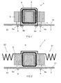
- FIG. 1 shows a cross-sectional view of a first exemplary embodiment of an electronic device according to the invention.
- the electronic device is formed in this embodiment as an electronic ballast 1 for fluorescent lamps.
- the electronic ballast 1 is arranged on a in the embodiment designed as a board 2 component reservoir.
- the electronic ballast 1 has a choke coil, which in the exemplary embodiment has a bobbin 3, which is arranged on the upper side 21 of the circuit board 2.
- the bobbin 3 is formed in the embodiment of a thermally conductive material having a thermal conductivity of at least 1 W / mK.
- the free terminals of the choke coil are provided with metal pins 4 and 5, which project through recesses in the circuit board 2 and are mechanically fixed on the underside 22 of the circuit board 2 by means of soldered connections 4a and 5a connected to the board 2.
- the bobbin 3 is firmly connected to the board 2.
- the bobbin 3 or the choke coil is at least partially surrounded by an element 6, which in the exemplary embodiment is formed from ferrite.
- the electronic ballast 1 or the choke coil comprises a first winding, not shown, which is required for the operating principle of the choke coil. This first winding thus has an electrical function.
- the choke coil comprises at least one second winding 7, which is wound around the bobbin and is designed as an additional winding. This additional winding or second winding 7 has no electrical function and serves to dissipate heat generated during operation of the inductor to the board 2.
- the additional winding or the second winding 7 may be wound around the bobbin adjacent to the first winding. However, it can also be provided that the second winding 7 is arranged in addition to or instead of an adjacent arrangement to the first winding at least partially on the first winding.
- a heat transfer element 8a designed as a metal sheet is furthermore arranged in the exemplary embodiment according to FIG.
- the heat transport element 8a is arranged like a hood around the second winding 7 and at least partially around the bobbin 3 of the choke coil.
- the heat transfer element 8a is thus at least partially integrally formed on the second winding 7.
- the heat transfer element 8a is passed with its free ends through recesses in the board 2 and attached to the bottom 22 of the board 2 with solder joints 8a and 8b.
- the free ends of the heat transport element 8 are bent over and oriented essentially parallel to the underside 22 of the board 2. These two bent regions are oriented such that they are formed facing each other.
- an optimized heat transfer in the electronic ballast 1 can be achieved.
- several alternatives of means according to the invention for heat transfer from the inductor to the board are formed. These means comprise in the embodiment in Figure 1 on the one hand one of a thermally conductive material existing bobbin 3, moreover provided with metal pins 4 and 5 free connections of the choke coil, as well as other alternatives, the second winding 7 and the heat transport element 8. It should be noted that each of these four alternatives by itself already improved and inventive heat transfer from the Throttle towards the board 2 allows.
- the means according to the invention for heat transport from the choke coil to the circuit board 2 can be made possible by any combination of the four alternatives according to the invention mentioned in the exemplary embodiment according to FIG. As already mentioned, in this regard each alternative alone can already realize the inventive concept.
- any combination of two but also three of the alternatives formed in the exemplary embodiment according to FIG. 1 may be provided in an electronic ballast 1.
- the bobbin 3 is made of a thermally conductive material and as a second alternative, only one heat transport element 8 is arranged.
- the bobbin 3 with metal pins 4 and 5 provided with free terminals and further arranged a trained without electrical function second winding 7 for heat transfer. Further combinations can be generated from the four alternatives realized in FIG.
- FIG. 2 shows a cross-sectional illustration of a second exemplary embodiment of an electronic device according to the invention with an electrical coil.
- the electronic device is designed as an electronic ballast 1.
- the electronic ballast 1 has a heat transport element 9.
- this heat transport element 9 has no mechanical connection to the board 2.
- the heat transport element 9 extends above the second winding 7 and the bobbin 3 and the ferrite element 6.
- the heat transfer element 9 is only in the central region in the upper region of the second winding 7 to the second winding. 7 formed.
- the heat transfer element 9 has a first cooling element 91 and a second cooling element 92 on the side of the choke coil or of the bobbin 3 and of the ferrite element 6.
- the cooling elements 91 and 92 are serrated in their cross-sectional representation.
- the cooling elements 91 and 92 allow heat transfer from the bobbin 3 to the environment. Thereby can be achieved that in addition to the heat transfer from the bobbin 3 and the choke coil to the board 2, a heat transfer from the choke coil or from the bobbin 3 via the heat transport element 9 and the cooling elements 91 and 92 takes place to the environment.
- the temperature of the electric coil or the choke coil of the electronic ballast 1 in operation by a value of 3 ° C to 12 ° C, in particular by a value of 5 ° C to 10 ° C can be reduced .
- Such a temperature reduction is optimal in two respects, because the means are designed such that they allow a cost-effective and space-saving implementation for a temperature reduction of the electrical coil or the electronic device and on the other hand, the temperature reduction takes place substantially to such a value that a Overheating and thus damaging or destroying the components of the electronic device and thus the electronic device itself can be prevented.
Landscapes
- Engineering & Computer Science (AREA)
- Power Engineering (AREA)
- Microelectronics & Electronic Packaging (AREA)
- Coils Or Transformers For Communication (AREA)
- Arrangement Of Elements, Cooling, Sealing, Or The Like Of Lighting Devices (AREA)
- Reciprocating, Oscillating Or Vibrating Motors (AREA)
- Coils Of Transformers For General Uses (AREA)
- Cooling Or The Like Of Electrical Apparatus (AREA)
- General Induction Heating (AREA)
Abstract
Description
- Die Erfindung betrifft ein elektronisches Gerät mit einer elektrischen Spule, welche auf einem Bauteilereservoir angeordnet ist.
- Bei bekannten elektronischen Geräten, insbesondere elektronischen Vorschaltgeräten, welche zumindest eine elektrische Spule aufweisen, ist es stets ein erstrebenswertes Ziel eine Verkleinerung derartiger Geräte durchführen zu können. Durch eine derartige zunehmende Miniaturisierung von elektronischen Vorschaltgeräten werden die leistungsübertragenden Komponenten thermisch immer stärker belastet. Auch die in diesen elektronischen Vorschaltgeräten enthaltenen Induktivitäten erreichen immer höhere Betriebstemperaturen, wodurch ein Kühlen dieser Induktivitäten bzw. eine Wärmereduzierung bei diesen Induktivitäten erforderlich ist, um eine Beschädigung oder Zerstörung der elektronischen Vorschaltgeräte vermeiden zu können.
- Es ist bekannt, dass derartige Induktivitäten beispielsweise durch eine Vergussmasse gekühlt werden. Ein wesentlicher Nachteil einer derartigen Vorgehensweise sind die damit verbundenen relativ hohen Kosten. Ein weiterer Nachteil dieser Lösung ist darin zu sehen, dass die mechanische Belastung der Lötstellen, die abhängig von der Vergussmasse beim Durchlaufen von Temperaturzyklen auftreten können. Eine weitere Alternative, thermische Belastungen bei elektronischen Vorschaltgeräten, insbesondere bei den Induktivitäten reduzieren bzw. in den Griff bekommen zu können, ist durch ein Anbringen von Wärmeleitmatten gegeben. Diese Wärmeleitmatten sind derart ausgebildet, dass sie die entstehende Wärme auf naheliegende Gehäuseteile übertragen sollen. Auch diese Lösung ist mit relativ hohen Kosten verbunden. Des Weiteren tritt auch hier das Problem der mechanischen Belastung der Lötstellen auf. Des Weiteren ist es bekannt, Induktivitäten bzw. Drosselspulen mit Lüftervorrichtungen zu kühlen. Auch diese Lösung ist relativ kostenintensiv und weist darüber hinaus auch noch die Nachteile auf, dass eine erhebliche Geräuschentwicklung vorhanden ist und gegebenenfalls eine reduzierte Lebensdauer einhergeht.
- Daher ist es Aufgabe der vorliegenden Erfindung ein elektronisches Gerät mit einer elektrischen Spule zu schaffen, bei welchem ein Überhitzen der Bauteile verhindert werden kann und dadurch eine Beschädigung oder Zerstörung des elektronischen Geräts vermieden werden kann. Diese Aufgabe wird durch ein elektronisches Gerät, welches die Merkmale nach Patentanspruch 1 aufweist, gelöst.
- Ein erfindungsgemäßes elektronisches Gerät umfasst zumindest eine elektrische Spule, welche auf einem Bauteilereservoir angeordnet ist. Ein wesentlicher Gedanke der Erfindung besteht darin, dass das elektronische Gerät Mittel aufweist, welche derart ausgebildet sind, dass eine von der elektrischen Spule erzeugte Wärme von dieser elektrischen Spule über das Bauteilereservoir ableitbar ist. Mit dem erfindungsgemäßen elektronischen Gerät kann erreicht werden, dass die beim Betrieb des elektronischen Geräts, insbesondere beim Betrieb der elektrischen Spule, erzeugte Wärme in optimierter Weise abgeführt werden kann. Indem erfindungsgemäß die Mittel derart ausgebildet und angeordnet sind, dass ein Wärmetransport von der Spule über das Bauteilereservoir erfolgt, kann der Wärmetransport relativ effizient erfolgen, wodurch ein Überhitzen der elektrischen Spule bzw. benachbarter Bauelemente verhindert werden kann. Dadurch kann auch bei immer kleiner ausgebildeten elektronischen Geräten, bei denen die Bauteile immer näher zueinander angeordnet sind, ein Beschädigen oder Zerstören aufgrund einer Überhitzung verhindert werden. Darüber hinaus kann durch die erfindungsgemäße Ausgestaltung des elektronischen Geräts eine relativ kostengünstige Realisierung eines effizienten Wärmetransports bereitgestellt werden. Ferner kann auch eine mechanische Belastung der Lötstellen vermindert bzw. ausgeschlossen werden und eine Geräuschentwicklung, wie dies im Stand der Technik mit einer Lüfterkühlung auftritt, vermieden werden.
- In vorteilhafter Weise sind die Mittel derart ausgebildet, dass die Temperatur der elektrischen Spule im Betrieb um mindestens einen Wert von 3°C, insbesondere um einen Wert von 5 °C bis 10°C, reduzierbar ist. Die Mittel sind somit derart ausgebildet, dass sie in bevorzugter Weise eine derartige Temperaturreduzierung der elektrischen Spule bzw. des elektronischen Geräts bewirken, welche ein Beschädigen oder Beeinträchtigen der Betriebsweise des elektronischen Geräts im Betrieb verhindern. Darüber hinaus sind diese Mittel auch derart ausgebildet, dass sie im Hinblick auf eine optimierte Temperaturreduzierung, eine optimierte Kostengestaltung sowie einen optimierten Platzbedarf ausgebildet sind.
- In einer vorteilhaften Ausgestaltung ist die elektrische Spule als Drosselspule ausgebildet und ein Spulenkörper der Drosselspule ist aus einem wärmeleitfähigen Material ausgebildet. Dadurch kann erreicht werden, dass durch das Spulenmaterial selbst ein relativ guter Wärmetransport der beim Betrieb der Drosselspule erzeugten Wärme ermöglicht werden kann. In vorteilhafter Weise ist die Wärmeleitfähigkeit des Materials des Spulenkörpers größer oder gleich 1W/mK. Derartige Materialen erlauben eine relativ schnelle Abfuhr der erzeugten Wärme.
- Es kann vorgesehen sein, dass an den freien Anschlüssen der elektrischen Spule Metallpins ausgebildet sind, wobei die elektrische Spule mittels der Metallpins mit dem Bauteilereservoir mechanisch verbunden ist. Dadurch kann nochmals eine verbesserte Wärmeübertragung erreicht werden und die Wärme vom Spulenkörper kann besser auf das Bauteilereservoir übertragen werden. Das Bauteilereservoir ist in bevorzugter Weise als Platine ausgebildet.
- In einer weiteren vorteilhaften Ausgestaltung der Erfindung kann um den Spulenkörper eine erste Wicklung zur elektrischen Funktion der elektrischen Spule und zumindest eine Zusatzwicklung um den Spulenkörper angeordnet sein, welche zum Wärmetransport von der Spule zum Bauteilereservoir ausgebildet ist und ohne elektrische Funktion ist. Somit sind um den Spulenkörper zumindest zwei Wicklungen angeordnet, wobei eine zur elektrischen Funktion der Spule erforderlich ist und die zweite ohne eine derartige elektrische Funktion ist und lediglich zum Wärmetransport von der durch die elektrische Spule im Betrieb erzeugten Wärme zum Bauteilereservoir ausgebildet ist.
- Es kann vorgesehen sein, dass die Zusatzwicklung benachbart zur ersten Wicklung um den Spulenkörper angeordnet ist. Es kann auch vorgesehen sein, dass die Zusatzwicklung zusätzlich oder anstatt der benachbarten Anordnung zur ersten Wicklung zumindest teilweise auf der ersten Wicklung angeordnet ist. In vielfältiger und flexibler Weise kann somit situationsabhängig und abhängig von der jeweils erforderlichen Ausgestaltung des elektronischen Geräts sowie der elektrischen Spule ein Anordnen der ersten und der zweiten Wicklung durchgeführt werden.
- Eine weitere vorteilhafte Ausgestaltung des erfindungsgemäßen elektronischen Geräts weist ein Wärmetransportelement auf, welches zumindest teilweise um eine erste Wicklung der elektrischen Spule angeordnet ist, wobei diese erste Wicklung zur elektrischen Funktion der elektrischen Spule erforderlich ist. Mittels dem Wärmetransportelement kann somit in effizienter Weise die beim Betrieb der elektrischen Spule erzeugte Wärme an das Bauteilereservoir abgeführt werden. Es kann vorgesehen sein, dass das Wärmetransportelement zumindest teilweise an die erste Wicklung angeformt ist. Dadurch kann einerseits erreicht werden, dass in optimaler Weise ein Wärmetransport durchgeführt werden kann und darüber hinaus ein möglichst geringer Platzbedarf für das Wärmetransportelement erforderlich ist.
- Es kann darüber hinaus vorgesehen sein, dass das Wärmetransportelement mit dem Bauteilereservoir mechanisch verbunden ist, insbesondere mit einer Lötverbindung an dem Bauteilereservoir befestigt ist. Dies gewährleistet einerseits eine mechanisch besonders stabile Anordnung und ermöglicht andererseits eine besonders effektive und effiziente Wärmeübertragung an das Bauteilereservoir. Das Wärmetransportelement ist in vorteilhafter Weise als Metallblech ausgebildet.
- Es kann des Weiteren vorgesehen sein, dass das Wärmetransportelement zumindest ein Kühlelement aufweist, welches sich zumindest teilweise in horizontaler Richtung neben der elektrischen Spule erstreckt und beabstandet zum Bauteilereservoir angeordnet ist.
- In vorteilhafter Ausführung ist das erfindungsgemäße elektronische Gerät als elektronisches Vorschaltgerät ausgebildet, welches insbesondere für Lampen, insbesondere für Leuchtstofflampen, ausgebildet ist.
- Ausführungsbeispiele der Erfindung werden nachfolgend anhand schematischer Zeichnungen näher erläutert. Es zeigen:
- Figur 1
- eine Schnittdarstellung durch ein erstes Ausführungsbeispiel eines erfindungsgemäßen elektronischen Geräts; und
- Figur 2
- eine Schnittdarstellung eines zweiten Ausführungsbeispiels eines erfindungsgemäßen elektronischen Geräts.
- In den Figuren werden gleiche oder funktionsgleiche Elemente mit den selben Bezugszeichen versehen.
- In Figur 1 ist eine Querschnittdarstellung eines ersten Ausführungsbeispiels eines erfindungsgemäßen elektronischen Geräts gezeigt. Das elektronische Gerät ist in diesem Ausführungsbeispiel als elektronisches Vorschaltgerät 1 für Leuchtstofflampen ausgebildet. Das elektronische Vorschaltgerät 1 ist auf einem im Ausführungsbeispiel als Platine 2 ausgebildeten Bauteilereservoir angeordnet. Das elektronische Vorschaltgerät 1 weist eine Drosselspule auf, welche im Ausführungsbeispiel einen Spulenkörper 3 aufweist, welcher auf der Oberseite 21 der Platine 2 angeordnet ist. Der Spulenkörper 3 ist im Ausführungsbeispiel aus einem wärmeleitfähigen Material ausgebildet, welches eine Wärmeleitfähigkeit von mindestens 1 W/mK aufweist. Wie des Weiteren aus der Darstellung in Figur 1 zu erkennen ist, sind die freien Anschlüsse der Drosselspule mit Metallpins 4 und 5 versehen, welche durch Aussparungen in der Platine 2 hindurchragen und auf der Unterseite 22 der Platine 2 mittels Lötverbindungen 4a bzw. 5a mechanisch fest mit der Platine 2 verbunden sind. Diesbezüglich ist auch der Spulenkörper 3 fest mit der Platine 2 verbunden.
- Wie des Weiteren aus der Darstellung in Figur 1 zu erkennen ist, ist der Spulenkörper 3 bzw. die Drosselspule zumindest teilweise von einem Element 6 umgeben, welches im Ausführungsbeispiel aus Ferrit ausgebildet ist. Das elektronische Vorschaltgerät 1 bzw. die Drosselspule umfasst eine nicht dargestellte erste Wicklung, welche für das Funktionsprinzip der Drosselspule erforderlich ist. Diese erste Wicklung hat somit eine elektrische Funktion. Des Weiteren umfasst die Drosselspule zumindest eine zweite Wicklung 7, welche um den Spulenkörper gewickelt ist und als Zusatzwicklung ausgebildet ist. Diese Zusatzwicklung bzw. zweite Wicklung 7 weist keine elektrische Funktion auf und dient dazu, im Betrieb der Drosselspule erzeugte Wärme auf die Platine 2 abzuleiten. Die Zusatzwicklung bzw. die zweite Wicklung 7 kann benachbart zur ersten Wicklung um den Spulenkörper gewickelt sein. Es kann jedoch auch vorgesehen sein, dass die zweite Wicklung 7 zusätzlich oder anstatt einem benachbarten Anordnen zur ersten Wicklung zumindest teilweise auf der ersten Wicklung angeordnet ist.
- Zum optimierten Wärmetransport von der Drosselspule zur Platine 2 ist im Ausführungsbeispiel gemäß Figur 1 des Weiteren ein als Metallblech ausgebildetes Wärmetransportelement 8a angeordnet. Wie aus der Querschnittdarstellung zu erkennen ist, ist das Wärmetransportelement 8a haubenförmig um die zweite Wicklung 7 sowie zumindest teilweise um den Spulenkörper 3 der Drosselspule angeordnet. Das Wärmetransportelement 8a ist somit zumindest teilweise an die zweite Wicklung 7 angeformt. Wie in Figur 1 zu erkennen ist, ist das Wärmetransportelement 8a mit seinen freien Enden durch Aussparungen in der Platine 2 hindurchgeführt und an der Unterseite 22 der Platine 2 mit Lötverbindungen 8a und 8b befestigt. Wie aus der Darstellung in Figur 1 zu erkennen ist, sind die freien Enden des Wärmetransportelements 8 umgebogen und im Wesentlichen parallel zur Unterseite 22 der Platine 2 orientiert. Diese beiden umgebogenen Bereiche sind dabei derart orientiert, dass sie einander zugewandt ausgebildet sind.
- Mit der in Figur 1 gezeigten Ausführung der Erfindung kann ein optimierter Wärmetransport in dem elektronischen Vorschaltgerät 1 erzielt werden. Diesbezüglich sei angemerkt, dass im Ausführungsbeispiel gemäß Figur 1 mehrere Alternativen von erfindungsgemäßen Mitteln zum Wärmetransport von der Drosselspule zur Platine ausgebildet sind. Diese Mittel umfassen in dem Ausführungsbeispiel in Figur 1 einerseits einen aus einem wärmeleitfähigen Material bestehenden Spulenkörper 3, darüber hinaus mit Metallpins 4 und 5 versehene freie Anschlüsse der Drosselspule, sowie als weitere Alternativen die zweite Wicklung 7 sowie das Wärmetransportelement 8. Es sei angemerkt, dass jede dieser vier Alternativen für sich alleine bereits einen verbesserten und erfindungsgemäßen Wärmetransport von der Drossel hin zur Platine 2 ermöglicht. Des Weiteren sei angemerkt, dass die erfindungsgemäßen Mittel zum Wärmetransport von der Drosselspule zur Platine 2 durch eine beliebige Kombination der im Ausführungsbeispiel gemäß Figur 1 genannten vier erfindungsgemäßen Alternativen ermöglicht werden kann. Wie bereits erwähnt, kann diesbezüglich jede Alternative für sich allein gesehen bereits das erfindungsgemäße Konzept realisieren. Darüber hinaus kann eine beliebige Kombination von zwei aber auch drei der im Ausführungsbeispiel gemäß Figur 1 ausgebildeten Alternativen in einem elektronischen Vorschaltgerät 1 vorgesehen sein. Beispielsweise kann diesbezüglich vorgesehen sein, dass der Spulenkörper 3 aus einem wärmeleitfähigen Material ist und als zweite Alternative hinzu lediglich noch ein Wärmetransportelement 8 angeordnet ist. Es kann jedoch auch vorgesehen sein, dass der Spulenkörper 3 mit Metallpins 4 und 5 versehene freie Anschlüsse aufweist und des Weiteren eine ohne elektrische Funktion ausgebildete zweite Wicklung 7 zum Wärmetransport angeordnet ist. Weitere Kombinationen können aus den in Figur 1 realisierten vier Alternativen erzeugt werden.
- In Figur 2 ist in einer Querschnittdarstellung ein zweites Ausführungsbeispiel eines erfindungsgemäßen elektronischen Geräts mit einer elektrischen Spule gezeigt. Auch in diesem Ausführungsbeispiel ist das elektronische Gerät als elektronisches Vorschaltgerät 1 ausgebildet. In dem in Figur 2 gezeigten Ausführungsbeispiel weist das elektronische Vorschaltgerät 1 ein Wärmetransportelement 9 auf. Im Unterschied zum Wärmetransportelement 8 gemäß Figur 1 weist dieses Wärmetransportelement 9 keine mechanische Verbindung mit der Platine 2 auf. Wie aus der Darstellung in Figur 2 zu erkennen ist, erstreckt sich das Wärmetransportelement 9 oberhalb der zweiten Wicklung 7 sowie dem Spulenkörper 3 und dem Ferritelement 6. Das Wärmetransportelement 9 ist lediglich im mittigen Bereich im oberen Bereich der zweiten Wicklung 7 an die zweite Wicklung 7 angeformt. Seitlich der Drosselspule bzw. des Spulenkörpers 3 sowie des Ferritelements 6 weist das Wärmetransportelement 9 ein erstes Kühlelement 91 und ein zweites Kühlelement 92 auf. Die Kühlelemente 91 und 92 sind in ihrer Querschnittdarstellung zackenförmig ausgebildet. Die Kühlelemente 91 und 92 ermöglichen einen Wärmetransport vom Spulenkörper 3 an die Umgebung. Dadurch kann erreicht werden, dass zusätzlich zur Wärmeübertragung vom Spulenkörper 3 bzw. von der Drosselspule auf die Platine 2 eine Wärmeübertragung von der Drosselspule bzw. vom Spulenkörper 3 über das Wärmetransportelement 9 bzw. die Kühlelemente 91 und 92 an die Umgebung erfolgt.
- Auch im Ausführungsbeispiel gemäß Figur 2 sei angemerkt, dass eine beliebige Kombination der Alternativen zum optimierten Wärmetransport von der elektrischen Spule weg realisiert sein kann.
- Durch die Erfindung kann erreicht werden, dass die Temperatur der elektrischen Spule bzw. der Drosselspule des elektronischen Vorschaltgeräts 1 im Betrieb um einen Wert von 3°C bis 12°C, insbesondere um einen Wert von 5°C bis 10°C reduziert werden kann. Eine derartige Temperaturreduzierung ist in zweierlei Hinsicht optimal, denn die Mittel sind derart ausgebildet, dass sie eine kostengünstige und platzsparende Realisierung für eine Temperaturreduzierung der elektrischen Spule bzw. des elektronischen Geräts ermöglichen und andererseits diesbezüglich die Temperaturreduzierung im Wesentlichen um einen derartigen Wert erfolgt, dass ein Überhitzen und somit Beschädigen oder Zerstören der Komponenten des elektronischen Geräts und somit des elektronischen Geräts selbst verhindert werden kann.
Claims (13)
- Elektronisches Gerät mit einer elektrischen Spule, welche auf einem Bauteilereservoir (2) angeordnet ist
dadurch gekennzeichnet, dass
das elektronische Gerät Mittel (4, 5; 7; 8; 9, 91, 92) aufweist, welche derart ausgebildet sind, dass eine von der elektrischen Spule erzeugte Wärme von der elektrischen Spule über das Bauteilereservoir ableitbar ist. - Elektronisches Gerät nach Anspruch 1,
dadurch gekennzeichnet, dass
die Mittel (4, 5; 7; 8; 9, 91, 92) derart ausgebildet sind, dass die Temperatur der elektrischen Spule im Betrieb um einen Wert von mindestens 3°C, insbesondere um einen Wert von 5°C bis 10°C, reduzierbar ist. - Elektronisches Gerät nach Anspruch 1 oder 2,
dadurch gekennzeichnet, dass
die elektrische Spule eine Drosselspule ist und ein Spulenkörper (3) der Drosselspule aus einem wärmeleitfähigen Material ist. - Elektronische Gerät nach Anspruch 3,
dadurch gekennzeichnet, dass
die Wärmeleitfähigkeit des Materials des Spulenkörpers (3) größer oder gleich 1 W/mK ist. - Elektronische Gerät nach einem der vorhergehenden Ansprüche,
dadurch gekennzeichnet, dass
an den freien Anschlüssen der elektrischen Spule Metallpins (4, 5) ausgebildet sind, wobei die elektrische Spule mittels der Metallpins (4, 5) mit dem Bauteilereservoir (2) mechanisch verbunden ist. - Elektronisches Gerät nach einem der vorhergehenden Ansprüche,
dadurch gekennzeichnet, dass
um den Spulenkörper (3) eine erste Wicklung zur elektrischen Funktion der elektrischen Spule angeordnet ist und zumindest eine Zusatzwicklung (7) um den Spulenkörper (3) angeordnet ist, welche zum Wärmetransport von der elektrischen Spule zum Bauteilereservoir (2) ausgebildet ist und welche ohne eine elektrische Funktion ist. - Elektronisches Gerät nach Anspruch 6,
dadurch gekennzeichnet, dass
die Zusatzwicklung (7) benachbart zur ersten Wicklung und/oder zumindest teilweise auf der ersten Wicklung angeordnet ist. - Elektronisches Gerät nach einem der vorhergehenden Ansprüche,
dadurch gekennzeichnet, dass
ein Wärmetransportelement (8; 9) zumindest teilweise um eine erste Wicklung der elektrischen Spule angeordnet ist. - Elektronisches Gerät nach Anspruch 8,
dadurch gekennzeichnet, dass
das Wärmetransportelement (8; 9) zumindest teilweise an die erste Wicklung angeformt ist. - Elektronisches Gerät nach Anspruch 8 oder 9,
dadurch gekennzeichnet, dass
das Wärmetransportelement (8; 9) mit dem Bauteilereservoir (2) mechanisch verbunden ist, insbesondere mit einer Lötverbindung (8a, 8b) an dem Bauteilereservoir (2) befestigt ist. - Elektronisches Gerät nach einem der Ansprüche 8 bis 10,
dadurch gekennzeichnet, dass
das Wärmetransportelement (8; 9) als Metallblech ausgebildet ist. - Elektronisches Gerät nach Anspruch 8 oder 9,
dadurch gekennzeichnet, dass
das Wärmetransportelement (8; 9) zumindest ein Kühlelement (91, 92) aufweist, welches sich zumindest teilweise in horizontaler Richtung neben der elektrischen Spule erstreckt und beabstandet zum Bauteilereservoir (2) angeordnet ist. - Elektronisches Gerät nach einem der vorhergehenden Ansprüche,
dadurch gekennzeichnet, dass
das elektronische Gerät ein elektronisches Vorschaltgerät (1), insbesondere für Lampen ist.
Applications Claiming Priority (1)
| Application Number | Priority Date | Filing Date | Title |
|---|---|---|---|
| DE102005019114A DE102005019114A1 (de) | 2005-04-25 | 2005-04-25 | Elektronisches Gerät mit einer elektrischen Spule |
Publications (3)
| Publication Number | Publication Date |
|---|---|
| EP1722611A2 true EP1722611A2 (de) | 2006-11-15 |
| EP1722611A3 EP1722611A3 (de) | 2008-02-20 |
| EP1722611B1 EP1722611B1 (de) | 2009-12-09 |
Family
ID=37027448
Family Applications (1)
| Application Number | Title | Priority Date | Filing Date |
|---|---|---|---|
| EP06007437A Expired - Lifetime EP1722611B1 (de) | 2005-04-25 | 2006-04-07 | Elektronisches Gerät mit einer elektrischen Spule |
Country Status (4)
| Country | Link |
|---|---|
| EP (1) | EP1722611B1 (de) |
| CN (1) | CN1855321B (de) |
| AT (1) | ATE451825T1 (de) |
| DE (2) | DE102005019114A1 (de) |
Families Citing this family (2)
| Publication number | Priority date | Publication date | Assignee | Title |
|---|---|---|---|---|
| DE102013105120B4 (de) * | 2013-05-17 | 2019-09-26 | Reo Inductive Components Ag | Elektrische und induktive Bauteile |
| CN111584186A (zh) * | 2020-05-08 | 2020-08-25 | 兰州空间技术物理研究所 | 一种用于表面安装的环形电感器结构 |
Citations (1)
| Publication number | Priority date | Publication date | Assignee | Title |
|---|---|---|---|---|
| DE10332842A1 (de) | 2003-07-18 | 2005-02-10 | Siemens Ag | Induktives Bauelement mit Kühlvorrichtung und Verwendung des Bauelements |
Family Cites Families (8)
| Publication number | Priority date | Publication date | Assignee | Title |
|---|---|---|---|---|
| JPH05121885A (ja) * | 1991-10-30 | 1993-05-18 | Yokogawa Electric Corp | スイツチング電源装置 |
| JPH06120057A (ja) * | 1992-10-01 | 1994-04-28 | Fujitsu Ltd | チョークコイル実装構造 |
| WO2000058997A1 (en) * | 1999-03-30 | 2000-10-05 | Matsushita Electric Industrial Co., Ltd. | Compact self-ballasted fluorescent lamp |
| JP2001015350A (ja) * | 1999-04-27 | 2001-01-19 | Tdk Corp | コイル装置 |
| US6401518B1 (en) * | 1999-07-29 | 2002-06-11 | General Electric Company | Fluid filled electrical device with diagnostic sensor located in fluid circulation flow path |
| CN2439089Y (zh) * | 2000-09-11 | 2001-07-11 | 智翎股份有限公司 | 电感元件的散热装置 |
| CN2555555Y (zh) * | 2002-06-28 | 2003-06-11 | 徐志忠 | 低噪声镇流器 |
| JP4129195B2 (ja) * | 2003-03-31 | 2008-08-06 | 松下電器産業株式会社 | 蛍光ランプ用点灯装置および電球型蛍光ランプ |
-
2005
- 2005-04-25 DE DE102005019114A patent/DE102005019114A1/de not_active Withdrawn
-
2006
- 2006-04-07 EP EP06007437A patent/EP1722611B1/de not_active Expired - Lifetime
- 2006-04-07 AT AT06007437T patent/ATE451825T1/de active
- 2006-04-07 DE DE502006005561T patent/DE502006005561D1/de not_active Expired - Lifetime
- 2006-04-25 CN CN200610074868.1A patent/CN1855321B/zh not_active Expired - Fee Related
Patent Citations (1)
| Publication number | Priority date | Publication date | Assignee | Title |
|---|---|---|---|---|
| DE10332842A1 (de) | 2003-07-18 | 2005-02-10 | Siemens Ag | Induktives Bauelement mit Kühlvorrichtung und Verwendung des Bauelements |
Also Published As
| Publication number | Publication date |
|---|---|
| EP1722611B1 (de) | 2009-12-09 |
| EP1722611A3 (de) | 2008-02-20 |
| CN1855321B (zh) | 2011-01-19 |
| DE102005019114A1 (de) | 2006-10-26 |
| CN1855321A (zh) | 2006-11-01 |
| DE502006005561D1 (de) | 2010-01-21 |
| ATE451825T1 (de) | 2009-12-15 |
Similar Documents
| Publication | Publication Date | Title |
|---|---|---|
| DE102015103096B4 (de) | Kühleinrichtung und Kühlanordnung mit der Kühleinrichtung | |
| DE4131504C2 (de) | Federelement für eine Baugruppe eines elektronischen Steuergeräts | |
| DE212019000465U1 (de) | LED-Röhrenlampe | |
| EP1445799A2 (de) | Kühleinrichtung für Halbleiter auf Leiterplatte | |
| EP3232751B1 (de) | Elektrische steckkupplungsvorrichtung | |
| EP1498947A2 (de) | Elektronische Schaltung mit einem Leistungshalbleiterbauelement und mit einem Sicherungsmittel zum Schutz des Leistungshalbleiterbauelements vor Überhitzung | |
| WO2018219769A1 (de) | Bauteilhaltevorrichtung | |
| EP1722611B1 (de) | Elektronisches Gerät mit einer elektrischen Spule | |
| DE102008039071B4 (de) | Beleuchtungsvorrichtung für Fahrzeuge | |
| EP0920242B1 (de) | Schaltungsanordnung zum Schutz eines elektrischen Bauteils vor einem elektrischen Potential | |
| DE60020509T2 (de) | Elektronische baugruppe mit einer wärmeplatte | |
| DE102009060123B4 (de) | Elektrische Schaltung mit mindestens einer Leiterplatte und einer Anzahl von mit Bauelementekontaktierungen versehener elektrischer Bauelemente | |
| DE202009018077U1 (de) | Leistungselektronikanordnung | |
| DE102007048159B4 (de) | Gehäuse zur Aufnahme elektrischer oder elektronischer Bauteile und/oder Komponenten, inbesondere Hochfrequenzkomponenten | |
| DE202013010288U1 (de) | Frequenzumrichter mit Zwischenkreiskondensator | |
| EP1020910A2 (de) | Kühlkörperbefestigung | |
| DE102010030460A1 (de) | Elektronisches Gerät mit Gehäuse aus Profilmaterial | |
| DE102005026233B4 (de) | Elektrisches Leistungsmodul | |
| EP1714535A1 (de) | Vorrichtung zur schüttelfesten aufnahme von elektrischen sonderbauelementen und/oder elektrischen schaltungen | |
| DE4324214C2 (de) | Elektrisches Gerät | |
| DE102019129586A1 (de) | Verbindungselement zum Verbinden einer Leiterplatte mit einem Kühlkörper und Verfahren zur Herstellung der Verbindung | |
| AT17783U1 (de) | Betriebsgerät mit Wärmeleitstruktur | |
| AT14683U1 (de) | Leiterplatte mit speziellen Kupplungsbereichen | |
| DE102006042706B4 (de) | Kernschraubenlose Montagevorrichtung | |
| WO2003065449A2 (de) | Leistungs-halbleiter, und verfahen zu seiner herstellung |
Legal Events
| Date | Code | Title | Description |
|---|---|---|---|
| PUAI | Public reference made under article 153(3) epc to a published international application that has entered the european phase |
Free format text: ORIGINAL CODE: 0009012 |
|
| AK | Designated contracting states |
Kind code of ref document: A2 Designated state(s): AT BE BG CH CY CZ DE DK EE ES FI FR GB GR HU IE IS IT LI LT LU LV MC NL PL PT RO SE SI SK TR |
|
| AX | Request for extension of the european patent |
Extension state: AL BA HR MK YU |
|
| PUAL | Search report despatched |
Free format text: ORIGINAL CODE: 0009013 |
|
| AK | Designated contracting states |
Kind code of ref document: A3 Designated state(s): AT BE BG CH CY CZ DE DK EE ES FI FR GB GR HU IE IS IT LI LT LU LV MC NL PL PT RO SE SI SK TR |
|
| AX | Request for extension of the european patent |
Extension state: AL BA HR MK YU |
|
| 17P | Request for examination filed |
Effective date: 20080312 |
|
| 17Q | First examination report despatched |
Effective date: 20080425 |
|
| AKX | Designation fees paid |
Designated state(s): AT BE BG CH CY CZ DE DK EE ES FI FR GB GR HU IE IS IT LI LT LU LV MC NL PL PT RO SE SI SK TR |
|
| GRAP | Despatch of communication of intention to grant a patent |
Free format text: ORIGINAL CODE: EPIDOSNIGR1 |
|
| RAP1 | Party data changed (applicant data changed or rights of an application transferred) |
Owner name: OSRAM GESELLSCHAFT MIT BESCHRAENKTER HAFTUNG |
|
| GRAS | Grant fee paid |
Free format text: ORIGINAL CODE: EPIDOSNIGR3 |
|
| GRAA | (expected) grant |
Free format text: ORIGINAL CODE: 0009210 |
|
| AK | Designated contracting states |
Kind code of ref document: B1 Designated state(s): AT BE BG CH CY CZ DE DK EE ES FI FR GB GR HU IE IS IT LI LT LU LV MC NL PL PT RO SE SI SK TR |
|
| REG | Reference to a national code |
Ref country code: GB Ref legal event code: FG4D Free format text: NOT ENGLISH |
|
| REG | Reference to a national code |
Ref country code: CH Ref legal event code: EP |
|
| REG | Reference to a national code |
Ref country code: IE Ref legal event code: FG4D |
|
| REF | Corresponds to: |
Ref document number: 502006005561 Country of ref document: DE Date of ref document: 20100121 Kind code of ref document: P |
|
| REG | Reference to a national code |
Ref country code: NL Ref legal event code: VDEP Effective date: 20091209 |
|
| PG25 | Lapsed in a contracting state [announced via postgrant information from national office to epo] |
Ref country code: LT Free format text: LAPSE BECAUSE OF FAILURE TO SUBMIT A TRANSLATION OF THE DESCRIPTION OR TO PAY THE FEE WITHIN THE PRESCRIBED TIME-LIMIT Effective date: 20091209 Ref country code: FI Free format text: LAPSE BECAUSE OF FAILURE TO SUBMIT A TRANSLATION OF THE DESCRIPTION OR TO PAY THE FEE WITHIN THE PRESCRIBED TIME-LIMIT Effective date: 20091209 Ref country code: SE Free format text: LAPSE BECAUSE OF FAILURE TO SUBMIT A TRANSLATION OF THE DESCRIPTION OR TO PAY THE FEE WITHIN THE PRESCRIBED TIME-LIMIT Effective date: 20091209 |
|
| LTIE | Lt: invalidation of european patent or patent extension |
Effective date: 20091209 |
|
| PG25 | Lapsed in a contracting state [announced via postgrant information from national office to epo] |
Ref country code: SI Free format text: LAPSE BECAUSE OF FAILURE TO SUBMIT A TRANSLATION OF THE DESCRIPTION OR TO PAY THE FEE WITHIN THE PRESCRIBED TIME-LIMIT Effective date: 20091209 Ref country code: LV Free format text: LAPSE BECAUSE OF FAILURE TO SUBMIT A TRANSLATION OF THE DESCRIPTION OR TO PAY THE FEE WITHIN THE PRESCRIBED TIME-LIMIT Effective date: 20091209 Ref country code: PL Free format text: LAPSE BECAUSE OF FAILURE TO SUBMIT A TRANSLATION OF THE DESCRIPTION OR TO PAY THE FEE WITHIN THE PRESCRIBED TIME-LIMIT Effective date: 20091209 |
|
| REG | Reference to a national code |
Ref country code: IE Ref legal event code: FD4D |
|
| PG25 | Lapsed in a contracting state [announced via postgrant information from national office to epo] |
Ref country code: NL Free format text: LAPSE BECAUSE OF FAILURE TO SUBMIT A TRANSLATION OF THE DESCRIPTION OR TO PAY THE FEE WITHIN THE PRESCRIBED TIME-LIMIT Effective date: 20091209 Ref country code: IE Free format text: LAPSE BECAUSE OF FAILURE TO SUBMIT A TRANSLATION OF THE DESCRIPTION OR TO PAY THE FEE WITHIN THE PRESCRIBED TIME-LIMIT Effective date: 20091209 Ref country code: PT Free format text: LAPSE BECAUSE OF FAILURE TO SUBMIT A TRANSLATION OF THE DESCRIPTION OR TO PAY THE FEE WITHIN THE PRESCRIBED TIME-LIMIT Effective date: 20100409 Ref country code: ES Free format text: LAPSE BECAUSE OF FAILURE TO SUBMIT A TRANSLATION OF THE DESCRIPTION OR TO PAY THE FEE WITHIN THE PRESCRIBED TIME-LIMIT Effective date: 20100320 Ref country code: EE Free format text: LAPSE BECAUSE OF FAILURE TO SUBMIT A TRANSLATION OF THE DESCRIPTION OR TO PAY THE FEE WITHIN THE PRESCRIBED TIME-LIMIT Effective date: 20091209 Ref country code: IS Free format text: LAPSE BECAUSE OF FAILURE TO SUBMIT A TRANSLATION OF THE DESCRIPTION OR TO PAY THE FEE WITHIN THE PRESCRIBED TIME-LIMIT Effective date: 20100409 Ref country code: RO Free format text: LAPSE BECAUSE OF FAILURE TO SUBMIT A TRANSLATION OF THE DESCRIPTION OR TO PAY THE FEE WITHIN THE PRESCRIBED TIME-LIMIT Effective date: 20091209 Ref country code: BG Free format text: LAPSE BECAUSE OF FAILURE TO SUBMIT A TRANSLATION OF THE DESCRIPTION OR TO PAY THE FEE WITHIN THE PRESCRIBED TIME-LIMIT Effective date: 20100309 |
|
| PG25 | Lapsed in a contracting state [announced via postgrant information from national office to epo] |
Ref country code: SK Free format text: LAPSE BECAUSE OF FAILURE TO SUBMIT A TRANSLATION OF THE DESCRIPTION OR TO PAY THE FEE WITHIN THE PRESCRIBED TIME-LIMIT Effective date: 20091209 Ref country code: CZ Free format text: LAPSE BECAUSE OF FAILURE TO SUBMIT A TRANSLATION OF THE DESCRIPTION OR TO PAY THE FEE WITHIN THE PRESCRIBED TIME-LIMIT Effective date: 20091209 |
|
| PLBE | No opposition filed within time limit |
Free format text: ORIGINAL CODE: 0009261 |
|
| STAA | Information on the status of an ep patent application or granted ep patent |
Free format text: STATUS: NO OPPOSITION FILED WITHIN TIME LIMIT |
|
| PG25 | Lapsed in a contracting state [announced via postgrant information from national office to epo] |
Ref country code: CY Free format text: LAPSE BECAUSE OF FAILURE TO SUBMIT A TRANSLATION OF THE DESCRIPTION OR TO PAY THE FEE WITHIN THE PRESCRIBED TIME-LIMIT Effective date: 20091209 Ref country code: GR Free format text: LAPSE BECAUSE OF FAILURE TO SUBMIT A TRANSLATION OF THE DESCRIPTION OR TO PAY THE FEE WITHIN THE PRESCRIBED TIME-LIMIT Effective date: 20100310 |
|
| BERE | Be: lapsed |
Owner name: OSRAM G.M.B.H. Effective date: 20100430 |
|
| 26N | No opposition filed |
Effective date: 20100910 |
|
| PG25 | Lapsed in a contracting state [announced via postgrant information from national office to epo] |
Ref country code: MC Free format text: LAPSE BECAUSE OF NON-PAYMENT OF DUE FEES Effective date: 20100430 |
|
| REG | Reference to a national code |
Ref country code: CH Ref legal event code: PL |
|
| PG25 | Lapsed in a contracting state [announced via postgrant information from national office to epo] |
Ref country code: DK Free format text: LAPSE BECAUSE OF FAILURE TO SUBMIT A TRANSLATION OF THE DESCRIPTION OR TO PAY THE FEE WITHIN THE PRESCRIBED TIME-LIMIT Effective date: 20091209 |
|
| PG25 | Lapsed in a contracting state [announced via postgrant information from national office to epo] |
Ref country code: LI Free format text: LAPSE BECAUSE OF NON-PAYMENT OF DUE FEES Effective date: 20100430 Ref country code: CH Free format text: LAPSE BECAUSE OF NON-PAYMENT OF DUE FEES Effective date: 20100430 |
|
| PG25 | Lapsed in a contracting state [announced via postgrant information from national office to epo] |
Ref country code: BE Free format text: LAPSE BECAUSE OF NON-PAYMENT OF DUE FEES Effective date: 20100430 Ref country code: IT Free format text: LAPSE BECAUSE OF FAILURE TO SUBMIT A TRANSLATION OF THE DESCRIPTION OR TO PAY THE FEE WITHIN THE PRESCRIBED TIME-LIMIT Effective date: 20091209 |
|
| REG | Reference to a national code |
Ref country code: DE Ref legal event code: R081 Ref document number: 502006005561 Country of ref document: DE Owner name: OSRAM GMBH, DE Free format text: FORMER OWNER: OSRAM GESELLSCHAFT MIT BESCHRAENKTER HAFTUNG, 81543 MUENCHEN, DE Effective date: 20111213 |
|
| PG25 | Lapsed in a contracting state [announced via postgrant information from national office to epo] |
Ref country code: LU Free format text: LAPSE BECAUSE OF NON-PAYMENT OF DUE FEES Effective date: 20100407 Ref country code: HU Free format text: LAPSE BECAUSE OF FAILURE TO SUBMIT A TRANSLATION OF THE DESCRIPTION OR TO PAY THE FEE WITHIN THE PRESCRIBED TIME-LIMIT Effective date: 20100610 |
|
| PG25 | Lapsed in a contracting state [announced via postgrant information from national office to epo] |
Ref country code: TR Free format text: LAPSE BECAUSE OF FAILURE TO SUBMIT A TRANSLATION OF THE DESCRIPTION OR TO PAY THE FEE WITHIN THE PRESCRIBED TIME-LIMIT Effective date: 20091209 |
|
| REG | Reference to a national code |
Ref country code: AT Ref legal event code: MM01 Ref document number: 451825 Country of ref document: AT Kind code of ref document: T Effective date: 20110407 |
|
| PG25 | Lapsed in a contracting state [announced via postgrant information from national office to epo] |
Ref country code: AT Free format text: LAPSE BECAUSE OF NON-PAYMENT OF DUE FEES Effective date: 20110407 |
|
| REG | Reference to a national code |
Ref country code: DE Ref legal event code: R081 Ref document number: 502006005561 Country of ref document: DE Owner name: OSRAM GMBH, DE Free format text: FORMER OWNER: OSRAM AG, 81543 MUENCHEN, DE Effective date: 20130205 |
|
| REG | Reference to a national code |
Ref country code: DE Ref legal event code: R081 Ref document number: 502006005561 Country of ref document: DE Owner name: OSRAM GMBH, DE Free format text: FORMER OWNER: OSRAM GMBH, 81543 MUENCHEN, DE Effective date: 20130823 |
|
| PGFP | Annual fee paid to national office [announced via postgrant information from national office to epo] |
Ref country code: GB Payment date: 20140422 Year of fee payment: 9 |
|
| PGFP | Annual fee paid to national office [announced via postgrant information from national office to epo] |
Ref country code: FR Payment date: 20140422 Year of fee payment: 9 |
|
| PGFP | Annual fee paid to national office [announced via postgrant information from national office to epo] |
Ref country code: DE Payment date: 20150421 Year of fee payment: 10 |
|
| GBPC | Gb: european patent ceased through non-payment of renewal fee |
Effective date: 20150407 |
|
| PG25 | Lapsed in a contracting state [announced via postgrant information from national office to epo] |
Ref country code: GB Free format text: LAPSE BECAUSE OF NON-PAYMENT OF DUE FEES Effective date: 20150407 |
|
| REG | Reference to a national code |
Ref country code: FR Ref legal event code: ST Effective date: 20151231 |
|
| PG25 | Lapsed in a contracting state [announced via postgrant information from national office to epo] |
Ref country code: FR Free format text: LAPSE BECAUSE OF NON-PAYMENT OF DUE FEES Effective date: 20150430 |
|
| REG | Reference to a national code |
Ref country code: DE Ref legal event code: R119 Ref document number: 502006005561 Country of ref document: DE |
|
| PG25 | Lapsed in a contracting state [announced via postgrant information from national office to epo] |
Ref country code: DE Free format text: LAPSE BECAUSE OF NON-PAYMENT OF DUE FEES Effective date: 20161101 |