EP1722429A2 - Nanocomposite material for lithium secondary battery - Google Patents
Nanocomposite material for lithium secondary battery Download PDFInfo
- Publication number
- EP1722429A2 EP1722429A2 EP20060290694 EP06290694A EP1722429A2 EP 1722429 A2 EP1722429 A2 EP 1722429A2 EP 20060290694 EP20060290694 EP 20060290694 EP 06290694 A EP06290694 A EP 06290694A EP 1722429 A2 EP1722429 A2 EP 1722429A2
- Authority
- EP
- European Patent Office
- Prior art keywords
- silicon
- carbon
- nanocomposite
- nanocomposite material
- mixture
- Prior art date
- Legal status (The legal status is an assumption and is not a legal conclusion. Google has not performed a legal analysis and makes no representation as to the accuracy of the status listed.)
- Granted
Links
Images


Classifications
-
- H—ELECTRICITY
- H01—ELECTRIC ELEMENTS
- H01M—PROCESSES OR MEANS, e.g. BATTERIES, FOR THE DIRECT CONVERSION OF CHEMICAL ENERGY INTO ELECTRICAL ENERGY
- H01M4/00—Electrodes
- H01M4/02—Electrodes composed of, or comprising, active material
- H01M4/36—Selection of substances as active materials, active masses, active liquids
- H01M4/58—Selection of substances as active materials, active masses, active liquids of inorganic compounds other than oxides or hydroxides, e.g. sulfides, selenides, tellurides, halogenides or LiCoFy; of polyanionic structures, e.g. phosphates, silicates or borates
- H01M4/583—Carbonaceous material, e.g. graphite-intercalation compounds or CFx
- H01M4/587—Carbonaceous material, e.g. graphite-intercalation compounds or CFx for inserting or intercalating light metals
-
- B—PERFORMING OPERATIONS; TRANSPORTING
- B82—NANOTECHNOLOGY
- B82Y—SPECIFIC USES OR APPLICATIONS OF NANOSTRUCTURES; MEASUREMENT OR ANALYSIS OF NANOSTRUCTURES; MANUFACTURE OR TREATMENT OF NANOSTRUCTURES
- B82Y30/00—Nanotechnology for materials or surface science, e.g. nanocomposites
-
- C—CHEMISTRY; METALLURGY
- C04—CEMENTS; CONCRETE; ARTIFICIAL STONE; CERAMICS; REFRACTORIES
- C04B—LIME, MAGNESIA; SLAG; CEMENTS; COMPOSITIONS THEREOF, e.g. MORTARS, CONCRETE OR LIKE BUILDING MATERIALS; ARTIFICIAL STONE; CERAMICS; REFRACTORIES; TREATMENT OF NATURAL STONE
- C04B35/00—Shaped ceramic products characterised by their composition; Ceramics compositions; Processing powders of inorganic compounds preparatory to the manufacturing of ceramic products
- C04B35/515—Shaped ceramic products characterised by their composition; Ceramics compositions; Processing powders of inorganic compounds preparatory to the manufacturing of ceramic products based on non-oxide ceramics
- C04B35/56—Shaped ceramic products characterised by their composition; Ceramics compositions; Processing powders of inorganic compounds preparatory to the manufacturing of ceramic products based on non-oxide ceramics based on carbides or oxycarbides
- C04B35/565—Shaped ceramic products characterised by their composition; Ceramics compositions; Processing powders of inorganic compounds preparatory to the manufacturing of ceramic products based on non-oxide ceramics based on carbides or oxycarbides based on silicon carbide
- C04B35/573—Shaped ceramic products characterised by their composition; Ceramics compositions; Processing powders of inorganic compounds preparatory to the manufacturing of ceramic products based on non-oxide ceramics based on carbides or oxycarbides based on silicon carbide obtained by reaction sintering or recrystallisation
-
- C—CHEMISTRY; METALLURGY
- C04—CEMENTS; CONCRETE; ARTIFICIAL STONE; CERAMICS; REFRACTORIES
- C04B—LIME, MAGNESIA; SLAG; CEMENTS; COMPOSITIONS THEREOF, e.g. MORTARS, CONCRETE OR LIKE BUILDING MATERIALS; ARTIFICIAL STONE; CERAMICS; REFRACTORIES; TREATMENT OF NATURAL STONE
- C04B35/00—Shaped ceramic products characterised by their composition; Ceramics compositions; Processing powders of inorganic compounds preparatory to the manufacturing of ceramic products
- C04B35/622—Forming processes; Processing powders of inorganic compounds preparatory to the manufacturing of ceramic products
- C04B35/626—Preparing or treating the powders individually or as batches ; preparing or treating macroscopic reinforcing agents for ceramic products, e.g. fibres; mechanical aspects section B
- C04B35/62605—Treating the starting powders individually or as mixtures
- C04B35/62645—Thermal treatment of powders or mixtures thereof other than sintering
- C04B35/6267—Pyrolysis, carbonisation or auto-combustion reactions
-
- H—ELECTRICITY
- H01—ELECTRIC ELEMENTS
- H01M—PROCESSES OR MEANS, e.g. BATTERIES, FOR THE DIRECT CONVERSION OF CHEMICAL ENERGY INTO ELECTRICAL ENERGY
- H01M10/00—Secondary cells; Manufacture thereof
- H01M10/05—Accumulators with non-aqueous electrolyte
- H01M10/052—Li-accumulators
-
- H—ELECTRICITY
- H01—ELECTRIC ELEMENTS
- H01M—PROCESSES OR MEANS, e.g. BATTERIES, FOR THE DIRECT CONVERSION OF CHEMICAL ENERGY INTO ELECTRICAL ENERGY
- H01M4/00—Electrodes
- H01M4/02—Electrodes composed of, or comprising, active material
- H01M4/13—Electrodes for accumulators with non-aqueous electrolyte, e.g. for lithium-accumulators; Processes of manufacture thereof
-
- H—ELECTRICITY
- H01—ELECTRIC ELEMENTS
- H01M—PROCESSES OR MEANS, e.g. BATTERIES, FOR THE DIRECT CONVERSION OF CHEMICAL ENERGY INTO ELECTRICAL ENERGY
- H01M4/00—Electrodes
- H01M4/02—Electrodes composed of, or comprising, active material
- H01M4/36—Selection of substances as active materials, active masses, active liquids
- H01M4/362—Composites
-
- H—ELECTRICITY
- H01—ELECTRIC ELEMENTS
- H01M—PROCESSES OR MEANS, e.g. BATTERIES, FOR THE DIRECT CONVERSION OF CHEMICAL ENERGY INTO ELECTRICAL ENERGY
- H01M4/00—Electrodes
- H01M4/02—Electrodes composed of, or comprising, active material
- H01M4/36—Selection of substances as active materials, active masses, active liquids
- H01M4/38—Selection of substances as active materials, active masses, active liquids of elements or alloys
- H01M4/386—Silicon or alloys based on silicon
-
- C—CHEMISTRY; METALLURGY
- C04—CEMENTS; CONCRETE; ARTIFICIAL STONE; CERAMICS; REFRACTORIES
- C04B—LIME, MAGNESIA; SLAG; CEMENTS; COMPOSITIONS THEREOF, e.g. MORTARS, CONCRETE OR LIKE BUILDING MATERIALS; ARTIFICIAL STONE; CERAMICS; REFRACTORIES; TREATMENT OF NATURAL STONE
- C04B2235/00—Aspects relating to ceramic starting mixtures or sintered ceramic products
- C04B2235/02—Composition of constituents of the starting material or of secondary phases of the final product
- C04B2235/50—Constituents or additives of the starting mixture chosen for their shape or used because of their shape or their physical appearance
- C04B2235/54—Particle size related information
- C04B2235/5418—Particle size related information expressed by the size of the particles or aggregates thereof
- C04B2235/5454—Particle size related information expressed by the size of the particles or aggregates thereof nanometer sized, i.e. below 100 nm
-
- H—ELECTRICITY
- H01—ELECTRIC ELEMENTS
- H01M—PROCESSES OR MEANS, e.g. BATTERIES, FOR THE DIRECT CONVERSION OF CHEMICAL ENERGY INTO ELECTRICAL ENERGY
- H01M4/00—Electrodes
- H01M4/02—Electrodes composed of, or comprising, active material
- H01M2004/026—Electrodes composed of, or comprising, active material characterised by the polarity
- H01M2004/027—Negative electrodes
-
- Y—GENERAL TAGGING OF NEW TECHNOLOGICAL DEVELOPMENTS; GENERAL TAGGING OF CROSS-SECTIONAL TECHNOLOGIES SPANNING OVER SEVERAL SECTIONS OF THE IPC; TECHNICAL SUBJECTS COVERED BY FORMER USPC CROSS-REFERENCE ART COLLECTIONS [XRACs] AND DIGESTS
- Y02—TECHNOLOGIES OR APPLICATIONS FOR MITIGATION OR ADAPTATION AGAINST CLIMATE CHANGE
- Y02E—REDUCTION OF GREENHOUSE GAS [GHG] EMISSIONS, RELATED TO ENERGY GENERATION, TRANSMISSION OR DISTRIBUTION
- Y02E60/00—Enabling technologies; Technologies with a potential or indirect contribution to GHG emissions mitigation
- Y02E60/10—Energy storage using batteries
-
- Y—GENERAL TAGGING OF NEW TECHNOLOGICAL DEVELOPMENTS; GENERAL TAGGING OF CROSS-SECTIONAL TECHNOLOGIES SPANNING OVER SEVERAL SECTIONS OF THE IPC; TECHNICAL SUBJECTS COVERED BY FORMER USPC CROSS-REFERENCE ART COLLECTIONS [XRACs] AND DIGESTS
- Y10—TECHNICAL SUBJECTS COVERED BY FORMER USPC
- Y10T—TECHNICAL SUBJECTS COVERED BY FORMER US CLASSIFICATION
- Y10T428/00—Stock material or miscellaneous articles
- Y10T428/31504—Composite [nonstructural laminate]
- Y10T428/31652—Of asbestos
- Y10T428/31663—As siloxane, silicone or silane
-
- Y—GENERAL TAGGING OF NEW TECHNOLOGICAL DEVELOPMENTS; GENERAL TAGGING OF CROSS-SECTIONAL TECHNOLOGIES SPANNING OVER SEVERAL SECTIONS OF THE IPC; TECHNICAL SUBJECTS COVERED BY FORMER USPC CROSS-REFERENCE ART COLLECTIONS [XRACs] AND DIGESTS
- Y10—TECHNICAL SUBJECTS COVERED BY FORMER USPC
- Y10T—TECHNICAL SUBJECTS COVERED BY FORMER US CLASSIFICATION
- Y10T428/00—Stock material or miscellaneous articles
- Y10T428/31504—Composite [nonstructural laminate]
- Y10T428/31678—Of metal
Definitions
- the subject of the invention is a silicon-carbon nanocomposite material for lithium battery anode. This material has a high capacity and a high cycling stability compared to the anode materials known in the state of the art of lithium batteries.
- the subject of the invention is also a process for manufacturing the nanocomposite material and an accumulator whose anode comprises this nanocomposite material.
- the current lithium-ion battery comprising a carbon-based anode and a cathode based on doped LiNiO 2, LiCoO 2, LiMnO of 2 or LiMn 2 O 4 doped, has mass energy and volume limited.
- the mass and volume energies of Li-ion accumulators currently available on the market vary between 160 and 200 Wh / kg and between 430 and 500 Wh / l respectively, depending on the technologies of electrodes and housings.
- the energy delivered by a lithium battery is further limited by the carbon-based anode, which certainly has a long life, but a reversible capacity limited to about 300-350 mAh / g.
- the reversible capacity is defined as the amount of electricity generated during the discharge by the reversible deinsertion of the lithium atoms out of the carbon).
- a composite is defined as a material formed of several constituents, including a plastic material, to obtain particular mechanical properties.
- the document US 5,698,340 discloses a process for forming an Si y C 1 -Y 0 z compound obtained by pyrolyzing a mixture of a propyltrimethoxysilane, novolac epoxy resin and a hardener (4-aminobenzoic acid or hexamethylene diamine) .
- EP-A-0 903 797 and EP-A-1,102,339 describe processes for preparing anodic active material for lithium accumulator. These methods include grinding silicon to obtain micrometric silicon, mixing the silicon powder with a carbon compound, and pyrolyzing the mixture. The reversible capacity of the composite thus obtained remains well below 1000 mAh / g and the cycling strength is insufficient.
- the document EP-A-1,205,989 describes a process for preparing a mixture of carbon and silicon particles obtained by grinding and compacting carbon and silicon using a ball mill.
- the size of the silicon particles is from 50 nm to 290 nm.
- Carbon particles are then deposited by chemical vapor deposition on the mixture.
- the major disadvantage of this technique is its complexity.
- the reversible capacities obtained are less than 1000 mAh / g.
- An anode material of the silicon-carbon composite type for lithium accumulator is therefore sought, having a reversible mass capacity that is significantly higher than that of carbon and other alternative anode materials (micrometric Si-C, intermetallic compounds, phosphides) and good stability. in cycling.
- the invention proposes an anode material of silicon-carbon composite type, for lithium accumulator, obtained by a novel preparation process.
- This method makes it possible to manufacture a silicon-carbon composite material comprising silicon particles whose size is less than 100 nm, and which will be referred to as nano-sized particles.
- the invention also proposes a lithium accumulator comprising at least one anode whose active material comprises a nanocomposite material produced by the method of the invention.
- the mass capacities measured during the discharge of such an accumulator are generally at least 1200 mAh / g, at 25 ° C for a discharge at a current less than or equal to C, and are stable under cycling conditions of the accumulator.
- FIGS. 1a, 1b and 1c show a photograph by high resolution transmission electron microscopy of a nanoscale silicon powder obtained by the method of the invention at different magnifications.
- FIGS. 1d, 1e and 1f represent high resolution transmission electron microscopy images respectively corresponding to samples of nanometric silicon, amorphous, polymorphic and crystallized.
- FIG. 1 g shows a transmission electron microscopy photograph of an Si-C nanocomposite obtained by the process of the invention.
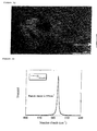
- Figure 2a shows the RAMAN spectrum of crystallized micrometric silicon.
- Figure 2b shows the RAMAN spectrum of crystallized nanoscale silicon.
- Figure 2c shows the RAMAN spectrum of amorphous nanometric silicon.
- FIG. 3 shows the cycling curves of a half-battery comprising an anode active material composed of a nanocomposite If 1.6 -C 6 according to the invention.
- the mass percentage of carbon is 62% relative to the weight of the composite.
- the discharge is carried out at C / 20.
- FIG. 4 represents the cycling curves of a half-accumulator comprising an anodic active material consisting of a Si 1.6 -C 6 nanocomposite according to the invention.
- the mass percentage of carbon is 62% relative to the weight of the composite.
- the discharge is carried out at C / 10.
- Figure 5 shows the capacity variation of a half-accumulator during a C / 10 and C / 20 cycling.
- FIG. 6 represents the cycling curves of an accumulator comprising an anodic active material according to the invention and a cathode based on LiCoO 2 .
- the discharge is carried out at a current of C / 2 at 25 ° C.
- FIG. 7 represents the cycling curves of an accumulator comprising an anodic active material according to the invention and a cathode based on LiCoO 2 .
- the discharge is carried out at a current of C / 5 at 25 ° C.
- the nanoscale silicon powder is manufactured by the plasma-assisted chemical vapor deposition (PECVD) or CO 2 laser technique.
- PECVD plasma enhanced chemical vapor deposition
- SiH 4 silane
- the plasma enhanced chemical vapor deposition (PECVD) technique consists in introducing into a chamber a silicon-based gas, generally SiH 4 (silane), at a very low pressure, of the order of 1 ⁇ bar at 1 mbar, then to decompose this gas.
- SiH 4 silane
- the silicon resulting from the decomposition of the gas is deposited in a thin layer on a substrate and a large part of the hydrogen is removed.
- the decomposition of the gas into plasma is obtained under the effect of an excitation such as a continuous electric discharge, a radio-frequency discharge, a very high frequency discharge, or microwaves. Other modes of excitation can also be envisaged.
- the silane may also be introduced into the chamber in a mixture with at least one other gas chosen from hydrogen, helium or argon
- This technique makes it possible, by modifying the synthesis parameters, such as the temperature of the substrate, the geometry of the reactor, the pressure, the power of the excitation, the deposition rate, the degree of dilution of the silane, to obtain particles. of silicon having different states of crystallization, morphology and size.
- the silicon obtained is amorphous.
- the anode of a lithium-ion battery comprising amorphous silicon particles has better performance than a lithium-ion battery anode comprising polymorphic or crystallized silicon particles.
- the synthesis method of the invention makes it possible to obtain silicon particles smaller than 100 nm in size.
- Other synthetic methods such as mechanosynthesis, for example by grinding silicon in a ball mill, do not make it possible to obtain particles as small as with the method of the invention.
- the size of the silicon particles does not exceed 50 nm. More preferably, the size of the silicon particles does not exceed 30 nm. More preferably, the size of the silicon particles does not exceed 5 nm.
- FIGS. 1a, 1b and 1c show photographs by transmission electron microscopy of silicon particles synthesized according to the invention. These figures show that the size of the silicon particles is less than 100 nm.
- FIGS. 1d, 1e and 1f show the images obtained by high resolution transmission electron microscopy of samples of amorphous, polymorphic and crystalline silicon, respectively.
- Figure 1f corresponding to crystalline silicon, shows well-defined concentric rings.
- Figure 1d corresponding to amorphous silicon has concentric rings of larger diameter and whose limit is poorly defined.
- RAMAN spectroscopy is complementary to transmission electron microscopy because it makes it possible to determine the order of magnitude of the particle size of an entire silicon sample and its crystallization state, whereas electron microscopy only provides these characteristics for the portion of the sample bombarded by the electrons.
- the RAMAN spectrum of silicon comprises a band whose position and shape are functions of the size and the crystalline state of the silicon particles.
- Figure 2a shows the RAMAN spectrum of micrometric crystalline silicon. This spectrum has a narrow band at the frequency of 520 cm -1 , whose width at half height is about 7 cm -1 .
- Figure 2b shows the RAMAN spectrum of nanoscale crystalline silicon. This spectrum has a band at the frequency of 500 cm -1 , whose width at half height is about 22 cm -1 .
- the spectrum band of Figure 2a moves to a lower frequency and broadens asymmetrically as the size of the silicon particles changes from the micrometer to the nanometer range.
- Figure 2c shows the RAMAN spectrum of amorphous nanometric silicon. This spectrum has a band at the frequency of 469 cm -1 whose width at half height is about 100 cm -1 .
- the spectrum band of Figure 2b moves to a lower frequency and broadens asymmetrically as the crystalline silicon becomes amorphous. RAMAN spectroscopy thus makes it possible to differentiate crystalline micron silicon from amorphous nanometric silicon.
- the specific surface of the synthesized nanoscale silicon powder is from 5 m 2 / g to 180 m 2 / g, which is up to 30 times higher than micron silicon powders.
- the specific surface area is from 5 m 2 / g to 80 m 2 / g.
- step b) of the process the nanoscale silicon powder is mixed with a carbon-based polymer, and a solvent is optionally added to the mixture in order to dissolve the carbon polymer.
- the dissolution of the carbonaceous polymer makes it possible to obtain good dispersion of the nanoscale silicon particles in the carbonaceous polymer and, after the subsequent pyrolysis step of the mixture, good dispersion of the silicon particles in a carbon matrix.
- the solvent may be chosen from the group comprising, for example, propylene oxide, acetone or their mixture. The mixture thus produced is kept under mechanical stirring at room temperature until the solvent is evaporated.
- the carbonaceous polymer is polyvinyl chloride (PVC) and the organic solvent is propylene oxide.
- the nanoscale silicon powder is mixed with PVC, propylene oxide and up to 20% graphite. This embodiment allows better mechanical strength of the composite during the anode manufacturing step and better conductivity.
- the nanoscale silicon powder is mixed with PVC, propylene oxide and carbon fibers.
- the amount of polymer is chosen so that the mass percentage of carbon in the final nanocomposite is 45 to 75%.
- the mass percentage of carbon in the final nanocomposite is 50 to 70%. More preferably, the mass percentage of carbon in the final nanocomposite is 50 to 65%.
- the mass percentage of carbon in the final nanocomposite is less than 45%, the mechanical strength of the electrode is insufficient.
- the mass percentage of carbon in the final nanocomposite is greater than 75%, the mass capacity of the electrode obtained is insufficient.
- step c) of the process the pyrolysis of the mixture is carried out by firing at a temperature of between 750 ° C. and 1000 ° C. under an inert atmosphere, for 1 to 8 hours, advantageously for about 4 hours.
- a pyrolysis temperature of 900 ° C. is preferred.
- the size of the silicon particles, embedded in the carbon resulting from the pyrolysis of the carbonaceous polymer, is not modified during the pyrolysis, as shown in FIG. 1 g. Indeed, the silicon particles keep a size less than 100 nm.
- the pyrolysis temperature range is preferably limited to 1000 ° C. in order to prevent the formation of silicon carbide SiC, which is harmful to electrochemical cycling.
- the presence of silicon carbide on a Si-C nanocomposite obtained according to the invention at 1000 ° C. is not detected by X-ray diffraction. This means that in the case where silicon carbide is present, it is either amorphous or too small to be detected.
- the presence of silicon carbide is also not revealed by RAMAN spectroscopy.
- the silicon contained in the nanocomposite recrystallizes. After pyrolysis, the silicon particles that were in an amorphous state evolve to a polymorphic state; those in a polymorphic state evolve to a crystallized state.
- the recrystallization of the silicon during the pyrolysis is incomplete and the silicon in the nanocomposite is polymorphic.
- the Applicant believes that the first electrochemical insertion of lithium into the crystalline structure of silicon is accompanied by a variation in the volume of the crystal lattice. This variation is reduced when the silicon is only partially crystallized or preferably when it is amorphous. It will therefore be preferable to obtain a silicon powder and an Si-C nanocomposite in a state of least advanced crystallization, so as to minimize the variations in the volume of silicon during the insertion of lithium into the silicon structure.
- the step of mixing the silicon nanoparticles in a solution of a carbon polymer followed by the pyrolysis of this mixture makes it possible to obtain good dispersion of the silicon nanoparticles in the carbonaceous mass. Mechanosynthesis does not allow to obtain such a good dispersion. High resolution scanning electron microscopy makes it possible to judge the quality of the dispersion.
- the Si-C nanocomposite thus prepared serves as the anodic active material of a lithium battery.
- the anode comprises Si-C nanocomposite, carbon black and a binder.
- Carbon black serves to improve the electrical conduction of the electrode; it represents approximately 2% to 25% of the weight of the anodic active ingredient.
- the binder may be soluble in an aqueous medium and contain for example a mixture of carboxymethylcellulose (CMC) polymer and a butadiene-styrene copolymer (SBR), in a total proportion ranging from 2 to 20% by weight of the active ingredient. anodic.
- CMC carboxymethylcellulose
- SBR butadiene-styrene copolymer
- the binder may also be soluble in an organic medium and contain for example polyvinylidene fluoride (PVDF) in a proportion ranging from 2 to 20% by weight of the anodic active material.
- PVDF polyvinylidene fluoride
- the second and third groups also include materials adapted to operate at voltages greater than 4.5 V with respect to Li + / Li such as, for example, those described in the patent application. FR2831993 .
- the electrolyte used is a conventional electrolyte in the art of lithium batteries.
- the solvent is a mixture of organic solvents chosen from linear carbonates, saturated cyclic carbonates, unsaturated cyclic carbonates and linear esters.
- the solvents may be selected from the group consisting of ethylene carbonate (EC), propylene carbonate (PC), dimethyl carbonate (DMC) and vinylidene carbonate (VC).
- a lithium salt is dissolved in this mixture of solvents. It may be chosen from the group comprising lithium hexafluorophosphate (LiPF 6 ), lithium tetrafluoroborate (LiBF 4 ), lithium hexafluoroarsenate (LiAsF 6 ), lithium perchlorate (LiClO 4 ), lithium bis oxalatoborate (LiBOB), lithium trifluoromethanesulfonimide LiN (CF 3 SO 2 ) 2 (LiTFSI), lithium bisperfluoroethylsulfonylimide (LiBETI), lithium trifluoromethanesulfonemethide LiC (CF 3 SO 2 ) 3 (LiTFSM).
- LiPF 6 lithium hexafluorophosphate
- LiBF 4 lithium tetrafluoroborate
- LiAsF 6 lithium hexafluoroarsenate
- LiClO 4 lithium perchlorate
- LiBOB lithium bis
- the concentration of this salt in the solvent mixture is variable, for example between 0.5 and 1.5 times molar in the solvent, preferably once molar.
- the invention is not limited to lithium-ion accumulators; it also applies to lithium-polymer accumulators.
- Nanoamorphous silicon is prepared under the following conditions. A mixture of silane and argon is introduced under a pressure of 6.6 ⁇ 10 -4 bar into the reaction chamber. The temperature of the substrate is about 250 ° C. The power a radio-frequency discharge is about 10 to 20 W. The silicon powder collected on the substrate is then mixed with a sufficient amount of PVC to obtain a nanocomposite -C 6 If 1.6 containing 62% by weight of carbon . The mixture is heated to 900 ° C. The nanocomposite thus obtained is used in the manufacture of an anode. This anode is assembled with a counter-electrode and a lithium metal reference electrode so as to form a half-accumulator.
- the half-battery is tested during charge-discharge cycles at 25 ° C.
- the discharge current is C / 20 and C / 10, where C is the charging rate of the battery in one hour.
- Figures 3 and 4 show the results of the cycling tests for discharge at C / 20 and C / 10, respectively. Discharged capacity is measured using a coulometer.
- Figures 3 and 4 indicate that the discharged capacity is between 1200 and 1400 mAh / g.
- FIG. 5 indicates a stable capacity of the half-accumulator during cycling, which proves that the nanocomposite of the invention is mechanically stable.
- the insertion of lithium into the silicon particles embedded in the carbon mass is reversible, with a small volume variation of the Li x Si alloy.
- the presence of the carbon matrix around the silicon particles maintains the electrical contact and ensures the cohesion of the material.
- the duration of cycling, corresponding to a loss of capacity of 10%, is at least one hundred cycles.
- the mechanical stability of the nanocomposite can be increased by increasing the amount of carbon in the nanocomposite.
- the battery is tested during charge-discharge cycles at 25 ° C.
- Figures 6 and 7 show the results of the cycling tests for discharge at currents of C / 2 and C / 5, respectively. It is found that the discharged capacity is greater than 1000 mAh / g.
- the accumulator comprising an anode according to the invention therefore has an increase in capacitance with respect to the lithium-ion accumulators comprising an anode material of the prior art.
- Table 1 compares the mass capacities and the mass and volume energies of the anode material of the accumulator according to the invention. with those of anode materials known from the prior art. For simplicity, these comparative calculations were performed considering a simple stack stack 0.5 mm thick, an anode, a separator and a cathode. A direct evaluation of the energy gain is thus obtained by replacing the carbon anode with an anode comprising the Si-C nanocomposite according to the invention. Such a calculation does not take into account the mechanical design of the accumulator.
- the Si-C nanocomposite according to the invention makes it possible to obtain a mass capacity four times greater than that of a carbon anode. It also makes it possible to increase the mass and / or volume energies by 20% and 30% respectively with respect to the use of a conventional carbon anode.
- the nanocomposite according to the invention also has the advantage of providing a high electrochemical efficiency of about 90% in the first cycle.
- the electrochemical efficiency being defined as the ratio between the quantity of electricity discharged by the accumulator and the quantity of electricity charged to the accumulator before this discharge.
Abstract
Description
L'invention a pour objet un matériau nanocomposite de silicium-carbone pour anode d'accumulateur au lithium. Ce matériau présente une capacité et une stabilité en cyclage élevées par rapport aux matériaux d'anode connus dans l'état de l'art des accumulateurs au lithium. L'invention a également pour objet un procédé de fabrication du matériau nanocomposite et un accumulateur dont l'anode comprend ce matériau nanocomposite.The subject of the invention is a silicon-carbon nanocomposite material for lithium battery anode. This material has a high capacity and a high cycling stability compared to the anode materials known in the state of the art of lithium batteries. The subject of the invention is also a process for manufacturing the nanocomposite material and an accumulator whose anode comprises this nanocomposite material.
L'évolution des applications électroniques portables nécessite l'utilisation d'accumulateurs offrant une capacité énergétique de plus en plus élevée.The evolution of portable electronic applications requires the use of accumulators with an increasing energy capacity.
L'accumulateur lithium-ion actuel, comprenant une anode à base de carbone et une cathode à base de LiNiO2 dopé, de LiCoO2, de LiMnO2 ou de LiMn2O4 dopé, possède des énergies massique et volumique limitées. Les énergies massique et volumique des accumulateurs Li-ion actuellement disponibles sur le marché évoluent entre 160 et 200 Wh/kg et entre 430 et 500 Wh/l respectivement, en fonction des technologies d'électrodes et de boîtiers.The current lithium-ion battery comprising a carbon-based anode and a cathode based on doped LiNiO 2, LiCoO 2, LiMnO of 2 or LiMn 2 O 4 doped, has mass energy and volume limited. The mass and volume energies of Li-ion accumulators currently available on the market vary between 160 and 200 Wh / kg and between 430 and 500 Wh / l respectively, depending on the technologies of electrodes and housings.
L'énergie délivrée par un accumulateur au lithium est en outre limitée par l'anode à base de carbone, qui a certes une longue durée de vie, mais une capacité réversible limitée à environ 300-350 mAh/g. (La capacité réversible est définie comme étant la quantité d'électricité générée au cours de la décharge par la désinsertion réversible des atomes de lithium hors du carbone).The energy delivered by a lithium battery is further limited by the carbon-based anode, which certainly has a long life, but a reversible capacity limited to about 300-350 mAh / g. (The reversible capacity is defined as the amount of electricity generated during the discharge by the reversible deinsertion of the lithium atoms out of the carbon).
Pour répondre à ces besoins énergétiques croissants, des recherches sont menées sur de nouveaux matériaux d'anode présentant une capacité supérieure à celle du carbone. Les composés intermétalliques, le silicium pur et l'étain pur en font partie. Ceux-ci présentent une capacité massique théorique élevée (de 500 à 4000 mAh/g), mais une tenue en cyclage mauvaise voire catastrophique, notamment en raison de très fortes variations volumiques provoquées par les cycles d'insertion/ désinsertion du lithium dans ces composés. Le silicium comme matériau anodique possède une capacité massique très élevée, allant de 2000 à 4000 mAh/g, mais ne présente pas une bonne stabilité en cyclage. L'homme du métier est donc réduit à utiliser soit du carbone, présentant une capacité massique faible, soit de nouveaux matériaux insuffisamment stables en cyclage.To meet these growing energy needs, research is being conducted on new anode materials with a higher capacity than carbon. Intermetallic compounds, pure silicon and pure tin are among them. These have a high theoretical mass capacity (from 500 to 4000 mAh / g), but a bad or even catastrophic cycling performance, in particular because of very large volume variations caused by the cycles of insertion / deinsertion of lithium in these compounds. . Silicon as anode material has a very high mass capacity, ranging from 2000 to 4000 mAh / g, but does not have a good stability in cycling. Those skilled in the art are therefore reduced to using either carbon, having a low mass capacity, or new materials insufficiently stable in cycling.
L'étude de l'art antérieur indique que plusieurs travaux se sont orientés vers la recherche de composites Si-C stables ou pseudo-stables en cyclage et présentant des capacités massiques de 500 à 900 mAh/g. Un composite est défini comme un matériau formé de plusieurs constituants, dont une matière plastique, pour obtenir des propriétés mécaniques particulières.The study of the prior art indicates that several studies have turned towards the search for Si-C composites which are stable or pseudo-stable in cycling and which have mass capacities of 500 to 900 mAh / g. A composite is defined as a material formed of several constituents, including a plastic material, to obtain particular mechanical properties.
Le document
Le document
Le document
Les procédés décrits dans ces 3 derniers documents permettent d'obtenir un composite avec des particules nanométriques de silicium. Cependant la synthèse du composite s'accompagne de la formation de carbure de silicium SiC, néfaste aux performances électrochimiques et les performances électrochimiques des composites Si-C ainsi synthétisés sont insuffisantes par rapport aux objectifs de capacités recherchés.The processes described in these last 3 documents make it possible to obtain a composite with nanometric silicon particles. However, the synthesis of the composite is accompanied by the formation of silicon carbide SiC, harmful to the electrochemical performance and electrochemical performance Si-C composites thus synthesized are insufficient compared to the objectives of desired capabilities.
Les documents
Le document
L'abrégé de la publication n°5 du congrès IMLB-Nara-Japon de juin 2004 décrit un matériau composite Si-C comprenant des particules de silicium dont la taille est comprise entre 100 nm et 1 µm. Le choix de cette plage de tailles permet de minimiser les variations de volume des particules de silicium dans des conditions de cyclage. La Figure 1 donne une indication de la capacité massique de ce matériau composite au cours d'un cyclage d'une dizaine de cycles. Celle-ci est inférieure à 1000 mAh/g.The abstract of publication No. 5 of the IMLB-Nara-Japan congress of June 2004 describes an Si-C composite material comprising silicon particles whose size is between 100 nm and 1 μm. The choice of this size range makes it possible to minimize the volume variations of the silicon particles under cycling conditions. Figure 1 gives an indication of the mass capacity of this composite material during a cycle of ten cycles. This is less than 1000 mAh / g.
L'abrégé de la publication n°78 du congrès IMLB-Nara-Japon de juin 2004 décrit un matériau nanocomposite Si-C préparé par moulin à billes (ball mill). La capacité massique de ce matériau mesurée au cours du premier cycle est d'environ 1020 mAh/g. Elle chute rapidement car elle n'est plus que d'environ 680 mAh/g au deuxième cycle.The abstract of publication No. 78 of the IMLB-Nara-Japan congress of June 2004 describes a nanocomposite material Si-C prepared by ball mill. The mass capacity of this material measured during the first cycle is about 1020 mAh / g. It drops rapidly because it is only about 680 mAh / g at the second cycle.
L'abrégé de la publication n°79 du congrès IMLB-Nara-Japon de juin 2004 décrit un nanocomposite Si-C obtenu par pyrolyse d'un mélange de polychlorure de vinyle et d'une poudre composite de graphite et de silicium au préalablement broyée par un moulin à billes. Le procédé de broyage par moulin à billes ne permet pas d'obtenir une capacité supérieure à 1000 mAh/g.The abstract of publication 79 of the IMLB-Nara-Japan congress of June 2004 describes a Si-C nanocomposite obtained by pyrolysis of a mixture of polyvinyl chloride and a graphite and silicon composite powder which had been ground beforehand. by a ball mill. The ball mill grinding process does not make it possible to obtain a capacity greater than 1000 mAh / g.
L'abrégé de la publication n°83 du congrès IMLB-Nara-Japon de juin 2004 décrit le dépôt de carbone à la surface de particules de silicium par une méthode de dépôt de couche par précipitation de vapeurs métalliques ou par pyrolyse d'un mélange de polychlorure de vinyle, de graphite et de silicium. La capacité réversible obtenue est de 1000 mAh/g, ce qui est insuffisant.The Abstract of Publication No. 83 of the IMLB-Nara-Japan Congress of June 2004 describes the deposition of carbon on the surface of silicon particles by a layer deposition method by precipitation of metal vapors or by pyrolysis of a mixture polyvinyl chloride, graphite and silicon. The reversible capacity obtained is 1000 mAh / g, which is insufficient.
On recherche donc un matériau anodique de type composite silicium-carbone pour accumulateur au lithium, présentant une capacité massique réversible nettement plus élevée que celle du carbone et des autres matériaux anodiques alternatifs (Si-C micrométrique, composés intermétalliques, phosphures) et une bonne stabilité en cyclage.An anode material of the silicon-carbon composite type for lithium accumulator is therefore sought, having a reversible mass capacity that is significantly higher than that of carbon and other alternative anode materials (micrometric Si-C, intermetallic compounds, phosphides) and good stability. in cycling.
A cet effet, l'invention propose un matériau anodique de type composite silicium-carbone, pour accumulateur au lithium, obtenu par un procédé de préparation novateur. Ce procédé permet de fabriquer un matériau composite de silicium-carbone comprenant des particules de silicium dont la taille est inférieure à 100 nm, et que l'on désignera par la suite par le terme de particules nanométriques.For this purpose, the invention proposes an anode material of silicon-carbon composite type, for lithium accumulator, obtained by a novel preparation process. This method makes it possible to manufacture a silicon-carbon composite material comprising silicon particles whose size is less than 100 nm, and which will be referred to as nano-sized particles.
Ce procédé de fabrication comprend les étapes consistant à :
- a) fournir une poudre de silicium obtenue par la technique de dépôt chimique en phase vapeur assisté par plasma (PECVD), ou par laser CO2, la taille des particules de silicium étant inférieure à 100 nm ;
- b) mélanger la poudre de silicium à un polymère carboné ; et
- c) effectuer la pyrolyse du mélange.
- a) providing a silicon powder obtained by the plasma-assisted chemical vapor deposition technique (PECVD), or by CO 2 laser, the size of the silicon particles being less than 100 nm;
- b) mixing the silicon powder with a carbonaceous polymer; and
- c) Pyrolysis of the mixture.
L'invention propose également un accumulateur au lithium comprenant au moins une anode dont la matière active comprend un matériau nanocomposite produit par le procédé de l'invention.The invention also proposes a lithium accumulator comprising at least one anode whose active material comprises a nanocomposite material produced by the method of the invention.
Les capacités massiques mesurées au cours de la décharge d'un tel accumulateur sont en général d'au moins 1200 mAh/g, à 25°C pour une décharge à un courant inférieur ou égal à C, et sont stables dans des conditions de cyclage de l'accumulateur.The mass capacities measured during the discharge of such an accumulator are generally at least 1200 mAh / g, at 25 ° C for a discharge at a current less than or equal to C, and are stable under cycling conditions of the accumulator.
Les figures 1 a, 1b et 1c représentent une photographie par microscopie électronique à transmission haute résolution d'une poudre de silicium nanométrique obtenue par le procédé de l'invention à différents grossissements.FIGS. 1a, 1b and 1c show a photograph by high resolution transmission electron microscopy of a nanoscale silicon powder obtained by the method of the invention at different magnifications.
Les figures 1d, 1e et 1f représentent les clichés de microscopie électronique à transmission haute résolution correspondant respectivement à des échantillons de silicium nanométrique, amorphe, polymorphe et cristallisé.FIGS. 1d, 1e and 1f represent high resolution transmission electron microscopy images respectively corresponding to samples of nanometric silicon, amorphous, polymorphic and crystallized.
La figure 1 g représente une photographie par microscopie électronique à transmission d'un nanocomposite Si-C obtenu par le procédé de l'invention.FIG. 1 g shows a transmission electron microscopy photograph of an Si-C nanocomposite obtained by the process of the invention.
La figure 2a) représente le spectre RAMAN de silicium micrométrique cristallisé.Figure 2a) shows the RAMAN spectrum of crystallized micrometric silicon.
La figure 2b) représente le spectre RAMAN de silicium nanométrique cristallisé.Figure 2b) shows the RAMAN spectrum of crystallized nanoscale silicon.
La figure 2c) représente le spectre RAMAN de silicium nanométrique amorphe.Figure 2c) shows the RAMAN spectrum of amorphous nanometric silicon.
La figure 3 représente les courbes de cyclage d'un demi-accumulateur comprenant une matière active anodique constituée d'un nanocomposite Si1,6-C6 selon l'invention. Le pourcentage massique de carbone est de 62 % par rapport au poids du composite. La décharge est réalisée au courant de C/20.3 shows the cycling curves of a half-battery comprising an anode active material composed of a nanocomposite If 1.6 -C 6 according to the invention. The mass percentage of carbon is 62% relative to the weight of the composite. The discharge is carried out at C / 20.
La figure 4 représente les courbes de cyclage d'un demi-accumulateur comprenant une matière active anodique constituée d'un nanocomposite Si1,6-C6 selon l'invention. Le pourcentage massique de carbone est de 62 % par rapport au poids du composite. La décharge est réalisée au courant de C/10.FIG. 4 represents the cycling curves of a half-accumulator comprising an anodic active material consisting of a Si 1.6 -C 6 nanocomposite according to the invention. The mass percentage of carbon is 62% relative to the weight of the composite. The discharge is carried out at C / 10.
La figure 5 représente la variation de capacité d'un demi-accumulateur au cours d'un cyclage en C/10 et C/20.Figure 5 shows the capacity variation of a half-accumulator during a C / 10 and C / 20 cycling.
La figure 6 représente les courbes de cyclage d'un accumulateur comprenant une matière active anodique selon l'invention et une cathode à base de LiCoO2. La décharge est réalisée au courant de C/2 à 25°C.FIG. 6 represents the cycling curves of an accumulator comprising an anodic active material according to the invention and a cathode based on LiCoO 2 . The discharge is carried out at a current of C / 2 at 25 ° C.
La figure 7 représente les courbes de cyclage d'un accumulateur comprenant une matière active anodique selon l'invention et une cathode à base de LiCoO2. La décharge est réalisée au courant de C/5 à 25°C.FIG. 7 represents the cycling curves of an accumulator comprising an anodic active material according to the invention and a cathode based on LiCoO 2 . The discharge is carried out at a current of C / 5 at 25 ° C.
Le procédé de préparation du nanocomposite Si-C et la structure du nanocomposite Si-C vont maintenant être décrits en détail.The process for preparing the Si-C nanocomposite and the structure of the Si-C nanocomposite will now be described in detail.
Le procédé de préparation du nanocomposite Si-C comprend :
- a) la fabrication d'une poudre de silicium nanométrique,
- b) le mélange de cette poudre avec un polymère carboné et
- c) la pyrolyse du mélange.
- a) the manufacture of a nanoscale silicon powder,
- b) the mixture of this powder with a carbon polymer and
- c) pyrolysis of the mixture.
Dans l'étape a), on fabrique la poudre de silicium nanométrique par la technique de dépôt chimique en phase vapeur assisté par plasma (PECVD) ou par laser CO2. La technique de dépôt chimique en phase vapeur assisté par plasma (PECVD) consiste à introduire dans une enceinte un gaz à base de silicium, généralement SiH4 (silane), sous très faible pression, de l'ordre de 1 µbar à 1 mbar, puis à décomposer ce gaz. Le silicium issu de la décomposition du gaz se dépose en couche mince sur un substrat et une grande partie de l'hydrogène est éliminée. La décomposition du gaz en plasma est obtenue sous l'effet d'une excitation telle qu'une décharge électrique continue, une décharge radio-fréquence, une décharge à très haute fréquence, ou des micro-ondes. D'autres modes d'excitation peuvent aussi être envisagés. Le silane peut aussi être introduit dans l'enceinte en mélange avec au moins un autre gaz choisi parmi l'hydrogène, l'hélium ou l'argon.In step a), the nanoscale silicon powder is manufactured by the plasma-assisted chemical vapor deposition (PECVD) or CO 2 laser technique. The plasma enhanced chemical vapor deposition (PECVD) technique consists in introducing into a chamber a silicon-based gas, generally SiH 4 (silane), at a very low pressure, of the order of 1 μbar at 1 mbar, then to decompose this gas. The silicon resulting from the decomposition of the gas is deposited in a thin layer on a substrate and a large part of the hydrogen is removed. The decomposition of the gas into plasma is obtained under the effect of an excitation such as a continuous electric discharge, a radio-frequency discharge, a very high frequency discharge, or microwaves. Other modes of excitation can also be envisaged. The silane may also be introduced into the chamber in a mixture with at least one other gas chosen from hydrogen, helium or argon.
Cette technique permet, en modifiant les paramètres de synthèse, tels que la température du substrat, la géométrie du réacteur, la pression, la puissance de l'excitation, la vitesse de dépôt, le degré de dilution du silane, d'obtenir des particules de silicium présentant différents états de cristallisation, de morphologie et de taille.This technique makes it possible, by modifying the synthesis parameters, such as the temperature of the substrate, the geometry of the reactor, the pressure, the power of the excitation, the deposition rate, the degree of dilution of the silane, to obtain particles. of silicon having different states of crystallization, morphology and size.
On distingue trois états de cristallisation du silicium nanométrique:
- un état totalement amorphe,
- un état polymorphe dans lequel des particules de silicium cristallisées sont noyées dans une matrice de silicium amorphe, ou encore dans lequel des particules de silicium amorphe sont mélangées à des particules cristallisées. L'état polymorphe peut être obtenu lorsqu'on effectue un recuit contrôlé de silicium amorphe.
- un état cristallisé.
- a totally amorphous state,
- a polymorphic state in which crystallized silicon particles are embedded in an amorphous silicon matrix, or in which amorphous silicon particles are mixed with crystallized particles. The polymorphic state can be obtained when performing a controlled annealing of amorphous silicon.
- a crystallized state.
De préférence, le silicium obtenu est amorphe.Preferably, the silicon obtained is amorphous.
L'anode d'un accumulateur lithium-ion comprenant des particules amorphes de silicium présente de meilleures performances qu'une anode d'accumulateur lithium-ion comprenant des particules de silicium polymorphes ou cristallisées.The anode of a lithium-ion battery comprising amorphous silicon particles has better performance than a lithium-ion battery anode comprising polymorphic or crystallized silicon particles.
La méthode de synthèse de l'invention permet d'obtenir des particules de silicium de taille inférieure à 100 nm. D'autres méthodes de synthèse telles que la mécanosynthèse par exemple par broyage de silicium dans un moulin à billes, ne permettent pas d'obtenir des particules aussi petites qu'avec le procédé de l'invention. De préférence, la taille des particules de silicium n'excède pas 50 nm. De préférence encore, la taille des particules de silicium n'excède pas 30 nm. De préférence encore, la taille des particules de silicium n'excède pas 5 nm.The synthesis method of the invention makes it possible to obtain silicon particles smaller than 100 nm in size. Other synthetic methods such as mechanosynthesis, for example by grinding silicon in a ball mill, do not make it possible to obtain particles as small as with the method of the invention. Preferably, the size of the silicon particles does not exceed 50 nm. More preferably, the size of the silicon particles does not exceed 30 nm. More preferably, the size of the silicon particles does not exceed 5 nm.
La microscopie électronique en transmission à haute résolution (METHR) permet de mesurer la taille des particules de silicium. Les figures 1a, 1b et 1c représentent des clichés par microscopie électronique en transmission de particules de silicium synthétisées selon l'invention. Ces figures montrent que la taille des particules de silicium est inférieure à 100 nm.High resolution transmission electron microscopy (METHR) is used to measure the size of silicon particles. FIGS. 1a, 1b and 1c show photographs by transmission electron microscopy of silicon particles synthesized according to the invention. These figures show that the size of the silicon particles is less than 100 nm.
Cette technique permet également de connaître l'état de cristallisation du silicium nanométrique. Les figures 1d, 1e et 1f représentent les clichés réalisés par microscopie électronique en transmission à haute résolution d'échantillons de silicium amorphe, polymorphe et cristallin respectivement.This technique also makes it possible to know the state of crystallization of nanoscale silicon. FIGS. 1d, 1e and 1f show the images obtained by high resolution transmission electron microscopy of samples of amorphous, polymorphic and crystalline silicon, respectively.
La Figure 1f correspondant au silicium cristallin, montre des anneaux concentriques bien définis. La Figure 1d correspondant au silicium amorphe présente des anneaux concentriques de plus grand diamètre et dont la limite est mal définie.Figure 1f corresponding to crystalline silicon, shows well-defined concentric rings. Figure 1d corresponding to amorphous silicon has concentric rings of larger diameter and whose limit is poorly defined.
La spectroscopie RAMAN est complémentaire à la microscopie électronique en transmission car elle permet de déterminer l'ordre de grandeur de la taille des particules d'un échantillon entier de silicium ainsi que son état de cristallisation alors que la microscopie électronique ne fournit ces caractéristiques que pour la portion de l'échantillon bombardée par les électrons.RAMAN spectroscopy is complementary to transmission electron microscopy because it makes it possible to determine the order of magnitude of the particle size of an entire silicon sample and its crystallization state, whereas electron microscopy only provides these characteristics for the portion of the sample bombarded by the electrons.
Le spectre RAMAN du silicium comprend une bande dont la position et la forme sont fonctions de la taille et de l'état cristallin des particules de silicium.The RAMAN spectrum of silicon comprises a band whose position and shape are functions of the size and the crystalline state of the silicon particles.
La figure 2a représente le spectre RAMAN de silicium cristallin micrométrique. Ce spectre présente une bande étroite à la fréquence de 520 cm-1, dont la largeur à mi-hauteur est d'environ 7 cm-1.Figure 2a shows the RAMAN spectrum of micrometric crystalline silicon. This spectrum has a narrow band at the frequency of 520 cm -1 , whose width at half height is about 7 cm -1 .
La figure 2b représente le spectre RAMAN de silicium cristallin nanométrique. Ce spectre présente une bande à la fréquence de 500 cm-1, dont la largeur à mi-hauteur est d'environ 22 cm-1. La bande du spectre de la figure 2a se déplace vers une fréquence inférieure et s'élargit de manière asymétrique lorsque la taille des particules de silicium passe du domaine micrométrique au domaine nanométrique.Figure 2b shows the RAMAN spectrum of nanoscale crystalline silicon. This spectrum has a band at the frequency of 500 cm -1 , whose width at half height is about 22 cm -1 . The spectrum band of Figure 2a moves to a lower frequency and broadens asymmetrically as the size of the silicon particles changes from the micrometer to the nanometer range.
La Figure 2c représente le spectre RAMAN de silicium nanométrique amorphe. Ce spectre présente une bande à la fréquence de 469 cm-1 dont la largeur à mi-hauteur est d'environ 100 cm-1. La bande du spectre de la figure 2b se déplace vers une fréquence inférieure et s'élargit de manière asymétrique lorsque le silicium cristallin devient amorphe. La spectroscopie RAMAN permet donc de différencier le silicium micrométrique cristallin du silicium nanométrique amorphe.Figure 2c shows the RAMAN spectrum of amorphous nanometric silicon. This spectrum has a band at the frequency of 469 cm -1 whose width at half height is about 100 cm -1 . The spectrum band of Figure 2b moves to a lower frequency and broadens asymmetrically as the crystalline silicon becomes amorphous. RAMAN spectroscopy thus makes it possible to differentiate crystalline micron silicon from amorphous nanometric silicon.
La surface spécifique de la poudre de silicium nanométrique synthétisée est de 5 m2/g à 180 m2/g, ce qui est jusqu'à 30 fois supérieur aux poudres de silicium micrométriques. De préférence, la surface spécifique est de 5 m2/g à 80 m2/g.The specific surface of the synthesized nanoscale silicon powder is from 5 m 2 / g to 180 m 2 / g, which is up to 30 times higher than micron silicon powders. Preferably, the specific surface area is from 5 m 2 / g to 80 m 2 / g.
Dans l'étape b) du procédé, la poudre nanométrique de silicium est mélangée à un polymère carboné, et un solvant est éventuellement ajouté au mélange afin de dissoudre le polymère carboné. La dissolution du polymère carboné, permet d'obtenir une bonne dispersion des particules de silicium nanométriques dans le polymère carboné et, après l'étape suivante de pyrolyse du mélange, une bonne dispersion des particules de silicium dans une matrice carbonée. Le solvant peut être choisi dans le groupe comprenant par exemple l'oxyde de propylène, l'acétone ou leur mélange. Le mélange ainsi réalisé est maintenu sous agitation mécanique à température ambiante jusqu'à évaporation du solvant.In step b) of the process, the nanoscale silicon powder is mixed with a carbon-based polymer, and a solvent is optionally added to the mixture in order to dissolve the carbon polymer. The dissolution of the carbonaceous polymer makes it possible to obtain good dispersion of the nanoscale silicon particles in the carbonaceous polymer and, after the subsequent pyrolysis step of the mixture, good dispersion of the silicon particles in a carbon matrix. The solvent may be chosen from the group comprising, for example, propylene oxide, acetone or their mixture. The mixture thus produced is kept under mechanical stirring at room temperature until the solvent is evaporated.
Dans un mode préféré de réalisation, le polymère carboné est du polychlorure de vinyle (PVC) et le solvant organique est l'oxyde de propylène.In a preferred embodiment, the carbonaceous polymer is polyvinyl chloride (PVC) and the organic solvent is propylene oxide.
Dans un autre mode de réalisation de l'invention, la poudre nanométrique de silicium est mélangée à du PVC, à de l'oxyde de propylène et jusqu'à 20 % de graphite. Ce mode de réalisation permet une meilleure robustesse mécanique du composite pendant l'étape de fabrication de l'anode et une meilleure conductivité.In another embodiment of the invention, the nanoscale silicon powder is mixed with PVC, propylene oxide and up to 20% graphite. This embodiment allows better mechanical strength of the composite during the anode manufacturing step and better conductivity.
Dans un autre mode de réalisation de l'invention, la poudre nanométrique de silicium est mélangée à du PVC, à de l'oxyde de propylène et à des fibres de carbone..In another embodiment of the invention, the nanoscale silicon powder is mixed with PVC, propylene oxide and carbon fibers.
La quantité de polymère est choisie de manière à ce que le pourcentage massique de carbone dans le nanocomposite final soit de 45 à 75 %. De préférence, le pourcentage massique de carbone dans le nanocomposite final est de 50 à 70 %. De préférence encore, le pourcentage massique de carbone dans le nanocomposite final est de 50 à 65 %. Lorsque le pourcentage massique de carbone dans le nanocomposite final est inférieur à 45 %, la tenue mécanique de l'électrode est insuffisante. Lorsque le pourcentage massique de carbone dans le nanocomposite final est supérieur à 75 %, la capacité massique de l'électrode obtenue est insuffisante.The amount of polymer is chosen so that the mass percentage of carbon in the final nanocomposite is 45 to 75%. Preferably, the mass percentage of carbon in the final nanocomposite is 50 to 70%. More preferably, the mass percentage of carbon in the final nanocomposite is 50 to 65%. When the mass percentage of carbon in the final nanocomposite is less than 45%, the mechanical strength of the electrode is insufficient. When the mass percentage of carbon in the final nanocomposite is greater than 75%, the mass capacity of the electrode obtained is insufficient.
Dans l'étape c) du procédé, on effectue la pyrolyse du mélange par cuisson à une température comprise entre 750°C et 1000°C sous atmosphère inerte, pendant 1 à 8 heures, avantageusement environ 4 heures. Dans le cas d'un polymère de PVC, on préfèrera une température de pyrolyse de 900°C. La taille des particules de silicium, noyées dans le carbone issu de la pyrolyse du polymère carboné, n'est pas modifiée au cours de la pyrolyse, comme le montre la Figure 1 g. En effet, les particules de silicium gardent une taille inférieure à 100 nm.In step c) of the process, the pyrolysis of the mixture is carried out by firing at a temperature of between 750 ° C. and 1000 ° C. under an inert atmosphere, for 1 to 8 hours, advantageously for about 4 hours. In the case of a PVC polymer, a pyrolysis temperature of 900 ° C. is preferred. The size of the silicon particles, embedded in the carbon resulting from the pyrolysis of the carbonaceous polymer, is not modified during the pyrolysis, as shown in FIG. 1 g. Indeed, the silicon particles keep a size less than 100 nm.
La plage de température de pyrolyse est limitée de préférence à 1000°C afin d'éviter la formation de carbure de silicium SiC, néfaste au cyclage électrochimique. On ne détecte pas, par diffraction des rayons X, la présence de carbure de silicium sur un nanocomposite Si-C obtenu selon l'invention à 1000°C. Ceci signifie que dans l'hypothèse où du carbure de silicium est présent, il est soit amorphe, soit en quantité trop faible pour être détectée. La présence de carbure de silicium n'est pas non plus mise en évidence par spectroscopie RAMAN.The pyrolysis temperature range is preferably limited to 1000 ° C. in order to prevent the formation of silicon carbide SiC, which is harmful to electrochemical cycling. The presence of silicon carbide on a Si-C nanocomposite obtained according to the invention at 1000 ° C. is not detected by X-ray diffraction. This means that in the case where silicon carbide is present, it is either amorphous or too small to be detected. The presence of silicon carbide is also not revealed by RAMAN spectroscopy.
En revanche pour une température de pyrolyse de 1150°C, la présence de carbure de silicium peut être mise en évidence par diffraction des rayons X et spectroscopie de perte d'énergie des électrons (EELS).On the other hand, for a pyrolysis temperature of 1150 ° C., the presence of silicon carbide can be demonstrated by X-ray diffraction and electron energy loss spectroscopy (EELS).
Au cours de la pyrolyse, le silicium contenu dans le nanocomposite recristallise. Après pyrolyse, les particules de silicium qui étaient dans un état amorphe évoluent vers un état polymorphe ; celles qui étaient dans un état polymorphe évoluent vers un état cristallisé.During pyrolysis, the silicon contained in the nanocomposite recrystallizes. After pyrolysis, the silicon particles that were in an amorphous state evolve to a polymorphic state; those in a polymorphic state evolve to a crystallized state.
De préférence, la recristallisation du silicium au cours de la pyrolyse est incomplète et le silicium dans le nanocomposite est polymorphe. Sans vouloir être liée par une théorie, la demanderesse pense que la première insertion électrochimique de lithium dans la structure cristalline du silicium s'accompagne d'une variation de volume de la maille cristalline. Cette variation est réduite lorsque le silicium n'est que partiellement cristallisé ou de préférence lorsqu'il est amorphe. On préférera donc obtenir une poudre de silicium et un nanocomposite Si-C dans un état de cristallisation le moins avancé, de façon à minimiser les variations de volume du silicium lors de l'insertion du lithium dans la structure du silicium.Preferably, the recrystallization of the silicon during the pyrolysis is incomplete and the silicon in the nanocomposite is polymorphic. Without wishing to be bound by theory, the Applicant believes that the first electrochemical insertion of lithium into the crystalline structure of silicon is accompanied by a variation in the volume of the crystal lattice. This variation is reduced when the silicon is only partially crystallized or preferably when it is amorphous. It will therefore be preferable to obtain a silicon powder and an Si-C nanocomposite in a state of least advanced crystallization, so as to minimize the variations in the volume of silicon during the insertion of lithium into the silicon structure.
L'étape de mélange des nanoparticules de silicium dans une solution d'un polymère carboné suivie de la pyrolyse de ce mélange permet d'obtenir une bonne dispersion des nanoparticules de silicium dans la masse carbonée. La mécanosynthèse ne permet pas d'obtenir une aussi bonne dispersion. La microscopie électronique à balayage à haute résolution permet de juger de la qualité de la dispersion.The step of mixing the silicon nanoparticles in a solution of a carbon polymer followed by the pyrolysis of this mixture makes it possible to obtain good dispersion of the silicon nanoparticles in the carbonaceous mass. Mechanosynthesis does not allow to obtain such a good dispersion. High resolution scanning electron microscopy makes it possible to judge the quality of the dispersion.
Le nanocomposite Si-C ainsi préparé sert de matière active anodique d'un accumulateur au lithium.The Si-C nanocomposite thus prepared serves as the anodic active material of a lithium battery.
L'anode comprend le nanocomposite Si-C, du noir de carbone et un liant.The anode comprises Si-C nanocomposite, carbon black and a binder.
Le noir de carbone sert à améliorer la conduction électrique de l'électrode ; il représente environ de 2 % à 25 % du poids de la matière active anodique.Carbon black serves to improve the electrical conduction of the electrode; it represents approximately 2% to 25% of the weight of the anodic active ingredient.
Le liant peut être soluble en milieu aqueux et contenir par exemple un mélange de polymère de carboxyméthylcellulose (CMC) et d'un copolymère de butadiène - styrène (SBR), en une proportion totale allant de 2 à 20 % en poids de la matière active anodique. Le liant peut aussi être soluble en milieu organique et contenir par exemple du polyfluorure de vinylidène (PVDF) en une proportion allant de 2 à 20 % en poids de la matière active anodique.The binder may be soluble in an aqueous medium and contain for example a mixture of carboxymethylcellulose (CMC) polymer and a butadiene-styrene copolymer (SBR), in a total proportion ranging from 2 to 20% by weight of the active ingredient. anodic. The binder may also be soluble in an organic medium and contain for example polyvinylidene fluoride (PVDF) in a proportion ranging from 2 to 20% by weight of the anodic active material.
La matière active cathodique peut être choisie parmi l'un ou plusieurs des matériaux des trois groupes suivants :
- le premier groupe comprend LiNiO2, LiCoO2, LiMnO2. Ni, Co et Mn peuvent être substitués par l'un ou par plusieurs des éléments choisis dans le groupe comprenant Mg, Mn (sauf pour LiMnO2), AI, B, Ti, V, Si, Cr, Fe, Cu, Zn, Zr.
- le second groupe comprend les oxydes mixtes de phosphore, de lithium, et d'au moins un métal de transition de formule générale LixMzPO4 où 0 ≤ x ≤ 3 et z = 1
ou 2. Des exemples de tels oxydes sont : LiMnPO4, LiCoPO4, LiFePO4, LiVPO4F et Li3Fe2PO4. - le troisième groupe comprend LiMn2O4, Mn pouvant être substitué par l'un ou par plusieurs des éléments choisis dans le groupe comprenant Ni, Co, Mg, Al, B, Ti, V, Si, Cr, Fe, Cu, Zn, Zr.
- the first group comprises LiNiO 2 , LiCoO 2 , LiMnO 2 . Ni, Co and Mn may be substituted by one or more of the elements selected from the group consisting of Mg, Mn (except for LiMnO 2 ), Al, B, Ti, V, Si, Cr, Fe, Cu, Zn, Zr.
- the second group comprises mixed oxides of phosphorus, of lithium, and of at least one transition metal of general formula Li x M z PO 4 where 0 ≤ x ≤ 3 and z = 1 or 2. Examples of such oxides are LiMnPO 4 , LiCoPO 4 , LiFePO 4 , LiVPO 4 F and Li 3 Fe 2 PO 4 .
- the third group comprises LiMn 2 O 4 , Mn may be substituted by one or more of the elements selected from the group consisting of Ni, Co, Mg, Al, B, Ti, V, Si, Cr, Fe, Cu, Zn , Zr.
Les deuxième et troisième groupes comprennent aussi les matériaux adaptés à fonctionner à des tensions supérieures à 4,5 V par rapport à Li+/Li tels que, par exemple, ceux décrits dans la demande de brevet
L'électrolyte utilisé est un électrolyte classique dans l'art des accumulateurs au lithium. Le solvant est un mélange de solvants organiques choisis parmi les carbonates linéaires, les carbonates cycliques saturés, les carbonates cycliques insaturés, les esters linéaires. Les solvants peuvent être choisis dans le groupe comprenant le carbonate d'éthylène (EC), le carbonate de propylène (PC), le carbonate de diméthyle (DMC) et le carbonate de vinylidènè (VC).The electrolyte used is a conventional electrolyte in the art of lithium batteries. The solvent is a mixture of organic solvents chosen from linear carbonates, saturated cyclic carbonates, unsaturated cyclic carbonates and linear esters. The solvents may be selected from the group consisting of ethylene carbonate (EC), propylene carbonate (PC), dimethyl carbonate (DMC) and vinylidene carbonate (VC).
Un sel de lithium est dissous dans ce mélange de solvants. Il peut être choisi dans le groupe comprenant l'hexafluorophosphate de lithium (LiPF6), le tétrafluoroborate de lithium (LiBF4), l'hexafluoroarsénate de lithium (LiAsF6), le perchlorate de lithium (LiClO4), le lithium Bis oxalatoborate (LiBOB), le trifluorométhane sulfonimide de lithium LiN(CF3SO2)2 (LiTFSI), le lithium bisperfluoroethylsulfonylimide (LiBETI), le lithium trifluorométhanesulfoneméthide LiC(CF3SO2)3 (LiTFSM).A lithium salt is dissolved in this mixture of solvents. It may be chosen from the group comprising lithium hexafluorophosphate (LiPF 6 ), lithium tetrafluoroborate (LiBF 4 ), lithium hexafluoroarsenate (LiAsF 6 ), lithium perchlorate (LiClO 4 ), lithium bis oxalatoborate (LiBOB), lithium trifluoromethanesulfonimide LiN (CF 3 SO 2 ) 2 (LiTFSI), lithium bisperfluoroethylsulfonylimide (LiBETI), lithium trifluoromethanesulfonemethide LiC (CF 3 SO 2 ) 3 (LiTFSM).
La concentration de ce sel dans le mélange de solvants est variable, par exemple entre 0,5 et 1,5 fois molaire dans le solvant, de préférence une fois molaire. L'invention n'est pas limitée aux accumulateurs lithium-ion ; elle s'applique également aux accumulateurs lithium-polymère.The concentration of this salt in the solvent mixture is variable, for example between 0.5 and 1.5 times molar in the solvent, preferably once molar. The invention is not limited to lithium-ion accumulators; it also applies to lithium-polymer accumulators.
Des tests ont été effectués :
- 1) d'une part sur un demi-accumulateur comprenant :
- une anode comprenant un nanocomposite Si-C selon l'invention
- une contre-électrode et une électrode de référence en lithium métallique,
- 2) d'autre part sur un accumulateur comprenant :
- une anode comprenant un nanocomposite Si-C selon l'invention,
- une cathode à base de LiCoO2.
- 1) on the one hand on a half-accumulator comprising:
- an anode comprising an Si-C nanocomposite according to the invention
- a counter electrode and a lithium metal reference electrode,
- 2) on the other hand on an accumulator comprising:
- an anode comprising an Si-C nanocomposite according to the invention,
- a cathode based on LiCoO 2 .
Du silicium nanoamorphe est préparé dans les conditions suivantes. Un mélange de silane et d'argon est introduit sous une pression de 6,6.10-4 bar dans l'enceinte de réaction. La température du substrat est d'environ 250°C. La puissance de la décharge radio-fréquence est d'environ 10 à 20 W. La poudre de silicium recueillie sur le substrat est ensuite mélangée à une quantité suffisante de PVC pour obtenir un nanocomposite Si1,6-C6 contenant 62% en poids de carbone. Le mélange est chauffé à 900°C. Le nanocomposite ainsi obtenu est utilisé dans la fabrication d'une anode. Cette anode est assemblée avec une contre-électrode et une électrode de référence en lithium métallique de façon à former un demi-accumulateur.Nanoamorphous silicon is prepared under the following conditions. A mixture of silane and argon is introduced under a pressure of 6.6 × 10 -4 bar into the reaction chamber. The temperature of the substrate is about 250 ° C. The power a radio-frequency discharge is about 10 to 20 W. The silicon powder collected on the substrate is then mixed with a sufficient amount of PVC to obtain a nanocomposite -C 6 If 1.6 containing 62% by weight of carbon . The mixture is heated to 900 ° C. The nanocomposite thus obtained is used in the manufacture of an anode. This anode is assembled with a counter-electrode and a lithium metal reference electrode so as to form a half-accumulator.
Le demi-accumulateur est testé au cours de cycles de charge-décharge à 25°C. Le courant de décharge est de C/20 et de C/10, C représentant le régime de charge de l'accumulateur en une heure. Les Figures 3 et 4, représentent les résultats des essais de cyclage pour une décharge au courant de C/20 et C/10, respectivement. La capacité déchargée est mesurée à l'aide d'un coulomètre.The half-battery is tested during charge-discharge cycles at 25 ° C. The discharge current is C / 20 and C / 10, where C is the charging rate of the battery in one hour. Figures 3 and 4 show the results of the cycling tests for discharge at C / 20 and C / 10, respectively. Discharged capacity is measured using a coulometer.
Les Figures 3 et 4 indiquent que la capacité déchargée est comprise entre 1200 et 1400 mAh/g.Figures 3 and 4 indicate that the discharged capacity is between 1200 and 1400 mAh / g.
La Figure 5 indique une capacité stable du demi-accumulateur en cyclage, ce qui prouve que le nanocomposite de l'invention est stable mécaniquement. L'insertion du lithium dans les particules de silicium noyées dans la masse de carbone, s'effectue de manière réversible, avec une faible variation de volume de l'alliage LixSi. La présence de la matrice de carbone autour des particules de silicium permet de maintenir le contact électrique et d'assurer la cohésion du matériau. La durée du cyclage, correspondant à une perte de capacité de 10%, est d'au moins cent cycles. On peut accroître la stabilité mécanique du nanocomposite en augmentant la quantité de carbone dans le nanocomposite.FIG. 5 indicates a stable capacity of the half-accumulator during cycling, which proves that the nanocomposite of the invention is mechanically stable. The insertion of lithium into the silicon particles embedded in the carbon mass is reversible, with a small volume variation of the Li x Si alloy. The presence of the carbon matrix around the silicon particles maintains the electrical contact and ensures the cohesion of the material. The duration of cycling, corresponding to a loss of capacity of 10%, is at least one hundred cycles. The mechanical stability of the nanocomposite can be increased by increasing the amount of carbon in the nanocomposite.
Un nanocomposite selon l'invention, contenant 67% en poids de carbone, est synthétisé. Il est ensuite utilisé dans la fabrication d'une anode constituée de :
- 82 % de ce nanocomposite,
- 4,5 % de PVDF,
- 13,5 % de carbone (KetjenBlack)
- 82% of this nanocomposite,
- 4.5% PVDF,
- 13.5% carbon (KetjenBlack)
On superpose à cette anode, un séparateur et une cathode à base de LiCoO2 afin de former l'accumulateur.An anode and LiCoO 2 cathode are superimposed on this anode to form the accumulator.
L'accumulateur est testé au cours de cycles de charge-décharge à 25°C. Les Figures 6 et 7, représentent les résultats des essais de cyclage pour une décharge aux courants de C/2 et C/5, respectivement. On constate que la capacité déchargée est supérieure à 1000 mAh/g. L'accumulateur comprenant une anode selon l'invention présente donc un accroissement de capacité par rapport aux accumulateurs lithium-ion comprenant un matériau anodique de l'art antérieur.The battery is tested during charge-discharge cycles at 25 ° C. Figures 6 and 7 show the results of the cycling tests for discharge at currents of C / 2 and C / 5, respectively. It is found that the discharged capacity is greater than 1000 mAh / g. The accumulator comprising an anode according to the invention therefore has an increase in capacitance with respect to the lithium-ion accumulators comprising an anode material of the prior art.
Le Tableau 1 ci-dessous compare les capacités massiques et les énergies massiques et volumiques du matériau anodique de l'accumulateur selon l'invention avec celles de matériaux anodiques connus de l'art antérieur. Pour plus de simplicité, ces calculs comparatifs ont été réalisées en considérant un simple empilement « stack » de 0,5 mm d'épaisseur, d'une anode, d'un séparateur et d'une cathode. On obtient ainsi une évaluation directe du gain d'énergie en remplaçant l'anode en carbone par une anode comprenant le nanocomposite Si-C selon l'invention. Un tel calcul ne tient pas compte du design mécanique de l'accumulateur.Table 1 below compares the mass capacities and the mass and volume energies of the anode material of the accumulator according to the invention. with those of anode materials known from the prior art. For simplicity, these comparative calculations were performed considering a simple stack stack 0.5 mm thick, an anode, a separator and a cathode. A direct evaluation of the energy gain is thus obtained by replacing the carbon anode with an anode comprising the Si-C nanocomposite according to the invention. Such a calculation does not take into account the mechanical design of the accumulator.
Le nanocomposite Si-C selon l'invention permet d'obtenir une capacité massique quatre fois supérieure à celle d'une anode de carbone. Il permet aussi d'augmenter les énergies massiques et/ou volumiques de 20 % et 30 % respectivement par rapport à l'utilisation d'une anode classique de carbone.The Si-C nanocomposite according to the invention makes it possible to obtain a mass capacity four times greater than that of a carbon anode. It also makes it possible to increase the mass and / or volume energies by 20% and 30% respectively with respect to the use of a conventional carbon anode.
Le nanocomposite selon l'invention présente également l'avantage de fournir un rendement électrochimique élevé d'environ 90% au premier cycle. Le rendement électrochimique étant défini comme le rapport entre la quantité d'électricité déchargée par l'accumulateur et la quantité d'électricité chargée dans l'accumulateur avant cette décharge.
Le présent mode de réalisation et les figures doivent être considérés comme ayant été présentés à titre illustratif et non restrictif, et l'invention n'est pas censée être limitée aux détails fournis ici mais peut être modifiée en restant dans le cadre de 1a portée des revendications annexées.The present embodiment and figures are to be considered as illustrative and not restrictive, and the invention is not intended to be limited to the details provided herein but may be modified within the scope of the scope of the present invention. appended claims.
Claims (21)
Applications Claiming Priority (1)
| Application Number | Priority Date | Filing Date | Title |
|---|---|---|---|
| FR0504828A FR2885734B1 (en) | 2005-05-13 | 2005-05-13 | NANOCOMPOSITE MATERIAL FOR LITHIUM ACCUMULATOR ANODE |
Publications (3)
| Publication Number | Publication Date |
|---|---|
| EP1722429A2 true EP1722429A2 (en) | 2006-11-15 |
| EP1722429A3 EP1722429A3 (en) | 2011-11-30 |
| EP1722429B1 EP1722429B1 (en) | 2018-04-18 |
Family
ID=36021776
Family Applications (1)
| Application Number | Title | Priority Date | Filing Date |
|---|---|---|---|
| EP06290694.6A Active EP1722429B1 (en) | 2005-05-13 | 2006-05-02 | Nanocomposite material for anode of lithium secondary battery |
Country Status (3)
| Country | Link |
|---|---|
| US (1) | US8062556B2 (en) |
| EP (1) | EP1722429B1 (en) |
| FR (1) | FR2885734B1 (en) |
Cited By (23)
| Publication number | Priority date | Publication date | Assignee | Title |
|---|---|---|---|---|
| ITRM20080381A1 (en) * | 2008-07-14 | 2010-01-15 | Jusef Hassoun | POLYMERIC LITHIUM-ION BATTERY WITH ELECTROCHEMICAL CONFIGURATION |
| EP2287946A1 (en) * | 2009-07-22 | 2011-02-23 | Belenos Clean Power Holding AG | New electrode materials, in particular for rechargeable lithium ion batteries |
| WO2011088472A3 (en) * | 2010-01-18 | 2011-09-22 | Enevate Corporation | Composite materials for electrochemical storage |
| WO2012160315A1 (en) | 2011-05-24 | 2012-11-29 | Ecole Polytechnique | Anodes of li-ion batteries |
| EP2405509A3 (en) * | 2010-07-07 | 2013-05-29 | Samsung SDI Co., Ltd. | Negative active material for rechargeable lithium battery and rechargeable lithium battery |
| US8507135B2 (en) | 2009-04-01 | 2013-08-13 | The Swatch Group Research And Development Ltd | Electrically conductive nanocomposite material comprising sacrificial nanoparticles and open porous nanocomposites produced thereof |
| WO2016102097A1 (en) * | 2014-12-23 | 2016-06-30 | Umicore | Powder, electrode and battery comprising such a powder |
| WO2016102098A1 (en) * | 2014-12-23 | 2016-06-30 | Umicore | Powder, electrode and battery comprising such a powder |
| US9397338B2 (en) | 2010-12-22 | 2016-07-19 | Enevate Corporation | Electrodes, electrochemical cells, and methods of forming electrodes and electrochemical cells |
| US9553303B2 (en) | 2010-01-18 | 2017-01-24 | Enevate Corporation | Silicon particles for battery electrodes |
| US9583757B2 (en) | 2010-12-22 | 2017-02-28 | Enevate Corporation | Electrodes, electrochemical cells, and methods of forming electrodes and electrochemical cells |
| US9761867B2 (en) | 2009-03-12 | 2017-09-12 | Belenos Clean Power Holding Ag | Open porous electrically conductive nanocomposite material |
| CN107512718A (en) * | 2017-08-07 | 2017-12-26 | 湖北工业大学 | A kind of preparation method and application of the nm-class silicon carbide material of high metal content |
| US10388943B2 (en) | 2010-12-22 | 2019-08-20 | Enevate Corporation | Methods of reducing occurrences of short circuits and/or lithium plating in batteries |
| US10461366B1 (en) | 2010-01-18 | 2019-10-29 | Enevate Corporation | Electrolyte compositions for batteries |
| US10483529B2 (en) | 2014-12-23 | 2019-11-19 | Umicore | Composite powder for use in an anode of a lithium ion battery, method of preparing such a composite powder and method for analysing such a composite powder |
| US10541412B2 (en) | 2015-08-07 | 2020-01-21 | Enevate Corporation | Surface modification of silicon particles for electrochemical storage |
| US10686214B2 (en) | 2017-12-07 | 2020-06-16 | Enevate Corporation | Sandwich electrodes and methods of making the same |
| US10707478B2 (en) | 2017-12-07 | 2020-07-07 | Enevate Corporation | Silicon particles for battery electrodes |
| US11133498B2 (en) | 2017-12-07 | 2021-09-28 | Enevate Corporation | Binding agents for electrochemically active materials and methods of forming the same |
| US11380890B2 (en) | 2010-01-18 | 2022-07-05 | Enevate Corporation | Surface modification of silicon particles for electrochemical storage |
| US11387443B1 (en) | 2021-11-22 | 2022-07-12 | Enevate Corporation | Silicon based lithium ion battery and improved cycle life of same |
| US11769870B2 (en) | 2009-07-16 | 2023-09-26 | Enevate Corporation | Carbon electrode structures for batteries |
Families Citing this family (35)
| Publication number | Priority date | Publication date | Assignee | Title |
|---|---|---|---|---|
| GB2395059B (en) | 2002-11-05 | 2005-03-16 | Imp College Innovations Ltd | Structured silicon anode |
| KR100763892B1 (en) * | 2006-01-20 | 2007-10-05 | 삼성에스디아이 주식회사 | Anode active material, method of preparing the same, and anode and lithium battery containing the material |
| GB0601319D0 (en) | 2006-01-23 | 2006-03-01 | Imp Innovations Ltd | A method of fabricating pillars composed of silicon-based material |
| GB0601318D0 (en) | 2006-01-23 | 2006-03-01 | Imp Innovations Ltd | Method of etching a silicon-based material |
| GB0709165D0 (en) | 2007-05-11 | 2007-06-20 | Nexeon Ltd | A silicon anode for a rechargeable battery |
| GB0713896D0 (en) | 2007-07-17 | 2007-08-29 | Nexeon Ltd | Method |
| GB0713898D0 (en) | 2007-07-17 | 2007-08-29 | Nexeon Ltd | A method of fabricating structured particles composed of silcon or a silicon-based material and their use in lithium rechargeable batteries |
| GB0713895D0 (en) | 2007-07-17 | 2007-08-29 | Nexeon Ltd | Production |
| CN104183819A (en) * | 2008-08-05 | 2014-12-03 | Sakti3有限公司 | Electrochemical cell including functionally graded components |
| WO2010036648A1 (en) * | 2008-09-26 | 2010-04-01 | University Of Pittsburgh - Of The Commonwealth System Of Higher Education | Nanoscale silicon-based compositions and methods of preparation |
| GB2464157B (en) | 2008-10-10 | 2010-09-01 | Nexeon Ltd | A method of fabricating structured particles composed of silicon or a silicon-based material |
| GB2464158B (en) | 2008-10-10 | 2011-04-20 | Nexeon Ltd | A method of fabricating structured particles composed of silicon or a silicon-based material and their use in lithium rechargeable batteries |
| EP2239803A1 (en) | 2009-04-10 | 2010-10-13 | Saft Groupe Sa | Active material composition for the negative electrode of a lithium-ion accumulator. |
| GB2470056B (en) | 2009-05-07 | 2013-09-11 | Nexeon Ltd | A method of making silicon anode material for rechargeable cells |
| US9853292B2 (en) | 2009-05-11 | 2017-12-26 | Nexeon Limited | Electrode composition for a secondary battery cell |
| GB2470190B (en) | 2009-05-11 | 2011-07-13 | Nexeon Ltd | A binder for lithium ion rechargeable battery cells |
| GB201005979D0 (en) | 2010-04-09 | 2010-05-26 | Nexeon Ltd | A method of fabricating structured particles composed of silicon or a silicon-based material and their use in lithium rechargeable batteries |
| GB201009519D0 (en) | 2010-06-07 | 2010-07-21 | Nexeon Ltd | An additive for lithium ion rechargeable battery cells |
| TWI428466B (en) * | 2010-08-13 | 2014-03-01 | Univ Nat Cheng Kung | Method for forming silicon film having microcrystal structure |
| GB201014707D0 (en) | 2010-09-03 | 2010-10-20 | Nexeon Ltd | Electroactive material |
| GB201014706D0 (en) | 2010-09-03 | 2010-10-20 | Nexeon Ltd | Porous electroactive material |
| US20120070745A1 (en) | 2010-09-16 | 2012-03-22 | Samsung Sdi Co., Ltd. | Negative active material for rechargeable lithium battery and rechargeable lithium battery including the same |
| FR2972442B1 (en) | 2011-03-08 | 2013-03-29 | Accumulateurs Fixes | POSITIVE ELECTRODE MATERIAL FOR LITHIUM ION BATTERY |
| KR20130034513A (en) * | 2011-09-28 | 2013-04-05 | 공주대학교 산학협력단 | Method for preparing silicon oxide-carbon composite for negative electrode of lithium secondary battery |
| US9269949B2 (en) | 2012-10-12 | 2016-02-23 | The Penn State Research Foundation | Synthesis of micro-sized interconnected Si-C composites |
| FR2998716B1 (en) | 2012-11-26 | 2016-04-29 | Commissariat Energie Atomique | METHOD FOR MANUFACTURING ELECTRODE FOR LITHIUM ACCUMULATOR AND RELATED ELECTRODE |
| US9484573B2 (en) | 2012-12-31 | 2016-11-01 | West Virginia University | Composite anode of lithium-ion batteries |
| JP6499153B2 (en) * | 2013-03-13 | 2019-04-10 | エネヴェート・コーポレーション | Silicon particles for battery electrodes |
| DE102013219308A1 (en) * | 2013-09-25 | 2015-03-26 | Robert Bosch Gmbh | Electrode composition, electrode and lithium ion accumulator |
| DE102014116868A1 (en) * | 2014-11-18 | 2016-05-19 | Universität Paderborn | A method of manufacturing an electrode material for a battery electrode |
| TWI594487B (en) * | 2015-04-28 | 2017-08-01 | 烏明克公司 | Composite powder for use in an anode of a lithium ion battery, method for manufacturing a composite powder and lithium ion battery |
| FR3036538B1 (en) | 2015-05-19 | 2017-05-19 | Accumulateurs Fixes | POSITIVE ELECTRODE FOR LITHIUM ELECTROCHEMICAL GENERATOR |
| EP3428999A1 (en) * | 2017-07-12 | 2019-01-16 | Evonik Degussa GmbH | Silicon-carbon composite powder |
| KR102472907B1 (en) * | 2017-08-16 | 2022-12-02 | 삼성에스디아이 주식회사 | Lithium secondary battery comprising sulfone-based additive |
| KR20210057610A (en) * | 2019-11-12 | 2021-05-21 | 주식회사 엘지에너지솔루션 | secondary battery |
Family Cites Families (7)
| Publication number | Priority date | Publication date | Assignee | Title |
|---|---|---|---|---|
| JPH04145134A (en) * | 1990-10-05 | 1992-05-19 | Daishinku Co | High-molecular composite dielectric |
| US6599631B2 (en) * | 2001-01-26 | 2003-07-29 | Nanogram Corporation | Polymer-inorganic particle composites |
| JP3096716B1 (en) * | 1999-03-01 | 2000-10-10 | 工業技術院長 | Method for producing fiber-reinforced silicon carbide composite |
| US20030066998A1 (en) * | 2001-08-02 | 2003-04-10 | Lee Howard Wing Hoon | Quantum dots of Group IV semiconductor materials |
| US6989428B1 (en) * | 2002-03-22 | 2006-01-24 | University Of Massachusetts | Methods of preparing polysilynes |
| JP4261130B2 (en) * | 2002-06-18 | 2009-04-30 | 株式会社東芝 | Silicon / silicon carbide composite material |
| FR2868299B1 (en) * | 2004-04-01 | 2008-02-08 | Fiabila Sa | COSMETIC COMPOSITION FOR NAILS WITH IMPROVED PHYSICAL RESISTANCE |
-
2005
- 2005-05-13 FR FR0504828A patent/FR2885734B1/en not_active Expired - Fee Related
-
2006
- 2006-05-02 EP EP06290694.6A patent/EP1722429B1/en active Active
- 2006-05-11 US US11/431,834 patent/US8062556B2/en not_active Expired - Fee Related
Non-Patent Citations (4)
| Title |
|---|
| DATABASE CA [Online] CHEMICAL ABSTRACTS SERVICE, COLUMBUS, OHIO, US; 18 décembre 2003 (2003-12-18), WANG, BAO-FENG ET AL: "Si/C composite negative electrode material for lithium-ion batteries", XP002373557, extrait de STN Database accession no. 139:397906 & HUAXUE XUEBAO , 61(10), 1572-1576 CODEN: HHHPA4; ISSN: 0567-7351, 2003, * |
| LIU Y ET AL: "Silicon/carbon composites as anode materials for li-ion batteries", ELECTROCHEMICAL AND SOLID-STATE LETTERS 2004 ELECTROCHEMICAL SOCIETY INC. US, vol. 7, no. 10, 2004, pages A369-A372, XP002661797, DOI: DOI:10.1149/1.1795031 * |
| YANG J ET AL: "Si/C composites for high capacity lithium storage materials", ELECTROCHEMICAL AND SOLID-STATE LETTERS ELECTROCHEM. SOC USA, vol. 6, no. 8, août 2003 (2003-08), pages A154-A156, XP001172416, ISSN: 1099-0062 * |
| ZHANG X-W ET AL: "Electrochemical performance of lithium ion battery, nano-silicon-based, disordered carbon composite anodes with different microstructures", JOURNAL OF POWER SOURCES, ELSEVIER, AMSTERDAM, NL, vol. 125, no. 2, 14 janvier 2004 (2004-01-14), pages 206-213, XP004484046, ISSN: 0378-7753 * |
Cited By (48)
| Publication number | Priority date | Publication date | Assignee | Title |
|---|---|---|---|---|
| ITRM20080381A1 (en) * | 2008-07-14 | 2010-01-15 | Jusef Hassoun | POLYMERIC LITHIUM-ION BATTERY WITH ELECTROCHEMICAL CONFIGURATION |
| US9761867B2 (en) | 2009-03-12 | 2017-09-12 | Belenos Clean Power Holding Ag | Open porous electrically conductive nanocomposite material |
| US8507135B2 (en) | 2009-04-01 | 2013-08-13 | The Swatch Group Research And Development Ltd | Electrically conductive nanocomposite material comprising sacrificial nanoparticles and open porous nanocomposites produced thereof |
| US11769870B2 (en) | 2009-07-16 | 2023-09-26 | Enevate Corporation | Carbon electrode structures for batteries |
| EP2287946A1 (en) * | 2009-07-22 | 2011-02-23 | Belenos Clean Power Holding AG | New electrode materials, in particular for rechargeable lithium ion batteries |
| US11380890B2 (en) | 2010-01-18 | 2022-07-05 | Enevate Corporation | Surface modification of silicon particles for electrochemical storage |
| US9178208B2 (en) | 2010-01-18 | 2015-11-03 | Evevate Corporation | Composite materials for electrochemical storage |
| US11728476B2 (en) | 2010-01-18 | 2023-08-15 | Enevate Corporation | Surface modification of silicon particles for electrochemical storage |
| US10103378B2 (en) | 2010-01-18 | 2018-10-16 | Enevate Corporation | Methods of forming composite material films |
| US11196037B2 (en) | 2010-01-18 | 2021-12-07 | Enevate Corporation | Silicon particles for battery electrodes |
| US9553303B2 (en) | 2010-01-18 | 2017-01-24 | Enevate Corporation | Silicon particles for battery electrodes |
| US11183712B2 (en) | 2010-01-18 | 2021-11-23 | Enevate Corporation | Electrolyte compositions for batteries |
| US10622620B2 (en) | 2010-01-18 | 2020-04-14 | Enevate Corporation | Methods of forming composite material films |
| WO2011088472A3 (en) * | 2010-01-18 | 2011-09-22 | Enevate Corporation | Composite materials for electrochemical storage |
| US10461366B1 (en) | 2010-01-18 | 2019-10-29 | Enevate Corporation | Electrolyte compositions for batteries |
| US9941509B2 (en) | 2010-01-18 | 2018-04-10 | Enevate Corporation | Silicon particles for battery electrodes |
| EP2405509A3 (en) * | 2010-07-07 | 2013-05-29 | Samsung SDI Co., Ltd. | Negative active material for rechargeable lithium battery and rechargeable lithium battery |
| US10516155B2 (en) | 2010-12-22 | 2019-12-24 | Enevate Corporation | Electrodes, electrochemical cells, and methods of forming electrodes and electrochemical cells |
| US10985361B2 (en) | 2010-12-22 | 2021-04-20 | Enevate Corporation | Electrodes configured to reduce occurrences of short circuits and/or lithium plating in batteries |
| US10388943B2 (en) | 2010-12-22 | 2019-08-20 | Enevate Corporation | Methods of reducing occurrences of short circuits and/or lithium plating in batteries |
| US10431808B2 (en) | 2010-12-22 | 2019-10-01 | Enevate Corporation | Electrodes, electrochemical cells, and methods of forming electrodes and electrochemical cells |
| US11837710B2 (en) | 2010-12-22 | 2023-12-05 | Enevate Corporation | Methods of reducing occurrences of short circuits and/or lithium plating in batteries |
| US11784298B2 (en) | 2010-12-22 | 2023-10-10 | Enevate Corporation | Methods of reducing occurrences of short circuits and/or lithium plating in batteries |
| US9397338B2 (en) | 2010-12-22 | 2016-07-19 | Enevate Corporation | Electrodes, electrochemical cells, and methods of forming electrodes and electrochemical cells |
| US9806328B2 (en) | 2010-12-22 | 2017-10-31 | Enevate Corporation | Electrodes, electrochemical cells, and methods of forming electrodes and electrochemical cells |
| US9997765B2 (en) | 2010-12-22 | 2018-06-12 | Enevate Corporation | Electrodes, electrochemical cells, and methods of forming electrodes and electrochemical cells |
| US9583757B2 (en) | 2010-12-22 | 2017-02-28 | Enevate Corporation | Electrodes, electrochemical cells, and methods of forming electrodes and electrochemical cells |
| US11177467B2 (en) | 2010-12-22 | 2021-11-16 | Enevate Corporation | Electrodes, electrochemical cells, and methods of forming electrodes and electrochemical cells |
| WO2012160315A1 (en) | 2011-05-24 | 2012-11-29 | Ecole Polytechnique | Anodes of li-ion batteries |
| US9761877B2 (en) | 2011-05-24 | 2017-09-12 | Ecole Polytechnique | Anodes including methylated amorphous silicon for lithium ion batteries |
| WO2016102097A1 (en) * | 2014-12-23 | 2016-06-30 | Umicore | Powder, electrode and battery comprising such a powder |
| US10847782B2 (en) | 2014-12-23 | 2020-11-24 | Umicore | Powder, electrode and battery comprising such a powder |
| EP4020625A1 (en) | 2014-12-23 | 2022-06-29 | Umicore | Powder, electrode and battery comprising such a powder |
| US11588148B2 (en) | 2014-12-23 | 2023-02-21 | Umicore | Powder, electrode and battery comprising such a powder |
| US10483529B2 (en) | 2014-12-23 | 2019-11-19 | Umicore | Composite powder for use in an anode of a lithium ion battery, method of preparing such a composite powder and method for analysing such a composite powder |
| WO2016102098A1 (en) * | 2014-12-23 | 2016-06-30 | Umicore | Powder, electrode and battery comprising such a powder |
| US10541412B2 (en) | 2015-08-07 | 2020-01-21 | Enevate Corporation | Surface modification of silicon particles for electrochemical storage |
| CN107512718A (en) * | 2017-08-07 | 2017-12-26 | 湖北工业大学 | A kind of preparation method and application of the nm-class silicon carbide material of high metal content |
| CN107512718B (en) * | 2017-08-07 | 2019-10-11 | 湖北工业大学 | A kind of preparation method and application of the nm-class silicon carbide material of high metal content |
| US11309536B2 (en) | 2017-12-07 | 2022-04-19 | Enevate Corporation | Silicon particles for battery electrodes |
| US11539041B2 (en) | 2017-12-07 | 2022-12-27 | Enevate Corporation | Silicon particles for battery electrodes |
| US11133498B2 (en) | 2017-12-07 | 2021-09-28 | Enevate Corporation | Binding agents for electrochemically active materials and methods of forming the same |
| US10707478B2 (en) | 2017-12-07 | 2020-07-07 | Enevate Corporation | Silicon particles for battery electrodes |
| US10686214B2 (en) | 2017-12-07 | 2020-06-16 | Enevate Corporation | Sandwich electrodes and methods of making the same |
| US11777077B2 (en) | 2017-12-07 | 2023-10-03 | Enevate Corporation | Silicon particles for battery electrodes |
| US11901500B2 (en) | 2017-12-07 | 2024-02-13 | Enevate Corporation | Sandwich electrodes |
| US11916228B2 (en) | 2017-12-07 | 2024-02-27 | Enevate Corporation | Binding agents for electrochemically active materials and methods of forming the same |
| US11387443B1 (en) | 2021-11-22 | 2022-07-12 | Enevate Corporation | Silicon based lithium ion battery and improved cycle life of same |
Also Published As
| Publication number | Publication date |
|---|---|
| FR2885734A1 (en) | 2006-11-17 |
| US20060275668A1 (en) | 2006-12-07 |
| EP1722429A3 (en) | 2011-11-30 |
| EP1722429B1 (en) | 2018-04-18 |
| FR2885734B1 (en) | 2013-07-05 |
| US8062556B2 (en) | 2011-11-22 |
Similar Documents
| Publication | Publication Date | Title |
|---|---|---|
| EP1722429B1 (en) | Nanocomposite material for anode of lithium secondary battery | |
| CA2914039C (en) | Anode for high-energy batteries | |
| JP6163294B2 (en) | Lithium secondary battery | |
| EP1339642B1 (en) | Methods for obtaining li4ti5o12, li(4-a)zati5o12, or li4zbti(5-b)o12 particles | |
| KR101038637B1 (en) | Negative Active Material, Negative Electrode Using the Same, Non-Aqueous Electrolyte Battery Using the Same, and Manufacturing Method for Negative Active Material | |
| EP1438761B1 (en) | Lithium and vanadium oxide, a preparation method thereof and the use of same as an active electrode material | |
| EP2457278B1 (en) | Conductive sulfur/carbon composite material, use thereof as an electrode and method for manufacturing such a material | |
| EP2661779B1 (en) | Silicon/carbon composite material, method for the synthesis thereof and use of such a material | |
| EP2478580B1 (en) | Material consisting of composite oxide particles, method for preparing same, and use thereof as electrode active material | |
| EP2396841B1 (en) | Method for preparing a mixture of an electrode active compound powder and an electronic conductor compound powder, resulting mixture, electrode, cell and battery | |
| EP0910547A1 (en) | New carbons containing fluorine, method of preparation thereof and use as electrode material | |
| JP6036247B2 (en) | Negative electrode active material and lithium ion secondary battery | |
| EP3052441B1 (en) | Electrode for an electric energy storage battery comprising a graphite/silicon/carbon fibre composite material | |
| KR20170024918A (en) | Positive electrode active material, method for manufacturing the same, and electrochemical device including the same | |
| EP3105805A1 (en) | Lithium-ion battery comprising a lithium-rich cathode and a graphite-based anode | |
| KR101375326B1 (en) | Composite anode active material, method of preparing the same, anode and lithium battery containing the material | |
| KR101256066B1 (en) | Electrod and method of manufacturing the same and rechargeable battery including the same | |
| WO2013008189A2 (en) | Lithiated manganese phosphate and composite material comprising same | |
| EP3230207A1 (en) | Electrode material of formula life1-xcoxbo3, and production method thereof | |
| KR101375491B1 (en) | Composite for electrode active material and method for preparing the same | |
| EP3218306B1 (en) | Electrode material of formula limnxco(1-x)bo3, and production method thereof | |
| WO2022128566A1 (en) | All-solid-state lithium-sulphur electrochemical element | |
| FR3137217A1 (en) | MEMBRANE FOR ELECTROCHEMICAL CELL COMPRISING A LITHIOPHILE LAYER | |
| WO2016135287A1 (en) | Active electrode material comprising copper |
Legal Events
| Date | Code | Title | Description |
|---|---|---|---|
| PUAI | Public reference made under article 153(3) epc to a published international application that has entered the european phase |
Free format text: ORIGINAL CODE: 0009012 |
|
| AK | Designated contracting states |
Kind code of ref document: A2 Designated state(s): AT BE BG CH CY CZ DE DK EE ES FI FR GB GR HU IE IS IT LI LT LU LV MC NL PL PT RO SE SI SK TR |
|
| AX | Request for extension of the european patent |
Extension state: AL BA HR MK YU |
|
| RIN1 | Information on inventor provided before grant (corrected) |
Inventor name: SAINT, JULIETTE Inventor name: TARASCON, JEAN-MARIE Inventor name: MORCRETTE, MATHIEU Inventor name: GILLOT, STEPHANE Inventor name: LARCHER, DOMINIQUE Inventor name: PERES, JEAN-PAUL Inventor name: ROCA I CABARROCAS, PERE |
|
| PUAL | Search report despatched |
Free format text: ORIGINAL CODE: 0009013 |
|
| AK | Designated contracting states |
Kind code of ref document: A3 Designated state(s): AT BE BG CH CY CZ DE DK EE ES FI FR GB GR HU IE IS IT LI LT LU LV MC NL PL PT RO SE SI SK TR |
|
| AX | Request for extension of the european patent |
Extension state: AL BA HR MK YU |
|
| RIC1 | Information provided on ipc code assigned before grant |
Ipc: H01M 10/052 20100101ALI20111025BHEP Ipc: H01M 4/38 20060101ALI20111025BHEP Ipc: C04B 35/573 20060101ALI20111025BHEP Ipc: H01M 4/58 20100101AFI20111025BHEP |
|
| 17P | Request for examination filed |
Effective date: 20120530 |
|
| AKX | Designation fees paid |
Designated state(s): DE FR GB |
|
| 17Q | First examination report despatched |
Effective date: 20160803 |
|
| REG | Reference to a national code |
Ref country code: DE Ref legal event code: R079 Ref document number: 602006055156 Country of ref document: DE Free format text: PREVIOUS MAIN CLASS: H01M0004580000 Ipc: C01B0033020000 |
|
| RIC1 | Information provided on ipc code assigned before grant |
Ipc: H01M 4/58 20100101ALI20170926BHEP Ipc: C01B 33/02 20060101AFI20170926BHEP Ipc: H01M 4/38 20060101ALI20170926BHEP Ipc: H01M 10/052 20100101ALI20170926BHEP |
|
| GRAP | Despatch of communication of intention to grant a patent |
Free format text: ORIGINAL CODE: EPIDOSNIGR1 |
|
| INTG | Intention to grant announced |
Effective date: 20171116 |
|
| GRAS | Grant fee paid |
Free format text: ORIGINAL CODE: EPIDOSNIGR3 |
|
| GRAA | (expected) grant |
Free format text: ORIGINAL CODE: 0009210 |
|
| AK | Designated contracting states |
Kind code of ref document: B1 Designated state(s): DE FR GB |
|
| REG | Reference to a national code |
Ref country code: GB Ref legal event code: FG4D Free format text: NOT ENGLISH |
|
| REG | Reference to a national code |
Ref country code: DE Ref legal event code: R096 Ref document number: 602006055156 Country of ref document: DE |
|
| REG | Reference to a national code |
Ref country code: FR Ref legal event code: PLFP Year of fee payment: 13 |
|
| REG | Reference to a national code |
Ref country code: DE Ref legal event code: R097 Ref document number: 602006055156 Country of ref document: DE |
|
| PLBE | No opposition filed within time limit |
Free format text: ORIGINAL CODE: 0009261 |
|
| STAA | Information on the status of an ep patent application or granted ep patent |
Free format text: STATUS: NO OPPOSITION FILED WITHIN TIME LIMIT |
|
| 26N | No opposition filed |
Effective date: 20190121 |
|
| PGFP | Annual fee paid to national office [announced via postgrant information from national office to epo] |
Ref country code: GB Payment date: 20191030 Year of fee payment: 14 |
|
| PGFP | Annual fee paid to national office [announced via postgrant information from national office to epo] |
Ref country code: DE Payment date: 20200525 Year of fee payment: 15 |
|
| GBPC | Gb: european patent ceased through non-payment of renewal fee |
Effective date: 20200502 |
|
| PG25 | Lapsed in a contracting state [announced via postgrant information from national office to epo] |
Ref country code: GB Free format text: LAPSE BECAUSE OF NON-PAYMENT OF DUE FEES Effective date: 20200502 |
|
| REG | Reference to a national code |
Ref country code: DE Ref legal event code: R119 Ref document number: 602006055156 Country of ref document: DE |
|
| PG25 | Lapsed in a contracting state [announced via postgrant information from national office to epo] |
Ref country code: DE Free format text: LAPSE BECAUSE OF NON-PAYMENT OF DUE FEES Effective date: 20211201 |
|
| PGFP | Annual fee paid to national office [announced via postgrant information from national office to epo] |
Ref country code: FR Payment date: 20220503 Year of fee payment: 17 |