EP1722428A1 - Lithium secondary battery and electrodes for use therein - Google Patents
Lithium secondary battery and electrodes for use therein Download PDFInfo
- Publication number
- EP1722428A1 EP1722428A1 EP05010498A EP05010498A EP1722428A1 EP 1722428 A1 EP1722428 A1 EP 1722428A1 EP 05010498 A EP05010498 A EP 05010498A EP 05010498 A EP05010498 A EP 05010498A EP 1722428 A1 EP1722428 A1 EP 1722428A1
- Authority
- EP
- European Patent Office
- Prior art keywords
- particles
- electrode
- carbon
- electrode according
- intensity
- Prior art date
- Legal status (The legal status is an assumption and is not a legal conclusion. Google has not performed a legal analysis and makes no representation as to the accuracy of the status listed.)
- Withdrawn
Links
Images


Classifications
-
- H—ELECTRICITY
- H01—ELECTRIC ELEMENTS
- H01M—PROCESSES OR MEANS, e.g. BATTERIES, FOR THE DIRECT CONVERSION OF CHEMICAL ENERGY INTO ELECTRICAL ENERGY
- H01M4/00—Electrodes
- H01M4/02—Electrodes composed of, or comprising, active material
- H01M4/36—Selection of substances as active materials, active masses, active liquids
- H01M4/58—Selection of substances as active materials, active masses, active liquids of inorganic compounds other than oxides or hydroxides, e.g. sulfides, selenides, tellurides, halogenides or LiCoFy; of polyanionic structures, e.g. phosphates, silicates or borates
- H01M4/5825—Oxygenated metallic salts or polyanionic structures, e.g. borates, phosphates, silicates, olivines
-
- H—ELECTRICITY
- H01—ELECTRIC ELEMENTS
- H01M—PROCESSES OR MEANS, e.g. BATTERIES, FOR THE DIRECT CONVERSION OF CHEMICAL ENERGY INTO ELECTRICAL ENERGY
- H01M4/00—Electrodes
- H01M4/02—Electrodes composed of, or comprising, active material
- H01M4/13—Electrodes for accumulators with non-aqueous electrolyte, e.g. for lithium-accumulators; Processes of manufacture thereof
- H01M4/136—Electrodes based on inorganic compounds other than oxides or hydroxides, e.g. sulfides, selenides, tellurides, halogenides or LiCoFy
-
- H—ELECTRICITY
- H01—ELECTRIC ELEMENTS
- H01M—PROCESSES OR MEANS, e.g. BATTERIES, FOR THE DIRECT CONVERSION OF CHEMICAL ENERGY INTO ELECTRICAL ENERGY
- H01M4/00—Electrodes
- H01M4/02—Electrodes composed of, or comprising, active material
- H01M4/13—Electrodes for accumulators with non-aqueous electrolyte, e.g. for lithium-accumulators; Processes of manufacture thereof
- H01M4/139—Processes of manufacture
- H01M4/1397—Processes of manufacture of electrodes based on inorganic compounds other than oxides or hydroxides, e.g. sulfides, selenides, tellurides, halogenides or LiCoFy
-
- H—ELECTRICITY
- H01—ELECTRIC ELEMENTS
- H01M—PROCESSES OR MEANS, e.g. BATTERIES, FOR THE DIRECT CONVERSION OF CHEMICAL ENERGY INTO ELECTRICAL ENERGY
- H01M4/00—Electrodes
- H01M4/02—Electrodes composed of, or comprising, active material
- H01M4/36—Selection of substances as active materials, active masses, active liquids
- H01M4/362—Composites
- H01M4/366—Composites as layered products
-
- H—ELECTRICITY
- H01—ELECTRIC ELEMENTS
- H01M—PROCESSES OR MEANS, e.g. BATTERIES, FOR THE DIRECT CONVERSION OF CHEMICAL ENERGY INTO ELECTRICAL ENERGY
- H01M4/00—Electrodes
- H01M4/02—Electrodes composed of, or comprising, active material
- H01M4/62—Selection of inactive substances as ingredients for active masses, e.g. binders, fillers
- H01M4/624—Electric conductive fillers
- H01M4/625—Carbon or graphite
-
- H—ELECTRICITY
- H01—ELECTRIC ELEMENTS
- H01M—PROCESSES OR MEANS, e.g. BATTERIES, FOR THE DIRECT CONVERSION OF CHEMICAL ENERGY INTO ELECTRICAL ENERGY
- H01M10/00—Secondary cells; Manufacture thereof
- H01M10/05—Accumulators with non-aqueous electrolyte
- H01M10/052—Li-accumulators
- H01M10/0525—Rocking-chair batteries, i.e. batteries with lithium insertion or intercalation in both electrodes; Lithium-ion batteries
-
- H—ELECTRICITY
- H01—ELECTRIC ELEMENTS
- H01M—PROCESSES OR MEANS, e.g. BATTERIES, FOR THE DIRECT CONVERSION OF CHEMICAL ENERGY INTO ELECTRICAL ENERGY
- H01M4/00—Electrodes
- H01M4/02—Electrodes composed of, or comprising, active material
- H01M2004/021—Physical characteristics, e.g. porosity, surface area
-
- Y—GENERAL TAGGING OF NEW TECHNOLOGICAL DEVELOPMENTS; GENERAL TAGGING OF CROSS-SECTIONAL TECHNOLOGIES SPANNING OVER SEVERAL SECTIONS OF THE IPC; TECHNICAL SUBJECTS COVERED BY FORMER USPC CROSS-REFERENCE ART COLLECTIONS [XRACs] AND DIGESTS
- Y02—TECHNOLOGIES OR APPLICATIONS FOR MITIGATION OR ADAPTATION AGAINST CLIMATE CHANGE
- Y02E—REDUCTION OF GREENHOUSE GAS [GHG] EMISSIONS, RELATED TO ENERGY GENERATION, TRANSMISSION OR DISTRIBUTION
- Y02E60/00—Enabling technologies; Technologies with a potential or indirect contribution to GHG emissions mitigation
- Y02E60/10—Energy storage using batteries
-
- Y—GENERAL TAGGING OF NEW TECHNOLOGICAL DEVELOPMENTS; GENERAL TAGGING OF CROSS-SECTIONAL TECHNOLOGIES SPANNING OVER SEVERAL SECTIONS OF THE IPC; TECHNICAL SUBJECTS COVERED BY FORMER USPC CROSS-REFERENCE ART COLLECTIONS [XRACs] AND DIGESTS
- Y10—TECHNICAL SUBJECTS COVERED BY FORMER USPC
- Y10T—TECHNICAL SUBJECTS COVERED BY FORMER US CLASSIFICATION
- Y10T428/00—Stock material or miscellaneous articles
- Y10T428/29—Coated or structually defined flake, particle, cell, strand, strand portion, rod, filament, macroscopic fiber or mass thereof
- Y10T428/2982—Particulate matter [e.g., sphere, flake, etc.]
Definitions
- the present invention relates to the field of rechargeable lithium secondary batteries and a process for the manufacture of electrodes for use in such lithium secondary batteries.
- Rechargeable lithium batteries find an increasing field of use in recent years. The possibility to miniaturize these devices makes them particularly attractive for various applications especially in the field of portable devices etc. Additionally they are strongly discussed for future use, especially in emerging high power applications like portable mechanical tools, hybrid electric vehicles etc.
- the anode for example a graphitic material into which lithium is reversibly inserted, or even lithium metal.
- a layered or framework transition metal oxide like LiCoO 2 or LiMn 2 O 4 is commonly used ( Nishi et al. US 4,959,281 ).
- Goodenough et al. (US 5,910,382 , US 6,391,493 and US 6,514,640 ) disclosed LiFePO 4 as a new and highly efficient cathode material.
- the Fe ions form zig-zag chains of octahedra in alternate basal planes bridged by the tetrahedral phosphate groups.
- the lithium atoms occupy octahedral sites, located in the remaining basal planes.
- the strong covalent bonding between the oxygen and phosphorus in the phosphate units allows for greater stabilization of the structure compared to layered oxides like LiCoO 2 , where the oxide layers are more weakly bound. This strong covalency stabilizes the anti-bonding Fe 3+ /Fe 2+ state through a Fe-O-P inductive effect.
- LiFePO4 has an available capacity of 160 mAh/g (theoretical capacity: 170 mAh/g) compared to LiCoO 2 with 150 mAh/g (theoretical capacity: 274 mAh/g).
- LiFePO 4 electrodes show a large dependency of discharge capacity on current rate. The performance of the electrode is affected by both the electrical conductivity and lithium ion diffusion within the electrode.
- Narang et al. (US 6,682,849 and 6,337,156 ) proposed layered metal-oxide materials like LiCoO 2 and the use of such metal oxide particles with a longest dimension of about 50 ⁇ m and 20 ⁇ m respectively, in the form of flakes as electrode materials.
- This particular geometry should compensate for the disadvantages in the use of the layered materials.
- the available capacity of these electrodes could not be significantly improved.
- the lithium metal phosphate electrodes for lithium secondary batteries in the prior art often display poor rate behaviour, hence their capacity at high rates is far away from the nominal capacity.
- the problem underlying the invention is to provide novel positive electrodes, for use in lithium secondary batteries, which have a good high rate behaviour, so that the capacity of the positive electrode at a certain high rate is close to the nominal capacity.
- a positive electrode for a rechargeable lithium ion battery wherein the positive electrode is comprised of single particles containing a compound of the formula LiMPO 4 , whereby M is a metal selected from the group consisting of Co, Ni, Mn, Fe, Ti or combinations of one or more of these metals, and whereby in a X-Ray diffraction chart of the electrode, the intensity ratio I 1 : I 2 of two selected peaks 1 and 2 is larger than 9:1 and wherein I 1 represents essentially the intensity of peak 1 assigned to the (020) planes and I 2 represents the intensity of peak 2 assigned to the (301) planes. In an especially preferred embodiment of the invention, this intensity ratio is larger than 15:1, preferably larger than 20:1, still more preferred larger than 24:1.
- the preferred second set of crystal planes generating peak 2 which is assigned to the signal with the intensity ratio I 2 are perpendicular to the (020) planes and thus the peak 2 represents the (301) crystal planes.
- the texture effect in the electrode according to the invention decreases the diffusion length of Li-ions in [0k0] direction through the plurality of particles in the electrode by more than 10% compared to an electrode without such texture effect.
- the diffusion path is reduced by more than 25%, still more preferred by more than 50%.
- texture effect is an expression for the distribution of crystal planes in a collection of particles. This means that the majority of the crystal planes in a plurality of particles, preferably one single set of crystal planes, is present with an increased probability. A texture effect is therefore a colligative property of a plurality of particles. It is to be noted that an isolated particle does not display such a texture effect.
- particle as used herein comprises any finely dispersed regularly or irregularly formed single particle which may be for example present in ordered or disordered crystalline, i.e. monocrystalline or polycrystalline, or in amorphous form. Most preferred, the particles consist essentially of a regular geometric monocrystal. The form of said monocrystal is not restricted to specific geometries, as far as the geometry is a regular one. Flat forms like platelets etc are, however, most preferred.
- the advantage of using a platelet shape consists in that the particles can easily be aligned with additional pressure upon manufacture of the positive electrode. Applying a uniaxial force to the platelets forces the platelets to rearrange in such a manner that their faces are aligned in the direction of the applied force.
- Another advantage of the platelet shape is that it provides a large surface area for a particular lattice plane. It provides also a small height perpendicular to the plate. At the same time, a higher maximum packing density up to 2.5g/cm 3 is obtained using the platelet particles as compared with spherical, cylindrical or irregular-shaped particles. This corresponds to a larger energy density for the electrode comprising such particles.
- the platelet form forms upon pressure (see below) preferably closely packed regular or irregular stacks of platelet shaped particles, thus bringing the single particles in close contact to another.
- This arrangement forms a further, additional beneficial factor in decreasing the diffusion length, thereby increasing the capacity and conductivity of the electrode according to the invention.
- This alignment contributes to the observed texture effect compared to an electrode comprised of non-aligned particles.
- the electrode according to the invention displays an intensity ratio I1:I2 of the two selected peaks 1 and 2 which is at least 9 fold larger compared to the intensity ratio from a X-ray diffraction chart of an electrode comprised of randomly orientated particles.
- the intensity is 15 fold larger (see for example also Table 3).
- the alignment of the lattice planes of the particles is achieved by using the flat LiFePO 4 particles with the [010] lattice direction along the normal of one of the particle surfaces.
- the afore-mentioned observations are not limited to LiFePO 4 and/or its doped and mixed derivatives but can also be observed with other olivine structures such as LiMnPO 4 , Li-CoPO 4 , LiNiPO 4 , etc.
- crystal plane as used herein means a set of planes within the crystal lattice. Further definitions of crystallographic terms used herein can for example found in U. F. Kocks et al., "Texture and Anisotropy", Cambridge University Press 1998 .
- the particles are coated onto a substrate upon preparation of the electrode which is also electrically conductive which enables a more facile application and alignment of the single particles.
- the form of the particles depends on the conditions of crystallisation which is subject to routine experimentation of a person skilled in the art.
- the particles are in the form of platelets. The size and aspect ratio of these platelets is in a first embodiment of the invention not of utmost importance to obtain the desired intensity ratio. However as a general rule, the more flat the particles are, the better for the purposes of the present invention.
- the d50 particle size of the particles is in the range of from 10 to 0.02 ⁇ m, more preferred from 3 to 0.02 ⁇ m.
- a detailed description of the measurement of the d50 particle size is given in unpublished German Patent Application DE 103 53 266.8 .
- the particles have a coating which comprises carbon which is in intimate contact with the particle surface and increases the capacity and conductivity of the electrode.
- a coating which comprises carbon which is in intimate contact with the particle surface and increases the capacity and conductivity of the electrode.
- the effect of carbon coating is described for example in US 2004/0033360 .
- the positive electrode (cathode) according to the invention comprising said particles further comprises a conductive substrate, like metal foils etc. which are essentially known for such purposes in the art. Said particles are coated and aligned on the substrate, whereby the thickness of the coating of the substrate with the particles is preferably >30 ⁇ m.
- the coating further comprises carbon added during the manufacture process to further increase the conductivity of the electrode.
- the carbon content is preferably in the range of from 0.5 to 30 wt%, more preferred of from 1 to 10 wt% and most preferred from 2 to 5 wt% based on the total weight of the coating.
- the package density of the coating is >1.2 g/cm 3 , more preferred >1.7 g/cm 3 to safeguard an intimate contact between the particles, which enhances the lithium ion transfer capacity. Also package densities >1.2 g/cm 3 , more preferred >1.7 g/cm 3 , are preferred to obtain lithium secondary batteries which display high enough volumetric energy densities for the batteries.
- the densification is carried out by means of for example a platen press or a calender press or any other suitable pressing means is preferred since it ensures by the stronger alignment effect an increased physical contact of the particles compared to an electrode obtained in a process without densification. It is preferred that the pressure is a uniaxial pressure. This increases the electrical and ionic conductivity and capacity of the so-obtained electrode.
- the densification step is carried out with a line pressure applied to the coating in the range of from 3000 to 9000 N/cm, preferably 5000 to 7000 N/cm.
- the selected range for the line pressure applied provides the desired alignment of the particles in a preferred direction and generates thus the desired electrode structure.
- the particles are preferably present in the form of platelets.
- the densification step was repeated up to 4 times.
- the densification step f) is not carried out.
- An alignment of the particles and also the occurrence of a "texture effect" are also observed which can be ascribed to the inherently occurring densification during the manufacturing process, when the particles are aligned within the binder.
- the magnitude of the texture effect is, however, smaller than the magnitude observed with densification.
- the alignment and especially the densification thus increases the measured "texture effect" described in the foregoing in more detail.
- the amount of carbon added in step b) of the process according to the invention is preferably in the range of from 0.2 - 30 wt % based on the total amount of carbon and the particles. It has further been found that the amount of binder in step c) is preferably in the range of from 2 to 7 wt % based on the total amount of carbon and/or binder and the particles. This amount proved to be advantageous to achieve sufficient conductivity in the electrode and thus enables retrieving the capacity of the electrodes according to the invention.
- the intensity ratio of the two selected perpendicular peaks was determined upon selection of the signal assigned to the (020) crystal planes and the perpendicular crystal planes were the (301) planes.
- the (020) crystal planes were found to be always superimposed to the (211) planes which was therefore also taken into account upon calculating the intensity ratio of the (020) planes.
- X-Ray diffraction (XRD) measurements were carried out on a Philips X'pert PW 3050 instrument with CuK ⁇ radiation (30 kV, 30 mA) with a graphite monochromator and a variable slit.
- the foils Upon measurement of the electrode foils (substrate + particle coating), the foils are arranged tangential and flat with respect to the focussing circle according to the Bragg-Brentano condition.
- the binder used in the process for the manufacture of electrodes according to the invention is not specifically limited to certain classes of compounds. Any binder suitable for that purpose can be used.
- Representative but non-limiting examples of binders are polytetrafluoroethylene (PTFE), polyvinylidene difluoride (PVdF), polyvinylidene fluoride hexafluoropropylene copolymers, ethylene propylene diene ter-polymer (EPDM) and tetrafluoroethylene-hexafluoropropylene copolymers etc.
- the carbon added in the process for the manufacture of electrodes according to the invention is not limited to specific grades, carbon sources or manufacturers thereof.
- Representative but non-limiting examples of carbon are graphite, acetylene black and carbon black.
- Electrodes were prepared by mixing 90 parts per weight LiFePO 4 or carbon coated LiFePO 4 together with 5 parts of carbon. 5 parts of a binder were diluted in N-methyl-2-pyrrolidon solution and added to the mixture. The mixture was kneaded to give a slurry. The slurry was applied by a doctor blade to an aluminium collector foil serving as a collector. The film was dried at 60°C under reduced pressure of 500 mbar for 2 h.
- a calender press was used for densification. But any other press like for example a platen press is suitable as well.
- the applied line pressure was in the range of from 3000 to 9000 N/cm, preferably from 5000 to 7000 N/cm.
- the target value for the coating (active material) packing density was >1.2 g/cm 3 or higher, more preferably >1.7 g/cm 3 .
- the electrodes were dried for 2 more hours under vacuum, preferably at elevated temperatures of about 100°C.
- Cells were assembled as "coffee bag” cells (batteries), which consist of an aluminium coated polyethylene bag. Lithium metal was used as the counter electrode. 1M LiPF 6 was used as electrolyte in a 1:1 mixture of ethylenecarbonate (EC):diethylcarbonate (DEC).
- EC ethylenecarbonate
- DEC diethylcarbonate
- a microporous polypropylene-foil Celgard 2500; Celgard 2500 is a trademark
- the bags were sealed using a vacuum-sealing machine.
- Table 1 Characteristic Properties of LiFePO 4 particles Sample No d50 particle size ( ⁇ m) BET (m 2 /g) Surface C (%) 232 0.91 17 3.2 219 1.76 8 2.7
- All particle powders were characterized by X-Ray Powder Diffraction (XRD) and showed the same peak (signal) positions in the X-Ray diffraction chart diagram. 2 ⁇ values of all peaks and their relative intensities are identical. The XRD diagrams did not show signals originating from impurities or other lithium-iron-phosphate phases.
- Electrodes were prepared from each particle sample according to the general process as described in the foregoing.
- the film thickness obtained and the density of the active material calculated for the LiFePO 4 electrodes is given in table 2: Table 2: Cell characteristics Sample No Cell name Density (g/cc) Film thickness d( ⁇ m) 232 FB087 2.11 61 219 FB560 2.28 60
- the particles and the electrodes obtained from the different particle powders were characterized by XRD analysis.
- Figure 3 shows an X-Ray diffraction chart of an electrode manufactured with conventional LiFePO 4 particles and without densification which shows no texture effect for the corresponding peaks 1 and 2. Peak 1 has an intensity I 1 and peak 2 has an intensity I 2 .
- electrodes made from sample No. 219 showed a marked difference in signal intensity before (figure 4) and after (figure 5) densification. All signals have the same 2 ⁇ values.
- Figure 4 shows an intensity ratio of the selected peaks 1 (020 + 211) and 2 (301) of 9:1.
- Figure 5, which was recorded after densification, showed an intensity ratio of these two peaks 1 and 2 of I 1 (020 + 211) to I 2 (301) of 23:1. This texture effect is responsible for the increased conductivity and capacity of the electrodes in a battery according to the invention.
- Table 3 indicates the difference in the intensity ratio before and after the densification step for various samples which confirms the aforementioned findings: Table 3: Change in intensity ratio with and without densification of the electrodes Sample No Intensity ratio I 1 (020 + 211)/I 2 (301) Intensity ratio I 1 (020 + 211)/I 2 (301) Electrode without further densification Electrode with densification 232 2.6 / 1 3.9 / 1 219 7.7 / 1 23 / 1
- the cells with the electrodes obtained from the particle samples were electrochemically characterized by measuring their respective capacities.
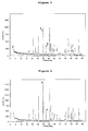
- the cell FB 560 (figure 2) according to the invention made from sample No 219 has highly superior capacities, especially at high rates, in comparison to the cell obtained with material from sample No 232 (figure 1).
Landscapes
- Chemical & Material Sciences (AREA)
- Chemical Kinetics & Catalysis (AREA)
- Electrochemistry (AREA)
- General Chemical & Material Sciences (AREA)
- Inorganic Chemistry (AREA)
- Engineering & Computer Science (AREA)
- Materials Engineering (AREA)
- Composite Materials (AREA)
- Manufacturing & Machinery (AREA)
- Crystallography & Structural Chemistry (AREA)
- Battery Electrode And Active Subsutance (AREA)
Abstract
Description
- The present invention relates to the field of rechargeable lithium secondary batteries and a process for the manufacture of electrodes for use in such lithium secondary batteries.
- Rechargeable lithium batteries find an increasing field of use in recent years. The possibility to miniaturize these devices makes them particularly attractive for various applications especially in the field of portable devices etc. Additionally they are strongly discussed for future use, especially in emerging high power applications like portable mechanical tools, hybrid electric vehicles etc.
- Present day rechargeable lithium batteries use as the anode for example a graphitic material into which lithium is reversibly inserted, or even lithium metal. As the cathode host material, a layered or framework transition metal oxide, like LiCoO2 or LiMn2O4 is commonly used (
Nishi et al. US 4,959,281 ).Goodenough et al. (US 5,910,382 ,US 6,391,493 andUS 6,514,640 ) disclosed LiFePO4 as a new and highly efficient cathode material. - The lithium metal phosphate electrodes for lithium secondary batteries in the prior art, however, often display poor rate behaviour, hence their capacity at high rates is often far away from the nominal capacity. To improve lithium ion motion in LiFePO4 resulting in higher lithium ion conductivity, various methods have been proposed. Though, increasing the percentage of conducting agents to values >30wt% results in packing densities too low for practical use. Further improvements have been disclosed by
Armand et al. (US 2004/0033360 ,EP1049182 andEP 132 5526 ), which describe carbon coated LiFePO4 particles. By contrast to the aforementioned layered structures of for example LiCoO2 LiFePO4 has an olivine structure. This means that the oxide ions form a hexagonal close packing (hcp) arrangement. The Fe ions form zig-zag chains of octahedra in alternate basal planes bridged by the tetrahedral phosphate groups. The lithium atoms occupy octahedral sites, located in the remaining basal planes. The strong covalent bonding between the oxygen and phosphorus in the phosphate units allows for greater stabilization of the structure compared to layered oxides like LiCoO2, where the oxide layers are more weakly bound. This strong covalency stabilizes the anti-bonding Fe3+/Fe2+ state through a Fe-O-P inductive effect. The result is inter alia that LiFePO4 has an available capacity of 160 mAh/g (theoretical capacity: 170 mAh/g) compared to LiCoO2 with 150 mAh/g (theoretical capacity: 274 mAh/g). In practice, LiFePO4 electrodes show a large dependency of discharge capacity on current rate. The performance of the electrode is affected by both the electrical conductivity and lithium ion diffusion within the electrode. - Recently,
Narang et al. (US 6,682,849 and6,337,156 )) proposed layered metal-oxide materials like LiCoO2 and the use of such metal oxide particles with a longest dimension of about 50 µm and 20 µm respectively, in the form of flakes as electrode materials. This particular geometry should compensate for the disadvantages in the use of the layered materials. However the available capacity of these electrodes could not be significantly improved. - On the other side, the lithium metal phosphate electrodes for lithium secondary batteries in the prior art, however, often display poor rate behaviour, hence their capacity at high rates is far away from the nominal capacity.
- Therefore, the problem underlying the invention is to provide novel positive electrodes, for use in lithium secondary batteries, which have a good high rate behaviour, so that the capacity of the positive electrode at a certain high rate is close to the nominal capacity.
- According to the present invention, this problem is solved by a positive electrode for a rechargeable lithium ion battery, wherein the positive electrode is comprised of single particles containing a compound of the formula LiMPO4, whereby M is a metal selected from the group consisting of Co, Ni, Mn, Fe, Ti or combinations of one or more of these metals, and whereby in a X-Ray diffraction chart of the electrode, the intensity ratio I1 : I2 of two selected
peaks peak 1 assigned to the (020) planes and I2 represents the intensity ofpeak 2 assigned to the (301) planes. In an especially preferred embodiment of the invention, this intensity ratio is larger than 15:1, preferably larger than 20:1, still more preferred larger than 24:1. - The afore-mentioned intensity ratio of these two peaks is an indicator for the presence of a so-called "texture effect" surprisingly found in the electrode according to the invention.
- This effect was observed for the (010) planes from the group of (0k0) planes in [0k0] direction (in the literature the designation [010] often stands exemplarily for reasons of convenience for the entire group of [0k0]), thereby enabling and increasing advantageously the Li-ion transfer through the plurality of particles forming the electrode according to the invention.
- Since it is in [010] direction where most of the Li-ion transfer occurs (D. Morgan et al., Electrochemical Solid State Letters, 7 (2), A30-A 32, (2004)), the preferred second set of crystal
planes generating peak 2 which is assigned to the signal with the intensity ratio I2 are perpendicular to the (020) planes and thus thepeak 2 represents the (301) crystal planes. - The texture effect in the electrode according to the invention decreases the diffusion length of Li-ions in [0k0] direction through the plurality of particles in the electrode by more than 10% compared to an electrode without such texture effect. Preferably the diffusion path is reduced by more than 25%, still more preferred by more than 50%. As a general concept in accordance with the present invention it was found that the larger the intensity ratio the shorter the overall diffusion length in the electrode.
- The term "texture effect" is an expression for the distribution of crystal planes in a collection of particles. This means that the majority of the crystal planes in a plurality of particles, preferably one single set of crystal planes, is present with an increased probability. A texture effect is therefore a colligative property of a plurality of particles. It is to be noted that an isolated particle does not display such a texture effect.
- The texture effect was also observed in electrodes comprising mixed (doped) phosphates like LiFe1-xM'yM"zM"'uPO4, which, for the purposes of the present invention, are understood to fall under the general formula LiMPO4 indicated in the foregoing. In these mixed or doped compounds, one or more different transition metals M', M", M'" like Co, Ni, Cu, Mn, Ti etc. occupy in different concentrations and numbers the octahedral positions of the iron octahedra in the olivine structure and wherein x, y, z and u represent a number between 0 and 1 and (y+z+u) ≤ x. It is understood that also isocharge and aliovalent substitutions are comprised within the above-mentioned general formulae.
- The term "particle" as used herein comprises any finely dispersed regularly or irregularly formed single particle which may be for example present in ordered or disordered crystalline, i.e. monocrystalline or polycrystalline, or in amorphous form. Most preferred, the particles consist essentially of a regular geometric monocrystal. The form of said monocrystal is not restricted to specific geometries, as far as the geometry is a regular one. Flat forms like platelets etc are, however, most preferred.
- The advantage of using a platelet shape consists in that the particles can easily be aligned with additional pressure upon manufacture of the positive electrode. Applying a uniaxial force to the platelets forces the platelets to rearrange in such a manner that their faces are aligned in the direction of the applied force. Another advantage of the platelet shape is that it provides a large surface area for a particular lattice plane. It provides also a small height perpendicular to the plate. At the same time, a higher maximum packing density up to 2.5g/cm3 is obtained using the platelet particles as compared with spherical, cylindrical or irregular-shaped particles. This corresponds to a larger energy density for the electrode comprising such particles.
- The platelet form forms upon pressure (see below) preferably closely packed regular or irregular stacks of platelet shaped particles, thus bringing the single particles in close contact to another. This arrangement forms a further, additional beneficial factor in decreasing the diffusion length, thereby increasing the capacity and conductivity of the electrode according to the invention. This alignment contributes to the observed texture effect compared to an electrode comprised of non-aligned particles. For example, the electrode according to the invention displays an intensity ratio I1:I2 of the two selected
peaks - In the context of the present invention, it is especially important that the alignment of the lattice planes of the particles is achieved by using the flat LiFePO4 particles with the [010] lattice direction along the normal of one of the particle surfaces. The afore-mentioned observations are not limited to LiFePO4 and/or its doped and mixed derivatives but can also be observed with other olivine structures such as LiMnPO4, Li-CoPO4, LiNiPO4, etc.
- The term "crystal plane" as used herein means a set of planes within the crystal lattice. Further definitions of crystallographic terms used herein can for example found in U. F. Kocks et al., "Texture and Anisotropy", Cambridge University Press 1998.
- It is preferred that the particles are coated onto a substrate upon preparation of the electrode which is also electrically conductive which enables a more facile application and alignment of the single particles. The form of the particles depends on the conditions of crystallisation which is subject to routine experimentation of a person skilled in the art. In a preferred embodiment, the particles are in the form of platelets. The size and aspect ratio of these platelets is in a first embodiment of the invention not of utmost importance to obtain the desired intensity ratio. However as a general rule, the more flat the particles are, the better for the purposes of the present invention.
- It is preferred that the d50 particle size of the particles is in the range of from 10 to 0.02 µm, more preferred from 3 to 0.02 µm. A detailed description of the measurement of the d50 particle size is given in unpublished German Patent Application
DE 103 53 266.8 . - In a further preferred embodiment of the invention the particles have a coating which comprises carbon which is in intimate contact with the particle surface and increases the capacity and conductivity of the electrode. The effect of carbon coating is described for example in
US 2004/0033360 . - The positive electrode (cathode) according to the invention comprising said particles further comprises a conductive substrate, like metal foils etc. which are essentially known for such purposes in the art. Said particles are coated and aligned on the substrate, whereby the thickness of the coating of the substrate with the particles is preferably >30 µm.
- Additionally, the coating further comprises carbon added during the manufacture process to further increase the conductivity of the electrode. The carbon content is preferably in the range of from 0.5 to 30 wt%, more preferred of from 1 to 10 wt% and most preferred from 2 to 5 wt% based on the total weight of the coating.
- It is especially preferred that the package density of the coating is >1.2 g/cm3, more preferred >1.7 g/cm3 to safeguard an intimate contact between the particles, which enhances the lithium ion transfer capacity. Also package densities >1.2 g/cm3, more preferred >1.7 g/cm3, are preferred to obtain lithium secondary batteries which display high enough volumetric energy densities for the batteries.
- The problem underlying the invention is further solved by a process for the manufacture of an electrode for use in a battery according to the invention, comprising the steps of
- a) Preparing particles of LiMPO4 with an essentially uniform and regular particle shape, optionally with a carbon coating
- b) Adding carbon to the particles and mixing
- c) Preparing a slurry by adding a binder and a solvent
- d) Application of the slurry on a substrate
- e) Drying
- f) Densifying of the dried slurry by applying uniaxial pressure, wherein the densifying step aligns the particles in a preferred direction.
- The densification is carried out by means of for example a platen press or a calender press or any other suitable pressing means is preferred since it ensures by the stronger alignment effect an increased physical contact of the particles compared to an electrode obtained in a process without densification. It is preferred that the pressure is a uniaxial pressure. This increases the electrical and ionic conductivity and capacity of the so-obtained electrode.
- The densification step is carried out with a line pressure applied to the coating in the range of from 3000 to 9000 N/cm, preferably 5000 to 7000 N/cm. The selected range for the line pressure applied provides the desired alignment of the particles in a preferred direction and generates thus the desired electrode structure. As explained in the foregoing, the particles are preferably present in the form of platelets. The densification step was repeated up to 4 times.
- In another less preferred embodiment of the process according to the invention, the densification step f) is not carried out. An alignment of the particles and also the occurrence of a "texture effect" are also observed which can be ascribed to the inherently occurring densification during the manufacturing process, when the particles are aligned within the binder. The magnitude of the texture effect is, however, smaller than the magnitude observed with densification.
- The alignment and especially the densification thus increases the measured "texture effect" described in the foregoing in more detail.
- The amount of carbon added in step b) of the process according to the invention is preferably in the range of from 0.2 - 30 wt % based on the total amount of carbon and the particles. It has further been found that the amount of binder in step c) is preferably in the range of from 2 to 7 wt % based on the total amount of carbon and/or binder and the particles. This amount proved to be advantageous to achieve sufficient conductivity in the electrode and thus enables retrieving the capacity of the electrodes according to the invention.
- The invention is further illustrated by way of the following figures and examples which are not meant to limit the scope of the invention. It is understood that not only the specifically disclosed features of the present invention but also combinations thereof are comprised within the scope of the invention. Drawings
- Fig. 1 shows a voltage curve for a lithium secondary battery of the prior art;
- Fig. 2 shows a voltage curve for a lithium secondary battery according to the invention;
- Fig. 3 shows an X-Ray Diffraction chart of an electrode comprising LiFePO4 of the prior art;
- Fig. 4 shows an X-Ray Diffraction chart of an electrode manufactured without final densification;
- Fig. 5 shows an X-Ray Diffraction chart of an electrode manufactured with a final densification according to the invention.
- The particles of LiFePO4 (and its doped derivatives) have an olivine structure in the space group Pnma (No. 62) with setting 1 (a = 10.332 Å, b = 6.010 Å, c = 4.694 Å). LiFePO4 particles were obtained from Süd-Chemie AG, Germany.
- For the purpose of the present invention, the intensity ratio of the two selected perpendicular peaks was determined upon selection of the signal assigned to the (020) crystal planes and the perpendicular crystal planes were the (301) planes. The (020) crystal planes were found to be always superimposed to the (211) planes which was therefore also taken into account upon calculating the intensity ratio of the (020) planes.
- X-Ray diffraction (XRD) measurements were carried out on a Philips X'pert PW 3050 instrument with CuKα radiation (30 kV, 30 mA) with a graphite monochromator and a variable slit.
- Upon measurement of the electrode foils (substrate + particle coating), the foils are arranged tangential and flat with respect to the focussing circle according to the Bragg-Brentano condition.
- Usual conditions for the manufacture of lithium batteries according to the present invention are as follows:
- The binder used in the process for the manufacture of electrodes according to the invention is not specifically limited to certain classes of compounds. Any binder suitable for that purpose can be used. Representative but non-limiting examples of binders are polytetrafluoroethylene (PTFE), polyvinylidene difluoride (PVdF), polyvinylidene fluoride hexafluoropropylene copolymers, ethylene propylene diene ter-polymer (EPDM) and tetrafluoroethylene-hexafluoropropylene copolymers etc.
- The carbon added in the process for the manufacture of electrodes according to the invention is not limited to specific grades, carbon sources or manufacturers thereof. Representative but non-limiting examples of carbon are graphite, acetylene black and carbon black.
- Electrodes were prepared by mixing 90 parts per weight LiFePO4 or carbon coated LiFePO4 together with 5 parts of carbon. 5 parts of a binder were diluted in N-methyl-2-pyrrolidon solution and added to the mixture. The mixture was kneaded to give a slurry. The slurry was applied by a doctor blade to an aluminium collector foil serving as a collector. The film was dried at 60°C under reduced pressure of 500 mbar for 2 h.
- A calender press was used for densification. But any other press like for example a platen press is suitable as well. The applied line pressure was in the range of from 3000 to 9000 N/cm, preferably from 5000 to 7000 N/cm. The target value for the coating (active material) packing density was >1.2 g/cm3 or higher, more preferably >1.7 g/cm3.
- The electrodes were dried for 2 more hours under vacuum, preferably at elevated temperatures of about 100°C. Cells were assembled as "coffee bag" cells (batteries), which consist of an aluminium coated polyethylene bag. Lithium metal was used as the counter electrode. 1M LiPF6 was used as electrolyte in a 1:1 mixture of ethylenecarbonate (EC):diethylcarbonate (DEC). In each battery one layer of a microporous polypropylene-foil (
Celgard 2500;Celgard 2500 is a trademark) having lithium ion permeability was used as the separator. The bags were sealed using a vacuum-sealing machine. - Measurements were performed in a temperature-controlled cabinet at 20°C using a Maccor Lab tester Series 4000 battery test system. Voltage range for cycling was between 2.0 V and 4.0 V.
- The characteristic properties of LiFePO4 particles used in the manufacture of the batteries mentioned above are shown in table 1:
Table 1: Characteristic Properties of LiFePO4 particles Sample No d50 particle size (µm) BET (m2/g) Surface C (%) 232 0.91 17 3.2 219 1.76 8 2.7 - All particle powders were characterized by X-Ray Powder Diffraction (XRD) and showed the same peak (signal) positions in the X-Ray diffraction chart diagram. 2θ values of all peaks and their relative intensities are identical. The XRD diagrams did not show signals originating from impurities or other lithium-iron-phosphate phases.
- Electrodes were prepared from each particle sample according to the general process as described in the foregoing. The film thickness obtained and the density of the active material calculated for the LiFePO4 electrodes is given in table 2:
Table 2: Cell characteristics Sample No Cell name Density (g/cc) Film thickness d(µm) 232 FB087 2.11 61 219 FB560 2.28 60 - The particles and the electrodes obtained from the different particle powders were characterized by XRD analysis.
- Figure 3 (sample No. 232) shows an X-Ray diffraction chart of an electrode manufactured with conventional LiFePO4 particles and without densification which shows no texture effect for the
corresponding peaks Peak 1 has an intensity I1 and peak 2 has an intensity I2. - The position and the intensity of the XRD signals for
sample 219 measured as a manufactured electrode made without further (final) densification step (figure 4) and with densification step (figure 5) are identical to those found in prior art (see e.g. Chichagov A.V. et al. Information-Calculating System on Crystal Structure Data of Minerals (MINCRYST) - Kristal-lographiya, v.35, n.3, 1990, p.610-616). - As can be seen from the diagrams in figures 4 and 5, electrodes made from sample No. 219 showed a marked difference in signal intensity before (figure 4) and after (figure 5) densification. All signals have the same 2θ values. Figure 4 shows an intensity ratio of the selected peaks 1 (020 + 211) and 2 (301) of 9:1. Figure 5, which was recorded after densification, showed an intensity ratio of these two
peaks - Table 3 indicates the difference in the intensity ratio before and after the densification step for various samples which confirms the aforementioned findings:
Table 3: Change in intensity ratio with and without densification of the electrodes Sample No Intensity ratio I1(020 + 211)/I2 (301) Intensity ratio I1(020 + 211)/I2 (301) Electrode without further densification Electrode with densification 232 2.6 / 1 3.9 / 1 219 7.7 / 1 23 / 1 - The cells with the electrodes obtained from the particle samples were electrochemically characterized by measuring their respective capacities.
- The capacities obtained by cycling at C/5, 1C and 2C rate are listed in table 4 and are shown in figures 1 and 2. Figure 1 shows the capacities as measured with cells comprising electrodes manufactured with material from
sample No 232. The capacity of a cell according to the invention is shown in figure 2 (sample No 219).Table 4: Capacities of various cells Sample No Cell name C/5 C 2C 232 FB087 123 95 50 219 FB560 151 134 103 - As can be seen from the values in table 4 and the figures 1 and 2, the cell FB 560 (figure 2) according to the invention made from
sample No 219 has highly superior capacities, especially at high rates, in comparison to the cell obtained with material from sample No 232 (figure 1). - This effect may be ascribed to minimized diffusion paths inside the solid and to a maximized electrochemically active surface. Therefore the capacity increases dramatically at high rate.
Claims (13)
- Positive electrode for a rechargeable lithium ion battery comprised of single particles containing a compound of the formula LiMPO4, whereby M is a metal selected from the group consisting of Co, Ni, Mn, Fe, Ti or combinations thereof, and whereby in a X-Ray diffraction chart of the electrode the intensity ratio I1 : I2 of two selected peaks 1 and 2 is larger than 9:1 and wherein I1 represents essentially the intensity of peak 1 assigned to the (020) planes and I2 represents the intensity of peak 2 assigned to the (301) planes.
- Electrode according to claim 1, wherein the intensity ratio is larger than 15:1, preferably larger than 20:1.
- Electrode according to claim 1 or 2, wherein LiMPO4 represents LiFePO4.
- Electrode according to one of the preceding claims, wherein the d50 particle size of the single particles is in the range of from 10 to 0.02 µm.
- Electrode according to claim 4, wherein the particles have an additional carbon coating on their surface.
- Electrode according to one of the preceding claims, wherein the particles are coated on a substrate and whereby the coating thickness is >30 µm.
- Electrode according to claim 6, wherein the package density of the coating is >1,2 g/cm3, preferably >2,0 g/cm3.
- Electrode according to one of the preceding claims, wherein the particles are aligned in the form of regular or irregular stacks.
- Lithium secondary ion battery comprising a negative electrode, a positive electrode according to any of the preceding claims and an electrolyte.
- Process for the manufacture of a positive electrode for use in a battery according to claim 9, comprising the steps ofa) Preparing particles of LiMPO4, whereby M is a metal selected from the group consisting of Co, Ni, Mn, Fe or combinations thereof, with an essentially uniform platelet shape, optionally with a carbon coatingb) Adding carbon to the particles and mixingc) Preparing a slurry by adding a binder and a solventd) Applying the slurry on a substratee) Dryingf) Densifying the dried slurry by applying uniaxial pressurecharacterized in that the densifying step f) aligns the particles in a preferred orientation.
- Process according to claim 10, wherein the amount of carbon added in step b) is in the range of from 0.2 - 30 wt % based on the total amount of carbon and the particles.
- Process according to claim 10 or 11, wherein the amount of binder in step c) is in the range of from 2 to 7 wt % based on the total amount of carbon and/or binder and the particles.
- Process according to one of the preceding claims, whereby the line pressure applied in step f) is in the range of from 3000 to 9000 N/cm, preferably in the range of from 5000 to 7000 N/cm.
Priority Applications (8)
| Application Number | Priority Date | Filing Date | Title |
|---|---|---|---|
| EP05010498A EP1722428A1 (en) | 2005-05-13 | 2005-05-13 | Lithium secondary battery and electrodes for use therein |
| TW095114032A TWI338401B (en) | 2005-05-13 | 2006-04-20 | Lithium secondary battery and electrodes for use therein |
| US11/919,777 US20090286159A1 (en) | 2005-05-13 | 2006-05-11 | Lithium secondary battery and electrodes for use therein |
| CA2617134A CA2617134C (en) | 2005-05-13 | 2006-05-11 | Lithium secondary battery and electrodes for use therein |
| EP06724799A EP1883984A1 (en) | 2005-05-13 | 2006-05-11 | Lithium secondary battery and electrodes for use therein |
| CN2006800155699A CN101189747B (en) | 2005-05-13 | 2006-05-11 | Lithium secondary battery and electrodes for use therein |
| PCT/EP2006/004446 WO2006119995A1 (en) | 2005-05-13 | 2006-05-11 | Lithium secondary battery and electrodes for use therein |
| JP2008510498A JP5419445B2 (en) | 2005-05-13 | 2006-05-11 | Lithium secondary battery and electrode used therefor |
Applications Claiming Priority (1)
| Application Number | Priority Date | Filing Date | Title |
|---|---|---|---|
| EP05010498A EP1722428A1 (en) | 2005-05-13 | 2005-05-13 | Lithium secondary battery and electrodes for use therein |
Publications (1)
| Publication Number | Publication Date |
|---|---|
| EP1722428A1 true EP1722428A1 (en) | 2006-11-15 |
Family
ID=35197876
Family Applications (2)
| Application Number | Title | Priority Date | Filing Date |
|---|---|---|---|
| EP05010498A Withdrawn EP1722428A1 (en) | 2005-05-13 | 2005-05-13 | Lithium secondary battery and electrodes for use therein |
| EP06724799A Withdrawn EP1883984A1 (en) | 2005-05-13 | 2006-05-11 | Lithium secondary battery and electrodes for use therein |
Family Applications After (1)
| Application Number | Title | Priority Date | Filing Date |
|---|---|---|---|
| EP06724799A Withdrawn EP1883984A1 (en) | 2005-05-13 | 2006-05-11 | Lithium secondary battery and electrodes for use therein |
Country Status (7)
| Country | Link |
|---|---|
| US (1) | US20090286159A1 (en) |
| EP (2) | EP1722428A1 (en) |
| JP (1) | JP5419445B2 (en) |
| CN (1) | CN101189747B (en) |
| CA (1) | CA2617134C (en) |
| TW (1) | TWI338401B (en) |
| WO (1) | WO2006119995A1 (en) |
Cited By (10)
| Publication number | Priority date | Publication date | Assignee | Title |
|---|---|---|---|---|
| WO2010051565A1 (en) * | 2008-11-03 | 2010-05-06 | Imara Corporation | Lithium secondary batteries with positive electrode compositions and their methods of manufacturing |
| WO2010094987A1 (en) * | 2009-02-20 | 2010-08-26 | Toyota Jidosha Kabushiki Kaisha | Lithium metal (ii) phosphate crystal material |
| WO2010130684A1 (en) * | 2009-05-11 | 2010-11-18 | Süd-Chemie AG | Composite material containing a mixed lithium-metal oxide |
| CN102881904A (en) * | 2012-10-28 | 2013-01-16 | 桂林理工大学 | Method for preparing double-carbon-source coated LiFePO4/C composite anode material through two-step sintering |
| US8715525B2 (en) | 2010-06-30 | 2014-05-06 | Semiconductor Energy Laboratory Co., Ltd. | Manufacturing method of electrode material |
| US8808917B2 (en) | 2009-09-11 | 2014-08-19 | Semiconductor Energy Laboratory Co., Ltd. | Power storage device having olivine type positive electrode active material with oriented crystal structure |
| US9051184B2 (en) | 2006-12-22 | 2015-06-09 | Umicore | Synthesis of crystalline nanometric LiFeMPO4 |
| US9147879B2 (en) | 2009-06-25 | 2015-09-29 | Nagasaki University | Composite nano porous electrode material, process for production thereof, and lithium ion secondary battery |
| EP2562856A4 (en) * | 2010-04-21 | 2016-10-12 | Lg Chemical Ltd | Anode active material for secondary battery, and lithium secondary battery comprising same |
| US9556536B2 (en) | 2011-09-09 | 2017-01-31 | Semiconductor Energy Laboratory Co., Ltd. | Positive electrode for lithium secondary battery, manufacturing method thereof, and lithium secondary battery |
Families Citing this family (13)
| Publication number | Priority date | Publication date | Assignee | Title |
|---|---|---|---|---|
| ATE513321T1 (en) * | 2007-03-19 | 2011-07-15 | Umicore Nv | ROOM TEMPERATURE SINGLE PHASE LI INSERT/EXTRACTION MATERIAL FOR USE IN A LI BASED BATTERY |
| US7662510B2 (en) * | 2007-09-20 | 2010-02-16 | Celgard Llc | X-ray sensitive battery separator and a method for detecting the position of a separator in a battery |
| JP5383217B2 (en) * | 2008-01-28 | 2014-01-08 | 住友化学株式会社 | Positive electrode active material, sodium secondary battery, and olivine-type phosphate production method |
| CN101655468B (en) * | 2008-08-23 | 2011-08-17 | 比亚迪股份有限公司 | Method for identifying failure causes of secondary battery |
| WO2011099585A1 (en) * | 2010-02-12 | 2011-08-18 | 三菱化学株式会社 | Nonaqueous electrolyte solution, and nonaqueous electrolyte secondary battery |
| US9166228B2 (en) * | 2010-11-05 | 2015-10-20 | Purdue Research Foundation | Method of exploiting particle morphology to optimize granular structure and charge/discharge performance of lithium ion battery cathodes |
| KR101924989B1 (en) * | 2011-01-07 | 2018-12-04 | 가부시키가이샤 한도오따이 에네루기 켄큐쇼 | Method for manufacturing power storage device |
| US20120212941A1 (en) * | 2011-02-22 | 2012-08-23 | Jomar Reschreiter | Cordless, portable, rechargeable food heating lamp |
| JP5998428B2 (en) * | 2011-03-24 | 2016-09-28 | 凸版印刷株式会社 | Non-aqueous electrolyte secondary battery positive electrode, non-aqueous electrolyte secondary battery, non-aqueous electrolyte secondary battery positive electrode manufacturing method, non-aqueous electrolyte secondary battery positive ink, non-aqueous electrolyte secondary battery For manufacturing positive electrode for automobile |
| JP6249388B2 (en) * | 2011-07-28 | 2017-12-20 | 株式会社村田製作所 | Positive electrode for lithium ion secondary battery, lithium ion secondary battery, battery pack, electric vehicle, electric power storage system, electric tool and electronic device |
| JP5807749B2 (en) | 2011-12-08 | 2015-11-10 | ソニー株式会社 | Positive electrode for non-aqueous electrolyte secondary battery, non-aqueous electrolyte secondary battery, battery pack, electric vehicle, power storage system, electric tool, and electronic device |
| JP2015092510A (en) * | 2015-01-14 | 2015-05-14 | シャープ株式会社 | Nonaqueous electrolyte secondary battery |
| WO2021053514A1 (en) | 2019-09-16 | 2021-03-25 | InCoR Lithium | Selective lithium extraction from brines |
Citations (4)
| Publication number | Priority date | Publication date | Assignee | Title |
|---|---|---|---|---|
| JPH0684515A (en) * | 1992-09-03 | 1994-03-25 | Sanyo Electric Co Ltd | Nonaqueous electrolyte secondary cell |
| US5910382A (en) * | 1996-04-23 | 1999-06-08 | Board Of Regents, University Of Texas Systems | Cathode materials for secondary (rechargeable) lithium batteries |
| WO2002027823A1 (en) * | 2000-09-26 | 2002-04-04 | HYDRO-QUéBEC | Method for synthesis of carbon-coated redox materials with controlled size |
| JP2003292307A (en) * | 2002-01-31 | 2003-10-15 | Nippon Chem Ind Co Ltd | Ferrous phosphate hydrate crystal, production method therefor, and method for producing lithium/iron/ phosphorus-based complex oxide |
Family Cites Families (16)
| Publication number | Priority date | Publication date | Assignee | Title |
|---|---|---|---|---|
| JP2674793B2 (en) * | 1988-08-31 | 1997-11-12 | ソニー 株式会社 | Non-aqueous electrolyte battery |
| US6514640B1 (en) * | 1996-04-23 | 2003-02-04 | Board Of Regents, The University Of Texas System | Cathode materials for secondary (rechargeable) lithium batteries |
| JPH1125983A (en) * | 1997-07-04 | 1999-01-29 | Japan Storage Battery Co Ltd | Active material for lithium battery |
| US6337156B1 (en) * | 1997-12-23 | 2002-01-08 | Sri International | Ion battery using high aspect ratio electrodes |
| JP4103168B2 (en) * | 1998-03-31 | 2008-06-18 | 宇部興産株式会社 | Non-aqueous secondary battery and manufacturing method thereof |
| JP2001222994A (en) * | 2000-02-08 | 2001-08-17 | Shin Kobe Electric Mach Co Ltd | Non-aqueous electrolyte secondary battery |
| JP3982165B2 (en) * | 2000-10-05 | 2007-09-26 | ソニー株式会社 | Solid electrolyte battery |
| JP4491949B2 (en) * | 2000-10-06 | 2010-06-30 | ソニー株式会社 | Method for producing positive electrode active material and method for producing non-aqueous electrolyte battery |
| JP4075451B2 (en) * | 2001-05-15 | 2008-04-16 | 株式会社豊田中央研究所 | Lithium secondary battery |
| US9391325B2 (en) * | 2002-03-01 | 2016-07-12 | Panasonic Corporation | Positive electrode active material, production method thereof and non-aqueous electrolyte secondary battery |
| JP4197237B2 (en) * | 2002-03-01 | 2008-12-17 | パナソニック株式会社 | Method for producing positive electrode active material |
| JP4058680B2 (en) * | 2002-08-13 | 2008-03-12 | ソニー株式会社 | Method for producing positive electrode active material and method for producing non-aqueous electrolyte secondary battery |
| JP4190930B2 (en) * | 2003-03-28 | 2008-12-03 | 住友大阪セメント株式会社 | Lithium metal phosphate compound fine particles and method for producing the same |
| JP2004335344A (en) * | 2003-05-09 | 2004-11-25 | Sanyo Electric Co Ltd | Positive electrode for lithium secondary battery, and lithium secondary battery |
| CA2791156C (en) * | 2003-12-23 | 2015-12-15 | Universite De Montreal | Process for preparing electroactive insertion compounds and electrode materials obtained therefrom |
| US8323832B2 (en) * | 2005-08-08 | 2012-12-04 | A123 Systems, Inc. | Nanoscale ion storage materials |
-
2005
- 2005-05-13 EP EP05010498A patent/EP1722428A1/en not_active Withdrawn
-
2006
- 2006-04-20 TW TW095114032A patent/TWI338401B/en not_active IP Right Cessation
- 2006-05-11 WO PCT/EP2006/004446 patent/WO2006119995A1/en active Application Filing
- 2006-05-11 CN CN2006800155699A patent/CN101189747B/en not_active Expired - Fee Related
- 2006-05-11 JP JP2008510498A patent/JP5419445B2/en not_active Expired - Fee Related
- 2006-05-11 US US11/919,777 patent/US20090286159A1/en not_active Abandoned
- 2006-05-11 CA CA2617134A patent/CA2617134C/en not_active Expired - Fee Related
- 2006-05-11 EP EP06724799A patent/EP1883984A1/en not_active Withdrawn
Patent Citations (4)
| Publication number | Priority date | Publication date | Assignee | Title |
|---|---|---|---|---|
| JPH0684515A (en) * | 1992-09-03 | 1994-03-25 | Sanyo Electric Co Ltd | Nonaqueous electrolyte secondary cell |
| US5910382A (en) * | 1996-04-23 | 1999-06-08 | Board Of Regents, University Of Texas Systems | Cathode materials for secondary (rechargeable) lithium batteries |
| WO2002027823A1 (en) * | 2000-09-26 | 2002-04-04 | HYDRO-QUéBEC | Method for synthesis of carbon-coated redox materials with controlled size |
| JP2003292307A (en) * | 2002-01-31 | 2003-10-15 | Nippon Chem Ind Co Ltd | Ferrous phosphate hydrate crystal, production method therefor, and method for producing lithium/iron/ phosphorus-based complex oxide |
Non-Patent Citations (4)
| Title |
|---|
| ANDERSSON A S ET AL: "Lithium extraction/insertion in LiFePO4: an X-ray diffraction and Mss", SOLID STATE IONICS, NORTH HOLLAND PUB. COMPANY. AMSTERDAM, NL, vol. 130, no. 1,2, May 2000 (2000-05-01), pages 41 - 52, XP002169165, ISSN: 0167-2738 * |
| MORGAN,D. ETAL.: "Li Conductivity in LixMPO4 ( M = Mn,Fe,Co,Ni) Olivine Materials", ELECTROCHEMICAL AND SOLID-STATE LETTERSD, vol. 7, no. 2, 2004, pages A30 - A32, XP009056734 * |
| PATENT ABSTRACTS OF JAPAN vol. 018, no. 332 (E - 1567) 23 June 1994 (1994-06-23) * |
| PATENT ABSTRACTS OF JAPAN vol. 2003, no. 12 5 December 2003 (2003-12-05) * |
Cited By (12)
| Publication number | Priority date | Publication date | Assignee | Title |
|---|---|---|---|---|
| US9051184B2 (en) | 2006-12-22 | 2015-06-09 | Umicore | Synthesis of crystalline nanometric LiFeMPO4 |
| WO2010051565A1 (en) * | 2008-11-03 | 2010-05-06 | Imara Corporation | Lithium secondary batteries with positive electrode compositions and their methods of manufacturing |
| US9099738B2 (en) | 2008-11-03 | 2015-08-04 | Basvah Llc | Lithium secondary batteries with positive electrode compositions and their methods of manufacturing |
| WO2010094987A1 (en) * | 2009-02-20 | 2010-08-26 | Toyota Jidosha Kabushiki Kaisha | Lithium metal (ii) phosphate crystal material |
| WO2010130684A1 (en) * | 2009-05-11 | 2010-11-18 | Süd-Chemie AG | Composite material containing a mixed lithium-metal oxide |
| US9147879B2 (en) | 2009-06-25 | 2015-09-29 | Nagasaki University | Composite nano porous electrode material, process for production thereof, and lithium ion secondary battery |
| US8808917B2 (en) | 2009-09-11 | 2014-08-19 | Semiconductor Energy Laboratory Co., Ltd. | Power storage device having olivine type positive electrode active material with oriented crystal structure |
| EP2562856A4 (en) * | 2010-04-21 | 2016-10-12 | Lg Chemical Ltd | Anode active material for secondary battery, and lithium secondary battery comprising same |
| US8715525B2 (en) | 2010-06-30 | 2014-05-06 | Semiconductor Energy Laboratory Co., Ltd. | Manufacturing method of electrode material |
| US9556536B2 (en) | 2011-09-09 | 2017-01-31 | Semiconductor Energy Laboratory Co., Ltd. | Positive electrode for lithium secondary battery, manufacturing method thereof, and lithium secondary battery |
| US9935313B2 (en) | 2011-09-09 | 2018-04-03 | Semiconductor Energy Laboratory Co., Ltd. | Positive electrode for lithium secondary battery, manufacturing method thereof, and lithium secondary battery |
| CN102881904A (en) * | 2012-10-28 | 2013-01-16 | 桂林理工大学 | Method for preparing double-carbon-source coated LiFePO4/C composite anode material through two-step sintering |
Also Published As
| Publication number | Publication date |
|---|---|
| US20090286159A1 (en) | 2009-11-19 |
| CA2617134A1 (en) | 2006-11-16 |
| CA2617134C (en) | 2014-12-09 |
| TW200703753A (en) | 2007-01-16 |
| WO2006119995A1 (en) | 2006-11-16 |
| JP5419445B2 (en) | 2014-02-19 |
| TWI338401B (en) | 2011-03-01 |
| CN101189747B (en) | 2012-08-15 |
| EP1883984A1 (en) | 2008-02-06 |
| CN101189747A (en) | 2008-05-28 |
| JP2008541364A (en) | 2008-11-20 |
Similar Documents
| Publication | Publication Date | Title |
|---|---|---|
| EP1722428A1 (en) | Lithium secondary battery and electrodes for use therein | |
| US11362366B2 (en) | Secondary battery composite electrolyte, secondary battery, and battery pack | |
| US9508980B2 (en) | Graphite particles and lithium secondary battery using the same as negative | |
| KR101510510B1 (en) | Method of producing electrode active substance | |
| CN103460458B (en) | The manufacture method of active material, electrode, lithium rechargeable battery and active material | |
| US11329316B2 (en) | Secondary battery composite electrolyte, secondary battery, and battery pack | |
| EP3096380A1 (en) | Electrode active material, electrode and energy storage device including the same, and method of preparing the electrode active material | |
| EP1959513B1 (en) | Composite anode active material,method of preparing the same,and anode and lithium battery containing the material | |
| KR101785269B1 (en) | Composite negative electrode active material, method for preparing the same, and lithium battery including the same | |
| WO2024195744A1 (en) | Solid-electrolyte battery | |
| US20230344083A1 (en) | All-solid-state rechargeable battery, stacked rechargeable all-solid-state battery, and manufacturing method thereof | |
| WO2024117146A1 (en) | Solid electrolyte, solid electrolyte for positive electrode, composite, positive electrode for power storage element, and power storage element | |
| KR20240128664A (en) | Negative electrode material for rechargeable lithium ion battery, method for manufacturing the same and method for using the same |
Legal Events
| Date | Code | Title | Description |
|---|---|---|---|
| PUAI | Public reference made under article 153(3) epc to a published international application that has entered the european phase |
Free format text: ORIGINAL CODE: 0009012 |
|
| AK | Designated contracting states |
Kind code of ref document: A1 Designated state(s): AT BE BG CH CY CZ DE DK EE ES FI FR GB GR HU IE IS IT LI LT LU MC NL PL PT RO SE SI SK TR |
|
| AX | Request for extension of the european patent |
Extension state: AL BA HR LV MK YU |
|
| 17P | Request for examination filed |
Effective date: 20070301 |
|
| AKX | Designation fees paid |
Designated state(s): AT BE BG CH CY CZ DE DK EE ES FI FR GB GR HU IE IS IT LI LT LU MC NL PL PT RO SE SI SK TR |
|
| RAP1 | Party data changed (applicant data changed or rights of an application transferred) |
Owner name: SANYO COMPONENT EUROPE GMBH Owner name: SANYO ELECTRIC CO., LTD. Owner name: CLARIANT PRODUKTE (DEUTSCHLAND) GMBH |
|
| 17Q | First examination report despatched |
Effective date: 20130916 |
|
| RAP1 | Party data changed (applicant data changed or rights of an application transferred) |
Owner name: CLARIANT PRODUKTE (DEUTSCHLAND) GMBH |
|
| STAA | Information on the status of an ep patent application or granted ep patent |
Free format text: STATUS: THE APPLICATION IS DEEMED TO BE WITHDRAWN |
|
| 18D | Application deemed to be withdrawn |
Effective date: 20160621 |