EP1722181B1 - Connection between cooled pipe and uncooled pipe in a double-pipe heat exchanger - Google Patents
Connection between cooled pipe and uncooled pipe in a double-pipe heat exchanger Download PDFInfo
- Publication number
- EP1722181B1 EP1722181B1 EP06006670.1A EP06006670A EP1722181B1 EP 1722181 B1 EP1722181 B1 EP 1722181B1 EP 06006670 A EP06006670 A EP 06006670A EP 1722181 B1 EP1722181 B1 EP 1722181B1
- Authority
- EP
- European Patent Office
- Prior art keywords
- pipe
- connection
- accordance
- double
- wall
- Prior art date
- Legal status (The legal status is an assumption and is not a legal conclusion. Google has not performed a legal analysis and makes no representation as to the accuracy of the status listed.)
- Expired - Lifetime
Links
Images
Classifications
-
- F—MECHANICAL ENGINEERING; LIGHTING; HEATING; WEAPONS; BLASTING
- F28—HEAT EXCHANGE IN GENERAL
- F28D—HEAT-EXCHANGE APPARATUS, NOT PROVIDED FOR IN ANOTHER SUBCLASS, IN WHICH THE HEAT-EXCHANGE MEDIA DO NOT COME INTO DIRECT CONTACT
- F28D7/00—Heat-exchange apparatus having stationary tubular conduit assemblies for both heat-exchange media, the media being in contact with different sides of a conduit wall
- F28D7/10—Heat-exchange apparatus having stationary tubular conduit assemblies for both heat-exchange media, the media being in contact with different sides of a conduit wall the conduits being arranged one within the other, e.g. concentrically
- F28D7/106—Heat-exchange apparatus having stationary tubular conduit assemblies for both heat-exchange media, the media being in contact with different sides of a conduit wall the conduits being arranged one within the other, e.g. concentrically consisting of two coaxial conduits or modules of two coaxial conduits
-
- F—MECHANICAL ENGINEERING; LIGHTING; HEATING; WEAPONS; BLASTING
- F28—HEAT EXCHANGE IN GENERAL
- F28F—DETAILS OF HEAT-EXCHANGE AND HEAT-TRANSFER APPARATUS, OF GENERAL APPLICATION
- F28F9/00—Casings; Header boxes; Auxiliary supports for elements; Auxiliary members within casings
- F28F9/26—Arrangements for connecting different sections of heat-exchange elements, e.g. of radiators
Definitions
- This invention relates to an innovative connection between cooled pipe and uncooled pipe in a double-pipe heat exchanger of the type used, for example, to cool high temperature cracking gas in so-called Transfer Line Exchangers (TLEs).
- TLEs Transfer Line Exchangers
- the double-wall pipe comprises an internal pipe traveled by the fluid to be cooled (for example, cracking gas coming out of an oven) and an external pipe delimiting with the internal one the airspace traveled by the cooling fluid (for example, water) with the cooling fluid injected into the air space through a union on the side wall of the outermost pipe and in general near the inlet end of the double-wall cooled pipe.
- the cooling fluid is then taken from the air space near the output end of the double-wall pipe.
- the double-wall pipe must be connected upstream with a single-wall pipe inlet pipe feeding the hot fluid to be cooled and which is at a relatively high temperature. It is to be considered for example, that, in ethylene plants, the incoming hot fluid has a temperature over 800°C.
- the gas to be cooled meets on its path irregularities which disturb the gas flow and cause formation of coke in the apparatus.
- the irregularity consists of the floating 'sleeve' arranged generally at the inlet of the double pipe and capable of absorbing the differential dilation between the outer wall of the cone in contact with the air and the inner wall of the pipe in contact with the hot gas.
- the coke by attrition, obstructs dilations of the 'sleeve' which occur at each startup of the exchanger and compromise mechanical integrity.
- coke formation causes fouling and decrease in the efficiency of the exchanger.
- the general purpose of this invention is to remedy the above-mentioned shortcomings by making available a connection for a heat exchanger with double-wall pipes and having a simple, economical structure and which at the same time is durable and resistant to the operating temperatures of the exchanger in every part thereof.
- Another purpose of this invention is to make available a connection for the double-pipe heat exchanger allowing avoidance of the formation of coke as well as high efficiency.
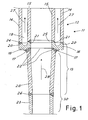
- FIG 1 shows a longitudinal cross-section view of the connation zone between the double-wall pipe of he exchanger and the high-temperature fluid inlet duct.
- the figure shows one part of a heat exchanger in the connection zone 11 of a double-wall pipe designed, for example, to be used for cooling high-temperature cracking gas (over 800°C).
- the exchanger comprises a double-wall pipe 12 made up of an internal pipe 15 traveled by the fluid to be cooled and an external pipe 14 defining with the internal pipe 15 an air space 19 traveled by a cooling fluid.
- the double-wall pipe 12 must be connected to a single-wall pipe 23 for inlet of the fluid to be cooled.
- a union connection 13 is used comprising a connection part 16 and, advantageously but not exclusively, a union sleeve 28.
- the sleeve 28 together with the inlet pipe 23 form an inlet duct 30 for the hot fluid to the double-wall pipe 12.
- the pipe 12 is connected at its opposite end to an outlet duct for the cooled cracking gas (not shown in the figure).
- This outlet union can be realized in accordance with the prior art in the field or similarly to the union 11 and is not further described.
- connection part 16 is not realized as a fork but as a U to form a bottom wall 18 of the air space 19 virtually transversal to the pipe axis 12.
- the bottom wall 18 forms in fact a ring extending transversely to the pipe 12 in such a manner as to delimit in longitudinal direction the extension of the air space 19.
- the end 22 of the inlet duct 30 is then welded to the connection part 16 through the weld 17 at said bottom wall 18 of the of the air space 19.
- inlet duct 30 could be made up exclusively of an inlet pipe similar to the pipe 23 if it were appropriately sized and insertion in the sleeve connection 28 were not necessary.
- this stratagem allows always keeping the temperature of the material of the connection part 16 at a sufficiently low level to avoid that it might have to undergo unacceptable thermal stresses, plasticization and creep phenomena without the need of refractory shielding or flow switches.
- connection part 16 never reaches excessively high temperatures (never more than 500°C even in the presence of inlet fluid over 800°C).
- the need was seen that the distance of the weld 17 from the air space bottom 19 be on the order of the wall thickness 15.
- the thickness of the material of the connection part 16 between the cooling fluid (in the air space) and the weld 17 be always less than 30 mm and preferably less than 15 mm. It was found extremely advantageous to choose the thickness between 10 mm and 12 mm.
- the weld end 22 of the inlet duct 30 is metallized in 6617 alloy to compensate for the differential dilations which can occur between the material of the sleeve 28 (made advantageously of 8811 alloy or 8810 alloy) and the material of the connection part 16 (realized advantageously of 2.25 Cr - 0.5 Mo material thanks to the fact that the temperature in the connection point is kept sufficiently low to allow use of said material).
- connection part 16 has an annular form with U cross section in such a manner as to define two annular shanks 20, 21 each welded to one of the two pipes 14, 15 of the double-wall pipe and an appropriately beveled edge for welding.
- the thickness of the 'pipe plate' is limited to achieve an acceptable temperature profile.
- shank 20 is welded to the external pipe 14 with the weld 24 while the shank 21 is welded to the internal pipe 15 with weld 25.
- Each shank 20, 21 projects axially from the bottom wall 18 which in actual fact forms the U bottom.
- the shanks 20, 21 can have variable length axially.
- the thickness of the air space 19 (equal to the distance between the two shanks 20 and 21) is approximately double the thickness of the pipe walls 12 (which is equal to the thickness of the two shanks).
- connection part 16 and of the inlet duct 30 welded together present a conical outline tapered in the direction 29 of the cooling-fluid flow.
- weld 17 is nearly perpendicular to the temperature gradient between the end 22 and the bottom 18 of the air space, thus allowing realization of an optimal temperature distribution and avoiding temperature differences too high in the material.
- the weld 17 extends virtually inclined to the axis of the pipe at an angle between 30° and 60°.
- the bottom wall 18 of the air space has a thickness less than 30 mm and preferably between 10 mm and 12 mm.
- the wall 18 has a thickness nearly equal to the thickness of the wall of the internal pipe 15, the external tube 14 and the inlet duct 30.
- the inlet pipe 23, the connection 13 and the inner pipe 15 of the double-wall pipe define a duct for the fluid to be cooled free from longitudinal irregularity, which avoids formation of coke in the apparatus.
- the inlet duct 30 is coaxial with the double-wall pipe 12.
- the double-wall pipe 12 is realized as a round cylinder with the internal pipe coaxial with the outer one.
- the sleeve 28, directly welded to the connection part 16 is slightly conical to provide union without irregularity between the diameter of the inlet pipe 23 and the diameter of the pipe 15. It is noted that even the part 28 could be cylindrical and not conical.
- the cooling fluid in accordance with known techniques is injected into the air space 19 near the connection part 16 and is taken from the opposite end of the cooled double-wall pipe 12 (not shown in the figure) which is connected to the single-wall cooled fluid outlet pipe.
- the running direction of the cooling fluid is that indicated by the arrows 27 in FIG 1 .
- the cooling fluid inlet into the air space 19 (not shown in the figure) can be realized at different heights in accordance with known techniques in the field of double-pipe exchangers with a union on the external pipe 14.
- the inventive stratagem proposed allows excluding from the design insertion of transition cones typically used in the prior art, thus reducing installation costs.
- the duct in which the hot fluid flows has a wall without irregularities with nearly constant cross section which avoids formation of coke.
- the efficiency of the exchanger is improved due to the fact that the so-called permanence time of the gas before undergoing cooling is minimized since the double pipe of the exchanger can be drawn near the oven outlet as there are no transition cones.
- Another advantage of the solution in accordance with this invention is the possibility of adapting exchangers already installed and realized in accordance with prior art with forked union. Indeed, by means of appropriate mechanical processing, the forked union can be converted into a U union in accordance with this invention with the addition then of the duct or sleeve 28 of appropriate length to compensate for the distance between the original inlet pipe and the bottom of the U thus created.
Landscapes
- Engineering & Computer Science (AREA)
- Physics & Mathematics (AREA)
- Thermal Sciences (AREA)
- Mechanical Engineering (AREA)
- General Engineering & Computer Science (AREA)
- Heat-Exchange Devices With Radiators And Conduit Assemblies (AREA)
Description
- This invention relates to an innovative connection between cooled pipe and uncooled pipe in a double-pipe heat exchanger of the type used, for example, to cool high temperature cracking gas in so-called Transfer Line Exchangers (TLEs).
- In these exchangers the double-wall pipe comprises an internal pipe traveled by the fluid to be cooled (for example, cracking gas coming out of an oven) and an external pipe delimiting with the internal one the airspace traveled by the cooling fluid (for example, water) with the cooling fluid injected into the air space through a union on the side wall of the outermost pipe and in general near the inlet end of the double-wall cooled pipe. The cooling fluid is then taken from the air space near the output end of the double-wall pipe.
- The double-wall pipe must be connected upstream with a single-wall pipe inlet pipe feeding the hot fluid to be cooled and which is at a relatively high temperature. It is to be considered for example, that, in ethylene plants, the incoming hot fluid has a temperature over 800°C.
- In the field of heat exchangers of this type the problems had at the connection between the cooled double-wall pipe and the inlet pipe of the fluid to be cooled are well known.
- To realize the union, it has been proposed (for example in
EP-A-1310758 ) to use a forked connection having on one side two shanks designed for the connection with the two pipes of the double-wall pipe and, on the other side, a shank stretching longitudinally to be jointed with the inlet pipe of the fluid to be cooled. - During operation the forked connection is subjected to a considerable thermal stress due to the high temperature reached by its shank which is connected to the hot-fluid inlet pipe.
- To avoid the fork in the long run being damaged because of excessive thermal stress, it has been proposed to insert at the height of the fork in the duct of the fluid to be cooled a transition cone which would by-pass the critical portion of the connection and cause the gasses in temperature downstream of the fork and already inside the double-wall pipe to flow.
- These solutions complicate not a little the design of the exchanger by forcing insertion of the supplementary cone and, possibly, even a refractory ring between the cone and the fork to improve distribution of the temperature at the fork. A solution of this type is disclosed, for example, in
US 5,690,168 . - In addition, the gas to be cooled meets on its path irregularities which disturb the gas flow and cause formation of coke in the apparatus. The irregularity consists of the floating 'sleeve' arranged generally at the inlet of the double pipe and capable of absorbing the differential dilation between the outer wall of the cone in contact with the air and the inner wall of the pipe in contact with the hot gas. The coke, by attrition, obstructs dilations of the 'sleeve' which occur at each startup of the exchanger and compromise mechanical integrity. In addition, coke formation causes fouling and decrease in the efficiency of the exchanger.
- Lastly, lengthening of the geometry causes an increase in the gas stay time in the exchanger with resulting worsening of the product final output.
- The general purpose of this invention is to remedy the above-mentioned shortcomings by making available a connection for a heat exchanger with double-wall pipes and having a simple, economical structure and which at the same time is durable and resistant to the operating temperatures of the exchanger in every part thereof.
- Another purpose of this invention is to make available a connection for the double-pipe heat exchanger allowing avoidance of the formation of coke as well as high efficiency.
- In view of this purpose it was sought to provide in accordance with this invention a union connection between uncooled pipe and cooled double-wall pipe in a heat exchanger as claimed in claim 1.
- To clarify the explanation of the innovative principles of this invention and its advantages compared with the prior art there is described below with the aid of the annexed drawing a possible embodiment thereof by way of non-limiting example applying said principles.
-
FIG 1 shows a longitudinal cross-section view of the connation zone between the double-wall pipe of he exchanger and the high-temperature fluid inlet duct. - The figure shows one part of a heat exchanger in the
connection zone 11 of a double-wall pipe designed, for example, to be used for cooling high-temperature cracking gas (over 800°C). - The exchanger comprises a double-
wall pipe 12 made up of aninternal pipe 15 traveled by the fluid to be cooled and anexternal pipe 14 defining with theinternal pipe 15 anair space 19 traveled by a cooling fluid. - At the inlet end, the double-
wall pipe 12 must be connected to a single-wall pipe 23 for inlet of the fluid to be cooled. To achieve this, aunion connection 13 is used comprising aconnection part 16 and, advantageously but not exclusively, aunion sleeve 28. Thesleeve 28 together with theinlet pipe 23 form aninlet duct 30 for the hot fluid to the double-wall pipe 12. - The
pipe 12 is connected at its opposite end to an outlet duct for the cooled cracking gas (not shown in the figure). This outlet union can be realized in accordance with the prior art in the field or similarly to theunion 11 and is not further described. - In accordance with this invention the
connection part 16 is not realized as a fork but as a U to form abottom wall 18 of theair space 19 virtually transversal to thepipe axis 12. Thebottom wall 18 forms in fact a ring extending transversely to thepipe 12 in such a manner as to delimit in longitudinal direction the extension of theair space 19. Theend 22 of theinlet duct 30 is then welded to theconnection part 16 through theweld 17 at saidbottom wall 18 of the of theair space 19. - It is noted incidentally that the
inlet duct 30 could be made up exclusively of an inlet pipe similar to thepipe 23 if it were appropriately sized and insertion in thesleeve connection 28 were not necessary. - It was surprisingly found that this stratagem allows always keeping the temperature of the material of the
connection part 16 at a sufficiently low level to avoid that it might have to undergo unacceptable thermal stresses, plasticization and creep phenomena without the need of refractory shielding or flow switches. - It was found that the
connection part 16 never reaches excessively high temperatures (never more than 500°C even in the presence of inlet fluid over 800°C). In particular, the need was seen that the distance of theweld 17 from theair space bottom 19 be on the order of thewall thickness 15. In dimensional terms, it is advantageous that the thickness of the material of theconnection part 16 between the cooling fluid (in the air space) and theweld 17 be always less than 30 mm and preferably less than 15 mm. It was found extremely advantageous to choose the thickness between 10 mm and 12 mm. - During operation, between the cooled uncooled parts there can be a considerable temperature jump distributed over a short distance. This temperature gradient, though not so high in the 'fork' geometry, is responsible for internal strains and unacceptable deformations in the connection when realized forklike with an axial annular shank projecting in a single piece as regards the air space bottom to be connected to the hot-fluid inlet pipe in accordance with the prior art.
- In accordance with the prior art on the contrary at the thermal gradient a transition of materials is realized in such a manner that during operation each material remains at a temperature acceptable for it while avoiding causing internal strains and unacceptable permanent deformations in the exchanger.
- Advantageously the
weld end 22 of theinlet duct 30 is metallized in 6617 alloy to compensate for the differential dilations which can occur between the material of the sleeve 28 (made advantageously of 8811 alloy or 8810 alloy) and the material of the connection part 16 (realized advantageously of 2.25 Cr - 0.5 Mo material thanks to the fact that the temperature in the connection point is kept sufficiently low to allow use of said material). - All materials in every component and every point always work within the elastic limits to avoid formation of permanent deformations.
- In a preferred realization of this invention the
connection part 16 has an annular form with U cross section in such a manner as to define twoannular shanks pipes - Basically, the thickness of the 'pipe plate' is limited to achieve an acceptable temperature profile.
- In particular, the
shank 20 is welded to theexternal pipe 14 with theweld 24 while theshank 21 is welded to theinternal pipe 15 withweld 25. Eachshank bottom wall 18 which in actual fact forms the U bottom. Theshanks - In the realization in the figure the thickness of the air space 19 (equal to the distance between the two
shanks 20 and 21) is approximately double the thickness of the pipe walls 12 (which is equal to the thickness of the two shanks). - Advantageously the portions of the
connection part 16 and of theinlet duct 30 welded together present a conical outline tapered in thedirection 29 of the cooling-fluid flow. This way, theweld 17 is nearly perpendicular to the temperature gradient between theend 22 and thebottom 18 of the air space, thus allowing realization of an optimal temperature distribution and avoiding temperature differences too high in the material. - Advantageously, as may be seen in
FIG 1 , theweld 17 extends virtually inclined to the axis of the pipe at an angle between 30° and 60°. - The
bottom wall 18 of the air space has a thickness less than 30 mm and preferably between 10 mm and 12 mm. - It is noted that the
wall 18 has a thickness nearly equal to the thickness of the wall of theinternal pipe 15, theexternal tube 14 and theinlet duct 30. - Advantageously as may be seen well in the figure, the
inlet pipe 23, theconnection 13 and theinner pipe 15 of the double-wall pipe define a duct for the fluid to be cooled free from longitudinal irregularity, which avoids formation of coke in the apparatus. - In accordance with stratagems known in the art, the
inlet duct 30 is coaxial with the double-wall pipe 12. The double-wall pipe 12 is realized as a round cylinder with the internal pipe coaxial with the outer one. - In the example of the figure, the
sleeve 28, directly welded to theconnection part 16, is slightly conical to provide union without irregularity between the diameter of theinlet pipe 23 and the diameter of thepipe 15. It is noted that even thepart 28 could be cylindrical and not conical. - The cooling fluid in accordance with known techniques is injected into the
air space 19 near theconnection part 16 and is taken from the opposite end of the cooled double-wall pipe 12 (not shown in the figure) which is connected to the single-wall cooled fluid outlet pipe. The running direction of the cooling fluid is that indicated by thearrows 27 inFIG 1 . - The cooling fluid inlet into the air space 19 (not shown in the figure) can be realized at different heights in accordance with known techniques in the field of double-pipe exchangers with a union on the
external pipe 14. - It is now clear that the preset purposes have been achieved.
- Indeed, a union is made available allowing realization of a double-pipe heat exchanger having simplified structure, economical and stout and ensuring durable useful life of the device.
- All the materials in every component and at every point always work within elastic limits while avoiding permanent deformations destined to increase with time and compromise the steadiness of the apparatus.
- The inventive stratagem proposed allows excluding from the design insertion of transition cones typically used in the prior art, thus reducing installation costs.
- In addition, the duct in which the hot fluid flows has a wall without irregularities with nearly constant cross section which avoids formation of coke.
- The efficiency of the exchanger is improved due to the fact that the so-called permanence time of the gas before undergoing cooling is minimized since the double pipe of the exchanger can be drawn near the oven outlet as there are no transition cones.
- Efficiency is increased also thanks to the absence of coke in the exchanger.
- Another advantage of the solution in accordance with this invention is the possibility of adapting exchangers already installed and realized in accordance with prior art with forked union. Indeed, by means of appropriate mechanical processing, the forked union can be converted into a U union in accordance with this invention with the addition then of the duct or
sleeve 28 of appropriate length to compensate for the distance between the original inlet pipe and the bottom of the U thus created. - Naturally the above description of an embodiment applying the innovative principles of this invention is given by way of non-limiting example of said principles within the scope of the exclusive right claimed here.
Claims (17)
- Union connection between an uncooled pipe and a cooled double-wall pipe in a heat exchanger comprising a double-wall pipe (12) comprising in turn an internal pipe (15) traveled by a fluid to be cooled and an external pipe (14) defining with the internal pipe a space (19) traveled by a cooling fluid, with one end of the double-wall pipe (12) being connected to an inlet duct (30) of the fluid to be cooled through a connection part (16) which also forms a bottom wall (18) of the space (19) virtually transversal to the longitudinal extension of the double-wall pipe, characterized in that the connection part (16) has an annular form with U-shaped cross section wherein the two arms of the "U" define two annular shanks (20, 21) extending longitudinally to the double-wall pipe (12), with each shank being welded to one end of one of the two pipes (14, 15) of the double-wall pipe (12), and the bottom of the "U" defines said bottom wall (18) of the space (19), with the end (22) of the inlet duct (30) being welded to the connection part (16) at said bottom wall (18) of the space (19), the weld (17) between the end (22) of the inlet duct (30) and the connection part (16) being at a distance from the bottom of the space (19) that is of the order of the wall thickness of the internal pipe (15).
- Connection in accordance with claim 1 characterized in that the union connection comprises a union sleeve (28) welded between the bottom wall of the space (19) and an inlet pipe (23) of the fluid to be cooled with the sleeve thus forming said end (22) of the inlet duct (30).
- Connection in accordance with claim 1 characterized in that the thickness of the material of the connection part (16) between the space (19) and the weld (17) with the inlet duct is less than 30 mm and preferably less than 15 mm.
- Connection in accordance with claim 1 characterized in that the thickness of the material of the connection part (16) between the space (19) and the weld (17) with the inlet duct is between 10 mm and 12 mm.
- Connection in accordance with claim 1 characterized in that the bottom wall (18) of the space (19) has a thickness less than 30 mm and preferable less than 15 mm.
- Connection in accordance with claim 1 characterized in that the bottom wall (18) of the space (19) has a thickness between 10 mm and 12 mm.
- Connection in accordance with claim 1 characterized in that the bottom wall (18) of the space has a thickness almost equal to the thickness of the internal pipe walls (15) and the external pipe (14) of the double-wall pipe.
- Connection in accordance with claim 1 characterized in that the wall of the inlet duct (30) has a thickness virtually equal to the thickness of the walls of the internal and external pipes of the double-wall pipe.
- Connection in accordance with claim 2 characterized in that the union sleeve (28) is realized of alloy 8811 or alloy 8810.
- Connection in accordance with claim 1 characterized in that the connection part (16) is realized of 2.25 Cr - 0.5 Mo maternal.
- Connection in accordance with claim 1 characterized in that the end (22) of the inlet duct (30) is metalized with alloy 6617.
- Connection in accordance with claim 1 characterized in that the inlet duct, the connection and the internal pipe of the double-wall pipe define a duct for the fluid to be cooled devoid of irregularities longitudinally.
- Connection in accordance with claim 1 characterized in that the portions of the connection part (16) and of the inlet duct (30) welded together have a conical shape tapered in the direction of flow of the cooling fluid.
- Connection in accordance with claim 1 characterized in that the cooling fluid is injected into the space (19) near the connection part (16).
- Connection in accordance with claim 1 characterized in that the inlet duct (30) is coaxial with the double-wall pipe (12).
- Connection in accordance with claim 1 characterized in that the double-wall pipe (12) is circular cylindrical.
- Heat exchanger with double-wall cooled pipe characterized in that it comprises a connection in accordance with one of the above claims.
Applications Claiming Priority (1)
| Application Number | Priority Date | Filing Date | Title |
|---|---|---|---|
| IT000847A ITMI20050847A1 (en) | 2005-05-11 | 2005-05-11 | JUNCTION BETWEEN COOLED TUBE AND NON-COOLED HOSE IN A DOUBLE PIPE HEAT EXCHANGER |
Publications (3)
| Publication Number | Publication Date |
|---|---|
| EP1722181A2 EP1722181A2 (en) | 2006-11-15 |
| EP1722181A3 EP1722181A3 (en) | 2011-11-23 |
| EP1722181B1 true EP1722181B1 (en) | 2014-12-31 |
Family
ID=36763075
Family Applications (1)
| Application Number | Title | Priority Date | Filing Date |
|---|---|---|---|
| EP06006670.1A Expired - Lifetime EP1722181B1 (en) | 2005-05-11 | 2006-03-30 | Connection between cooled pipe and uncooled pipe in a double-pipe heat exchanger |
Country Status (4)
| Country | Link |
|---|---|
| US (1) | US7681922B2 (en) |
| EP (1) | EP1722181B1 (en) |
| CA (1) | CA2546060C (en) |
| IT (1) | ITMI20050847A1 (en) |
Cited By (1)
| Publication number | Priority date | Publication date | Assignee | Title |
|---|---|---|---|---|
| EP3899396B1 (en) | 2018-12-20 | 2022-09-14 | Hexsol Italy Srl | Heat exchanger having an end junction |
Families Citing this family (12)
| Publication number | Priority date | Publication date | Assignee | Title |
|---|---|---|---|---|
| US8701748B2 (en) * | 2006-02-17 | 2014-04-22 | Exxonmobil Chemical Patents Inc. | Outlet fitting for double pipe quench exchanger |
| FR2897918B1 (en) * | 2006-02-24 | 2009-10-30 | Saipem S A Sa | COAXIAL PIPE ELEMENT AND METHOD OF MANUFACTURE |
| DE102008008352A1 (en) * | 2008-02-08 | 2009-08-13 | J. Eberspächer GmbH & Co. KG | A connection between components |
| US7857396B2 (en) * | 2008-06-17 | 2010-12-28 | Pinnacle Potash International, Ltd. | Method and system for solution mining |
| US11149945B2 (en) * | 2013-05-31 | 2021-10-19 | Corrosion Monitoring Service, Inc. | Corrosion resistant air preheater with lined tubes |
| JP6296501B2 (en) * | 2014-08-29 | 2018-03-20 | Jfeプラントエンジ株式会社 | Exhaust gas pipe end structure comprising a double pipe, exhaust gas pipe having the structure |
| US10323888B2 (en) * | 2016-04-18 | 2019-06-18 | Corrosion Monitoring Service Inc. | System and method for installing external corrosion guards |
| EP3388724B1 (en) * | 2016-08-23 | 2020-01-01 | Sidgman Saitua, René Eduardo | Device for welded joints in pipework |
| CN107490318A (en) * | 2017-10-08 | 2017-12-19 | 江苏丰泰节能环保科技有限公司 | A kind of cooling tower condensation fog-dissipation water collection sheet |
| IT201800004827A1 (en) * | 2018-04-24 | 2019-10-24 | DOUBLE PIPE HEAT EXCHANGER AND ITS MANUFACTURING METHOD | |
| CN108953823A (en) * | 2018-09-19 | 2018-12-07 | 张化机(苏州)重装有限公司 | The structure of the import or export of vertical water cold methanol synthetic tower cooling tube |
| US11740025B2 (en) * | 2020-07-15 | 2023-08-29 | Alliance For Sustainable Energy, Llc | Fluidized-bed heat exchanger for conversion of thermal energy to electricity |
Family Cites Families (18)
| Publication number | Priority date | Publication date | Assignee | Title |
|---|---|---|---|---|
| GB1203220A (en) * | 1966-12-09 | 1970-08-26 | English Electric Co Ltd | Nuclear reactors |
| FR1590170A (en) * | 1968-09-27 | 1970-04-13 | ||
| US4079967A (en) * | 1975-04-21 | 1978-03-21 | The Babcock & Wilcox Company | Industrial technique |
| JPS55500098A (en) * | 1978-02-23 | 1980-02-21 | ||
| DE2921675A1 (en) * | 1979-05-29 | 1980-12-11 | Babcock Brown Boveri Reaktor | IMPLEMENTATION OF A PIPELINE IN THE AREA OF A SPHERICAL SAFETY COVER OF A NUCLEAR POWER PLANT |
| US4644780A (en) * | 1983-10-19 | 1987-02-24 | Westinghouse Electric Corp. | Self-supporting pipe rupture and whip restraint |
| US5104155A (en) * | 1985-02-22 | 1992-04-14 | Promat Engineering Services Limited | Transition pieces |
| JPH01188792A (en) * | 1988-01-19 | 1989-07-28 | Ishikawajima Harima Heavy Ind Co Ltd | double metal tube |
| US5141261A (en) * | 1991-04-04 | 1992-08-25 | Double Containment Systems | Double containment pipe joint assembly |
| JP3094509B2 (en) * | 1991-04-30 | 2000-10-03 | 石川島播磨重工業株式会社 | Assembling method of double pipe structure |
| US5345484A (en) * | 1993-05-03 | 1994-09-06 | General Electric Company | Feedwater nozzle and method of repair |
| DE4445687A1 (en) * | 1994-12-21 | 1996-06-27 | Borsig Babcock Ag | Heat exchanger for cooling cracked gas |
| US5690168A (en) * | 1996-11-04 | 1997-11-25 | The M. W. Kellogg Company | Quench exchanger |
| GB2319783B (en) * | 1996-11-30 | 2001-08-29 | Chromalloy Uk Ltd | A thermal barrier coating for a superalloy article and a method of application thereof |
| US6345084B1 (en) * | 1999-11-19 | 2002-02-05 | General Electric Company | Apparatus and methods for replacing a core spray T-box/thermal sleeve in a nuclear reactor |
| ITMI20010594U1 (en) * | 2001-11-12 | 2003-05-12 | Olmi Spa | JOINTING OF AN UNCOOLED PIPE AND A COOLED PIPE, IN PARTICULAR FOR DOUBLE PIPE HEAT EXCHANGERS |
| US20050212285A1 (en) * | 2004-03-29 | 2005-09-29 | Ope International, L.P. | Dual-walled piping system and methods |
| FR2879715B1 (en) * | 2004-12-17 | 2007-04-06 | Saipem S A Sa | SUB-MARINE COAXIAL CONDUIT ELEMENT ALLEGE AND REINFORCED |
-
2005
- 2005-05-11 IT IT000847A patent/ITMI20050847A1/en unknown
-
2006
- 2006-03-30 EP EP06006670.1A patent/EP1722181B1/en not_active Expired - Lifetime
- 2006-05-08 CA CA2546060A patent/CA2546060C/en not_active Expired - Lifetime
- 2006-05-11 US US11/431,638 patent/US7681922B2/en active Active
Cited By (1)
| Publication number | Priority date | Publication date | Assignee | Title |
|---|---|---|---|---|
| EP3899396B1 (en) | 2018-12-20 | 2022-09-14 | Hexsol Italy Srl | Heat exchanger having an end junction |
Also Published As
| Publication number | Publication date |
|---|---|
| EP1722181A2 (en) | 2006-11-15 |
| US20060267340A1 (en) | 2006-11-30 |
| CA2546060A1 (en) | 2006-11-11 |
| US7681922B2 (en) | 2010-03-23 |
| CA2546060C (en) | 2014-09-23 |
| EP1722181A3 (en) | 2011-11-23 |
| ITMI20050847A1 (en) | 2006-11-12 |
Similar Documents
| Publication | Publication Date | Title |
|---|---|---|
| CA2546060C (en) | Connection between cooled pipe and uncooled pipe in a double-pipe heat exchanger | |
| CA2675180C (en) | Connector for connecting between a reaction pipe and a cooling pipe as well as a method for connecting a reaction pipe to a cooling pipe | |
| CA2663065C (en) | Quench exchanger with extended surface on process side | |
| DK1793189T3 (en) | Waste heat boiler | |
| KR102196031B1 (en) | Heat exchanger for quenching reaction gases | |
| CN116057344A (en) | Shell and tube heat exchanger, heat exchange method and use of heat exchanger | |
| JP4939980B2 (en) | EGR cooler | |
| CA2708055A1 (en) | Heat exchanger for cooling reaction gas, including a tubular connection between a cooled tube and an uncooled tube | |
| ES2961914T3 (en) | Double tube heat exchanger and manufacturing method thereof | |
| US20050178535A1 (en) | Connection between a cooled double-wall pipe and an uncooled pipe and double-pipe heat exchanger including said connection | |
| JP5489285B2 (en) | Radiation device | |
| JP6323366B2 (en) | Radiant tube | |
| US4867234A (en) | Heat exchanger | |
| RU2493526C2 (en) | Heat-exchanger of annealing furnace for heat exchange between two fluid media | |
| WO2007097834A2 (en) | Outlet fitting for double pipe quench exchanger | |
| CN100390460C (en) | Device for feeding hot gas into the heating tubes of the waste heat boiler | |
| US7574981B1 (en) | Apparatus and method for improving the durability of a cooling tube in a fire tube boiler | |
| JP2000121267A (en) | Heat exchanger with connection piece | |
| JP4108335B2 (en) | Heat exchanger | |
| KR101418137B1 (en) | Heat resistant Cone of Heat Exchanger for waste heat recovery | |
| EP1310758A2 (en) | Connection of an uncooled pipe and a cooled pipe in particular for double pipe heat exchangers | |
| JPH06307601A (en) | Water-cooled wall for boiler furnace | |
| CN109724445A (en) | Augmentation of heat transfer pipe and pyrolysis furnace | |
| CN108953823A (en) | The structure of the import or export of vertical water cold methanol synthetic tower cooling tube |
Legal Events
| Date | Code | Title | Description |
|---|---|---|---|
| PUAI | Public reference made under article 153(3) epc to a published international application that has entered the european phase |
Free format text: ORIGINAL CODE: 0009012 |
|
| AK | Designated contracting states |
Kind code of ref document: A2 Designated state(s): AT BE BG CH CY CZ DE DK EE ES FI FR GB GR HU IE IS IT LI LT LU LV MC NL PL PT RO SE SI SK TR |
|
| AX | Request for extension of the european patent |
Extension state: AL BA HR MK YU |
|
| PUAL | Search report despatched |
Free format text: ORIGINAL CODE: 0009013 |
|
| AK | Designated contracting states |
Kind code of ref document: A3 Designated state(s): AT BE BG CH CY CZ DE DK EE ES FI FR GB GR HU IE IS IT LI LT LU LV MC NL PL PT RO SE SI SK TR |
|
| AX | Request for extension of the european patent |
Extension state: AL BA HR MK YU |
|
| RIC1 | Information provided on ipc code assigned before grant |
Ipc: F28F 9/26 20060101ALI20111015BHEP Ipc: F28D 7/10 20060101AFI20111015BHEP |
|
| 17P | Request for examination filed |
Effective date: 20120511 |
|
| AKX | Designation fees paid |
Designated state(s): AT BE BG CH CY CZ DE DK EE ES FI FR GB GR HU IE IS IT LI LT LU LV MC NL PL PT RO SE SI SK TR |
|
| 17Q | First examination report despatched |
Effective date: 20130219 |
|
| RAP1 | Party data changed (applicant data changed or rights of an application transferred) |
Owner name: ALFA LAVAL OLMI S.P.A. |
|
| GRAP | Despatch of communication of intention to grant a patent |
Free format text: ORIGINAL CODE: EPIDOSNIGR1 |
|
| INTG | Intention to grant announced |
Effective date: 20140808 |
|
| GRAS | Grant fee paid |
Free format text: ORIGINAL CODE: EPIDOSNIGR3 |
|
| GRAA | (expected) grant |
Free format text: ORIGINAL CODE: 0009210 |
|
| AK | Designated contracting states |
Kind code of ref document: B1 Designated state(s): AT BE BG CH CY CZ DE DK EE ES FI FR GB GR HU IE IS IT LI LT LU LV MC NL PL PT RO SE SI SK TR |
|
| REG | Reference to a national code |
Ref country code: GB Ref legal event code: FG4D Ref country code: CH Ref legal event code: EP |
|
| REG | Reference to a national code |
Ref country code: IE Ref legal event code: FG4D |
|
| REG | Reference to a national code |
Ref country code: AT Ref legal event code: REF Ref document number: 704657 Country of ref document: AT Kind code of ref document: T Effective date: 20150215 |
|
| REG | Reference to a national code |
Ref country code: DE Ref legal event code: R096 Ref document number: 602006044150 Country of ref document: DE Effective date: 20150219 |
|
| PG25 | Lapsed in a contracting state [announced via postgrant information from national office to epo] |
Ref country code: FI Free format text: LAPSE BECAUSE OF FAILURE TO SUBMIT A TRANSLATION OF THE DESCRIPTION OR TO PAY THE FEE WITHIN THE PRESCRIBED TIME-LIMIT Effective date: 20141231 Ref country code: LT Free format text: LAPSE BECAUSE OF FAILURE TO SUBMIT A TRANSLATION OF THE DESCRIPTION OR TO PAY THE FEE WITHIN THE PRESCRIBED TIME-LIMIT Effective date: 20141231 |
|
| REG | Reference to a national code |
Ref country code: NL Ref legal event code: VDEP Effective date: 20141231 |
|
| REG | Reference to a national code |
Ref country code: LT Ref legal event code: MG4D |
|
| PG25 | Lapsed in a contracting state [announced via postgrant information from national office to epo] |
Ref country code: GR Free format text: LAPSE BECAUSE OF FAILURE TO SUBMIT A TRANSLATION OF THE DESCRIPTION OR TO PAY THE FEE WITHIN THE PRESCRIBED TIME-LIMIT Effective date: 20150401 Ref country code: SE Free format text: LAPSE BECAUSE OF FAILURE TO SUBMIT A TRANSLATION OF THE DESCRIPTION OR TO PAY THE FEE WITHIN THE PRESCRIBED TIME-LIMIT Effective date: 20141231 Ref country code: LV Free format text: LAPSE BECAUSE OF FAILURE TO SUBMIT A TRANSLATION OF THE DESCRIPTION OR TO PAY THE FEE WITHIN THE PRESCRIBED TIME-LIMIT Effective date: 20141231 |
|
| REG | Reference to a national code |
Ref country code: AT Ref legal event code: MK05 Ref document number: 704657 Country of ref document: AT Kind code of ref document: T Effective date: 20141231 |
|
| PG25 | Lapsed in a contracting state [announced via postgrant information from national office to epo] |
Ref country code: NL Free format text: LAPSE BECAUSE OF FAILURE TO SUBMIT A TRANSLATION OF THE DESCRIPTION OR TO PAY THE FEE WITHIN THE PRESCRIBED TIME-LIMIT Effective date: 20141231 |
|
| PG25 | Lapsed in a contracting state [announced via postgrant information from national office to epo] |
Ref country code: RO Free format text: LAPSE BECAUSE OF FAILURE TO SUBMIT A TRANSLATION OF THE DESCRIPTION OR TO PAY THE FEE WITHIN THE PRESCRIBED TIME-LIMIT Effective date: 20141231 Ref country code: ES Free format text: LAPSE BECAUSE OF FAILURE TO SUBMIT A TRANSLATION OF THE DESCRIPTION OR TO PAY THE FEE WITHIN THE PRESCRIBED TIME-LIMIT Effective date: 20141231 Ref country code: CZ Free format text: LAPSE BECAUSE OF FAILURE TO SUBMIT A TRANSLATION OF THE DESCRIPTION OR TO PAY THE FEE WITHIN THE PRESCRIBED TIME-LIMIT Effective date: 20141231 Ref country code: SK Free format text: LAPSE BECAUSE OF FAILURE TO SUBMIT A TRANSLATION OF THE DESCRIPTION OR TO PAY THE FEE WITHIN THE PRESCRIBED TIME-LIMIT Effective date: 20141231 |
|
| PG25 | Lapsed in a contracting state [announced via postgrant information from national office to epo] |
Ref country code: AT Free format text: LAPSE BECAUSE OF FAILURE TO SUBMIT A TRANSLATION OF THE DESCRIPTION OR TO PAY THE FEE WITHIN THE PRESCRIBED TIME-LIMIT Effective date: 20141231 Ref country code: IS Free format text: LAPSE BECAUSE OF FAILURE TO SUBMIT A TRANSLATION OF THE DESCRIPTION OR TO PAY THE FEE WITHIN THE PRESCRIBED TIME-LIMIT Effective date: 20150430 Ref country code: PL Free format text: LAPSE BECAUSE OF FAILURE TO SUBMIT A TRANSLATION OF THE DESCRIPTION OR TO PAY THE FEE WITHIN THE PRESCRIBED TIME-LIMIT Effective date: 20141231 |
|
| REG | Reference to a national code |
Ref country code: DE Ref legal event code: R097 Ref document number: 602006044150 Country of ref document: DE |
|
| PG25 | Lapsed in a contracting state [announced via postgrant information from national office to epo] |
Ref country code: EE Free format text: LAPSE BECAUSE OF FAILURE TO SUBMIT A TRANSLATION OF THE DESCRIPTION OR TO PAY THE FEE WITHIN THE PRESCRIBED TIME-LIMIT Effective date: 20141231 Ref country code: MC Free format text: LAPSE BECAUSE OF FAILURE TO SUBMIT A TRANSLATION OF THE DESCRIPTION OR TO PAY THE FEE WITHIN THE PRESCRIBED TIME-LIMIT Effective date: 20141231 Ref country code: LU Free format text: LAPSE BECAUSE OF FAILURE TO SUBMIT A TRANSLATION OF THE DESCRIPTION OR TO PAY THE FEE WITHIN THE PRESCRIBED TIME-LIMIT Effective date: 20150330 Ref country code: DK Free format text: LAPSE BECAUSE OF FAILURE TO SUBMIT A TRANSLATION OF THE DESCRIPTION OR TO PAY THE FEE WITHIN THE PRESCRIBED TIME-LIMIT Effective date: 20141231 |
|
| REG | Reference to a national code |
Ref country code: CH Ref legal event code: PL |
|
| PLBE | No opposition filed within time limit |
Free format text: ORIGINAL CODE: 0009261 |
|
| STAA | Information on the status of an ep patent application or granted ep patent |
Free format text: STATUS: NO OPPOSITION FILED WITHIN TIME LIMIT |
|
| GBPC | Gb: european patent ceased through non-payment of renewal fee |
Effective date: 20150331 |
|
| 26N | No opposition filed |
Effective date: 20151001 |
|
| REG | Reference to a national code |
Ref country code: IE Ref legal event code: MM4A |
|
| PG25 | Lapsed in a contracting state [announced via postgrant information from national office to epo] |
Ref country code: LI Free format text: LAPSE BECAUSE OF NON-PAYMENT OF DUE FEES Effective date: 20150331 Ref country code: GB Free format text: LAPSE BECAUSE OF NON-PAYMENT OF DUE FEES Effective date: 20150331 Ref country code: IE Free format text: LAPSE BECAUSE OF NON-PAYMENT OF DUE FEES Effective date: 20150330 Ref country code: CH Free format text: LAPSE BECAUSE OF NON-PAYMENT OF DUE FEES Effective date: 20150331 |
|
| REG | Reference to a national code |
Ref country code: FR Ref legal event code: PLFP Year of fee payment: 11 |
|
| PG25 | Lapsed in a contracting state [announced via postgrant information from national office to epo] |
Ref country code: SI Free format text: LAPSE BECAUSE OF FAILURE TO SUBMIT A TRANSLATION OF THE DESCRIPTION OR TO PAY THE FEE WITHIN THE PRESCRIBED TIME-LIMIT Effective date: 20141231 |
|
| PG25 | Lapsed in a contracting state [announced via postgrant information from national office to epo] |
Ref country code: BE Free format text: LAPSE BECAUSE OF FAILURE TO SUBMIT A TRANSLATION OF THE DESCRIPTION OR TO PAY THE FEE WITHIN THE PRESCRIBED TIME-LIMIT Effective date: 20141231 |
|
| REG | Reference to a national code |
Ref country code: FR Ref legal event code: PLFP Year of fee payment: 12 |
|
| PG25 | Lapsed in a contracting state [announced via postgrant information from national office to epo] |
Ref country code: HU Free format text: LAPSE BECAUSE OF FAILURE TO SUBMIT A TRANSLATION OF THE DESCRIPTION OR TO PAY THE FEE WITHIN THE PRESCRIBED TIME-LIMIT; INVALID AB INITIO Effective date: 20060330 Ref country code: BG Free format text: LAPSE BECAUSE OF FAILURE TO SUBMIT A TRANSLATION OF THE DESCRIPTION OR TO PAY THE FEE WITHIN THE PRESCRIBED TIME-LIMIT Effective date: 20141231 |
|
| PG25 | Lapsed in a contracting state [announced via postgrant information from national office to epo] |
Ref country code: CY Free format text: LAPSE BECAUSE OF FAILURE TO SUBMIT A TRANSLATION OF THE DESCRIPTION OR TO PAY THE FEE WITHIN THE PRESCRIBED TIME-LIMIT Effective date: 20141231 |
|
| PG25 | Lapsed in a contracting state [announced via postgrant information from national office to epo] |
Ref country code: PT Free format text: LAPSE BECAUSE OF FAILURE TO SUBMIT A TRANSLATION OF THE DESCRIPTION OR TO PAY THE FEE WITHIN THE PRESCRIBED TIME-LIMIT Effective date: 20150501 |
|
| PG25 | Lapsed in a contracting state [announced via postgrant information from national office to epo] |
Ref country code: TR Free format text: LAPSE BECAUSE OF FAILURE TO SUBMIT A TRANSLATION OF THE DESCRIPTION OR TO PAY THE FEE WITHIN THE PRESCRIBED TIME-LIMIT Effective date: 20141231 |
|
| REG | Reference to a national code |
Ref country code: FR Ref legal event code: PLFP Year of fee payment: 13 |
|
| P01 | Opt-out of the competence of the unified patent court (upc) registered |
Effective date: 20230402 |
|
| PGFP | Annual fee paid to national office [announced via postgrant information from national office to epo] |
Ref country code: DE Payment date: 20241231 Year of fee payment: 20 |
|
| PGFP | Annual fee paid to national office [announced via postgrant information from national office to epo] |
Ref country code: FR Payment date: 20250210 Year of fee payment: 20 |
|
| PGFP | Annual fee paid to national office [announced via postgrant information from national office to epo] |
Ref country code: IT Payment date: 20250211 Year of fee payment: 20 |
|
| REG | Reference to a national code |
Ref country code: DE Ref legal event code: R071 Ref document number: 602006044150 Country of ref document: DE |