EP3899396B1 - Heat exchanger having an end junction - Google Patents
Heat exchanger having an end junction Download PDFInfo
- Publication number
- EP3899396B1 EP3899396B1 EP19835522.4A EP19835522A EP3899396B1 EP 3899396 B1 EP3899396 B1 EP 3899396B1 EP 19835522 A EP19835522 A EP 19835522A EP 3899396 B1 EP3899396 B1 EP 3899396B1
- Authority
- EP
- European Patent Office
- Prior art keywords
- tube
- double
- heat exchanger
- seat
- plate
- Prior art date
- Legal status (The legal status is an assumption and is not a legal conclusion. Google has not performed a legal analysis and makes no representation as to the accuracy of the status listed.)
- Active
Links
- 239000012530 fluid Substances 0.000 claims description 49
- 239000012809 cooling fluid Substances 0.000 claims description 48
- 239000011819 refractory material Substances 0.000 claims description 14
- 239000000463 material Substances 0.000 claims description 8
- 238000009826 distribution Methods 0.000 claims description 5
- 230000002093 peripheral effect Effects 0.000 claims description 3
- 238000007689 inspection Methods 0.000 claims description 2
- 239000003517 fume Substances 0.000 description 17
- XLYOFNOQVPJJNP-UHFFFAOYSA-N water Substances O XLYOFNOQVPJJNP-UHFFFAOYSA-N 0.000 description 13
- 238000007789 sealing Methods 0.000 description 8
- 238000003466 welding Methods 0.000 description 8
- 238000010791 quenching Methods 0.000 description 5
- 229920006395 saturated elastomer Polymers 0.000 description 5
- VGGSQFUCUMXWEO-UHFFFAOYSA-N Ethene Chemical compound C=C VGGSQFUCUMXWEO-UHFFFAOYSA-N 0.000 description 4
- 239000005977 Ethylene Substances 0.000 description 4
- 229910017318 Mo—Ni Inorganic materials 0.000 description 4
- 230000015572 biosynthetic process Effects 0.000 description 4
- 238000013461 design Methods 0.000 description 4
- 238000009413 insulation Methods 0.000 description 4
- 239000002184 metal Substances 0.000 description 4
- 229910052751 metal Inorganic materials 0.000 description 4
- 239000000203 mixture Substances 0.000 description 4
- 230000008595 infiltration Effects 0.000 description 3
- 238000001764 infiltration Methods 0.000 description 3
- 239000011810 insulating material Substances 0.000 description 3
- 230000000171 quenching effect Effects 0.000 description 3
- 239000007787 solid Substances 0.000 description 3
- 230000035882 stress Effects 0.000 description 3
- 229910000975 Carbon steel Inorganic materials 0.000 description 2
- 229910000831 Steel Inorganic materials 0.000 description 2
- 238000009835 boiling Methods 0.000 description 2
- 239000000571 coke Substances 0.000 description 2
- 238000005336 cracking Methods 0.000 description 2
- 230000000994 depressogenic effect Effects 0.000 description 2
- 230000003628 erosive effect Effects 0.000 description 2
- 229910001293 incoloy Inorganic materials 0.000 description 2
- 238000004519 manufacturing process Methods 0.000 description 2
- 150000002739 metals Chemical class 0.000 description 2
- 238000012986 modification Methods 0.000 description 2
- 230000004048 modification Effects 0.000 description 2
- 238000013021 overheating Methods 0.000 description 2
- 239000013618 particulate matter Substances 0.000 description 2
- 239000010959 steel Substances 0.000 description 2
- PQVHMOLNSYFXIJ-UHFFFAOYSA-N 4-[2-(2,3-dihydro-1H-inden-2-ylamino)pyrimidin-5-yl]-1-[2-oxo-2-(2,4,6,7-tetrahydrotriazolo[4,5-c]pyridin-5-yl)ethyl]pyrazole-3-carboxylic acid Chemical compound C1C(CC2=CC=CC=C12)NC1=NC=C(C=N1)C=1C(=NN(C=1)CC(N1CC2=C(CC1)NN=N2)=O)C(=O)O PQVHMOLNSYFXIJ-UHFFFAOYSA-N 0.000 description 1
- 241000237983 Trochidae Species 0.000 description 1
- 238000005299 abrasion Methods 0.000 description 1
- 230000032683 aging Effects 0.000 description 1
- 230000004888 barrier function Effects 0.000 description 1
- 239000010962 carbon steel Substances 0.000 description 1
- 238000004140 cleaning Methods 0.000 description 1
- 230000006835 compression Effects 0.000 description 1
- 238000007906 compression Methods 0.000 description 1
- 238000010276 construction Methods 0.000 description 1
- 230000007797 corrosion Effects 0.000 description 1
- 238000005260 corrosion Methods 0.000 description 1
- 238000007865 diluting Methods 0.000 description 1
- 239000007789 gas Substances 0.000 description 1
- 229910001026 inconel Inorganic materials 0.000 description 1
- 238000009434 installation Methods 0.000 description 1
- 238000005304 joining Methods 0.000 description 1
- 239000007788 liquid Substances 0.000 description 1
- 238000012423 maintenance Methods 0.000 description 1
- 238000000034 method Methods 0.000 description 1
- 230000000630 rising effect Effects 0.000 description 1
- 238000004062 sedimentation Methods 0.000 description 1
- 239000010935 stainless steel Substances 0.000 description 1
- 229910001220 stainless steel Inorganic materials 0.000 description 1
- 230000008646 thermal stress Effects 0.000 description 1
- 238000012546 transfer Methods 0.000 description 1
- 238000009827 uniform distribution Methods 0.000 description 1
Images


Classifications
-
- F—MECHANICAL ENGINEERING; LIGHTING; HEATING; WEAPONS; BLASTING
- F28—HEAT EXCHANGE IN GENERAL
- F28D—HEAT-EXCHANGE APPARATUS, NOT PROVIDED FOR IN ANOTHER SUBCLASS, IN WHICH THE HEAT-EXCHANGE MEDIA DO NOT COME INTO DIRECT CONTACT
- F28D7/00—Heat-exchange apparatus having stationary tubular conduit assemblies for both heat-exchange media, the media being in contact with different sides of a conduit wall
- F28D7/10—Heat-exchange apparatus having stationary tubular conduit assemblies for both heat-exchange media, the media being in contact with different sides of a conduit wall the conduits being arranged one within the other, e.g. concentrically
- F28D7/106—Heat-exchange apparatus having stationary tubular conduit assemblies for both heat-exchange media, the media being in contact with different sides of a conduit wall the conduits being arranged one within the other, e.g. concentrically consisting of two coaxial conduits or modules of two coaxial conduits
-
- F—MECHANICAL ENGINEERING; LIGHTING; HEATING; WEAPONS; BLASTING
- F28—HEAT EXCHANGE IN GENERAL
- F28F—DETAILS OF HEAT-EXCHANGE AND HEAT-TRANSFER APPARATUS, OF GENERAL APPLICATION
- F28F9/00—Casings; Header boxes; Auxiliary supports for elements; Auxiliary members within casings
- F28F9/02—Header boxes; End plates
- F28F9/0229—Double end plates; Single end plates with hollow spaces
-
- F—MECHANICAL ENGINEERING; LIGHTING; HEATING; WEAPONS; BLASTING
- F28—HEAT EXCHANGE IN GENERAL
- F28F—DETAILS OF HEAT-EXCHANGE AND HEAT-TRANSFER APPARATUS, OF GENERAL APPLICATION
- F28F9/00—Casings; Header boxes; Auxiliary supports for elements; Auxiliary members within casings
- F28F9/02—Header boxes; End plates
- F28F9/04—Arrangements for sealing elements into header boxes or end plates
- F28F9/16—Arrangements for sealing elements into header boxes or end plates by permanent joints, e.g. by rolling
- F28F9/18—Arrangements for sealing elements into header boxes or end plates by permanent joints, e.g. by rolling by welding
- F28F9/182—Arrangements for sealing elements into header boxes or end plates by permanent joints, e.g. by rolling by welding the heat-exchange conduits having ends with a particular shape, e.g. deformed; the heat-exchange conduits or end plates having supplementary joining means, e.g. abutments
-
- F—MECHANICAL ENGINEERING; LIGHTING; HEATING; WEAPONS; BLASTING
- F28—HEAT EXCHANGE IN GENERAL
- F28D—HEAT-EXCHANGE APPARATUS, NOT PROVIDED FOR IN ANOTHER SUBCLASS, IN WHICH THE HEAT-EXCHANGE MEDIA DO NOT COME INTO DIRECT CONTACT
- F28D21/00—Heat-exchange apparatus not covered by any of the groups F28D1/00 - F28D20/00
- F28D2021/0019—Other heat exchangers for particular applications; Heat exchange systems not otherwise provided for
- F28D2021/0056—Other heat exchangers for particular applications; Heat exchange systems not otherwise provided for for ovens or furnaces
Definitions
- the present invention relates to junctions for double-walled tubes in heat exchangers. Moreover, the present invention relates to exchangers provided with such junctions.
- exchangers of the type with double-walled tubes are known. These exchangers comprise a plurality of double-walled tubes each formed by an inner tube inside which the fluid to be cooled flows and an outer tube coaxial with the inner tube so as form a cavity inside which the cooling fluid flows.
- the junction at the ends of the tubes for connecting each inner tube and the cavity between the tubes to the respective fluids is particularly critical. In fact, in the connection zone, the temperature of the connected tubes varies significantly within the space of a few centimetres.
- the double-walled tube exchangers may be basically divided up into two main categories.
- each double-walled tube has a special Y-shaped piece, namely a connecting piece having a double-walled tubular end and an opposite single-walled end for connecting one of the N linear outputs of the radiant element with the inner tube and for forming at the same time an annular chamber at the end of the cavity between outer tube and inner tube, with this chamber which is connected to the cooling fluid flow (for example a water+steam mixture).
- a connecting piece having a double-walled tubular end and an opposite single-walled end for connecting one of the N linear outputs of the radiant element with the inner tube and for forming at the same time an annular chamber at the end of the cavity between outer tube and inner tube, with this chamber which is connected to the cooling fluid flow (for example a water+steam mixture).
- This type of junction has the drawback that the temperature gradient in the Y-junction is extremely high since the temperature varies within a few millimetres from the value of the hot fumes (for example at about 900°C) to the value of the cooling fluid (usually boiling water corresponding to the working pressure) with a temperature range which is certainly critical for the metals used and which results for example in ageing of the material.
- the zone of the connecting welds may be difficult to cool, even if two cooling fluid inlets are present; and this also worsens the thermal stressing of the junction (local increases in temperature).
- a sleeve is added inside the part of the special single-walled Y-shaped piece.
- This sleeve has a free end so as to be able to expand axially, being exposed on the inner side to the full temperature of the incoming hot fumes (for example at 900°C) and an opposite end welded onto an extension of the single-walled Y-shaped piece.
- the annular ring thus formed between sleeve and Y-shaped piece is filled with heat insulation, for example formed by multiple layers of refractory material of varied conductivity (in order to ensure a small temperature gradient in the conical part of the Y-shaped piece), or by diluting steam which is at a slightly higher pressure than the hot fumes (said steam forms a near-stagnant insulating cavity, part thereof being mixed with the hot fumes escaping above the sleeve).
- heat insulation for example formed by multiple layers of refractory material of varied conductivity (in order to ensure a small temperature gradient in the conical part of the Y-shaped piece), or by diluting steam which is at a slightly higher pressure than the hot fumes (said steam forms a near-stagnant insulating cavity, part thereof being mixed with the hot fumes escaping above the sleeve).
- the design of the inlet for the cooling fluid for example saturated water
- the design of the outlet for said fluid at the opposite end of the exchanger remains a critical aspect.
- outlet systems for easier comprehension reference will be made below to inlet systems
- a completely different type of exchanger consists of shell-and-tube exchangers, which are often referred to as exchangers of the TLE type (Transfer Line Exchangers), while the tube exchangers with double-walled tubes are often called exchangers of the PQE type (Primary Quench Exchangers) or LQE type (Linear Quench Exchangers).
- TLE Transfer Line Exchangers
- PQE Primary Quench Exchangers
- LQE type Linear Quench Exchangers
- the decision as to the type of oven is the responsibility of the engineering company specialized in oven design; the supplier of the downstream apparatus (i.e. the TLEs or PQEs) is therefore required to install sometimes TLEs and sometimes PQEs.
- the two types of exchangers while providing the same service (rapid quenching of hot fumes and steam production) are however very different from each other.
- the PQEs tend to be much longer than the TLEs and have much bigger through-flow/outflow cross-sections for the hot fumes; such that, for the same length, the dwell times of the fumes is much shorter in the PQEs than in the TLEs. This reduces the soiling due to the formation of coke and allows much longer operating cycles in ovens equipped with PQEs rather than with TLEs.
- the main object of the present invention is to overcome the problems of the prior art by providing junctions with an improved structure for joining the double-walled tubes in heat exchangers. Furthermore, a further object is to provide heat exchangers with such junctions. In view of these objects the idea which has occurred is to provide, according to the invention, a heat exchanger according to claim 1.
- An end junction in the heat exchanger comprises a double-walled tube comprising an inner tube in which a fluid to be cooled flows and an outer tube which defines with the inner tube a cavity in the double-walled tube in which a cooling fluid flow: wherein at one end of the double-walled tube an end plate in which there is a seat has an opening on one face of the end plate, an end portion of the end of the inner tube being housed coaxially in the seat through said opening, and with the corresponding outer tube which is peripherally fixed sealingly around said opening, a deflector extending the inner wall of the outer tube inside the seat so as to define a toroidal cavity between the deflector and a side wall of the seat, the seat being closed by a bottom which is opposite to said opening and which has a passage connected sealingly to the end of the inner tube in the seat for the transit of the fluid to be cooled, a radial space being present near the said bottom between the toroidal cavity and the inner cavity of the double-walled tube, and the end plate having at
- a heat exchanger comprising a bundle of double-walled tubes each formed by an inner tube and by an outer tube, with flowing of fluid to be cooled inside the inner tube and flowing of cooling fluid inside a cavity between inner tube and outer tube, with an inlet for the fluid to be cooled at one end of the bundle of double-walled tubes and an outlet for the fluid to be cooled which is cooled at the other end of the bundle of double-walled tubes, and with manifolds for the cooling fluid at the two ends of the double-walled tube bundle, connected to the said cavities between inner tubes and outer tubes, characterized in that at least at one end of the tube bundle the connection between each tube of the bundle, corresponding inlets or outlets for the fluid to be cooled and manifolds for the cooling fluid is realized with a junction of the aforementioned type.
- Figures 1 and 2 show, respectively, an exploded view and assembled view of an end junction, denoted overall by 10, of a double-walled tube (or double tube) 11 in a heat exchanger.
- the double-walled tube 11 comprises an inner tube 12 inside which a fluid to be cooled flows and an outer tube 13 which is coaxial with the inner tube and defines with the inner tube a cavity 14 inside which the cooling fluid (for example water) of the exchanger flows.
- the junction comprises an end plate 15 in which there is a seat 16 which has an opening 17 on one face 24 of the plate directed towards the double-walled tube.
- the seat 16 has a side wall 18 (which may advantageously have a cylindrical form coaxial with the double tube 11) and a bottom 19 opposite to the opening 17 and therefore facing the end of the double tube 11.
- the bottom 19 has a passage 20 which is coaxial with the tube and which is sealingly connected to the end of the inner tube 12 for the transit of the fluid to be cooled.
- the connection is obtained by means of welding.
- the passage 20 has a collar 21 which projects into the seat 16 so as to be coaxial with the inner tube 12 and allow butt-welding of the end of the inner tube.
- Said welding may be of the IBW type, i.e. an internal bore welding, as may be easily imagined by the person skilled in the art.
- the end plate 15 also has at least one conduit 22 which emerges in the side wall 18 for the inflow or outflow of the cooling fluid, as will be explained below.
- This conduit emerges inside the seat 16 in a position advantageously close to the opening 17 so as to obtain a circulation of the cooling fluid over the entire height of the seat, as will be explained below.
- the opening 17 of the seat 16 houses coaxially inside the seat an end portion of the end of the inner tube 12 which extends preferably by a certain amount beyond the end of the outer tube.
- the corresponding outer tube 13 is peripherally connected sealingly around the opening 17.
- the opening 17 follows the perimeter of the outer tube 13 and has a diameter which is smaller than the outer diameter of the outer tube so as to allow the formation of a peripheral weld 23.
- the diameter of the opening 17 has a value between the outer diameter and the inner diameter of the outer tube 13. In this way the inner wall of the outer tube projects into the opening 17 and far from the side wall 18 of the seat.
- a deflector 25 extends the inner wall of the outer tube 13 inside the seat 16 so as to define a substantially toroidal cavity 26 between the deflector 25 and the side wall 18 of the seat.
- the circulation conduit 22 thus leads into this cavity.
- the conduit 22 emerges inside the toroidal cavity in a direction radial thereto.
- the conduits 22 which emerge inside the toroidal cavity may be more than one and are arranged preferably at intervals around the toroidal cavity so as to ensure a sufficiently uniform distribution of the cooling fluid.
- a radial space 27 is also present close to the bottom 19 between the cavity 26 and the cavity 14 inside the double-walled tube and connects the two cavities.
- This radial space may be simply obtained by designing the deflector with dimensions so as to have the end edge which remains far from the bottom 19.
- the bottom 19 may also be shaped so as to connect with a curved section the side wall 18 of the seat and the wall of the inner tube welded to the passage 20, as can be seen for example in the figures.
- the distance of the end of the conveyor from the bottom of the seat may be for example of the order of centimetres, but sufficient to allow a circular symmetrical inflow of the cooling fluid into the annular portion between the inner tube and the inner diameter of the conveyor.
- this distance may be about 5-20 mm and is preferably about 10-15 mm.
- the deflector 25 may be made with a final portion of the outer tube 13 having a reduced external diameter so as to enter into the seat through the opening 17 and face the side wall 18 of the seat.
- the deflector may be made with a cylindrical collar 25b which projects into the seat from the opening 17.
- the collar 25b may project into the seat from a cover 28 placed on top of the face 24 of the plate.
- the cover 28 may also advantageously comprise a collar 29 which projects with respect to the plane of the cover 28 so as to allow butt-welding of the outer tube 13.
- the cover 28 may have a very small thickness compared to the plate 15.
- the cover 28 may have a thickness which is between 1/80th and 1/60th of the plate 15.
- the cover 28 may have a thickness in the region of 10-15 mm.
- the radial width of the cavity 26 is such that, with respect to the radial amplitude of the cavity 14 inside the double tube, a high falling speed suitable for ensuring a uniform flow in every angular position is created inside the chamber for downward vertical distribution of the cooling fluid.
- the amplitude of the cavity 26 may be substantially the same as, if not smaller than the amplitude of the cavity 14.
- the deflector 25 may have a smaller thickness (for example about 1.5 - 2 mm), not being subject to particular stresses since it is of the differential pressure type.
- the end plate 15 may be advantageously formed by a first plate 15a and by a second plate 15b which are coupled together.
- the two plates 15a and 15b may be advantageously made so that the side wall 18 of the seat 16 is situated substantially in the first plate and the bottom 19 of the seat is situated in the second plate. This simplifies even more the formation of the seat, which is formed for example by a simple cylindrical through-hole, and of the bottom, which may be shaped.
- the plate 15 (or the first plate 15a) may have advantageously a thickness at least equal to 500 mm (at least when used on the inlet side for the fluid to be cooled) so as to form a suitable height of the seat and make the assembly very robust.
- the plate 15 (or 15a) on the inlet side of an exchanger may have a height of at least 750 mm.
- the plate 15b if present, may instead be much thinner. For example it may be between 1/80th and 1/60th of the plate 15a. In particular, it may be for example 10-15 mm thick.
- the plate 15 (or 15a) may be advantageously a solid plate.
- the large thickness of the plate 15 advantageously strengthens the connections at the ends of the tubes which are subject to varying degrees of elongation due to thermal expansion.
- the two plates may be coupled together using various known methods. For example they may be welded together.
- the plate 15 (and in the case of two plates 15a, 15b, at least the plate 15a which forms the face 24 towards the tubes) may be advantageously made as a forged piece. Using a forged piece is advantageous because it has a load limit higher than that of the tubes. Moreover, preferably said plate is made of highly yielding steel (Mn-Mo-Ni)
- the use of a highly yielding material such as Mn-Mo-Ni is also advantageous because it has a greater elongation (for the same operating temperature) than carbon steel, from which the outer tubes may be advantageously made. Since the inner tubes are hotter than the outer tubes, it follows that by making this part using high-quality metals, it is possible to reduce/lessen the (compressive) axial force of the inner tubes.
- the passage 20 opens out advantageously in a face 30 of the end plate 15 which is opposite to the double-walled tube.
- the two faces 24 and 30 may be parallel to each other and extend transversely with respect to the axis of the double-walled tubes.
- a layer of refractory material 31 may be present on the face 30. This layer of refractory material is crossed by an extension 32 of the passage 20 so as to allow the transit of the fluid to be cooled through the layer 31.
- a tube 33 may convey the fluid to be cooled to the passage 20/32.
- the passage 20, the extension 32 and the tube 33, if present, are all advantageously coaxial with the inner tube 12 so as to create a minimum obstacle to the passage of the fluid flow inside the inner tube 12.
- the tube 33 may also project from a tube plate 34 applied onto the free face of the refractory material. In this way, the heat at the outer end of the tube 33 is at least partially conveyed to the plate 34 which is thermally insulated from the face 30 of the plate 15 owing to the layer of refractory material 31.
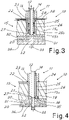
- Figure 4 shows in schematic form a variation of embodiment of the junction 10, in which the bottom of the seat 19 is formed with a sealing plug 35 inserted into the seat 16 and welded peripherally at 36 to the edge thereof opposite to the opening 17.
- the plug 35 to be welded to the end of the inner tube 12 before inserting the whole assembly inside the seat 16 and then welding the plug to the seat once the tube with the plug have been inserted in position inside the seat.
- a refractory layer 31 placed against the plate 15a and a tube plate 34a from which there projects a tube 33 for arrival of the fluid to be cooled, which is aligned with the passage 20 and the extension 32 inside the refractory layer, as described above for the embodiments shown in Figures 2 and 3 .
- FIG. 5 shows a possible variation of embodiment of the junction 10.
- a connecting element 53 is used instead of the layer of refractory material. This element 53 is arranged between the plate 15 (or 15b) and the tube 33 for arrival of the fluid to be cooled and connects the inside of the tube 33 to the passage 20 by means of an associated tubular inner passage 54.
- the element 53 has a form with a generally Y-shaped section so as to define a single-walled first end 55 and an opposite double-walled second end 56.
- the single-wall end is welded to the tube 33, while the outer part of the double-walled end 56 is welded to the plate 15.
- the plate 15 may have in the region of the weld a collar 57 around the passage 20 for facilitating butt-welding, to the plate, of the outer part of the element 53.
- the inner wall 58 of the tubular passage 54 has an end 50 close to the passage 20 which is free to define an annular space which allows the axial movement of this end 50 so as to compensate for the thermal expansions produced by the hot fluid which flows inside the passage 54.
- the inner wall 58 and the outer wall 60 of the double-walled part of the element 53 define a cavity which is filled with thermally insulating material 61 in order to reduce the passage of heat towards the outer wall 60.
- the thermally insulating material 61 may be preferably multi-layered with a variable conductivity (higher up towards the tube 33) and optionally in several circumferential sectors, namely with circumferential interruptions. This may avoid the formation of cracks.
- annular space at the end 59 of the inner wall 58 may be at least partially closed by a suitable seal 62 so as to reduce at least the possible infiltrations between the passage 54 and the cavity filled with insulating material 61.
- the seal 62 may be advantageously made with a split metal ring so as to allow its compression between the end 59 and the facing edge of the passage 20 when the end 59 moves close to this edge following thermal expansion of the wall 58.
- the end 59 and the facing edge of the passage 20 may be preferably made inclined with respect to the axial direction of the passage 54.
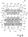
- Figures 6 shows schematically a cross-section of a heat exchanger with double-walled tubes, denoted generally by 40, provided according to the invention.
- This heat exchanger 40 comprises a bundle 41 of double-walled tubes, each formed by an inner tube 12 and an outer tube 13.
- the fluid to be cooled flows inside the inner tubes 12, while the cooling fluid flows inside the cavity 14 between the inner tube and outer tube.
- Manifolds 44 and 45 for the cooling fluid are also present at the two ends of the tube bundle and are connected to the cavities 14 of the tubes so as to allow the cooling fluid to flow inside said cavities.
- the fluid to be cooled may consist of the fumes output from an ethylene oven and the cooling fluid may be saturated water at a suitable pressure.
- FIG. 6 shows an exchanger with junctions 10 advantageously used on the inlet side of the exchanger (the bottom side in Figure 4 ) where the plate 15 (preferably divided into a first plate 15a and a second plate 15b) with the seats 16, the bottom 19 and the deflector 25 is therefore present.
- Figure 6 shows by way of example junctions of the type shown in Figure 2 , but it is understood that different connections according to the invention may also be used (for example those shown in Figures 3 or 4 ), as may now be easily imagined by the person skilled in the art.
- the end plates 15 of the junctions 10 of several adjacent double-walled tubes are made as a single piece.
- a single plate 15 extends between several tubes of the exchanger and has all the seats 16 for these tubes, as can be clearly seen in Figure 4 .
- This single plate (preferably the plate 15 or the plate 15a) may be advantageously forged as a single solid block, with the thicknesses already mentioned above.
- the second plate 15b, where present, may also be forged or obtained from a shaped metal sheet.
- the plates 15a and 15b may be connected together by means of welding, so as to ensure sealing of the cooling fluid with respect to the exterior.
- the single plate there may be present (typically only on the inlet side for the fluid to be cooled) the layer 31 of refractory material and optional tube plate 34 and the tubes 33 for arrival of the fluid to be cooled.
- the inner tubes thus receive directly the fluid to be cooled which passes through the extensions 32 present inside the refractory material.
- the plate 15 with the optional layer of refractory material and optional tube plate 34 thus forms a plate similar to the tube plate of an exchanger with tube bundle and container under pressure.
- the exchanger according to the invention may be easily connected to a chamber 46 for arrival of the fluid to be cooled through the tubes 33, which are for example connected to the outlet of an ethylene oven.
- the chamber 46 in reality does not exist because the hot fumes are conveyed to the outlet of the oven, already inside the tubes 33.
- the structure of the junction 10 may be advantageously replicated, preferably with some advantageous modifications.
- each tube (denoted generally by 110) is advantageously formed with an outlet end plate 115 in which a seat 116 for each tube is formed.
- the deflector 25 is preferably not present and the end of the outer tube 13 is peripherally fixed sealingly onto the outlet end plate 115 for connection to said seat 116 so as to define a cavity 126 which is an extension, inside the seat 116, of the cavity 14 of the double-walled tube around the outlet end of the inner tube 12.
- the inner tube 12 is connected to an outlet passage 120 on the bottom of the seat 116 so that the cooling fluid circulating in the seat surrounds the end of the inner tube inside the seat.
- the end of the outer tube is butt-welded onto the plate 115 so that the inner wall of the outer tube is situated substantially flush with the side wall of the seat 116 (thus formed with a diameter substantially the same as the internal diameter of the outer tube 13).
- the outlet end plate 115 there is at least one conduit 122 which emerges inside the cavity 126 for the passage of the cooling fluid which flows inside the cavity 14 of the double-walled tube 11.
- the passage for the cooling fluid 122 is advantageously formed close to the bottom of the seat 116 instead of being close to the opening of the seat which acts as an inlet for the double tubes, as it is instead for the inlet side of the exchanger.
- the top plate 115 or 115b will be comparable to the cold tube plate of a shell-and-tube exchanger and may be connected to a chamber 47 for collecting the fluid from the inner tubes 12 for evacuation thereof (for example via a conduit 52), as may be now easily imagined by the person skilled in the art.
- the plate 115 (or 115a) at the top end of the tubes may also have a thickness smaller than the thickness of the corresponding plate at the bottom end of the tubes, in order to prevent downward vertical movements of the cooling fluid which in this top zone may be for example a two-phase mixture of water+steam.
- the top plate (which is again advantageously forged and made of Mn-Mo-Ni material) may have a thickness equal to about a third of the thickness of the bottom plate.
- the top plate may have a thickness for example of about 250 mm.
- junctions on the cold side generally do not require a refractory layer as instead preferable for the junctions on the hot side.
- top junctions 110 may in any case be similar to that already described for the junction 10.
- FIG. 7 shows a variant of the junctions 10 on the hot side of an exchanger 40, again within the context of the present invention.
- the layer of refractory material has been replaced by the connecting elements 53, so as to obtain essentially junctions 10 of the type described with reference to Figure 5 .
- All the tubes 33 are thus connected to the respective passages 20 by means of the elements 53.
- the arrangement of the plurality of double tubes grouped together by a single plate may be different depending on the specific practical requirements, and may also use any of the junctions according to the invention.
- Figure 8 shows in schematic form a perspective view of a possible plate 15 advantageously formed by a forged thick plate 15a and by a thin plate 15b which also forms possible lateral fixing flanges 48.
- This plate has a plurality of seats 16 which emerge on the surface 24 of the plate in order to house corresponding double-walled plates and form an exchanger according to the invention.
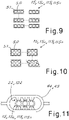
- the plate may be shaped in the manner of a parallelepiped with a rectangular base or have chamfered lateral corner edges (as shown in broken lines again in Figure 8 ) or may also have a rounded side wall so as to follow at least partially the progression of the side walls of the seats 16. For example, this is shown in Figures 9 and 10 .
- plates 15 or 15a
- a certain number N of adjacent aligned seats for example 3 seats
- modular structures of N double-walled tubes which may be arranged alongside each other in one or two directions, as shown schematically for example in Figure 9 , in order to form exchangers with any number of double tubes.
- plates 15 or 15a
- M rows for example two rows
- N adjacent aligned seats for example 3 seats
- the plate 15 or 15a made as a single piece for several tubes may have a peripheral edge 51 which is varyingly shaped and which for example follows at least partially the progression of the side wall of the seats on the edges of the plate so as to obtain a suitable wall thickness of the seats, as can be seen in Figures 9 and 10 .
- the plates 15b may also be formed so as to follow at least approximately the contour of the plates 15a to which they are joined.
- These plates 15b may have peripherally lateral flanges (for example shown at the two ends and indicated by 48 in Figure 6 ) in order to bolt together sealingly the inlet of the exchanger, or of the modules which form it, to the chamber 46 for arrival of the fluid to be cooled.
- the top plate 15b may also comprise end lugs 49 for the welded connection of the chamber 47.
- the chamber 47 may be advantageously oval/ellipsoidal and may advantageously combine the cooled fluid output from all the inner tubes.
- the chamber may also be able to be inspected by means of a suitable closing cover 63, shown in broken lines in Figure 6 . This cover may be a flat ellipsoidal cover facing the outlet passages 120.
- the inlet conduits 22 (bottom side) and outlet conduits 122 (top side) for the cooling fluid may be connected to the respective manifolds 44 and 45 connected in turn to a known cooling fluid treatment and circulation circuit.
- the manifolds 44 and/or 45 may be for example made so as to comprise a distribution toroid which laterally surrounds at least some junctions and from which the conduits which emerge inside the cavities of the junctions extend.
- Figure 11 shows schematically a plan view of a plate of a three-tube module which has conduits for the cooling fluid which extend radially towards a toroidal manifold 44 or 45 which surrounds the module.
- the double tubes in the exchanger may also be arranged alongside each in several parallel planes, with the tubes in each plane which are staggered for example by half a step with respect to the tubes in the adjacent planes. This is shown schematically by way of example for the module at the bottom on the right in Figure 10 .
- the inlets for the cooling fluid are close to the top of the seat 16 of the tubes, as already described above, and are advantageously at least two in number for each double tube and, for example, are all connected for each module to a toroid supplied by the downward tube(s) from a known steam generator (not shown).
- outlets for the water+steam mixture from the seats 116 in the top part of the exchanger are multiple, are as close as possible to the top of the seat and may also be as numerous as possible around the circumference of each double-walled tube. All the outlets may be connected to the toroid 45 which in turn supplies one or more riser tubes connected to the steam generator (not shown).
- the inlet manifold 44 may have for example two radially opposite inlets for each double-walled tube (as shown by means of short-dash lines in Figure 11 ), while the outlet manifold 45 may have for example four outlets for each double-walled tube (as shown by means of long-dash lines in Figure 11 ).
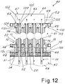
- Figure 12 shows a constructional variant of an exchanger according to the invention which uses junctions with sealing plugs similar to those schematically shown in Figure 4 .
- the exchanger 40 comprises respective sealing plugs 135 and 136.
- the plug 135 is welded in position on the plate 115a, while the plug 136 is welded in position on the plate 15a. In this way the plates 115b and 15b are not required.
- the flanges 48 may be made for example in the form a surrounding rim welded to the plate 15a.
- the sealing plug at one end has a diameter the same as the diameter of the holes in the plate 15a and advantageously at the other end the sealing plug (top plug 135 in the figure) has a diameter which is substantially the same as the internal diameter of the outer tube.
- the sealing plugs may be welded onto the inner tubes before the inner tubes are inserted inside the outer tubes. It is thus possible first to fix the outer tubes between the respective plates and then insert the inner tubes (from the end with the smaller-diameter sealing plug) and weld them in position. This simplifies greatly the assembly of the exchanger and reduces the time needed for construction thereof.
- junction and the exchanger proposed solve for example the physiological problems associated with the quenching of hot fumes in heat exchangers of the type comprising banks of double tubes for use, for example, in ethylene ovens.
- the exchanger according to the invention may also replace advantageously shell-and-tube exchangers.
- the plate 15-115 With the special part formed by the plate 15-115 (15a-115a) preferably made of highly yielding material (Mn-Mo-Ni steel) and with a high linear expansion coefficient compared to conventional carbon steels it is possible to compensate also for the difference in temperature which exists physiologically between the inner tube and outer tube, reducing the mechanical stresses in the structure.
- highly yielding material Mn-Mo-Ni steel
- the special geometry which may be realized according to the invention allows the creation for each module of a pseudo-linear exchanger; such that the bottom part and the top part which form the barrier element between the hot fumes and the cooling fluid may be comparable to a pseudo flat tube plate which may also have a flanged extension.
- the pseudo bottom plate 15b may be preferably made of Inconel.
- the plate 34 and/or the tube 33 may be made of Incoloy.
- the pseudo top plate depending on the output temperatures of the fumes, may be made of low alloyed or stainless steel.
- the plates 15 or 15a and/or the plate 115 or 115a are advantageously made of material which is highly yielding and has a specific elongation compared to the tubes in order to lessen the compressive stressing of the tubes.
- the hot fumes output may be conveyed into an ellipsoidal chamber, in view of the low pressure of the cracking fumes, where the outlets of the inner tubes of each module may be connected together.
- the ellipsoidal chamber may for example in turn terminate in a flanged elliptical cover which may be easily removed and which allows easy inspection/maintenance/cleaning.
- Entry of the hot fumes may in turn occur into a chamber which is common to all the inner tubes of each module and which is flanged together with the pseudo bottom tube plate and a plate for example made of Incoloy and in turn welded to the oven outlet openings.
- This chamber may be suitably protected by refractory material with pre-shaped blocks of material able to withstand erosion/abrasion of the hot fumes.
- the above description of an embodiment applying the innovative principles of the present invention is provided by way of example of these innovative principles and must therefore not be regarded as limiting the scope of the rights claimed herein.
- the proportions of the various parts of the junction and the exchanger may vary from that shown in the drawings so as to be adapted to specific requirements, as may be easily imagined by the person skilled in the art.
- the number of tubes and their arrangement may vary depending on the practical implementation and the specific requirements.
- the various junctions described and the assembly solutions may be combined in different ways with each other and, where necessary also with the elements 53 in an exchanger according to the invention.
Landscapes
- Engineering & Computer Science (AREA)
- Physics & Mathematics (AREA)
- Thermal Sciences (AREA)
- Mechanical Engineering (AREA)
- General Engineering & Computer Science (AREA)
- Heat-Exchange Devices With Radiators And Conduit Assemblies (AREA)
Description
- The present invention relates to junctions for double-walled tubes in heat exchangers. Moreover, the present invention relates to exchangers provided with such junctions.
- In the sector of exchangers, exchangers of the type with double-walled tubes are known. These exchangers comprise a plurality of double-walled tubes each formed by an inner tube inside which the fluid to be cooled flows and an outer tube coaxial with the inner tube so as form a cavity inside which the cooling fluid flows. Especially in the case of exchangers with double-walled tubes operating at high temperatures (even higher than 650°C and generally in the region of 900°C), such as the exchangers intended to perform quenching of the hot fumes output from ethylene production ovens, the junction at the ends of the tubes for connecting each inner tube and the cavity between the tubes to the respective fluids is particularly critical. In fact, in the connection zone, the temperature of the connected tubes varies significantly within the space of a few centimetres.
- As regards the critical part, namely the end connections of the double-walled tubes, the double-walled tube exchangers may be basically divided up into two main categories.
- In the first category each double-walled tube has a special Y-shaped piece, namely a connecting piece having a double-walled tubular end and an opposite single-walled end for connecting one of the N linear outputs of the radiant element with the inner tube and for forming at the same time an annular chamber at the end of the cavity between outer tube and inner tube, with this chamber which is connected to the cooling fluid flow (for example a water+steam mixture).
- This type of junction has the drawback that the temperature gradient in the Y-junction is extremely high since the temperature varies within a few millimetres from the value of the hot fumes (for example at about 900°C) to the value of the cooling fluid (usually boiling water corresponding to the working pressure) with a temperature range which is certainly critical for the metals used and which results for example in ageing of the material.
- Moreover, the zone of the connecting welds may be difficult to cool, even if two cooling fluid inlets are present; and this also worsens the thermal stressing of the junction (local increases in temperature).
- In an attempt to limit the drawbacks of this first type of connection, in the second category of double-walled exchangers a sleeve is added inside the part of the special single-walled Y-shaped piece. This sleeve has a free end so as to be able to expand axially, being exposed on the inner side to the full temperature of the incoming hot fumes (for example at 900°C) and an opposite end welded onto an extension of the single-walled Y-shaped piece. The annular ring thus formed between sleeve and Y-shaped piece is filled with heat insulation, for example formed by multiple layers of refractory material of varied conductivity (in order to ensure a small temperature gradient in the conical part of the Y-shaped piece), or by diluting steam which is at a slightly higher pressure than the hot fumes (said steam forms a near-stagnant insulating cavity, part thereof being mixed with the hot fumes escaping above the sleeve). The advantage of this solution with insulation consists in the reduced thermal stresses in the outer cylinder of the Y-shaped piece (lower temperature gradient), which is protected by the insulation layer. Despite its greater complexity, this solution is therefore hitherto the one which is most widely used.
- It has, however, the drawback of potential infiltration of particulate matter (coke) due to the sleeve which is not sealed off from the hot fluid flow. Such infiltration may in turn result in distortion of the sleeve and in some cases cause cracking thereof. Thus this solution also does not deal with the existing problems.
- Furthermore, in all the design solutions present on the market the design of the inlet for the cooling fluid (for example saturated water) into the cavity of the double-walled tubes and also the design of the outlet for said fluid at the opposite end of the exchanger (where generally the cooling fluid is a balanced mixture of liquid and steam) remains a critical aspect.
- Essentially the known inlet systems, but also outlet systems (for easier comprehension reference will be made below to inlet systems) may be summarised as follows:
- an oval chamber for distribution of the cooling fluid, with one or two linear-end inlets, which supplies in series/sequence the annular chamber situated between the outer tube and the inner tube of each double-walled tube;
- one or two cooling fluid distribution nozzles which supply the annular chamber situated between the outer tube and the inner tube of each double-walled tube; said nozzles being able to be located flush with the zone of the Y-shaped union which connects the inner tube and the outer tube or at a greater height with respect to the bottom of the water chamber (but always at a height of less than 200 mm), with an internal conveyor which forces a vertical flow of the fluid (usually near-saturated water) before the bottom of the annular chamber is reached. The inlet nozzles may then be perfectly aligned with the axis of the tubes (namely the axis of the nozzle(s) intersects the longitudinal axis of the inner tube and the outer tube) or may be eccentric so as to create a rising helical movement.
- In all the solutions, however, from a fluid-dynamic point of view, the circular symmetry (namely the same flow in each angular portion) is not guaranteed and physiologically zones with a depressed/stagnant flow are present, these becoming even more critical as mentioned in the type of union, without thermal insulation, of the Y-shaped piece.
- A completely different type of exchanger consists of shell-and-tube exchangers, which are often referred to as exchangers of the TLE type (Transfer Line Exchangers), while the tube exchangers with double-walled tubes are often called exchangers of the PQE type (Primary Quench Exchangers) or LQE type (Linear Quench Exchangers).
- Expressed very simply, where the outflow from the radiant ovens occurs via a single opening, the installation of TLEs with tube bundle is required, while PQEs with double-walled tubes are used where the outflow from the ovens occurs via multiple openings which are spaced close together in one or more staggered rows.
- The decision as to the type of oven is the responsibility of the engineering company specialized in oven design; the supplier of the downstream apparatus (i.e. the TLEs or PQEs) is therefore required to install sometimes TLEs and sometimes PQEs.
- The two types of exchangers, while providing the same service (rapid quenching of hot fumes and steam production) are however very different from each other. The PQEs tend to be much longer than the TLEs and have much bigger through-flow/outflow cross-sections for the hot fumes; such that, for the same length, the dwell times of the fumes is much shorter in the PQEs than in the TLEs. This reduces the soiling due to the formation of coke and allows much longer operating cycles in ovens equipped with PQEs rather than with TLEs.
- It would therefore on occasions be preferable to use PQEs, but this is incompatible with the connection needs of the exchanger, which are instead satisfied by the TLEs.
- However, both in PQEs and in TLEs there exist among other things the problems which are summarised below:
- high erosion caused by the gas due to the conveying of solid particulate matter at high linear speeds (> 100 m/s);
- high corrosion on the water side in the event of sedimentation of deposits and/or stagnating/dead zones given that the secondary circuit is a natural radiator (secondary circuit for near-saturated medium-high pressure water);
- risk of local overheating in the aforementioned depressed flow zones owing to the collapse of the boiling coefficient of the saturated water;
- concentration of bubbles in the top part of the exchanger with potential further stagnation/blanketing and associated overheating.
- The main object of the present invention is to overcome the problems of the prior art by providing junctions with an improved structure for joining the double-walled tubes in heat exchangers. Furthermore, a further object is to provide heat exchangers with such junctions. In view of these objects the idea which has occurred is to provide, according to the invention, a heat exchanger according to claim 1.
- An end junction in the heat exchanger comprises a double-walled tube comprising an inner tube in which a fluid to be cooled flows and an outer tube which defines with the inner tube a cavity in the double-walled tube in which a cooling fluid flow: wherein at one end of the double-walled tube an end plate in which there is a seat has an opening on one face of the end plate, an end portion of the end of the inner tube being housed coaxially in the seat through said opening, and with the corresponding outer tube which is peripherally fixed sealingly around said opening, a deflector extending the inner wall of the outer tube inside the seat so as to define a toroidal cavity between the deflector and a side wall of the seat, the seat being closed by a bottom which is opposite to said opening and which has a passage connected sealingly to the end of the inner tube in the seat for the transit of the fluid to be cooled, a radial space being present near the said bottom between the toroidal cavity and the inner cavity of the double-walled tube, and the end plate having at least one conduit which emerges inside the toroidal cavity for the inflow or the outflow of the cooling fluid.
- Still in view of these objects, another idea which has occurred is to provide, according to the invention, a heat exchanger comprising a bundle of double-walled tubes each formed by an inner tube and by an outer tube, with flowing of fluid to be cooled inside the inner tube and flowing of cooling fluid inside a cavity between inner tube and outer tube, with an inlet for the fluid to be cooled at one end of the bundle of double-walled tubes and an outlet for the fluid to be cooled which is cooled at the other end of the bundle of double-walled tubes, and with manifolds for the cooling fluid at the two ends of the double-walled tube bundle, connected to the said cavities between inner tubes and outer tubes, characterized in that at least at one end of the tube bundle the connection between each tube of the bundle, corresponding inlets or outlets for the fluid to be cooled and manifolds for the cooling fluid is realized with a junction of the aforementioned type.
- In order to illustrate more clearly the innovative principles of the present invention and its advantages compared to the prior art, an example of embodiment applying these principles will be described below with the aid of the accompanying drawings. In the drawings:
-
Figure 1 shows a partially sectioned, exploded, schematic side view of a first embodiment of a junction according to the invention; -
Figure 2 shows a schematic assembled view of the junction according toFigure 1 ; -
Figures 3, 4 and5 show partially sectioned, schematic side views of a second, third and fourth embodiment, respectively, of a junction according to the invention; -
Figure 6 shows a partially sectioned, partial, schematic side view of an exchanger according to the invention; -
Figure 7 shows a partially sectioned, partial, schematic side view of a possible variation of embodiment of the exchanger according toFigure 5 ; -
Figure 8 shows a schematic perspective view of a possible plate of the junction according to the invention; -
Figures 9 and 10 show partial schematic plan views of possible connection plates present at the end of tubes of an exchanger according to the invention; -
Figure 11 shows a partial schematic plan view of possible connections for the cooling fluid at the end of tubes of an exchanger according to the invention; -
Figure 12 shows a view similar to that ofFigure 6 of a further constructional variant of an exchanger according to the invention. - With reference to the figures,
Figures 1 and 2 show, respectively, an exploded view and assembled view of an end junction, denoted overall by 10, of a double-walled tube (or double tube) 11 in a heat exchanger. - The double-
walled tube 11 comprises aninner tube 12 inside which a fluid to be cooled flows and anouter tube 13 which is coaxial with the inner tube and defines with the inner tube acavity 14 inside which the cooling fluid (for example water) of the exchanger flows. - The junction comprises an
end plate 15 in which there is aseat 16 which has an opening 17 on oneface 24 of the plate directed towards the double-walled tube. - The
seat 16 has a side wall 18 (which may advantageously have a cylindrical form coaxial with the double tube 11) and abottom 19 opposite to theopening 17 and therefore facing the end of thedouble tube 11. - The
bottom 19 has apassage 20 which is coaxial with the tube and which is sealingly connected to the end of theinner tube 12 for the transit of the fluid to be cooled. Advantageously the connection is obtained by means of welding. Preferably, thepassage 20 has acollar 21 which projects into theseat 16 so as to be coaxial with theinner tube 12 and allow butt-welding of the end of the inner tube. Said welding may be of the IBW type, i.e. an internal bore welding, as may be easily imagined by the person skilled in the art. - The
end plate 15 also has at least oneconduit 22 which emerges in theside wall 18 for the inflow or outflow of the cooling fluid, as will be explained below. This conduit emerges inside theseat 16 in a position advantageously close to theopening 17 so as to obtain a circulation of the cooling fluid over the entire height of the seat, as will be explained below. As can be clearly seen inFigure 2 , theopening 17 of theseat 16 houses coaxially inside the seat an end portion of the end of theinner tube 12 which extends preferably by a certain amount beyond the end of the outer tube. The correspondingouter tube 13 is peripherally connected sealingly around theopening 17. Advantageously, theopening 17 follows the perimeter of theouter tube 13 and has a diameter which is smaller than the outer diameter of the outer tube so as to allow the formation of aperipheral weld 23. - Advantageously, the diameter of the
opening 17 has a value between the outer diameter and the inner diameter of theouter tube 13. In this way the inner wall of the outer tube projects into theopening 17 and far from theside wall 18 of the seat. - A
deflector 25 extends the inner wall of theouter tube 13 inside theseat 16 so as to define a substantiallytoroidal cavity 26 between thedeflector 25 and theside wall 18 of the seat. Thecirculation conduit 22 thus leads into this cavity. Advantageously theconduit 22 emerges inside the toroidal cavity in a direction radial thereto. - As will be explained below, the
conduits 22 which emerge inside the toroidal cavity may be more than one and are arranged preferably at intervals around the toroidal cavity so as to ensure a sufficiently uniform distribution of the cooling fluid. - A
radial space 27 is also present close to the bottom 19 between thecavity 26 and thecavity 14 inside the double-walled tube and connects the two cavities. This radial space may be simply obtained by designing the deflector with dimensions so as to have the end edge which remains far from the bottom 19. Advantageously the bottom 19 may also be shaped so as to connect with a curved section theside wall 18 of the seat and the wall of the inner tube welded to thepassage 20, as can be seen for example in the figures. - The distance of the end of the conveyor from the bottom of the seat may be for example of the order of centimetres, but sufficient to allow a circular symmetrical inflow of the cooling fluid into the annular portion between the inner tube and the inner diameter of the conveyor. For example, this distance may be about 5-20 mm and is preferably about 10-15 mm.
- As can be seen in
Figures 1 and 2 , thedeflector 25 may be made with a final portion of theouter tube 13 having a reduced external diameter so as to enter into the seat through theopening 17 and face theside wall 18 of the seat. - Alternatively, the deflector may be made with a cylindrical collar 25b which projects into the seat from the
opening 17. In this case, as can be seen for example inFigure 3 , the collar 25b may project into the seat from a cover 28 placed on top of theface 24 of the plate. The cover 28 may also advantageously comprise a collar 29 which projects with respect to the plane of the cover 28 so as to allow butt-welding of theouter tube 13. The cover 28 may have a very small thickness compared to theplate 15. For example, the cover 28 may have a thickness which is between 1/80th and 1/60th of theplate 15. In particular, the cover 28 may have a thickness in the region of 10-15 mm. - Advantageously, the radial width of the
cavity 26 is such that, with respect to the radial amplitude of thecavity 14 inside the double tube, a high falling speed suitable for ensuring a uniform flow in every angular position is created inside the chamber for downward vertical distribution of the cooling fluid. For example, the amplitude of thecavity 26 may be substantially the same as, if not smaller than the amplitude of thecavity 14. - The
deflector 25 may have a smaller thickness (for example about 1.5 - 2 mm), not being subject to particular stresses since it is of the differential pressure type. - As can be clearly seen in the figures, the
end plate 15 may be advantageously formed by afirst plate 15a and by asecond plate 15b which are coupled together. The twoplates side wall 18 of theseat 16 is situated substantially in the first plate and the bottom 19 of the seat is situated in the second plate. This simplifies even more the formation of the seat, which is formed for example by a simple cylindrical through-hole, and of the bottom, which may be shaped. - The plate 15 (or the
first plate 15a) may have advantageously a thickness at least equal to 500 mm (at least when used on the inlet side for the fluid to be cooled) so as to form a suitable height of the seat and make the assembly very robust. Preferably, the plate 15 (or 15a) on the inlet side of an exchanger may have a height of at least 750 mm. Theplate 15b, if present, may instead be much thinner. For example it may be between 1/80th and 1/60th of theplate 15a. In particular, it may be for example 10-15 mm thick. - The plate 15 (or 15a) may be advantageously a solid plate.
- The large thickness of the
plate 15 advantageously strengthens the connections at the ends of the tubes which are subject to varying degrees of elongation due to thermal expansion. - The two plates may be coupled together using various known methods. For example they may be welded together.
- The plate 15 (and in the case of two
plates plate 15a which forms theface 24 towards the tubes) may be advantageously made as a forged piece. Using a forged piece is advantageous because it has a load limit higher than that of the tubes. Moreover, preferably said plate is made of highly yielding steel (Mn-Mo-Ni) - The use of a highly yielding material such as Mn-Mo-Ni is also advantageous because it has a greater elongation (for the same operating temperature) than carbon steel, from which the outer tubes may be advantageously made. Since the inner tubes are hotter than the outer tubes, it follows that by making this part using high-quality metals, it is possible to reduce/lessen the (compressive) axial force of the inner tubes.
- As can be seen again in
Figures 2 and3 , thepassage 20 opens out advantageously in aface 30 of theend plate 15 which is opposite to the double-walled tube. The two faces 24 and 30 may be parallel to each other and extend transversely with respect to the axis of the double-walled tubes. A layer ofrefractory material 31 may be present on theface 30. This layer of refractory material is crossed by anextension 32 of thepassage 20 so as to allow the transit of the fluid to be cooled through thelayer 31. - A
tube 33 may convey the fluid to be cooled to thepassage 20/32. - The
passage 20, theextension 32 and thetube 33, if present, are all advantageously coaxial with theinner tube 12 so as to create a minimum obstacle to the passage of the fluid flow inside theinner tube 12. - The
tube 33 may also project from atube plate 34 applied onto the free face of the refractory material. In this way, the heat at the outer end of thetube 33 is at least partially conveyed to theplate 34 which is thermally insulated from theface 30 of theplate 15 owing to the layer ofrefractory material 31. -
Figure 4 shows in schematic form a variation of embodiment of thejunction 10, in which the bottom of theseat 19 is formed with a sealingplug 35 inserted into theseat 16 and welded peripherally at 36 to the edge thereof opposite to theopening 17. This allows for example advantageously theplug 35 to be welded to the end of theinner tube 12 before inserting the whole assembly inside theseat 16 and then welding the plug to the seat once the tube with the plug have been inserted in position inside the seat. In this embodiment also, there may be provided arefractory layer 31 placed against theplate 15a and a tube plate 34a from which there projects atube 33 for arrival of the fluid to be cooled, which is aligned with thepassage 20 and theextension 32 inside the refractory layer, as described above for the embodiments shown inFigures 2 and3 . -
Figure 5 shows a possible variation of embodiment of thejunction 10. In this variant, a connectingelement 53 is used instead of the layer of refractory material. Thiselement 53 is arranged between the plate 15 (or 15b) and thetube 33 for arrival of the fluid to be cooled and connects the inside of thetube 33 to thepassage 20 by means of an associated tubularinner passage 54. - As can be clearly seen in
Figure 5 , theelement 53 has a form with a generally Y-shaped section so as to define a single-walledfirst end 55 and an opposite double-walledsecond end 56. The single-wall end is welded to thetube 33, while the outer part of the double-walled end 56 is welded to theplate 15. Theplate 15 may have in the region of the weld acollar 57 around thepassage 20 for facilitating butt-welding, to the plate, of the outer part of theelement 53. - The
inner wall 58 of thetubular passage 54 has anend 50 close to thepassage 20 which is free to define an annular space which allows the axial movement of thisend 50 so as to compensate for the thermal expansions produced by the hot fluid which flows inside thepassage 54. Theinner wall 58 and theouter wall 60 of the double-walled part of theelement 53 define a cavity which is filled with thermally insulatingmaterial 61 in order to reduce the passage of heat towards theouter wall 60. The thermally insulatingmaterial 61 may be preferably multi-layered with a variable conductivity (higher up towards the tube 33) and optionally in several circumferential sectors, namely with circumferential interruptions. This may avoid the formation of cracks. - Advantageously the annular space at the
end 59 of theinner wall 58 may be at least partially closed by asuitable seal 62 so as to reduce at least the possible infiltrations between thepassage 54 and the cavity filled with insulatingmaterial 61. - The
seal 62 may be advantageously made with a split metal ring so as to allow its compression between theend 59 and the facing edge of thepassage 20 when theend 59 moves close to this edge following thermal expansion of thewall 58. In order to facilitate this movement, theend 59 and the facing edge of thepassage 20 may be preferably made inclined with respect to the axial direction of thepassage 54. - Although described for sake of simplicity in relation to the connection shown in
Figure 2 , it is understood that theelement 53 may be obviously used also in the other embodiments of a connection according to the present invention. -
Figures 6 shows schematically a cross-section of a heat exchanger with double-walled tubes, denoted generally by 40, provided according to the invention. - This
heat exchanger 40 comprises abundle 41 of double-walled tubes, each formed by aninner tube 12 and anouter tube 13. The fluid to be cooled flows inside theinner tubes 12, while the cooling fluid flows inside thecavity 14 between the inner tube and outer tube. - The inflow of the fluid to be cooled occurs at one
end 42 of the tube bundle and the outflow of the cooled fluid occurs at theother end 43 of the tube bundle.Manifolds cavities 14 of the tubes so as to allow the cooling fluid to flow inside said cavities. - For simpler description reference will be made to an exchanger with inflow of the fluid to be cooled from the bottom and a flow of cooling fluid which is co-current, namely also from the bottom upwards. This is the configuration which covers almost all the existing plants. For the person skilled in the art it however may be easily understood that the exchanger may be designed also with different configurations (for example, fluid to be cooled from the top and cooling fluid from the bottom in a counter-current arrangement).
- In particular, the fluid to be cooled may consist of the fumes output from an ethylene oven and the cooling fluid may be saturated water at a suitable pressure.
- At at least one end of the tube bundle, the connection between each tube of the bundle, the corresponding inlets or outlets for the fluid to be cooled and the manifolds for the cooling fluid is performed with a
junction 10 according to the invention. For example,Figure 6 shows an exchanger withjunctions 10 advantageously used on the inlet side of the exchanger (the bottom side inFigure 4 ) where the plate 15 (preferably divided into afirst plate 15a and asecond plate 15b) with theseats 16, the bottom 19 and thedeflector 25 is therefore present. For simpler illustration,Figure 6 shows by way of example junctions of the type shown inFigure 2 , but it is understood that different connections according to the invention may also be used (for example those shown inFigures 3 or 4 ), as may now be easily imagined by the person skilled in the art. - Preferably, the
end plates 15 of thejunctions 10 of several adjacent double-walled tubes (or, if present, the first and/or the second plate of the end plates of thejunction 10 of several adjacent double-walled tubes) are made as a single piece. - In other words a single plate 15 (or 15a and/or 15b) extends between several tubes of the exchanger and has all the
seats 16 for these tubes, as can be clearly seen inFigure 4 . - This single plate (preferably the
plate 15 or theplate 15a) may be advantageously forged as a single solid block, with the thicknesses already mentioned above. Thesecond plate 15b, where present, may also be forged or obtained from a shaped metal sheet. - The
plates - Underneath the single plate there may be present (typically only on the inlet side for the fluid to be cooled) the
layer 31 of refractory material andoptional tube plate 34 and thetubes 33 for arrival of the fluid to be cooled. The inner tubes thus receive directly the fluid to be cooled which passes through theextensions 32 present inside the refractory material. - The
plate 15 with the optional layer of refractory material andoptional tube plate 34 thus forms a plate similar to the tube plate of an exchanger with tube bundle and container under pressure. In this way, the exchanger according to the invention may be easily connected to achamber 46 for arrival of the fluid to be cooled through thetubes 33, which are for example connected to the outlet of an ethylene oven. - The
chamber 46 in reality does not exist because the hot fumes are conveyed to the outlet of the oven, already inside thetubes 33. - On the outlet side (top side in
Figure 6 ) of the exchanger according to the invention the structure of thejunction 10 may be advantageously replicated, preferably with some advantageous modifications. - For simpler illustration, elements of the outlet junction similar to those of the inlet junction are indicated in the figures by the same numbers, increased by 100.
- As can be seen in
Figure 6 , the top junction of each tube (denoted generally by 110) is advantageously formed with anoutlet end plate 115 in which aseat 116 for each tube is formed. Unlike theinlet junction 10, in theoutlet junction 110 thedeflector 25 is preferably not present and the end of theouter tube 13 is peripherally fixed sealingly onto theoutlet end plate 115 for connection to saidseat 116 so as to define acavity 126 which is an extension, inside theseat 116, of thecavity 14 of the double-walled tube around the outlet end of theinner tube 12. Theinner tube 12 is connected to anoutlet passage 120 on the bottom of theseat 116 so that the cooling fluid circulating in the seat surrounds the end of the inner tube inside the seat. - Advantageously, the end of the outer tube is butt-welded onto the
plate 115 so that the inner wall of the outer tube is situated substantially flush with the side wall of the seat 116 (thus formed with a diameter substantially the same as the internal diameter of the outer tube 13). - In the
outlet end plate 115 there is at least oneconduit 122 which emerges inside thecavity 126 for the passage of the cooling fluid which flows inside thecavity 14 of the double-walled tube 11. The passage for the coolingfluid 122 is advantageously formed close to the bottom of theseat 116 instead of being close to the opening of the seat which acts as an inlet for the double tubes, as it is instead for the inlet side of the exchanger. - This makes it possible to avoid downward vertical movements of the cooling fluid inside the seat and prevents any vapour bubbles, which could form at the top end of the exchanger, from hindering the outflow of the cooling fluid through the
passages 122. - The
top plate chamber 47 for collecting the fluid from theinner tubes 12 for evacuation thereof (for example via a conduit 52), as may be now easily imagined by the person skilled in the art. - The plate 115 (or 115a) at the top end of the tubes may also have a thickness smaller than the thickness of the corresponding plate at the bottom end of the tubes, in order to prevent downward vertical movements of the cooling fluid which in this top zone may be for example a two-phase mixture of water+steam.
- For example, the top plate (which is again advantageously forged and made of Mn-Mo-Ni material) may have a thickness equal to about a third of the thickness of the bottom plate. In particular, the top plate may have a thickness for example of about 250 mm.
- Moreover, the junctions on the cold side generally do not require a refractory layer as instead preferable for the junctions on the hot side.
- Apart from the modifications mentioned here, the
top junctions 110 may in any case be similar to that already described for thejunction 10. -
Figure 7 shows a variant of thejunctions 10 on the hot side of anexchanger 40, again within the context of the present invention. In this variant the layer of refractory material has been replaced by the connectingelements 53, so as to obtain essentiallyjunctions 10 of the type described with reference toFigure 5 . All thetubes 33 are thus connected to therespective passages 20 by means of theelements 53. - In an exchanger according to the invention, the arrangement of the plurality of double tubes grouped together by a single plate may be different depending on the specific practical requirements, and may also use any of the junctions according to the invention.
-
Figure 8 shows in schematic form a perspective view of apossible plate 15 advantageously formed by a forgedthick plate 15a and by athin plate 15b which also forms possiblelateral fixing flanges 48. This plate has a plurality ofseats 16 which emerge on thesurface 24 of the plate in order to house corresponding double-walled plates and form an exchanger according to the invention. - The plate may be shaped in the manner of a parallelepiped with a rectangular base or have chamfered lateral corner edges (as shown in broken lines again in
Figure 8 ) or may also have a rounded side wall so as to follow at least partially the progression of the side walls of theseats 16. For example, this is shown inFigures 9 and 10 . - It is possible to consider forming plates 15 (or 15a) with a certain number N of adjacent aligned seats (for example 3 seats) so as to thus form modular structures of N double-walled tubes which may be arranged alongside each other in one or two directions, as shown schematically for example in
Figure 9 , in order to form exchangers with any number of double tubes. - It is also possible to consider forming plates 15 (or 15a) with M rows (for example two rows) of N adjacent aligned seats (for example 3 seats) so as to thus form modular structures of NxM tubes which may be arranged alongside each other in one or two directions, as shown schematically for example in
Figure 10 . - In any case, as mentioned above, the
plate peripheral edge 51 which is varyingly shaped and which for example follows at least partially the progression of the side wall of the seats on the edges of the plate so as to obtain a suitable wall thickness of the seats, as can be seen inFigures 9 and 10 . - It is thus possible to obtain plates with
angled points 50 which allow all the double tubes to be joined together and provide the system with a rigid structure. - The
plates 15b, where present, may also be formed so as to follow at least approximately the contour of theplates 15a to which they are joined. Theseplates 15b may have peripherally lateral flanges (for example shown at the two ends and indicated by 48 inFigure 6 ) in order to bolt together sealingly the inlet of the exchanger, or of the modules which form it, to thechamber 46 for arrival of the fluid to be cooled. - The
top plate 15b may also comprise end lugs 49 for the welded connection of thechamber 47. Thechamber 47 may be advantageously oval/ellipsoidal and may advantageously combine the cooled fluid output from all the inner tubes. The chamber may also be able to be inspected by means of asuitable closing cover 63, shown in broken lines inFigure 6 . This cover may be a flat ellipsoidal cover facing theoutlet passages 120. - The inlet conduits 22 (bottom side) and outlet conduits 122 (top side) for the cooling fluid may be connected to the
respective manifolds manifolds 44 and/or 45 may be for example made so as to comprise a distribution toroid which laterally surrounds at least some junctions and from which the conduits which emerge inside the cavities of the junctions extend. - For example,
Figure 11 shows schematically a plan view of a plate of a three-tube module which has conduits for the cooling fluid which extend radially towards atoroidal manifold - If desired, the double tubes in the exchanger may also be arranged alongside each in several parallel planes, with the tubes in each plane which are staggered for example by half a step with respect to the tubes in the adjacent planes. This is shown schematically by way of example for the module at the bottom on the right in
Figure 10 . - Preferably, the inlets for the cooling fluid, in particular water, are close to the top of the
seat 16 of the tubes, as already described above, and are advantageously at least two in number for each double tube and, for example, are all connected for each module to a toroid supplied by the downward tube(s) from a known steam generator (not shown). - The outlets for the water+steam mixture from the
seats 116 in the top part of the exchanger are multiple, are as close as possible to the top of the seat and may also be as numerous as possible around the circumference of each double-walled tube. All the outlets may be connected to thetoroid 45 which in turn supplies one or more riser tubes connected to the steam generator (not shown). - Preferably, the
inlet manifold 44 may have for example two radially opposite inlets for each double-walled tube (as shown by means of short-dash lines inFigure 11 ), while theoutlet manifold 45 may have for example four outlets for each double-walled tube (as shown by means of long-dash lines inFigure 11 ). -
Figure 12 shows a constructional variant of an exchanger according to the invention which uses junctions with sealing plugs similar to those schematically shown inFigure 4 . - Elements similar to those shown in
Figure 6 are indicated inFigure 12 using the same numbers, unless otherwise indicated, and are not further described in detail below. - At the two ends of the inner tubes the
exchanger 40 according toFigure 12 comprises respective sealing plugs 135 and 136. Theplug 135 is welded in position on theplate 115a, while theplug 136 is welded in position on theplate 15a. In this way theplates flanges 48 may be made for example in the form a surrounding rim welded to theplate 15a. - Advantageously, the sealing plug at one end (in
Figure 12 the bottom plug 136) has a diameter the same as the diameter of the holes in theplate 15a and advantageously at the other end the sealing plug (top plug 135 in the figure) has a diameter which is substantially the same as the internal diameter of the outer tube. In this way, the sealing plugs may be welded onto the inner tubes before the inner tubes are inserted inside the outer tubes. It is thus possible first to fix the outer tubes between the respective plates and then insert the inner tubes (from the end with the smaller-diameter sealing plug) and weld them in position. This simplifies greatly the assembly of the exchanger and reduces the time needed for construction thereof. - At this point it is clear how the predefined objects have been achieved.
- The junction and the exchanger proposed solve for example the physiological problems associated with the quenching of hot fumes in heat exchangers of the type comprising banks of double tubes for use, for example, in ethylene ovens.
- Moreover, as a result of the junction according to the invention it is possible to obtain a cooling fluid flow with a perfect circular symmetry.
- The exchanger according to the invention may also replace advantageously shell-and-tube exchangers.
- With the special part formed by the plate 15-115 (15a-115a) preferably made of highly yielding material (Mn-Mo-Ni steel) and with a high linear expansion coefficient compared to conventional carbon steels it is possible to compensate also for the difference in temperature which exists physiologically between the inner tube and outer tube, reducing the mechanical stresses in the structure.
- Use of the plates 15-115, 15a-115a is able to reduce greatly the compressive axial stress which is exerted on each inner tube.
- Moreover, owing to the invention, it is possible to group together the single double-walled tubes into modules so as to create a pseudo-linear shell exchanger (the bottom and top shells being the
plates - The special geometry which may be realized according to the invention allows the creation for each module of a pseudo-linear exchanger; such that the bottom part and the top part which form the barrier element between the hot fumes and the cooling fluid may be comparable to a pseudo flat tube plate which may also have a flanged extension. The
pseudo bottom plate 15b may be preferably made of Inconel. Theplate 34 and/or thetube 33 may be made of Incoloy. The pseudo top plate, depending on the output temperatures of the fumes, may be made of low alloyed or stainless steel. - The
plates plate - As described above, the hot fumes output may be conveyed into an ellipsoidal chamber, in view of the low pressure of the cracking fumes, where the outlets of the inner tubes of each module may be connected together. The ellipsoidal chamber may for example in turn terminate in a flanged elliptical cover which may be easily removed and which allows easy inspection/maintenance/cleaning.
- Entry of the hot fumes may in turn occur into a chamber which is common to all the inner tubes of each module and which is flanged together with the pseudo bottom tube plate and a plate for example made of Incoloy and in turn welded to the oven outlet openings. This chamber may be suitably protected by refractory material with pre-shaped blocks of material able to withstand erosion/abrasion of the hot fumes.
- Obviously, the above description of an embodiment applying the innovative principles of the present invention is provided by way of example of these innovative principles and must therefore not be regarded as limiting the scope of the rights claimed herein. For example, the proportions of the various parts of the junction and the exchanger may vary from that shown in the drawings so as to be adapted to specific requirements, as may be easily imagined by the person skilled in the art. Also the number of tubes and their arrangement may vary depending on the practical implementation and the specific requirements. As mentioned above, the various junctions described and the assembly solutions may be combined in different ways with each other and, where necessary also with the
elements 53 in an exchanger according to the invention.
Claims (22)
- Heat exchanger having an end junction (10) comprising a double-walled tube (11) and an end plate , the double-walled tube (11) comprising an inner tube (12) in which a fluid to be cooled flows and an outer tube (13) which defines with the inner tube a cavity (14) inside the double-walled tube (11) in which a cooling fluid flows, wherein atone end of the double-walled tube (11) the end plate (15) in which there is a seat (16) has an opening (17) on a face (24) of the end plate, an end portion of the end of the inner tube (12) being coaxially housed in the seat (16) through said opening (17), characterised by the corresponding outer tube (13) being peripherally fixed sealingly around said opening (17),a deflector (25) extending the inner wall of the outer tube (13) inside the seat (16) so as to define a toroidal cavity (26) between the deflector (25) and a side wall (18) of the seat (16), the seat (16) being closed by a bottom (19) which is opposite to said opening (17) and which has a passage (20) connected sealingly to the end of the inner tube (12) in the seat for the transit of the fluid to be cooled, a radial space (27) being present near the said bottom (19) between the toroidal cavity (26) and the inner cavity (14) of the double-walled tube (11), and the end plate (15) having at least one conduit (22) emerging inside the toroidal cavity (26) for the inflow or outflow of the cooling fluid.
- Heat exchanger according to Claim 1, characterized in that the side wall (18) of the seat is cylindrical and coaxial with the double-walled tube (11).
- Heat exchanger according to Claim 1, characterized in that said deflector (25) is made with a final portion of the outer tube (13) having a reduced external diameter.
- Heat exchanger according to Claim 1, characterized in that said deflector (25) is made with a cylindrical collar (25b) which projects into the seat (16) from said opening (17).
- Heat exchanger according to Claim 4, characterized in that the cylindrical collar (25b) projects into the seat (16) from a cover (28) placed on top of said face (24) of the plate (15).
- Heat exchanger according to Claim 1, characterized in that said passage (20) in the bottom (19) has a collar (21) which projects into the seat (16) coaxially with the inner tube (12) and is welded to the end of the inner tube (12) so as to form said sealed connection.
- Heat exchanger according to Claim 1, characterized in that the conduit (22) emerges inside the toroidal cavity (26) in a radial direction.
- Heat exchanger according to Claim 1, characterized in that the conduits (22) which emerge inside the toroidal cavity (26) are more than one and are arranged around the toroidal cavity (26).
- Heat exchanger according to Claim 1, characterized in that the end plate (15) is formed by a first plate (15a) and a second plate (15b) coupled together, the side wall (18) of the seat being substantially in the first plate and the bottom (19) of the seat being in the second plate.
- Heat exchanger according to Claim 9, characterized in that at least the first plate (15a) is a forged piece, preferably made of a highly yielding material with a high specific elongation.
- Heat exchanger according to Claim 1, characterized in that said passage (20) connected sealingly to the end of the inner tube (12) in the seat (16) opens out on a face (30) of the end plate (15) which is opposite to the double-walled tube (11) and on said face (30) there is a layer (31) of refractory material crossed by an extension of said passage (20) to allow transit of the fluid to be cooled through the refractory material layer.
- Heat exchanger according to Claim 1, characterized in that said passage (20) which is connected sealingly to the end of the inner tube (12) in the seat (16) opens out on a face (30) of the end plate (15) which is opposite to the double-walled tube (11) and on said face (30) there is a connecting element (53) for arrival of the fluid to be cooled, with a Y-shaped section for defining a single-walled first end (55) for arrival of the fluid; and an opposite double-walled second end (56) connected to the plate (15), an inner wall (58) of the connecting element (53) having one end (59) near to the passage (20) which is free to define an annular space, and a cavity filled with material (61) which is thermally insulating, preferably multilayered with variable conductivity and with one or more circumferential interruptions, is defined between an inner wall (58) and an outer wall (60) of the connecting element.
- Heat exchanger according to Claim 12, characterized in that the annular space is at least partially closed by a seal (62).
- Heat exchanger (40) according claim 1, characterized by comprising a bundle (41) of double-walled tubes (11) each formed by an inner tube (12) and an outer tube (13), with flowing of fluid to be cooled inside the inner tube (12) and flowing of cooling fluid inside a cavity (14) between inner tube (12) and outer tube (13), with an inlet (42) for the fluid to be cooled at one end of the bundle (11) of double-walled tubes and an outlet (43) for the fluid to be cooled which is cooled at the other end of the bundle (11) of double-walled tubes, and with manifolds (44, 45) for the cooling fluid at the two ends of the bundle of double-walled tubes, connected to the said cavities (14) between inner tubes (12) and outer tubes (13), at least at one end of the tube bundle (41) the connection between each tube (11) of the bundle, corresponding inlets (42) or outlets (43) for the fluid to be cooled and manifolds (44 and/or 45) for the cooling fluid is realized with said end junction (10).
- Heat exchanger according to Claim 14, characterized in that the end plates (15) of the junction (10) of several side-by-side double-walled tubes (11), or the first plate (15a) and/or the second plate (15b) of the end plates of the junctions (10) of several side-by-side double-walled tubes (11) are made as a single piece.
- Heat exchanger according to Claim 15, characterized in that said single piece is a forged piece.
- Heat exchanger according to Claim 15, characterized in that said single piece has a peripheral edge (51) which at least partially follows the progression of the side wall (18) of said seats (16) in said single piece.
- Heat exchanger according to Claim 14, characterized in that the junctions (10) present at one end of the exchanger which is the inlet for the fluid to be cooled have a face (30) of the end plate (15), opposite to the double-walled tubes (11), on which face (30) said passages (20) connected sealingly to the end of the inner tube (12) for the inlet flow of the fluid to be cooled open out, on said face (30) there being a layer (31) of refractory material crossed by extensions (32) of said passages (20) so as to allow transit of the fluid to be cooled towards the inner tubes (12).
- Heat exchanger according to Claim 14, characterized in that the cooling fluid manifolds comprise a distribution toroid (44 and/or 45) which laterally surrounds at least some junctions (11) and from which the conduits (22) which emerge inside the toroidal cavities (26) for the inflow or outflow of the cooling fluid from the junction extend.
- Heat exchanger according to Claim 14, characterized in that at the end of the exchanger which is the outlet (43) for the fluid to be cooled there are junctions (110) comprising an outlet end plate (115) in which there is a seat (116) housing the outlet end of the inner tube (12), with the inner tube (12) which is connected to an outlet passage (120) in the seat (116) and with the corresponding end of the outer tube (13) which is peripherally fixed sealingly on the outlet end plate (115) for connection to said seat (116) so as to define a cavity (126) which is an extension in the seat (116) of the cavity (14) of the double-walled tube around the outlet end of the inner tube (12), in the outlet end plate (115) there being at least one conduit (122) which emerges inside the cavity (126) for the passage of the cooling fluid which flows inside the cavity (14) of the double-walled tube (11).
- Heat exchanger according to Claim 14, characterized in that the outlet (43) is enclosed by an ellipsoidal chamber (47) with an inspection cover (63), which is preferably flat and has an ellipsoidal shape.
- Heat exchanger according to Claim 14, characterized in that at the end of the exchanger which is the inlet (42) for the fluid to be cooled there are, for each double-walled tube, the connecting elements (53) with a Y-section connected to the passages (20) so as to allow the transit of the fluid to be cooled towards the inner tubes (12).
Applications Claiming Priority (2)
| Application Number | Priority Date | Filing Date | Title |
|---|---|---|---|
| IT102018000020257A IT201800020257A1 (en) | 2018-12-20 | 2018-12-20 | Joints for double-walled pipes in heat exchangers and heat exchangers and exchangers with such joints |
| PCT/IB2019/061111 WO2020128957A1 (en) | 2018-12-20 | 2019-12-19 | Junctions for double-walled tubes in heat exchangers and exchangers with such junctions |
Publications (2)
| Publication Number | Publication Date |
|---|---|
| EP3899396A1 EP3899396A1 (en) | 2021-10-27 |
| EP3899396B1 true EP3899396B1 (en) | 2022-09-14 |
Family
ID=65951949
Family Applications (1)
| Application Number | Title | Priority Date | Filing Date |
|---|---|---|---|
| EP19835522.4A Active EP3899396B1 (en) | 2018-12-20 | 2019-12-19 | Heat exchanger having an end junction |
Country Status (6)
| Country | Link |
|---|---|
| US (1) | US11656031B2 (en) |
| EP (1) | EP3899396B1 (en) |
| CA (1) | CA3118195A1 (en) |
| IT (1) | IT201800020257A1 (en) |
| PL (1) | PL3899396T3 (en) |
| WO (1) | WO2020128957A1 (en) |
Families Citing this family (1)
| Publication number | Priority date | Publication date | Assignee | Title |
|---|---|---|---|---|
| CN114294112B (en) * | 2021-10-20 | 2023-06-13 | 中国航发四川燃气涡轮研究院 | Double-channel pipeline device with transfer sealing structure |
Citations (16)
| Publication number | Priority date | Publication date | Assignee | Title |
|---|---|---|---|---|
| US3610329A (en) | 1968-12-27 | 1971-10-05 | Basf Ag | Tube plate for hot gas coolers |
| DE2403713A1 (en) | 1973-01-30 | 1974-08-08 | Int Combustion Ltd | HEAT EXCHANGER |
| GB2057666A (en) | 1979-07-30 | 1981-04-01 | Toyo Engineering Corp | Heat exchangers |
| EP0290812A1 (en) | 1987-05-12 | 1988-11-17 | Deutsche Babcock- Borsig Aktiengesellschaft | Heat-exchanger, especially for cooling cracked gas |
| DE3910630A1 (en) | 1989-04-01 | 1990-10-04 | Borsig Gmbh | CONNECTING AN UNCOOLED TUBE TO A COOLED TUBE |
| DE3930205A1 (en) | 1989-09-09 | 1991-03-14 | Borsig Babcock Ag | TUBE BUNCH HEAT EXCHANGER |
| DE19622139A1 (en) | 1994-12-21 | 1997-12-04 | Borsig Babcock Ag | Heat exchanger for cooling gaseous products from a cracker |
| DE19833004A1 (en) | 1998-07-22 | 2000-01-27 | Borsig Gmbh | Heat exchanger for cooling a hot process gas |
| EP1310758A2 (en) | 2001-11-12 | 2003-05-14 | OLMI S.p.A. | Connection of an uncooled pipe and a cooled pipe in particular for double pipe heat exchangers |
| EP1559953B1 (en) | 2004-01-30 | 2009-03-25 | ALSTOM Power Energy Recovery GmbH | Device for introducing hot gas into a heating tube of a waste heat boiler |
| DE102008036955A1 (en) | 2008-08-08 | 2010-02-11 | Borsig Gmbh | Connecting piece between a split tube and a cooling tube and a method for connecting a split tube with a cooling tube |
| DE102009025624A1 (en) | 2009-06-17 | 2010-12-23 | Borsig Gmbh | Heat exchanger for cooling cracked gas |
| US8672021B2 (en) | 2010-02-12 | 2014-03-18 | Alfred N. Montestruc, III | Simplified flow shell and tube type heat exchanger for transfer line exchangers and like applications |
| EP1722181B1 (en) | 2005-05-11 | 2014-12-31 | ALFA LAVAL OLMI S.p.A. | Connection between cooled pipe and uncooled pipe in a double-pipe heat exchanger |
| EP2201085B1 (en) | 2007-10-02 | 2015-03-04 | ExxonMobil Chemical Patents Inc. | Method and apparatus for cooling pyrolysis effluent |
| EP3266851A1 (en) | 2016-07-08 | 2018-01-10 | Technip France | Heat exchanger for quenching reaction gas |
Family Cites Families (2)
| Publication number | Priority date | Publication date | Assignee | Title |
|---|---|---|---|---|
| JP5264734B2 (en) * | 2006-09-19 | 2013-08-14 | ベール ゲーエムベーハー ウント コー カーゲー | Heat exchanger for internal combustion engines |
| DE102009057954A1 (en) * | 2009-12-11 | 2011-06-16 | GM Global Technology Operations LLC, ( n. d. Ges. d. Staates Delaware ), Detroit | Connection device for a coaxial tube heat exchanger |
-
2018
- 2018-12-20 IT IT102018000020257A patent/IT201800020257A1/en unknown
-
2019
- 2019-12-19 US US17/287,342 patent/US11656031B2/en active Active
- 2019-12-19 WO PCT/IB2019/061111 patent/WO2020128957A1/en unknown
- 2019-12-19 EP EP19835522.4A patent/EP3899396B1/en active Active
- 2019-12-19 PL PL19835522.4T patent/PL3899396T3/en unknown
- 2019-12-19 CA CA3118195A patent/CA3118195A1/en active Pending
Patent Citations (16)
| Publication number | Priority date | Publication date | Assignee | Title |
|---|---|---|---|---|
| US3610329A (en) | 1968-12-27 | 1971-10-05 | Basf Ag | Tube plate for hot gas coolers |
| DE2403713A1 (en) | 1973-01-30 | 1974-08-08 | Int Combustion Ltd | HEAT EXCHANGER |
| GB2057666A (en) | 1979-07-30 | 1981-04-01 | Toyo Engineering Corp | Heat exchangers |
| EP0290812A1 (en) | 1987-05-12 | 1988-11-17 | Deutsche Babcock- Borsig Aktiengesellschaft | Heat-exchanger, especially for cooling cracked gas |
| DE3910630A1 (en) | 1989-04-01 | 1990-10-04 | Borsig Gmbh | CONNECTING AN UNCOOLED TUBE TO A COOLED TUBE |
| DE3930205A1 (en) | 1989-09-09 | 1991-03-14 | Borsig Babcock Ag | TUBE BUNCH HEAT EXCHANGER |
| DE19622139A1 (en) | 1994-12-21 | 1997-12-04 | Borsig Babcock Ag | Heat exchanger for cooling gaseous products from a cracker |
| DE19833004A1 (en) | 1998-07-22 | 2000-01-27 | Borsig Gmbh | Heat exchanger for cooling a hot process gas |
| EP1310758A2 (en) | 2001-11-12 | 2003-05-14 | OLMI S.p.A. | Connection of an uncooled pipe and a cooled pipe in particular for double pipe heat exchangers |
| EP1559953B1 (en) | 2004-01-30 | 2009-03-25 | ALSTOM Power Energy Recovery GmbH | Device for introducing hot gas into a heating tube of a waste heat boiler |
| EP1722181B1 (en) | 2005-05-11 | 2014-12-31 | ALFA LAVAL OLMI S.p.A. | Connection between cooled pipe and uncooled pipe in a double-pipe heat exchanger |
| EP2201085B1 (en) | 2007-10-02 | 2015-03-04 | ExxonMobil Chemical Patents Inc. | Method and apparatus for cooling pyrolysis effluent |
| DE102008036955A1 (en) | 2008-08-08 | 2010-02-11 | Borsig Gmbh | Connecting piece between a split tube and a cooling tube and a method for connecting a split tube with a cooling tube |
| DE102009025624A1 (en) | 2009-06-17 | 2010-12-23 | Borsig Gmbh | Heat exchanger for cooling cracked gas |
| US8672021B2 (en) | 2010-02-12 | 2014-03-18 | Alfred N. Montestruc, III | Simplified flow shell and tube type heat exchanger for transfer line exchangers and like applications |
| EP3266851A1 (en) | 2016-07-08 | 2018-01-10 | Technip France | Heat exchanger for quenching reaction gas |
Also Published As
| Publication number | Publication date |
|---|---|
| US20210381774A1 (en) | 2021-12-09 |
| EP3899396A1 (en) | 2021-10-27 |
| CA3118195A1 (en) | 2020-06-25 |
| WO2020128957A1 (en) | 2020-06-25 |
| US11656031B2 (en) | 2023-05-23 |
| PL3899396T3 (en) | 2022-11-21 |
| IT201800020257A1 (en) | 2020-06-20 |
Similar Documents
| Publication | Publication Date | Title |
|---|---|---|
| US4871014A (en) | Shell and tube heat exchanger | |
| US5425415A (en) | Vertical heat exchanger | |
| US4858681A (en) | Shell and tube heat exchanger | |
| US4401153A (en) | Heat exchanger incorporating nitriding-resistant material | |
| JPH03113295A (en) | Tube bundle heat exchanger | |
| CN108474588A (en) | It is provided with the condensate and heat exchanger of heat-exchange device | |
| US9688927B2 (en) | System for accommodating differential thermal expansion in syngas cooler | |
| RU2137078C1 (en) | Heat exchanger | |
| EP3899396B1 (en) | Heat exchanger having an end junction | |
| EA002536B1 (en) | Heat exchanger | |
| EP0245465A1 (en) | Shell and tube heat exchanger | |
| US3814178A (en) | Heat exchanger | |
| US11668529B2 (en) | Double-tube heat exchanger and manufacturing method thereof | |
| US8701748B2 (en) | Outlet fitting for double pipe quench exchanger | |
| JP2000065487A (en) | Heat exchanger used for cooling process gas of high temperature | |
| US4343351A (en) | Counterflow heat exchanger | |
| US4318441A (en) | Counterflow heat exchanger | |
| US11187471B2 (en) | Heat exchanger for severe service conditions | |
| US4342362A (en) | Counterflow heat exchanger having two fixed tube plates | |
| KR20210031769A (en) | Heat exchange device for cooling synthetic gas and method of assembly thereof | |
| US20120312512A1 (en) | Heat exchanger | |
| US4057033A (en) | Industrial technique | |
| JP6819199B2 (en) | Pressure vessel | |
| US11378307B2 (en) | Hybrid condensing boiler with preheater | |
| RU2655891C1 (en) | Heat exchanging device (options) |
Legal Events
| Date | Code | Title | Description |
|---|---|---|---|
| STAA | Information on the status of an ep patent application or granted ep patent |
Free format text: STATUS: UNKNOWN |
|
| STAA | Information on the status of an ep patent application or granted ep patent |
Free format text: STATUS: THE INTERNATIONAL PUBLICATION HAS BEEN MADE |
|
| TPAC | Observations filed by third parties |
Free format text: ORIGINAL CODE: EPIDOSNTIPA |
|
| PUAI | Public reference made under article 153(3) epc to a published international application that has entered the european phase |
Free format text: ORIGINAL CODE: 0009012 |
|
| STAA | Information on the status of an ep patent application or granted ep patent |
Free format text: STATUS: REQUEST FOR EXAMINATION WAS MADE |
|
| 17P | Request for examination filed |
Effective date: 20210412 |
|
| AK | Designated contracting states |
Kind code of ref document: A1 Designated state(s): AL AT BE BG CH CY CZ DE DK EE ES FI FR GB GR HR HU IE IS IT LI LT LU LV MC MK MT NL NO PL PT RO RS SE SI SK SM TR |
|
| DAV | Request for validation of the european patent (deleted) | ||
| DAX | Request for extension of the european patent (deleted) | ||
| GRAP | Despatch of communication of intention to grant a patent |
Free format text: ORIGINAL CODE: EPIDOSNIGR1 |
|
| STAA | Information on the status of an ep patent application or granted ep patent |
Free format text: STATUS: GRANT OF PATENT IS INTENDED |
|
| INTG | Intention to grant announced |
Effective date: 20220428 |
|
| GRAS | Grant fee paid |
Free format text: ORIGINAL CODE: EPIDOSNIGR3 |
|
| GRAA | (expected) grant |
Free format text: ORIGINAL CODE: 0009210 |
|
| STAA | Information on the status of an ep patent application or granted ep patent |
Free format text: STATUS: THE PATENT HAS BEEN GRANTED |
|
| AK | Designated contracting states |
Kind code of ref document: B1 Designated state(s): AL AT BE BG CH CY CZ DE DK EE ES FI FR GB GR HR HU IE IS IT LI LT LU LV MC MK MT NL NO PL PT RO RS SE SI SK SM TR |
|
| REG | Reference to a national code |
Ref country code: GB Ref legal event code: FG4D |
|
| REG | Reference to a national code |
Ref country code: CH Ref legal event code: EP |
|
| REG | Reference to a national code |
Ref country code: DE Ref legal event code: R096 Ref document number: 602019019670 Country of ref document: DE |
|
| REG | Reference to a national code |
Ref country code: IE Ref legal event code: FG4D |
|
| REG | Reference to a national code |
Ref country code: AT Ref legal event code: REF Ref document number: 1518945 Country of ref document: AT Kind code of ref document: T Effective date: 20221015 |
|
| REG | Reference to a national code |
Ref country code: LT Ref legal event code: MG9D |
|
| REG | Reference to a national code |
Ref country code: NL Ref legal event code: MP Effective date: 20220914 |
|
| PG25 | Lapsed in a contracting state [announced via postgrant information from national office to epo] |
Ref country code: SE Free format text: LAPSE BECAUSE OF FAILURE TO SUBMIT A TRANSLATION OF THE DESCRIPTION OR TO PAY THE FEE WITHIN THE PRESCRIBED TIME-LIMIT Effective date: 20220914 Ref country code: RS Free format text: LAPSE BECAUSE OF FAILURE TO SUBMIT A TRANSLATION OF THE DESCRIPTION OR TO PAY THE FEE WITHIN THE PRESCRIBED TIME-LIMIT Effective date: 20220914 Ref country code: NO Free format text: LAPSE BECAUSE OF FAILURE TO SUBMIT A TRANSLATION OF THE DESCRIPTION OR TO PAY THE FEE WITHIN THE PRESCRIBED TIME-LIMIT Effective date: 20221214 Ref country code: LV Free format text: LAPSE BECAUSE OF FAILURE TO SUBMIT A TRANSLATION OF THE DESCRIPTION OR TO PAY THE FEE WITHIN THE PRESCRIBED TIME-LIMIT Effective date: 20220914 Ref country code: LT Free format text: LAPSE BECAUSE OF FAILURE TO SUBMIT A TRANSLATION OF THE DESCRIPTION OR TO PAY THE FEE WITHIN THE PRESCRIBED TIME-LIMIT Effective date: 20220914 Ref country code: FI Free format text: LAPSE BECAUSE OF FAILURE TO SUBMIT A TRANSLATION OF THE DESCRIPTION OR TO PAY THE FEE WITHIN THE PRESCRIBED TIME-LIMIT Effective date: 20220914 |
|
| REG | Reference to a national code |
Ref country code: AT Ref legal event code: MK05 Ref document number: 1518945 Country of ref document: AT Kind code of ref document: T Effective date: 20220914 |
|
| PG25 | Lapsed in a contracting state [announced via postgrant information from national office to epo] |
Ref country code: HR Free format text: LAPSE BECAUSE OF FAILURE TO SUBMIT A TRANSLATION OF THE DESCRIPTION OR TO PAY THE FEE WITHIN THE PRESCRIBED TIME-LIMIT Effective date: 20220914 Ref country code: GR Free format text: LAPSE BECAUSE OF FAILURE TO SUBMIT A TRANSLATION OF THE DESCRIPTION OR TO PAY THE FEE WITHIN THE PRESCRIBED TIME-LIMIT Effective date: 20221215 |
|
| PG25 | Lapsed in a contracting state [announced via postgrant information from national office to epo] |
Ref country code: SM Free format text: LAPSE BECAUSE OF FAILURE TO SUBMIT A TRANSLATION OF THE DESCRIPTION OR TO PAY THE FEE WITHIN THE PRESCRIBED TIME-LIMIT Effective date: 20220914 Ref country code: RO Free format text: LAPSE BECAUSE OF FAILURE TO SUBMIT A TRANSLATION OF THE DESCRIPTION OR TO PAY THE FEE WITHIN THE PRESCRIBED TIME-LIMIT Effective date: 20220914 Ref country code: PT Free format text: LAPSE BECAUSE OF FAILURE TO SUBMIT A TRANSLATION OF THE DESCRIPTION OR TO PAY THE FEE WITHIN THE PRESCRIBED TIME-LIMIT Effective date: 20230116 Ref country code: ES Free format text: LAPSE BECAUSE OF FAILURE TO SUBMIT A TRANSLATION OF THE DESCRIPTION OR TO PAY THE FEE WITHIN THE PRESCRIBED TIME-LIMIT Effective date: 20220914 Ref country code: CZ Free format text: LAPSE BECAUSE OF FAILURE TO SUBMIT A TRANSLATION OF THE DESCRIPTION OR TO PAY THE FEE WITHIN THE PRESCRIBED TIME-LIMIT Effective date: 20220914 Ref country code: AT Free format text: LAPSE BECAUSE OF FAILURE TO SUBMIT A TRANSLATION OF THE DESCRIPTION OR TO PAY THE FEE WITHIN THE PRESCRIBED TIME-LIMIT Effective date: 20220914 |
|
| PG25 | Lapsed in a contracting state [announced via postgrant information from national office to epo] |
Ref country code: SK Free format text: LAPSE BECAUSE OF FAILURE TO SUBMIT A TRANSLATION OF THE DESCRIPTION OR TO PAY THE FEE WITHIN THE PRESCRIBED TIME-LIMIT Effective date: 20220914 Ref country code: IS Free format text: LAPSE BECAUSE OF FAILURE TO SUBMIT A TRANSLATION OF THE DESCRIPTION OR TO PAY THE FEE WITHIN THE PRESCRIBED TIME-LIMIT Effective date: 20230114 Ref country code: EE Free format text: LAPSE BECAUSE OF FAILURE TO SUBMIT A TRANSLATION OF THE DESCRIPTION OR TO PAY THE FEE WITHIN THE PRESCRIBED TIME-LIMIT Effective date: 20220914 |
|
| REG | Reference to a national code |
Ref country code: DE Ref legal event code: R026 Ref document number: 602019019670 Country of ref document: DE |
|
| PLBI | Opposition filed |
Free format text: ORIGINAL CODE: 0009260 |
|
| PLAX | Notice of opposition and request to file observation + time limit sent |
Free format text: ORIGINAL CODE: EPIDOSNOBS2 |
|
| PG25 | Lapsed in a contracting state [announced via postgrant information from national office to epo] |
Ref country code: NL Free format text: LAPSE BECAUSE OF FAILURE TO SUBMIT A TRANSLATION OF THE DESCRIPTION OR TO PAY THE FEE WITHIN THE PRESCRIBED TIME-LIMIT Effective date: 20220914 Ref country code: AL Free format text: LAPSE BECAUSE OF FAILURE TO SUBMIT A TRANSLATION OF THE DESCRIPTION OR TO PAY THE FEE WITHIN THE PRESCRIBED TIME-LIMIT Effective date: 20220914 |
|
| 26 | Opposition filed |
Opponent name: ARVOS GMBH Effective date: 20230614 |
|
| PG25 | Lapsed in a contracting state [announced via postgrant information from national office to epo] |
Ref country code: DK Free format text: LAPSE BECAUSE OF FAILURE TO SUBMIT A TRANSLATION OF THE DESCRIPTION OR TO PAY THE FEE WITHIN THE PRESCRIBED TIME-LIMIT Effective date: 20220914 |
|
| REG | Reference to a national code |
Ref country code: CH Ref legal event code: PL |
|
| REG | Reference to a national code |
Ref country code: BE Ref legal event code: MM Effective date: 20221231 |
|
| PG25 | Lapsed in a contracting state [announced via postgrant information from national office to epo] |
Ref country code: LU Free format text: LAPSE BECAUSE OF NON-PAYMENT OF DUE FEES Effective date: 20221219 |
|
| PG25 | Lapsed in a contracting state [announced via postgrant information from national office to epo] |
Ref country code: LI Free format text: LAPSE BECAUSE OF NON-PAYMENT OF DUE FEES Effective date: 20221231 Ref country code: IE Free format text: LAPSE BECAUSE OF NON-PAYMENT OF DUE FEES Effective date: 20221219 Ref country code: CH Free format text: LAPSE BECAUSE OF NON-PAYMENT OF DUE FEES Effective date: 20221231 |
|
| PLBB | Reply of patent proprietor to notice(s) of opposition received |
Free format text: ORIGINAL CODE: EPIDOSNOBS3 |
|
| PG25 | Lapsed in a contracting state [announced via postgrant information from national office to epo] |
Ref country code: BE Free format text: LAPSE BECAUSE OF NON-PAYMENT OF DUE FEES Effective date: 20221231 |
|
| PGFP | Annual fee paid to national office [announced via postgrant information from national office to epo] |
Ref country code: IT Payment date: 20231218 Year of fee payment: 5 Ref country code: FR Payment date: 20231227 Year of fee payment: 5 |
|
| PGFP | Annual fee paid to national office [announced via postgrant information from national office to epo] |
Ref country code: PL Payment date: 20231204 Year of fee payment: 5 |
|
| PG25 | Lapsed in a contracting state [announced via postgrant information from national office to epo] |
Ref country code: CY Free format text: LAPSE BECAUSE OF FAILURE TO SUBMIT A TRANSLATION OF THE DESCRIPTION OR TO PAY THE FEE WITHIN THE PRESCRIBED TIME-LIMIT Effective date: 20220914 |
|
| PGFP | Annual fee paid to national office [announced via postgrant information from national office to epo] |
Ref country code: DE Payment date: 20231229 Year of fee payment: 5 |
|
| PG25 | Lapsed in a contracting state [announced via postgrant information from national office to epo] |
Ref country code: MK Free format text: LAPSE BECAUSE OF FAILURE TO SUBMIT A TRANSLATION OF THE DESCRIPTION OR TO PAY THE FEE WITHIN THE PRESCRIBED TIME-LIMIT Effective date: 20220914 Ref country code: HU Free format text: LAPSE BECAUSE OF FAILURE TO SUBMIT A TRANSLATION OF THE DESCRIPTION OR TO PAY THE FEE WITHIN THE PRESCRIBED TIME-LIMIT; INVALID AB INITIO Effective date: 20191219 |
|
| PG25 | Lapsed in a contracting state [announced via postgrant information from national office to epo] |
Ref country code: MC Free format text: LAPSE BECAUSE OF FAILURE TO SUBMIT A TRANSLATION OF THE DESCRIPTION OR TO PAY THE FEE WITHIN THE PRESCRIBED TIME-LIMIT Effective date: 20220914 |
|
| PG25 | Lapsed in a contracting state [announced via postgrant information from national office to epo] |
Ref country code: MC Free format text: LAPSE BECAUSE OF FAILURE TO SUBMIT A TRANSLATION OF THE DESCRIPTION OR TO PAY THE FEE WITHIN THE PRESCRIBED TIME-LIMIT Effective date: 20220914 |
|
| PG25 | Lapsed in a contracting state [announced via postgrant information from national office to epo] |
Ref country code: BG Free format text: LAPSE BECAUSE OF FAILURE TO SUBMIT A TRANSLATION OF THE DESCRIPTION OR TO PAY THE FEE WITHIN THE PRESCRIBED TIME-LIMIT Effective date: 20220914 |
|
| GBPC | Gb: european patent ceased through non-payment of renewal fee |
Effective date: 20231219 |