EP1722170A1 - Ventilating system - Google Patents
Ventilating system Download PDFInfo
- Publication number
- EP1722170A1 EP1722170A1 EP06009785A EP06009785A EP1722170A1 EP 1722170 A1 EP1722170 A1 EP 1722170A1 EP 06009785 A EP06009785 A EP 06009785A EP 06009785 A EP06009785 A EP 06009785A EP 1722170 A1 EP1722170 A1 EP 1722170A1
- Authority
- EP
- European Patent Office
- Prior art keywords
- air
- room
- motor
- ventilating system
- fan
- Prior art date
- Legal status (The legal status is an assumption and is not a legal conclusion. Google has not performed a legal analysis and makes no representation as to the accuracy of the status listed.)
- Withdrawn
Links
- 238000007599 discharging Methods 0.000 claims description 5
- 238000000034 method Methods 0.000 claims description 3
- 238000009423 ventilation Methods 0.000 description 8
- 230000008901 benefit Effects 0.000 description 5
- 238000010586 diagram Methods 0.000 description 4
- 238000012986 modification Methods 0.000 description 2
- 230000004048 modification Effects 0.000 description 2
- 230000000694 effects Effects 0.000 description 1
- 238000005399 mechanical ventilation Methods 0.000 description 1
- 239000012528 membrane Substances 0.000 description 1
- 238000005192 partition Methods 0.000 description 1
- 230000000630 rising effect Effects 0.000 description 1
Images

Classifications
-
- F—MECHANICAL ENGINEERING; LIGHTING; HEATING; WEAPONS; BLASTING
- F24—HEATING; RANGES; VENTILATING
- F24F—AIR-CONDITIONING; AIR-HUMIDIFICATION; VENTILATION; USE OF AIR CURRENTS FOR SCREENING
- F24F12/00—Use of energy recovery systems in air conditioning, ventilation or screening
- F24F12/001—Use of energy recovery systems in air conditioning, ventilation or screening with heat-exchange between supplied and exhausted air
- F24F12/006—Use of energy recovery systems in air conditioning, ventilation or screening with heat-exchange between supplied and exhausted air using an air-to-air heat exchanger
-
- F—MECHANICAL ENGINEERING; LIGHTING; HEATING; WEAPONS; BLASTING
- F24—HEATING; RANGES; VENTILATING
- F24F—AIR-CONDITIONING; AIR-HUMIDIFICATION; VENTILATION; USE OF AIR CURRENTS FOR SCREENING
- F24F7/00—Ventilation
- F24F7/04—Ventilation with ducting systems, e.g. by double walls; with natural circulation
- F24F7/06—Ventilation with ducting systems, e.g. by double walls; with natural circulation with forced air circulation, e.g. by fan positioning of a ventilator in or against a conduit
- F24F7/08—Ventilation with ducting systems, e.g. by double walls; with natural circulation with forced air circulation, e.g. by fan positioning of a ventilator in or against a conduit with separate ducts for supplied and exhausted air with provisions for reversal of the input and output systems
-
- F—MECHANICAL ENGINEERING; LIGHTING; HEATING; WEAPONS; BLASTING
- F24—HEATING; RANGES; VENTILATING
- F24F—AIR-CONDITIONING; AIR-HUMIDIFICATION; VENTILATION; USE OF AIR CURRENTS FOR SCREENING
- F24F12/00—Use of energy recovery systems in air conditioning, ventilation or screening
- F24F12/001—Use of energy recovery systems in air conditioning, ventilation or screening with heat-exchange between supplied and exhausted air
- F24F2012/007—Use of energy recovery systems in air conditioning, ventilation or screening with heat-exchange between supplied and exhausted air using a by-pass for bypassing the heat-exchanger
-
- Y—GENERAL TAGGING OF NEW TECHNOLOGICAL DEVELOPMENTS; GENERAL TAGGING OF CROSS-SECTIONAL TECHNOLOGIES SPANNING OVER SEVERAL SECTIONS OF THE IPC; TECHNICAL SUBJECTS COVERED BY FORMER USPC CROSS-REFERENCE ART COLLECTIONS [XRACs] AND DIGESTS
- Y02—TECHNOLOGIES OR APPLICATIONS FOR MITIGATION OR ADAPTATION AGAINST CLIMATE CHANGE
- Y02B—CLIMATE CHANGE MITIGATION TECHNOLOGIES RELATED TO BUILDINGS, e.g. HOUSING, HOUSE APPLIANCES OR RELATED END-USER APPLICATIONS
- Y02B30/00—Energy efficient heating, ventilation or air conditioning [HVAC]
- Y02B30/56—Heat recovery units
Definitions
- the ventilating system further includes a bypass flow line in the case so that the air flows without passing through the total heat exchanger.
- the bypass flow line includes a damper for opening/closing the bypass flow line.
- FIG. 4 illustrates a diagram showing a general ventilation state of the ventilating system in FIG. 3.
- a room air outlet 124 in communication with an outside of the room for discharging exhaust air (EA) to the outside of room, and an outdoor air outlet 122 in communication with the room for supplying supply air (SA) to the room.
- EA exhaust air
- SA supply air
- an air supply fan housing 111 for housing the air supply fan 141 therein, and an air discharge fan housing 112 for housing the air discharge fan 151 therein.
- the air discharge fan 151 and the air discharge motor 152 are arranged in front of the room air outlet for forced discharge of the room air.
- the air supply fan 141 and the air supply motor 142 are arranged in front of the outdoor air outlet 122 for forced supply of the outdoor air.
- the air supply fan 141 and the air discharge fan 151 are radial flow fans each of which receives air in an axial direction and discharged in a radial direction, particularly, sirocco fans.
- positions of the air supply motor 142 and the air discharge motor 152 may be interchanged.
- the total heat exchange efficiency ⁇ is fixed by the outdoor air (OA), the room air (RA), and the supply air (SA), but not influenced from the exhaust air (EA), even if a temperature of the exhaust air (EA) rises by the heat generated at the air supply motor 142 and the air discharge motor 152, the total heat exchange efficiency is not influenced by the heat.
- the motor housing 113 surrounds the air supply motor 142 and the air discharge motor 152, the motor housing 113 has an opening on a side of the air discharge fan 151 for introduction of the exhaust air thereto to cool down the air supply motor 142 and the air discharge motor 152.
- fresh outdoor air is introduced to the case 100 through the outdoor air inlet 121, and supplied to the room through the outdoor air outlet 122 via the total heat exchanger 130.
- the exhaust air is introduced to the air discharge fan 151, and cools the air supply motor 142 and the air discharge motor 152 as the exhaust air passes through the motor housing 113.
- the fresh outdoor air (OA) being supplied to the room is introduced to the base 100 through the outdoor air inlet 121, passes through the total heat exchanger 130, and supplied to the room through the outdoor air outlet 122.
Landscapes
- Engineering & Computer Science (AREA)
- Chemical & Material Sciences (AREA)
- Combustion & Propulsion (AREA)
- Mechanical Engineering (AREA)
- General Engineering & Computer Science (AREA)
- Central Air Conditioning (AREA)
- Ventilation (AREA)
Abstract
Description
- This application claims the benefit of
Korean Application No. P2005-0039373 filed on May 11, 2005 - The present invention relates to ventilating systems, and more particularly, to a ventilating system which enables high efficiency total heat exchange.
- The ventilation discharges polluted room air, and supplies fresh outdoor air for maintaining a fresh room environment.
- In the ventilating methods, there are a natural ventilating method in which room air is discharged through an opening in a building by using a difference of densities of air caused by a temperature difference between indoor/outdoor, or wind power as a motive power, and a forced ventilation (or mechanical ventilation) in which air is forcibly supplied/discharged to/from the room by using a fan.
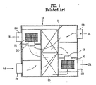
- A related art ventilating system will be described with reference to FIGS. 1 and 2.
- The related art ventilating system is provided with a
case 10 which is an exterior thereof, atotal heat exchanger 30 for making heat exchange between air being supplied/discharged to/from thecase 10, anair supply fan 41 and anair supply motor 42 for supplying air, and anair discharge fan 51 and anair discharge motor 52 for discharging air. - In one side of the
case 10, there is anoutdoor air inlet 21 for drawing outdoor air (OA), and aroom air outlet 24 for discharging exhaust air (EA). - In the meantime, in the other side of the
case 10, there is aroom air inlet 23 for drawing room air (RA), and anoutdoor air outlet 22 for supplying supply air (SA) to the room. - In the
case 10, there are a passage for guiding the outdoor air drawn through theoutdoor air inlet 21 to theoutdoor air outlet 22 through thetotal heat exchanger 30, and a passage for guiding the room air drawn through theroom air inlet 23 to theroom air outlet 24 through thetotal heat exchanger 30. - Behind the
room air outlet 24, there are theair discharge fan 51 and theair discharge motor 52 for forced discharge of the room air, and behind theoutdoor air outlet 22, there are theair supply fan 41 and theair supply motor 42 for forced supply of the outdoor air. - The operation of the heat exchange type ventilating system will be described.
- As the
air discharge fan 51 and theair discharge motor 52 come into operation, the polluted room air is introduced to thecase 10 through theroom air inlet 23, passes through thetotal heat exchanger 30, and is discharged to an outside of room through theroom air outlet 24. - At the same time with this, as the
air supply fan 41 and theair supply motor 42 come into operation, fresh outdoor air is introduced to thecase 10 through theoutdoor air inlet 21, passes through thetotal heat exchanger 30, and is supplied to the room through theoutdoor air inlet 22. - In the meantime, referring to FIG. 2, in spring/autumn when a temperature difference between the room and outdoor is not great, a
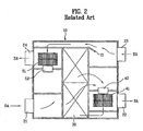
damper 11 is opened to make the room air discharged to an outside of the room directly through a bypass without passing through thetotal heat exchanger 30. - However, the related art ventilating system has the following problems.
- The
total heat exchanger 30 is operated in a principle in which air [in general, supply air (SA) and exhaust air (EA)] having a temperature difference is made to pass through passages separated by a high efficiency heat exchange membrane in theheat exchanger 30, to cause total heat exchange in the course of passing through the passages. - In the meantime, since there is the
air supply motor 42 in the air supply flow passage through which the outdoor air is drawn and supplied to the room, there is a problem of reduction of total heat exchange efficiency caused by rise of a temperature of the supply air coming from heat generated at theair supply motor 42. - In detail, the total heat exchange efficiency η is,
-

- Therefore, if the temperature of the supply air rises due to heat from the
air supply motor 42, the total heat exchange efficiency η is reduced. - Along with this, there has been a problem of difficulty of cutting off noise from the
air supply motor 42 and theair discharge motor 52. - Accordingly, the present invention is directed to a ventilating system that substantially obviates one or more problems due to limitations and disadvantages of the
- An object of the present invention is to provide a high efficiency total heat exchange ventilating system having high temperature efficiency and total heat exchange efficiency, by preventing a temperature of the supply air from rising by heat from the air supply motor.
- Additional advantages, objects, and features of the invention will be set forth in part in the description which follows and in part will become apparent to those having ordinary skill in the art upon examination of the following or may be learned from practice of the invention. The objectives and other advantages of the invention may be realized and attained by the structure particularly pointed out in the written description and claims hereof as well as the appended drawings.
- To achieve these objects and other advantages and in accordance with the purpose of the invention, as embodied and broadly described herein, a ventilating system includes a case which is an exterior of the ventilating system, a total heat exchanger in the case for making heat exchange between air discharged to an outside of room and air supplied to the room, an air supply fan and an air discharge fan mounted in the same direction with reference to the total heat exchanger, and an air supply motor and an air discharge motor for supplying power to the air supply fan and the air discharge fan, respectively, wherein the air supply fan is mounted in an air flow line of the air being supplied, and the air supply motor is isolated from the air supply fan and exposed to an air flow line of the air being discharged.
- The air discharge motor is also mounted in an air flow line of the air being discharged.
- On one side, the case includes an outdoor air inlet in communication with an outside of room, and a room air inlet in communication with the room, and on the other side, a room air outlet in communication with the outside of the room for discharging the room air to an outside of the room and an outdoor air outlet for supplying the outdoor air to the room.
- The case includes a passage connected between the outdoor air inlet and the outdoor air outlet through the total heat exchanger, and a passage connected between the room air inlet and the room air outlet through the total heat exchanger, wherein it is preferable that the outdoor air inlet and the outdoor air outlet, and the room air inlet and the room air outlet are arranged diagonally, respectively.
- The ventilating system further includes a bypass flow line in the case so that the air flows without passing through the total heat exchanger. The bypass flow line includes a damper for opening/closing the bypass flow line.
- The case includes spaces partitioned therein for housing the air supply fan and the air discharge fan respectively, and the air discharge motor and the air supply motor are housed in the air discharge fan housing having the air discharge fan housed therein, and the air supply motor and the air discharge motor are arranged in a line along a discharge air flow direction.
- The air discharge fan housing further includes a motor housing for accommodating the air discharge motor and the air supply motor, and the motor housing includes an opening on a side of the air discharge fan for passing of the air being discharged.
- In the meantime, the air supply fan and the air discharge fan may be centrifugal fans, and preferably sirocco fans.
- Thus, the ventilation system of the present invention has the following advantages.
- First, the exposure of the air discharge motor and the air supply motor not to an air supply flow line, but to an air discharge flow line permits to prevent reduction of total heat exchange efficiency caused by heat generated at the air supply motor.
- Second, the air supply motor and the air discharge motor can be cooled down adequately by the air being discharged.
- Third, the cutting off of noise from the air supply motor and the air discharge motor in one direction at the same time permits to enhance a noise cut-off effect.
- It is to be understood that both the foregoing general description and the following detailed description of the present invention are exemplary and explanatory and are intended to provide further explanation of the invention as claimed.
- The accompanying drawings, which are included to provide a further understanding of the invention and are incorporated in and constitute a part of this application, illustrate embodiment(s) of the invention and together with the description serve to explain the principle of the invention. In the drawings;
- FIG. 1 illustrates a diagram showing a total heat exchange state of a related art ventilating system;
- FIG. 2 illustrates a diagram showing a general ventilation state of the ventilating system in FIG. 1;
- FIG. 3 illustrates a diagram of a ventilating system in accordance with a preferred embodiment of the present invention; and
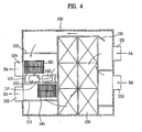
- FIG. 4 illustrates a diagram showing a general ventilation state of the ventilating system in FIG. 3.
- Reference will now be made in detail to the preferred embodiments of the present invention, examples of which are illustrated in the accompanying drawings. Wherever possible, the same reference numbers will be used throughout the drawings to refer to the same or like parts.
- Referring to FIGS. 3 and 4, a ventilating system in accordance with a preferred embodiment of the present invention will be described.
- The ventilating system is includes a
case 100 which is an exterior thereof, atotal heat exchanger 130 for making heat exchange between air being supplied/discharged, anair supply fan 141 and anair discharge fan 151 on one side of thetotal heat exchanger 130, and anair supply motor 142 and anair discharge motor 152 for supplying power to theair supply fan 141 and theair discharge fan 151, respectively. - In one side of the
case 100, there is anoutdoor air inlet 121 in communication with an outside of the room for drawing outdoor air (OA), and aroom air inlet 123 in communication with the room for drawing room air (RA). - In the other side of the
case 100, there is aroom air outlet 124 in communication with an outside of the room for discharging exhaust air (EA) to the outside of room, and anoutdoor air outlet 122 in communication with the room for supplying supply air (SA) to the room. - In the meantime, there are ducts (not shown) connected to the
outdoor air inlet 121, theroom air inlet 123, theoutdoor air outlet 122, and theroom air outlet 124, respectively. - In the
case 100, there are a passage for guiding the outdoor air (OA) drawn through theoutdoor air inlet 121 to theoutdoor air outlet 122 through thetotal heat exchanger 130, and a passage for guiding the room air (RA) drawn through theroom air inlet 123 to theroom air outlet 124 through thetotal heat exchanger 30. - In the
case 100, there is adamper 115 for opening/closing a bypass flow passage formed for air to flow without passing through thetotal heat exchanger 130. - In the
case 100, there are an airsupply fan housing 111 for housing theair supply fan 141 therein, and an airdischarge fan housing 112 for housing theair discharge fan 151 therein. - The air
supply fan housing 111 guides the outdoor air passed through thetotal heat exchanger 130 to theoutdoor air outlet 122, and the airdischarge fan housing 112 guides the room air passed through thetotal heat exchanger 130 to theroom air outlet 124. The airsupply fan housing 111 and the airdischarge fan housing 112 also serve to isolate the room air from the outdoor air. - In this instance, for cross flow of the outdoor air and the room air to make smooth heat exchange, it is preferable that the
outdoor air inlet 121 and theoutdoor air outlet 122, and theroom air inlet 123 and theroom air outlet 124 are arranged at positions diagonal to each other. - With reference to an air flow, the
air discharge fan 151 and theair discharge motor 152 are arranged in front of the room air outlet for forced discharge of the room air. On the other hand, with reference to an air flow, theair supply fan 141 and theair supply motor 142 are arranged in front of theoutdoor air outlet 122 for forced supply of the outdoor air. - The
air supply fan 141 and theair discharge fan 151 are arranged in parallel on one side of thetotal heat exchanger 130 such that theair supply motor 142 and theair discharge motor 152 are arranged on one line. - It is preferable that the
air supply fan 141 and theair discharge fan 151 are radial flow fans each of which receives air in an axial direction and discharged in a radial direction, particularly, sirocco fans. - The
air supply motor 142 and theair discharge motor 152 are arranged in the airdischarge fan housing 112. In detail, theair supply fan 141 and theair supply motor 142 are positioned separated by thepartition 114 which separates the airsupply fan housing 111 and the airdischarge fan housing 112, and theair supply motor 142 and theair discharge motor 152 are arranged in one line along a direction of discharge air flow. - Of course, positions of the
air supply motor 142 and theair discharge motor 152 may be interchanged. - This is for preventing the supply air (SA) from being involved in reduction of temperature efficiency, humidity efficiency, and total heat exchange efficiency caused by the heat generated at the
air supply motor 142 during the outdoor air passes through theair supply fan 141. - In detail, by isolating the
air supply motor 142 from theair supply fan 141, an influence of heat generated at theair supply motor 142 to the supply air is cut off, and along with this, theair supply motor 142 is cooled by the exhaust air passing through theair discharge fan 151. - In this instance, since the total heat exchange efficiency η is fixed by the outdoor air (OA), the room air (RA), and the supply air (SA), but not influenced from the exhaust air (EA), even if a temperature of the exhaust air (EA) rises by the heat generated at the
air supply motor 142 and theair discharge motor 152, the total heat exchange efficiency is not influenced by the heat. - In the air
discharge fan housing 112, there is amotor housing 113 for housing theair supply motor 142, and theair discharge motor 152. - It is preferable that, though the
motor housing 113 surrounds theair supply motor 142 and theair discharge motor 152, themotor housing 113 has an opening on a side of theair discharge fan 151 for introduction of the exhaust air thereto to cool down theair supply motor 142 and theair discharge motor 152. - In addition to this, the surrounding of the
air supply motor 142 and theair discharge motor 152 by themotor housing 113 cuts off noise from theair supply motor 142 and theair discharge motor 152. - The total heat exchange ventilation operation of the ventilation system of the present invention will be described.
- As power is applied to the
air discharge fan 151 at the time the room air is polluted, the room air (RA) is introduced to thecase 100 through theroom air inlet 123, and forcibly discharged to the outside of the room through theroom air outlet 124 by theair discharge fan 151 via thetotal heat exchanger 130. - At the same time with this, as power is applied to the
air supply fan 141, fresh outdoor air (OA) is introduced to thecase 100 through theoutdoor air inlet 121, and supplied to the room through theoutdoor air outlet 122 via thetotal heat exchanger 130. - In this instance, the room air (RA) passing through the
total heat exchanger 130 exchanges heat with the exhaust air (EA), to come to a state similar to a temperature and humidity with the room before being supplied to the room. - The exhaust air is introduced to the
air discharge fan 151, and cools theair supply motor 142 and theair discharge motor 152 as the exhaust air passes through themotor housing 113. - In the meantime, referring to FIG. 4, in spring/autumn when there is no great temperature difference between indoor/outdoor, a general ventilation is performed in which no total heat exchange is made between the exhaust (EA) and the outdoor air(OA).
- At first, the
damper 115 in thecase 100 is opened, to form a bypass flow line for the exhaust air (room air). Then, the room air (RA) drawn through theroom air inlet 123 is discharged to an outside of the room directly through theair discharge fan 151 via the bypass flow line without passing through thetotal heat exchanger 130. - The fresh outdoor air (OA) being supplied to the room is introduced to the base 100 through the
outdoor air inlet 121, passes through thetotal heat exchanger 130, and supplied to the room through theoutdoor air outlet 122. - In this instance, the exhaust air cools down the
air discharge motor 142 and theair supply motor 152 as the exhaust air passes through themotor housing 113. It will be apparent to those skilled in the art that various modifications and variations can be made in the present invention without departing from the spirit or scope of the inventions. Thus, it is intended that the present invention covers the modifications and variations of this invention provided they come within the scope of the appended claims and their equivalents.
Claims (14)
- A ventilating system comprising:a case which is an exterior of the ventilating system;a total heat exchanger in the case for making heat exchange between air discharged to an outside of room and air supplied to the room;an air supply fan and an air discharge fan mounted in the same direction with reference to the total heat exchanger; andan air supply motor and an air discharge motor for supplying power to the air supply fan and the air discharge fan, respectively, wherein the air supply fan is mounted in an air flow line of the air being supplied, and the air supply motor is isolated from the air supply fan and exposed to an air flow line of the air being discharged.
- The ventilating system as claimed in claim 1, wherein the air discharge motor is mounted in an air flow line of the air being discharged.
- The ventilating system as claimed in claim 1 or 2, wherein on one side, the case includes an outdoor air inlet in communication with an outside of room, and a room air inlet in communication with the room, and on the other side, a room air outlet in communication with the outside of the room for discharging the room air to an outside of the room and an outdoor air outlet for supplying the outdoor air to the room.
- The ventilating system as claimed in claim 3, wherein the case includes;
a passage connected between the outdoor air inlet and the outdoor air outlet through the total heat exchanger, and
a passage connected between the room air inlet and the room air outlet through the total heat exchanger. - The ventilating system as claimed in claim 3 or 4, wherein the outdoor air inlet and the outdoor air outlet, and the room air inlet and the room air outlet are arranged diagonally, respectively.
- The ventilating system as claimed in any of claims 1 to 5, further comprising a bypass flow line in the case so that the air flows without passing through the total heat exchanger.
- The ventilating system as claimed in claim 6, further comprising a damper for opening/closing the bypass flow line.
- The ventilating system as claimed in any of claims 1 to 7, wherein the air supply motor and the air discharge motor are arranged in a line along a discharge air flow direction.
- The ventilating system as claimed in any of claims 1 to 8, wherein the case includes spaces partitioned therein for housing the air supply fan and the air discharge fan respectively, and the air discharge motor and the air supply motor are housed in an air discharge fan housing having the air discharge fan housed therein.
- The ventilating system as claimed in claim 9, wherein the air discharge fan housing further includes a motor housing for accommodating the air discharge motor and the air supply motor.
- The ventilating system as claimed in claim 10, wherein the motor housing includes an opening on a side of the air discharge fan for passing of the air being discharged.
- The ventilating system as claimed in any of claims 1 to 11, wherein the air supply fan and the air discharge fan are centrifugal fans.
- The ventilating system as claimed in any of claims 1 to 11, wherein the air supply fan and the air discharge fan are sirocco fans.
- A method of operating a ventilating system according to any of claims 1 to 13.
Applications Claiming Priority (1)
| Application Number | Priority Date | Filing Date | Title |
|---|---|---|---|
| KR1020050039373A KR100628090B1 (en) | 2005-05-11 | 2005-05-11 | Ventilation system |
Publications (1)
| Publication Number | Publication Date |
|---|---|
| EP1722170A1 true EP1722170A1 (en) | 2006-11-15 |
Family
ID=36791618
Family Applications (1)
| Application Number | Title | Priority Date | Filing Date |
|---|---|---|---|
| EP06009785A Withdrawn EP1722170A1 (en) | 2005-05-11 | 2006-05-11 | Ventilating system |
Country Status (5)
| Country | Link |
|---|---|
| US (1) | US20060254749A1 (en) |
| EP (1) | EP1722170A1 (en) |
| JP (1) | JP5005952B2 (en) |
| KR (1) | KR100628090B1 (en) |
| CN (1) | CN1862124A (en) |
Cited By (3)
| Publication number | Priority date | Publication date | Assignee | Title |
|---|---|---|---|---|
| EP2357365A3 (en) * | 2010-02-01 | 2012-04-25 | Brink Climate Systems B.V. | Air movement system |
| FR2995387A1 (en) * | 2012-09-12 | 2014-03-14 | Aldes Aeraulique | HOUSING FOR CONTROLLED MECHANICAL VENTILATION GROUP WITH DOUBLE FLOW OF A LOCAL |
| EP3153807A1 (en) * | 2015-08-14 | 2017-04-12 | Trane International Inc. | Heat exchange assembly in an air to air heat exchanger |
Families Citing this family (12)
| Publication number | Priority date | Publication date | Assignee | Title |
|---|---|---|---|---|
| KR100838870B1 (en) | 2005-11-14 | 2008-06-16 | 엘지전자 주식회사 | Ventilation |
| KR100747802B1 (en) * | 2005-11-14 | 2007-08-08 | 엘지전자 주식회사 | Ventilation and control method |
| JP5003650B2 (en) * | 2008-10-21 | 2012-08-15 | パナソニック株式会社 | Heat exchange equipment |
| JP4697341B2 (en) * | 2009-07-08 | 2011-06-08 | ダイキン工業株式会社 | Ventilation system |
| KR101083598B1 (en) | 2009-10-23 | 2011-11-16 | (주)센도리 | Inlet and outlet expansion type heat exchange ventilation |
| CN102305448A (en) * | 2011-09-23 | 2012-01-04 | 广东朗能电器有限公司 | Total heat exchanger |
| KR101149815B1 (en) | 2012-01-19 | 2012-05-24 | 은성화학(주) | Ventilating unit having total heat exchanger |
| CN105091267A (en) * | 2015-09-08 | 2015-11-25 | 中国建筑科学研究院 | Fresh air ventilator with energy recovery function |
| KR101921206B1 (en) | 2018-06-18 | 2019-02-13 | 최성철 | A Air purifier combined with ventilation |
| JP7507340B2 (en) * | 2020-07-22 | 2024-06-28 | パナソニックIpマネジメント株式会社 | Heat exchange ventilation system |
| JP2024049430A (en) * | 2022-09-29 | 2024-04-10 | パナソニックIpマネジメント株式会社 | Heat exchange ventilation system |
| WO2024261983A1 (en) * | 2023-06-22 | 2024-12-26 | 三菱電機株式会社 | Heat exchange-type ventilation device |
Citations (4)
| Publication number | Priority date | Publication date | Assignee | Title |
|---|---|---|---|---|
| US5070934A (en) * | 1988-05-30 | 1991-12-10 | Siegenia-Frank Kg | Ventilation device with heat recovery |
| US5119987A (en) * | 1990-03-31 | 1992-06-09 | Kabushiki Kaisha Toshiba | Ventilating apparatus |
| WO1999043992A1 (en) * | 1998-02-27 | 1999-09-02 | Georges Spoehrle | Modular, prefabricated and integrated device for heating and ventilating the premises of a building |
| DE19903280A1 (en) * | 1999-01-28 | 2000-08-10 | Theodor Blum | Ventilation device has Peltier element(s) for cooling or heating fresh air flow between fresh air chamber and outgoing air chamber or between incoming air chamber and used air chamber |
Family Cites Families (8)
| Publication number | Priority date | Publication date | Assignee | Title |
|---|---|---|---|---|
| GB2179437B (en) * | 1985-08-19 | 1989-09-13 | Toshiba Kk | Ventilator |
| CA2134168C (en) * | 1994-10-24 | 2002-06-11 | Frederic Lagace | Ventilation system |
| JP3660955B2 (en) * | 1996-01-23 | 2005-06-15 | ダイキン工業株式会社 | Heat exchange ventilator |
| JPH1047724A (en) * | 1996-07-31 | 1998-02-20 | Mitsubishi Electric Corp | Heat exchange ventilator |
| JP2001263754A (en) * | 2000-03-15 | 2001-09-26 | Sanyo Electric Co Ltd | Ventilation fan |
| JP3506251B2 (en) * | 2003-09-18 | 2004-03-15 | 三菱電機株式会社 | Ventilation air conditioning system and ventilation air conditioning unit |
| CA2447351C (en) * | 2003-10-30 | 2007-09-04 | Trent Metals Limited | Heat recovery ventilator |
| KR100590329B1 (en) * | 2004-05-14 | 2006-06-19 | 엘지전자 주식회사 | Ventilation |
-
2005
- 2005-05-11 KR KR1020050039373A patent/KR100628090B1/en not_active Expired - Fee Related
-
2006
- 2006-05-10 US US11/382,569 patent/US20060254749A1/en not_active Abandoned
- 2006-05-11 JP JP2006132789A patent/JP5005952B2/en not_active Expired - Fee Related
- 2006-05-11 EP EP06009785A patent/EP1722170A1/en not_active Withdrawn
- 2006-05-11 CN CNA2006100817893A patent/CN1862124A/en active Pending
Patent Citations (4)
| Publication number | Priority date | Publication date | Assignee | Title |
|---|---|---|---|---|
| US5070934A (en) * | 1988-05-30 | 1991-12-10 | Siegenia-Frank Kg | Ventilation device with heat recovery |
| US5119987A (en) * | 1990-03-31 | 1992-06-09 | Kabushiki Kaisha Toshiba | Ventilating apparatus |
| WO1999043992A1 (en) * | 1998-02-27 | 1999-09-02 | Georges Spoehrle | Modular, prefabricated and integrated device for heating and ventilating the premises of a building |
| DE19903280A1 (en) * | 1999-01-28 | 2000-08-10 | Theodor Blum | Ventilation device has Peltier element(s) for cooling or heating fresh air flow between fresh air chamber and outgoing air chamber or between incoming air chamber and used air chamber |
Cited By (5)
| Publication number | Priority date | Publication date | Assignee | Title |
|---|---|---|---|---|
| EP2357365A3 (en) * | 2010-02-01 | 2012-04-25 | Brink Climate Systems B.V. | Air movement system |
| FR2995387A1 (en) * | 2012-09-12 | 2014-03-14 | Aldes Aeraulique | HOUSING FOR CONTROLLED MECHANICAL VENTILATION GROUP WITH DOUBLE FLOW OF A LOCAL |
| WO2014041309A1 (en) * | 2012-09-12 | 2014-03-20 | Aldes Aeraulique | Casing for a dual flow controlled mechanical ventilation unit of a room |
| EP3153807A1 (en) * | 2015-08-14 | 2017-04-12 | Trane International Inc. | Heat exchange assembly in an air to air heat exchanger |
| US10527367B2 (en) | 2015-08-14 | 2020-01-07 | Trane International Inc. | Heat exchange assembly in an air to air heat exchanger |
Also Published As
| Publication number | Publication date |
|---|---|
| US20060254749A1 (en) | 2006-11-16 |
| JP5005952B2 (en) | 2012-08-22 |
| JP2006317143A (en) | 2006-11-24 |
| CN1862124A (en) | 2006-11-15 |
| KR100628090B1 (en) | 2006-09-26 |
Similar Documents
| Publication | Publication Date | Title |
|---|---|---|
| EP1722170A1 (en) | Ventilating system | |
| US6705833B2 (en) | Airflow flapper valve | |
| KR20190003541A (en) | Compact heat recovery ventilation system | |
| US20050287945A1 (en) | Ventilating system | |
| US20120131944A1 (en) | Air moving unit and a hvac system employing the same | |
| US7558063B2 (en) | Server with a flexible cooling scheme | |
| WO1999024762A1 (en) | Air circulation system and method with return duct ventilation | |
| EP3604944B1 (en) | Ventilation device | |
| CN116538585B (en) | Energy-saving vertical air circulator suitable for dual-shaft motors and dual fans | |
| KR101843856B1 (en) | By-pass apparatus for a ventilation system | |
| KR20170121111A (en) | By-pass apparatus for a ventilation system | |
| KR20160087407A (en) | By-pass apparatus for ventilation system | |
| CN111503764A (en) | Fan equipment for fresh air system and method for carrying out air exchange by using fan equipment | |
| KR100352443B1 (en) | structure of air discharger in air conditioner | |
| KR20170010304A (en) | By-pass apparatus for a ventilation system | |
| KR100698910B1 (en) | Duct type air conditioner | |
| KR102714030B1 (en) | Emergency Power Generation System Equipped with Load Bank | |
| JP2002162082A (en) | Heat exchange cooling device | |
| KR100628091B1 (en) | Ventilation system | |
| JP3276941B2 (en) | Air conditioner | |
| CN112665074B (en) | Single-pipeline fan equipment and method for exchanging air by using same | |
| KR20170113721A (en) | By-pass apparatus for a ventilation system | |
| KR20160041176A (en) | Damper and by-pass apparatus for ventilation system having the same | |
| JPH10300123A (en) | Ventilation air conditioner for control room of nuclear power plant | |
| CN117704488A (en) | Fresh air device and fresh air conditioner with same |
Legal Events
| Date | Code | Title | Description |
|---|---|---|---|
| PUAI | Public reference made under article 153(3) epc to a published international application that has entered the european phase |
Free format text: ORIGINAL CODE: 0009012 |
|
| 17P | Request for examination filed |
Effective date: 20060608 |
|
| AK | Designated contracting states |
Kind code of ref document: A1 Designated state(s): AT BE BG CH CY CZ DE DK EE ES FI FR GB GR HU IE IS IT LI LT LU LV MC NL PL PT RO SE SI SK TR |
|
| AX | Request for extension of the european patent |
Extension state: AL BA HR MK YU |
|
| 17Q | First examination report despatched |
Effective date: 20070618 |
|
| AKX | Designation fees paid |
Designated state(s): DE FR GB IT |
|
| STAA | Information on the status of an ep patent application or granted ep patent |
Free format text: STATUS: THE APPLICATION IS DEEMED TO BE WITHDRAWN |
|
| 18D | Application deemed to be withdrawn |
Effective date: 20071030 |