EP1722111A1 - Befestigungselement zur Befestigung eines Metallprofils auf einem Träger - Google Patents
Befestigungselement zur Befestigung eines Metallprofils auf einem Träger Download PDFInfo
- Publication number
- EP1722111A1 EP1722111A1 EP06290772A EP06290772A EP1722111A1 EP 1722111 A1 EP1722111 A1 EP 1722111A1 EP 06290772 A EP06290772 A EP 06290772A EP 06290772 A EP06290772 A EP 06290772A EP 1722111 A1 EP1722111 A1 EP 1722111A1
- Authority
- EP
- European Patent Office
- Prior art keywords
- base
- support
- fastening device
- plane
- wing
- Prior art date
- Legal status (The legal status is an assumption and is not a legal conclusion. Google has not performed a legal analysis and makes no representation as to the accuracy of the status listed.)
- Granted
Links
- 239000002184 metal Substances 0.000 title claims abstract description 8
- 230000000712 assembly Effects 0.000 claims 1
- 238000000429 assembly Methods 0.000 claims 1
- 229910000831 Steel Inorganic materials 0.000 abstract description 4
- 239000010959 steel Substances 0.000 abstract description 4
- 238000009434 installation Methods 0.000 description 5
- 238000004519 manufacturing process Methods 0.000 description 3
- 239000000463 material Substances 0.000 description 3
- 241000446313 Lamella Species 0.000 description 2
- 238000005520 cutting process Methods 0.000 description 2
- 238000004026 adhesive bonding Methods 0.000 description 1
- 238000000576 coating method Methods 0.000 description 1
- 230000000295 complement effect Effects 0.000 description 1
- 239000000470 constituent Substances 0.000 description 1
- 238000010276 construction Methods 0.000 description 1
- 230000000694 effects Effects 0.000 description 1
- 229910052602 gypsum Inorganic materials 0.000 description 1
- 239000010440 gypsum Substances 0.000 description 1
- 230000003014 reinforcing effect Effects 0.000 description 1
- 230000000717 retained effect Effects 0.000 description 1
- 238000003466 welding Methods 0.000 description 1
Images


Classifications
-
- E—FIXED CONSTRUCTIONS
- E04—BUILDING
- E04B—GENERAL BUILDING CONSTRUCTIONS; WALLS, e.g. PARTITIONS; ROOFS; FLOORS; CEILINGS; INSULATION OR OTHER PROTECTION OF BUILDINGS
- E04B9/00—Ceilings; Construction of ceilings, e.g. false ceilings; Ceiling construction with regard to insulation
- E04B9/18—Means for suspending the supporting construction
-
- E—FIXED CONSTRUCTIONS
- E04—BUILDING
- E04B—GENERAL BUILDING CONSTRUCTIONS; WALLS, e.g. PARTITIONS; ROOFS; FLOORS; CEILINGS; INSULATION OR OTHER PROTECTION OF BUILDINGS
- E04B9/00—Ceilings; Construction of ceilings, e.g. false ceilings; Ceiling construction with regard to insulation
- E04B9/06—Ceilings; Construction of ceilings, e.g. false ceilings; Ceiling construction with regard to insulation characterised by constructional features of the supporting construction, e.g. cross section or material of framework members
- E04B9/12—Connections between non-parallel members of the supporting construction
- E04B9/16—Connections between non-parallel members of the supporting construction the members lying in different planes
-
- F—MECHANICAL ENGINEERING; LIGHTING; HEATING; WEAPONS; BLASTING
- F16—ENGINEERING ELEMENTS AND UNITS; GENERAL MEASURES FOR PRODUCING AND MAINTAINING EFFECTIVE FUNCTIONING OF MACHINES OR INSTALLATIONS; THERMAL INSULATION IN GENERAL
- F16B—DEVICES FOR FASTENING OR SECURING CONSTRUCTIONAL ELEMENTS OR MACHINE PARTS TOGETHER, e.g. NAILS, BOLTS, CIRCLIPS, CLAMPS, CLIPS OR WEDGES; JOINTS OR JOINTING
- F16B2/00—Friction-grip releasable fastenings
- F16B2/20—Clips, i.e. with gripping action effected solely by the inherent resistance to deformation of the material of the fastening
- F16B2/22—Clips, i.e. with gripping action effected solely by the inherent resistance to deformation of the material of the fastening of resilient material, e.g. rubbery material
- F16B2/24—Clips, i.e. with gripping action effected solely by the inherent resistance to deformation of the material of the fastening of resilient material, e.g. rubbery material of metal
- F16B2/241—Clips, i.e. with gripping action effected solely by the inherent resistance to deformation of the material of the fastening of resilient material, e.g. rubbery material of metal of sheet metal
- F16B2/245—Clips, i.e. with gripping action effected solely by the inherent resistance to deformation of the material of the fastening of resilient material, e.g. rubbery material of metal of sheet metal external, i.e. with contracting action
-
- F—MECHANICAL ENGINEERING; LIGHTING; HEATING; WEAPONS; BLASTING
- F16—ENGINEERING ELEMENTS AND UNITS; GENERAL MEASURES FOR PRODUCING AND MAINTAINING EFFECTIVE FUNCTIONING OF MACHINES OR INSTALLATIONS; THERMAL INSULATION IN GENERAL
- F16B—DEVICES FOR FASTENING OR SECURING CONSTRUCTIONAL ELEMENTS OR MACHINE PARTS TOGETHER, e.g. NAILS, BOLTS, CIRCLIPS, CLAMPS, CLIPS OR WEDGES; JOINTS OR JOINTING
- F16B7/00—Connections of rods or tubes, e.g. of non-circular section, mutually, including resilient connections
- F16B7/04—Clamping or clipping connections
- F16B7/044—Clamping or clipping connections for rods or tubes being in angled relationship
- F16B7/048—Clamping or clipping connections for rods or tubes being in angled relationship for rods or for tubes without using the innerside thereof
- F16B7/0493—Clamping or clipping connections for rods or tubes being in angled relationship for rods or for tubes without using the innerside thereof forming a crossed-over connection
Definitions
- the present invention relates, in a general manner, the fixing on a support of a metal profile of the fur type or any other frame element capable of receiving a facing.
- the profiles to be used to support such plates extend transversely relative to the vertical uprights carrying the assembly and, for their attachment to each of these amounts, at their intersection with such an amount, it is implemented locally a fixing lug comprising generally, on the one hand, a base, by which the tab is adapted to be subject to the support that constitutes this amount and, secondly, a head to which can be secured, for example by snapping, the fur concerned.
- a fastening lug consisting of two separate fasteners, arranged on either side of a support and which, once fixed to one another by fastening means, jointly enclose the support.
- the fasteners each have two wings perpendicular to one another: a first lateral wing, forming half of the base, by which the fasteners bear on the support, each respectively on two opposite sides of the support, forming together the corresponding base, and a second central wing.
- the second central wing of a fastener comprises fastening means which, in cooperation with complementary fastening means provided on the central flange of the other fastener, ensure the fastening of the fasteners relative to one another.
- the present invention thus relates to a fixing device for a metal profile to be carried on a support, of the kind comprising a base intended to be secured to the support and a body provided with a head intended to be secured to the profile, characterized in that the fixing device is formed in one piece in which the base comprises two parts, at least one of which is resilient with respect to the other and which are provided with respective support means for jointly gripping the support on two sides opposite of the latter, the support means of one of the parts of the base, called the first part, comprising at least one detent member facing the support means of the other part of the base , called second part, the support means of the second part forming retaining means oriented towards said at least one latching member.
- the support means forming retaining means are intended to engage a first rim of the support to cooperate with this rim and prevent any withdrawal perpendicular to the direction of engagement.
- Said at least one locking member, for its part, is intended to be snapped onto a second opposite edge of the support under the action of a thrust exerted on the fixing device substantially perpendicular to the direction of engagement of the other means. of support, after engagement of the latter on the first edge of the support.
- the fixing device being in one piece, it does not require additional assembly operation of intermediate elements to form the device, in addition to the mounting operation of the device on the support.
- the latter can be easily clipped onto the support, which makes assembly easy.
- the mounting of the fixing device according to the invention requires no tools.
- said at least one latching member has a general shape of the type comprising a ramp oriented facing the bearing means of the second part of the base and ending with a return.
- the attachment piece comprises a wing which, on the one hand, comprises the head at one end and, on the other hand, separates towards the opposite end of the wing in three portions of wing extending substantially in the same plane, two of the three wing portions being extended to form one of the parts of the base while the third wing portion is extended to form the other part of the base .
- the two wing portions extended to form one of the parts of the base are arranged on either side of the third wing portion.
- the first part of the base extends substantially in the same plane, called the first plane P 1 , that in which the three wing portions extend, while the second part of the base extends successively in a second plane P 2 substantially perpendicular to the first plane and in a plane parallel to the first plane.
- the support means of the first part of the base comprise two detent members located substantially at the same distance from the head and spaced apart from each other in the first plane.
- the third wing portion is extended to form the first portion of the base.
- the second part of the base comprises a plate which extends in a plane substantially perpendicular to that in which extends the body of the part, the support means of the second part being secured to this plate, the flange of the assembly extending substantially perpendicularly to the plate and the return extending substantially parallel to the plate .
- the two wing portions are extended to the plate of the second part of the base by means of two straps spaced from one another and extending substantially in the second plane.
- a play catch-up system is provided on the base.
- cutouts are made in the plate so as to constitute a free elastic strip on three sides, said strip being provided with at least one boss on a face of the plate to be arranged against the support.
- the one or more detent members each have a form of retaining lug.
- the part in profile view has the general shape of a seat, a part of the base forming the seat of the seat, while the support means of the first and second parts of the seat form the feet, the body provided with the head forming the seat back.
- a fixing device according to the invention is shown in the figures and designated by the general reference denoted 10.
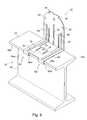
- Such a device is, for example, used for fixing metal profiles of the fur type on a metal frame, especially steel, a house.
- the frame is for example constituted by uprights or vertical supports 12, formed, for example, of I-section cross-section profiles.
- the support 12 comprises a core 14 and two wings 16 arranged parallel to each other.
- the profile 18 is, for example, a C-section cross section which has a flange 20 and two lateral flanges 22 provided, along their free edge, back returns 24.
- a facing for example vertical, formed of plates (not shown) arranged contiguously to each other is then fixed on the profiles 18 in place on the fastening devices 10.
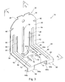
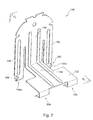
- the device 10 generally comprises a wing-shaped body 30 provided at one of its ends, said upper end, with a head 32 intended to at the fixing of the profile 18 ( Figures 2a to 2c) and connected at its opposite end, said lower, to a base 34 for mounting the device on the support 12.
- This device formed in one piece is obtained from a metal blank, especially steel, by simple cutting and folding operations, without the need to perform other operations such as, for example , assemble different elements together, particularly by welding, gluing, interlocking ...
- the device has a general shape of L, the aforementioned wing forming the vertical leg of L located in a first plane P 1 , while the horizontal leg of L, located in a second plane P 2 , forms part of the base (Figure 3).
- the fixing device is symmetrical with respect to a third plane P 3 , perpendicular to the planes P 1 and P 2 , and which is vertical in FIG.
- the head 32 of generally rounded shape comprises, arranged symmetrically with respect to this plane, two pairs of notches: a first pair of notches 36, 38, arranged near the free end of the head and intended to favor the mounting of the profile 18 ( Figures 2a to 2c), and a second pair of notches 40, 42, arranged at a distance from the free end of the head, in its widest part, and which are intended for hanging definitive profile (Figure 2c).
- Two portions, 48, 52, among the three wing portions are disposed on either side of the plane of symmetry P 3 so as to frame the third wing portion 50.
- the two wing portions 48, 52 are extended in the second plane P 2 , after folding at right angles, along the fold lines 54, 56, of the part of the device opposite to that carrying the head, in the form of two braces 58, 60 spaced from each other the same distance as the portions 48,52.
- the straps 58, 60 join a plate 62 arranged in the same plane P 2 .
- This plate is provided at its free end, that is to say the one opposite the end connected to the shoulder straps, bearing means 64, 66 symmetrical with respect to the plane of symmetry P 3 and arranged in the respective alignment two wing portions 48, 52 and shoulder straps 58, 60.
- These support means are each in the form of an assembly successively formed by a flange 64a, 66a extending substantially perpendicular to the plane P 2 of the plate, from the free end thereof, and a return 64b, 66b extending substantially parallel to the plane P 2 .
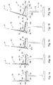
- Each return 64b, 66b has a free end which deviates obliquely with respect to the plate so as to facilitate the engagement of the device 10 on the support 12 ( Figure 1a).
- the support means may, alternatively, be formed of a single rim and a single return extending from the support means 64 to the support means 66 over the entire dimension of the plate.
- the fastening device according to the invention also comprises a backlash system 68 which serves to compensate for possible mechanical clearances between the fastening device 10 and its support 12 during assembly, and which result, for example, manufacturing tolerances of different manufacturers and / or possible coatings deposited on the support 12.
- This system ensures a permanent contact between the fixing device and the support, which avoids in case of play, under certain conditions of use such as those where the device is installed in the attic of a home in which wind can rushing, a sound of slamming the device on the support under the action of the wind.
- the system 68 is in the form of an elastic strip 70 made in the plate 62 by two parallel cuts 72, 74 which leave the strip free on three sides.
- the elastic strip 70 is oriented towards the flange 30, that is to say in the direction opposite to the free end of the plate and to the support means 64, 66.
- the resilient lamella 70 has a boss 76 (Figure 4) on the face of the plate which is intended to be arranged against the support 12 ( Figures 1a to 1e). Only the corresponding hollow on the opposite face of the plate is visible in FIG.
- the third wing portion 50 extends into the first plane P 1 , beyond the plane in which the plate 62 is arranged, to a free end 50a and thus forms a tab endowed with an elastic nature with respect to the remainder of the device and, in particular, the plate 62 equipped with its support means.
- This elasticity makes it possible, in particular at the free end 50a of the tab, to move perpendicular to the first plane P 1 (FIGS. 1a to 1e).
- the free end 50a is provided with support means 80, 82 oriented facing the support means 64, 66 and which are able, with the latter, to clamp together the support 12 ( Figures 1a to 1e).
- the support means 80, 82 are closer to one another than the means 64, 66 since they are in the extension of the elastic tab 50, whereas the means 64, 66 are in alignment with the two respective wing portions 48, 52.
- Each of the support means 80, 82 located equidistant from the head 32 constitutes a separate latching member which is adapted to be snapped onto a rim of the support 12, as shown in FIGS. 1a to 1e, under FIG. action of a thrust exerted on the device 10, without resorting to a tool.
- the latching member performs the function of a retaining lug to prevent withdrawal of the fastener after mounting on the support 12 ( Figure 1e).
- the play-catching system makes it possible to ensure that the bearing means 80, 82 are always in contact with the underside of the rim of the support.
- Disassembly of the fixing device is however possible by laterally separating the latching members of the support by the elasticity of the tab 50, for example, in case of repositioning of the device.
- the latching member 80 (82) has a general shape of the type comprising a ramp 80a (82a) directed towards the inside of the device, that is to say facing the bearing means of the plate 62, so as to cooperate with the support during the mounting operation ( Figures 1 to 1e), and ending with a return 80b (resp.82b) which provides a retaining function of the bracket.
- the ramp is arranged substantially in alignment with the folded free edge and inclined outwardly of the device so that the engagement of the elastic tab 50 is further facilitated ( Figures 1a, 1b).
- Each ratchet member, of triangular shape, is obtained by cutting and folding from one of the two corners of the free end 50a of the tab 50.
- the free end 50a may alternatively comprise only one detent member instead of the two which are shown in the figures.
- this single latching member may extend from the member 80 to the member 82 and thus bring together the latter two.
- the concave portions of the ribs 90, 94 are arranged on the inner side of the fixing lug visible in FIGS. 3 and 6, whereas the concave portion of the rib 92 is arranged on the outer side of the wing 30 visible in FIG. .
- stiffening means are useful for compensating for a small thickness of the fixing device 10.
- the thickness of the device depends on the volume of material that it is desired to use.
- the thickness of the steel device is 0.8 mm.
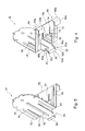
- the configuration of the fastening device 10 between the three wing portions 48, 50, 52 is reversed, which leads to the attachment device 100.
- two wing portions 148, 152 flanking a third wing portion 150 are extended in the plane P 1 beyond the plane P 2 , so as to form two elastic tabs with free ends 148a, 152a each provided with at least one latching member 180, 182 identical respectively to the latching members 80,82.
- the third wing portion 150 is extended in the plane P 2 , after folding, in the form of a ramp 158 which widens to form a plate 162 of dimensions corresponding to those of the plate 62.
- the plate 162 is provided at its free end with bearing means 164, 166 of the type successively comprising a flange and a return, such as the means 64 and 66 of FIG.
- the configuration of the fastening device 10 between the three wing portions 48, 50, 52 is retained, but in the device 200, the third portion 250 is folded to right angle in the plane P 2 , in the opposite direction of the two wing portions 248, 252 which extend in the same plane in the form of respective straps 258, 260, joined at their free ends by a strip 262.
- a flange 264 and a return 266 are successively formed from the strip 262 to form support means 268 over the entire dimension (width) of the device.
- the third portion 250 is then again bent at right angles downwards, in the plane P 1 , so as to form a free end 250a similar to the free end 50a of FIGS. 3 to 6. For this purpose, it is necessary to have a leg of greater length than the tab 50.
- the free end 50a (respectively 250a or 148a and 152a) of the tab 50 (or 250 or tabs 148, 150) provided with its means support is a first part of the base 34 of the fastening device 10 (respectively 200 or 100), while the assembly formed of the plate 62 provided with its support means and straps 58, 60 (resp. 258, 260 and support means 268 or plate 162 and support means 164, 166) constitutes a second part of the base.
- the first part of the base formed from the wing 30 and equipped with at least one detent member is resilient with respect to the second part of the base, also formed to from the wing 30 and equipped with support means.
- This elasticity makes it possible, as represented in FIGS. 1 a to 1 e and 6, to very easily mount the fastening device 10 (respectively 200 or 100) on the support 12 and, in particular, on one of its wings 16.
- the bearing means 364, 366 of the second part of the base of the fixing device 300 can also be made in the form of a or several detent members 368, 370 similar to the members 80, 82 to increase the ease of mounting of the device.
- each locking member 368, 370 can be bent outwards from the device in an inclined manner such as the free edge 84 of the tab 50.
- the constituent part of the fastening device according to the invention has, in a profile view such as one of those shown in Figures 1a to 1e, the general shape of a seat.
- Part of the base of the part namely the horizontal part, forms the seat of the seat, while the support means of the first and second parts of the base form the feet of the seat, the body of the part the head is the back of the seat.
- the installation of the fixing device 10 begins with the positioning of the support means 64, 66 of the second part of the base 34 against one 16a of the sides 16a, 16b of a wing 16 of the support 12.
- the device is tilted so as to bring the first part of the base into contact with the support. More particularly, under the action of a thrust exerted on the head of the device in the direction indicated by the arrow referenced F (for example on the head 32), the flared free edge 84 of the first part of the base comes into support on the upper edge 16c of the side 16b of the support 12 ( Figure 1a) and slides on the latter, which has the effect of elastically deforming the tab 50, then it is the turn of the ramps 80a, 82a of the tab 50 ( Figure 1b) to slide on the upper edge 16c.
- a thrust exerted on the head of the device in the direction indicated by the arrow referenced F for example on the head 32
- the elastic strip 70 has deformed away from the plane P 2 of the plate by a distance which is sufficient to make up any mechanical play between the device 10 and the support and thus obtain a calibration in position of the device on the support.
- FIG. 6 illustrates the position of the slat 70 slightly raised when the fixing device 10 is subjected to the support 12.
- the fastening device 10 is then firmly anchored to the support 12 and the profile 18 can be installed as shown in Figures 2a to 2c.
- One of the returns 24, the right return, of the profile is first introduced into the upper right notch 38 of the head 32 of the device, while the other return 24, the left return, is engaged in the opening the lower left notch 40, the profile being then arranged crooked ( Figure 2a).
- the right return 24 of the profile 18 Continuing to move down the right return 24 of the profile 18 on the rounded contour of the head, in the enlarged area of the latter, thanks to a certain elasticity of the profile, the right return 24 eventually meet the bottom right notch 42 and lodge there. The profile 18 is then firmly anchored to the fastening device 10.
Landscapes
- Engineering & Computer Science (AREA)
- Architecture (AREA)
- General Engineering & Computer Science (AREA)
- Civil Engineering (AREA)
- Physics & Mathematics (AREA)
- Electromagnetism (AREA)
- Mechanical Engineering (AREA)
- Structural Engineering (AREA)
- Connection Of Plates (AREA)
- Clamps And Clips (AREA)
- Coating With Molten Metal (AREA)
- Gripping Jigs, Holding Jigs, And Positioning Jigs (AREA)
- Flanged Joints, Insulating Joints, And Other Joints (AREA)
- Insertion Pins And Rivets (AREA)
Applications Claiming Priority (1)
| Application Number | Priority Date | Filing Date | Title |
|---|---|---|---|
| FR0504771A FR2885652B1 (fr) | 2005-05-12 | 2005-05-12 | Dispositif de fixation destine a la fixation d'un profile metallique sur un support |
Publications (2)
| Publication Number | Publication Date |
|---|---|
| EP1722111A1 true EP1722111A1 (de) | 2006-11-15 |
| EP1722111B1 EP1722111B1 (de) | 2009-04-08 |
Family
ID=35149578
Family Applications (1)
| Application Number | Title | Priority Date | Filing Date |
|---|---|---|---|
| EP06290772A Active EP1722111B1 (de) | 2005-05-12 | 2006-05-12 | Befestigungselement zur Befestigung eines Metallprofils auf einem Träger |
Country Status (4)
| Country | Link |
|---|---|
| EP (1) | EP1722111B1 (de) |
| AT (1) | ATE428058T1 (de) |
| DE (1) | DE602006006110D1 (de) |
| FR (1) | FR2885652B1 (de) |
Cited By (4)
| Publication number | Priority date | Publication date | Assignee | Title |
|---|---|---|---|---|
| EP1930668A2 (de) * | 2006-12-04 | 2008-06-11 | IDEEMATEC Deutschland GmbH | Montageschienensystem |
| FR2917106A1 (fr) * | 2007-06-11 | 2008-12-12 | Brigitte Helene Marguerite Cauvin | "dispositif d'accrochage de corniere" |
| EP2425169A1 (de) * | 2009-04-27 | 2012-03-07 | Unirac, Inc. | Schnappvebinder für bauelemente |
| US20230011291A1 (en) * | 2021-07-12 | 2023-01-12 | Chiao-Yin CHANG | Corner bracket with reinforcing ribs |
Citations (3)
| Publication number | Priority date | Publication date | Assignee | Title |
|---|---|---|---|---|
| US3608857A (en) * | 1969-12-11 | 1971-09-28 | Richard H Hibbeler | Channel clip for t-bars |
| FR2622259A1 (fr) * | 1987-10-21 | 1989-04-28 | Placoplatre Sa | Patte de fixation pour fourrure a rapporter sur un support, et attache propre a la constitution d'une telle patte de fixation |
| US6327758B1 (en) * | 1999-11-01 | 2001-12-11 | Juno Manufacturing, Inc. | Resilient unitary lighting clip |
-
2005
- 2005-05-12 FR FR0504771A patent/FR2885652B1/fr not_active Expired - Fee Related
-
2006
- 2006-05-12 AT AT06290772T patent/ATE428058T1/de active
- 2006-05-12 EP EP06290772A patent/EP1722111B1/de active Active
- 2006-05-12 DE DE602006006110T patent/DE602006006110D1/de active Active
Patent Citations (3)
| Publication number | Priority date | Publication date | Assignee | Title |
|---|---|---|---|---|
| US3608857A (en) * | 1969-12-11 | 1971-09-28 | Richard H Hibbeler | Channel clip for t-bars |
| FR2622259A1 (fr) * | 1987-10-21 | 1989-04-28 | Placoplatre Sa | Patte de fixation pour fourrure a rapporter sur un support, et attache propre a la constitution d'une telle patte de fixation |
| US6327758B1 (en) * | 1999-11-01 | 2001-12-11 | Juno Manufacturing, Inc. | Resilient unitary lighting clip |
Cited By (8)
| Publication number | Priority date | Publication date | Assignee | Title |
|---|---|---|---|---|
| EP1930668A2 (de) * | 2006-12-04 | 2008-06-11 | IDEEMATEC Deutschland GmbH | Montageschienensystem |
| EP1930668A3 (de) * | 2006-12-04 | 2012-12-19 | IDEEMATEC Deutschland GmbH | Montageschienensystem |
| FR2917106A1 (fr) * | 2007-06-11 | 2008-12-12 | Brigitte Helene Marguerite Cauvin | "dispositif d'accrochage de corniere" |
| EP2425169A1 (de) * | 2009-04-27 | 2012-03-07 | Unirac, Inc. | Schnappvebinder für bauelemente |
| EP2425169A4 (de) * | 2009-04-27 | 2014-04-30 | Unirac Inc | Schnappvebinder für bauelemente |
| US9057542B2 (en) | 2009-04-27 | 2015-06-16 | Unirac, Inc. | Snap-on structural connector |
| US20230011291A1 (en) * | 2021-07-12 | 2023-01-12 | Chiao-Yin CHANG | Corner bracket with reinforcing ribs |
| US11719269B2 (en) * | 2021-07-12 | 2023-08-08 | Chiao-Yin CHANG | Corner bracket with reinforcing ribs |
Also Published As
| Publication number | Publication date |
|---|---|
| EP1722111B1 (de) | 2009-04-08 |
| ATE428058T1 (de) | 2009-04-15 |
| DE602006006110D1 (de) | 2009-05-20 |
| FR2885652A1 (fr) | 2006-11-17 |
| FR2885652B1 (fr) | 2008-10-17 |
Similar Documents
| Publication | Publication Date | Title |
|---|---|---|
| EP1127394B1 (de) | Leitungshalterung auf einem trägerelement mit mindestens einer öffnung und tragender aufbau für kabelführung. | |
| EP2808964B1 (de) | System, das als waagrechte Halterung für einen Gegenstand wie einen Kabelkanal dienen soll, und Schiene für ein solches System | |
| EP1741938B1 (de) | Käfiganordnung für eine Käfigmutter | |
| EP1722111B1 (de) | Befestigungselement zur Befestigung eines Metallprofils auf einem Träger | |
| EP0494122A1 (de) | Gelenkaufhängeelement | |
| WO1996002716A1 (fr) | Escalier a configuration variable | |
| FR2766905A1 (fr) | Profile a rainure(s) pour la mise en place d'au moins un accessoire | |
| WO2012017144A2 (fr) | Éclisse pour le raccordement de deux pièces profilées en c | |
| EP0325642A1 (de) | Punktbefestigungsvorrichtung von elementen mit einem rand, insbesondere von platten auf einer tragkonstruktion | |
| EP3017121A2 (de) | Abschnitt mit lippe und zungen und zugehöriger abstandshalter | |
| FR2508079A1 (fr) | Accessoire de fixation d'un profile sur un support, notamment pour la formation d'un doublage | |
| EP1617155B1 (de) | Lüftungsgitter | |
| EP0611871B1 (de) | Ausrichteckwinkel für Metallfensterrahmen | |
| EP0655586A1 (de) | Lüftungsgitter | |
| EP2523283B1 (de) | Halterung eines Geräts, das mit ausfahrbaren und einziehbaren Greifern ausgestattet ist | |
| WO1991000391A1 (fr) | Dispositif de fixation elastique d'un rail de chemin de fer sur son support | |
| FR2888183A1 (fr) | Dispositif de fixation de tablette, et tablette de vehicule automobile | |
| EP0392131B1 (de) | Tragarm für Fachboden | |
| EP2570566A2 (de) | Fugenabdeckungsvorrichtung für Bodenbelag | |
| FR2900945A1 (fr) | Ossature pour plafond et cloison, cloison et plafond correspondants destines notamment a accroitre la resistance au feu | |
| FR2877985A1 (fr) | Joue pour coffre de volet et coffre comprenant au moins deux joues | |
| EP2264255B1 (de) | Trennwandstruktur, insbesondere einer Hohltrennwand | |
| EP2112386A2 (de) | Schraube für eine offene Profilschiene | |
| EP2719843A1 (de) | Befestigungssystem für Verkleidungspaneele auf einer Gebäudefläche | |
| LU85517A1 (fr) | Perfectionnements relatifs a des assemblages de gouttieres |
Legal Events
| Date | Code | Title | Description |
|---|---|---|---|
| PUAI | Public reference made under article 153(3) epc to a published international application that has entered the european phase |
Free format text: ORIGINAL CODE: 0009012 |
|
| AK | Designated contracting states |
Kind code of ref document: A1 Designated state(s): AT BE BG CH CY CZ DE DK EE ES FI FR GB GR HU IE IS IT LI LT LU LV MC NL PL PT RO SE SI SK TR |
|
| AX | Request for extension of the european patent |
Extension state: AL BA HR MK YU |
|
| 17P | Request for examination filed |
Effective date: 20061205 |
|
| 17Q | First examination report despatched |
Effective date: 20070109 |
|
| AKX | Designation fees paid |
Designated state(s): AT DE FR IT |
|
| GRAC | Information related to communication of intention to grant a patent modified |
Free format text: ORIGINAL CODE: EPIDOSCIGR1 |
|
| GRAP | Despatch of communication of intention to grant a patent |
Free format text: ORIGINAL CODE: EPIDOSNIGR1 |
|
| GRAS | Grant fee paid |
Free format text: ORIGINAL CODE: EPIDOSNIGR3 |
|
| GRAA | (expected) grant |
Free format text: ORIGINAL CODE: 0009210 |
|
| AK | Designated contracting states |
Kind code of ref document: B1 Designated state(s): AT DE FR IT |
|
| REF | Corresponds to: |
Ref document number: 602006006110 Country of ref document: DE Date of ref document: 20090520 Kind code of ref document: P |
|
| PLBE | No opposition filed within time limit |
Free format text: ORIGINAL CODE: 0009261 |
|
| STAA | Information on the status of an ep patent application or granted ep patent |
Free format text: STATUS: NO OPPOSITION FILED WITHIN TIME LIMIT |
|
| 26N | No opposition filed |
Effective date: 20100111 |
|
| PG25 | Lapsed in a contracting state [announced via postgrant information from national office to epo] |
Ref country code: IT Free format text: LAPSE BECAUSE OF NON-PAYMENT OF DUE FEES Effective date: 20150512 |
|
| PGRI | Patent reinstated in contracting state [announced from national office to epo] |
Ref country code: IT Effective date: 20160412 |
|
| REG | Reference to a national code |
Ref country code: FR Ref legal event code: PLFP Year of fee payment: 11 |
|
| REG | Reference to a national code |
Ref country code: FR Ref legal event code: PLFP Year of fee payment: 12 |
|
| REG | Reference to a national code |
Ref country code: FR Ref legal event code: PLFP Year of fee payment: 13 |
|
| PGFP | Annual fee paid to national office [announced via postgrant information from national office to epo] |
Ref country code: FR Payment date: 20220531 Year of fee payment: 17 |
|
| PGFP | Annual fee paid to national office [announced via postgrant information from national office to epo] |
Ref country code: IT Payment date: 20230412 Year of fee payment: 18 Ref country code: DE Payment date: 20230331 Year of fee payment: 18 |
|
| PGFP | Annual fee paid to national office [announced via postgrant information from national office to epo] |
Ref country code: AT Payment date: 20230425 Year of fee payment: 18 |