EP1722093A2 - Evaporative system integrity monitor - Google Patents
Evaporative system integrity monitor Download PDFInfo
- Publication number
- EP1722093A2 EP1722093A2 EP06003190A EP06003190A EP1722093A2 EP 1722093 A2 EP1722093 A2 EP 1722093A2 EP 06003190 A EP06003190 A EP 06003190A EP 06003190 A EP06003190 A EP 06003190A EP 1722093 A2 EP1722093 A2 EP 1722093A2
- Authority
- EP
- European Patent Office
- Prior art keywords
- negative pressure
- valve
- positive pressure
- switch
- module
- Prior art date
- Legal status (The legal status is an assumption and is not a legal conclusion. Google has not performed a legal analysis and makes no representation as to the accuracy of the status listed.)
- Granted
Links
Images


Classifications
-
- F—MECHANICAL ENGINEERING; LIGHTING; HEATING; WEAPONS; BLASTING
- F02—COMBUSTION ENGINES; HOT-GAS OR COMBUSTION-PRODUCT ENGINE PLANTS
- F02M—SUPPLYING COMBUSTION ENGINES IN GENERAL WITH COMBUSTIBLE MIXTURES OR CONSTITUENTS THEREOF
- F02M25/00—Engine-pertinent apparatus for adding non-fuel substances or small quantities of secondary fuel to combustion-air, main fuel or fuel-air mixture
- F02M25/08—Engine-pertinent apparatus for adding non-fuel substances or small quantities of secondary fuel to combustion-air, main fuel or fuel-air mixture adding fuel vapours drawn from engine fuel reservoir
- F02M25/0836—Arrangement of valves controlling the admission of fuel vapour to an engine, e.g. valve being disposed between fuel tank or absorption canister and intake manifold
-
- F—MECHANICAL ENGINEERING; LIGHTING; HEATING; WEAPONS; BLASTING
- F02—COMBUSTION ENGINES; HOT-GAS OR COMBUSTION-PRODUCT ENGINE PLANTS
- F02M—SUPPLYING COMBUSTION ENGINES IN GENERAL WITH COMBUSTIBLE MIXTURES OR CONSTITUENTS THEREOF
- F02M25/00—Engine-pertinent apparatus for adding non-fuel substances or small quantities of secondary fuel to combustion-air, main fuel or fuel-air mixture
- F02M25/08—Engine-pertinent apparatus for adding non-fuel substances or small quantities of secondary fuel to combustion-air, main fuel or fuel-air mixture adding fuel vapours drawn from engine fuel reservoir
- F02M25/0809—Judging failure of purge control system
-
- F—MECHANICAL ENGINEERING; LIGHTING; HEATING; WEAPONS; BLASTING
- F16—ENGINEERING ELEMENTS AND UNITS; GENERAL MEASURES FOR PRODUCING AND MAINTAINING EFFECTIVE FUNCTIONING OF MACHINES OR INSTALLATIONS; THERMAL INSULATION IN GENERAL
- F16K—VALVES; TAPS; COCKS; ACTUATING-FLOATS; DEVICES FOR VENTING OR AERATING
- F16K17/00—Safety valves; Equalising valves, e.g. pressure relief valves
- F16K17/18—Safety valves; Equalising valves, e.g. pressure relief valves opening on surplus pressure on either side
Definitions
- the present invention relates generally to evaporative emission control for a motor vehicle, and, more particularly, to an improved leak detection and control arrangement for an evaporative emission system of a motor vehicle.
- an emission control device is utilized in connection with a charcoal canister to recover fuel vapor from a refueling event and selectively purge this fuel vapor from the charcoal canister into the engine.
- the emission control device is further utilized to perform leak detection tests to verify the integrity of the evaporative emission system and also provide pressure relief of the evaporative emission system.
- the emission control device is typically connected to an engine and a fuel tank and also includes a connection to the atmosphere.
- conventional emission control devices provide control of various valves under specific engine operating conditions to perform system leak tests as well as system pressure relief.
- An example of such an evaporative emission system is disclosed in commonly owned U.S. Patent No. 6,073,487 which is hereby incorporated by reference in its entirety.
- an evaporative emission control and leak detection system for a motor vehicle.
- the system is in fluid communication with a fuel tank, an engine, and a carbon canister.
- the system includes an integrated valve module that is in fluid communication with the carbon canister and the atmosphere.
- the module is arranged to vent the system when exposed to predetermined high negative and positive pressure conditions.
- the module includes a switch mechanism having a calibrated spring that is arranged to bias the switch mechanism to an open position. The switch is operable to indicate when the system is in a low negative pressure condition.
- the module also includes a one-way high negative pressure valve coupled to a fluid passage between the carbon canister, the atmosphere and the switch, and a one-way high positive pressure valve coupled to a fluid passage between the carbon canister and the atmosphere that bypasses the high negative pressure valve and the switch.
- the high negative and high positive pressure valves are positioned in a stacked arrangement in the integrated valve module.
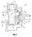
- Figure 1 illustrates a cross section of an exemplary embodiment of emission control module 5 with valve components packaged in a vertical stacked arrangement along a common axis 15.
- This vertical stacked configuration provides for, among other things, easy assembly of the valve components in a manufacturing process.
- a switch mechanism 10 for performing low level vacuum leak detection testing when the vehicle is not in operation.
- the switch mechanism 10 comprises a biased-open low vacuum switching element 30, such as a spring-biased diaphragm illustrated in Figure 1, arranged to engage an electrical connector 40.
- Low vacuum switch element 30 is biased open by flat spring element 35 as best shown in Figure 1.
- the low vacuum switch element 30 is arranged to overcome flat spring element 35 and translate to contact electrical connector 40 in response to a predetermined low vacuum condition generated by vehicle operation.
- Flat spring element 35 is calibrated such that upon exposure to a low vacuum condition threshold through carbon canister port 110, the low vacuum switch element 30 will engage the electrical connector 40 and thereby complete a circuit for low level leak test verification.
- the pattern of vacuum flow for low vacuum leak test verification is illustrated by arrow A in Figure 2. If the low vacuum condition is such that the biasing force of spring element 35 can not be overcome, switch element 30 will not contact electrical connector 40 and will be in an open position as best shown in Figure 1.
- the emission control apparatus further includes a high negative pressure valve 60 positioned relative to an atmospheric port 70 and carbon canister port 110.
- the carbon canister may be coupled to the integrity module or arranged in fluid communication with the integrity module via carbon canister port 110.
- High negative pressure valve 60 is arranged in conjunction with the low vacuum switch element 30 to allow for high vacuum leak detection testing, high vacuum regulation, and canister purging.
- High negative pressure valve 60 further includes a gravity biasing member 65 arranged to bias valve 60 to a closed position. It should be appreciated that the threshold to overcome flat spring element 35 in a low vacuum leak detection mode is less than that required to overcome high negative pressure valve 60 that is biased to a closed or sealed position by gravity biasing member 65.
- an engine purge valve (not shown) is operated to close a connection between the emission control apparatus 5 and an engine (not shown) to create a high vacuum condition in the evaporative emission system.
- high vacuum condition is above a predetermined high vacuum threshold
- high negative pressure valve 60 is in an open position.
- Stopping the vacuum draw causes the amount of vacuum to drop below the threshold of the high vacuum threshold of gravity biasing member 65 of high negative pressure valve 60 and thus allowing for it to close.
- the low vacuum switch element 30 As the vacuum bleeds down to a level below the low vacuum threshold of flat spring element 35, the low vacuum switch element 30 is arranged to disengage from the electrical connector 40 and open the circuit. The rate at which the vacuum bleeds down from the high vacuum threshold to a level that opens the circuit is measured and compared to a calibrated value for high vacuum leak test verification. Fluid flow distribution for the high vacuum leak test verification and regulation is shown by arrow B in Figure 3.
- emission control module 5 further includes a high positive pressure valve 80.
- High positive pressure valve 80 is operably connected to a carbon canister (not shown) at the canister interface port 110 and the atmosphere at atmospheric port 70 while bypassing the high negative pressure valve and the low vacuum switching element 30.
- High positive pressure valve 80 includes a gravity biasing member 85 and is arranged to provide positive pressure relief and regulation and refueling bypass if engine pressure exceeds a predetermined high positive pressure threshold of high positive pressure valve 80.
- a fluid flow pattern for positive pressure relief is shown by arrow C in Figure 4.
- high negative pressure valve 60 and associated gravity biasing member 65 as well as high positive pressure valve 80 and associated gravity biasing member 85 are sized with diameters such that they can not be incorrectly assembled. More specifically, both valves are circularly shaped and thus can be inserted into housing 25 along axis 15 in any rotational orientation. Valve 80 and biasing member 85 are larger in diameter than valve 60 and biasing member 65. Each valve and its associated member are also positioned in housing 25 in such a manner that an outer diameter of each valve and its associated biasing member is in very close proximity to chamber structure housing 25. Thus, high positive pressure valve 80 and biasing member 85 have a diameter too large to fit in the designated assembly position of high negative pressure valve 60 and associated biasing member 65.
Abstract
Description
- The present invention relates generally to evaporative emission control for a motor vehicle, and, more particularly, to an improved leak detection and control arrangement for an evaporative emission system of a motor vehicle.
- In a conventional evaporative emission system, an emission control device is utilized in connection with a charcoal canister to recover fuel vapor from a refueling event and selectively purge this fuel vapor from the charcoal canister into the engine. The emission control device is further utilized to perform leak detection tests to verify the integrity of the evaporative emission system and also provide pressure relief of the evaporative emission system. The emission control device is typically connected to an engine and a fuel tank and also includes a connection to the atmosphere. In general, conventional emission control devices provide control of various valves under specific engine operating conditions to perform system leak tests as well as system pressure relief. An example of such an evaporative emission system is disclosed in commonly owned
U.S. Patent No. 6,073,487 which is hereby incorporated by reference in its entirety. - While such conventional systems work for their intended purpose, packaging of numerous system components and solenoids undesirably increase cost and complexity. Thus, there is a need for an evaporative emission system that overcomes the aforementioned and other disadvantages.
- Accordingly, an evaporative emission control and leak detection system for a motor vehicle is provided. The system is in fluid communication with a fuel tank, an engine, and a carbon canister. The system includes an integrated valve module that is in fluid communication with the carbon canister and the atmosphere. The module is arranged to vent the system when exposed to predetermined high negative and positive pressure conditions. The module includes a switch mechanism having a calibrated spring that is arranged to bias the switch mechanism to an open position. The switch is operable to indicate when the system is in a low negative pressure condition. The module also includes a one-way high negative pressure valve coupled to a fluid passage between the carbon canister, the atmosphere and the switch, and a one-way high positive pressure valve coupled to a fluid passage between the carbon canister and the atmosphere that bypasses the high negative pressure valve and the switch. The high negative and high positive pressure valves are positioned in a stacked arrangement in the integrated valve module.
- Other aspects, features, and advantages of the present invention will become more fully apparent from the following detailed description of the preferred embodiment, the appended claims, and in the accompanying drawings in which:
- Figure 1 illustrates a cross sectional view of an exemplary embodiment of an integrity module in accordance with the present invention;
- Figure 2 illustrates a cross sectional view of the exemplary embodiment under a low vacuum condition with switch activation in accordance with the present invention;
- Figure 3 illustrates a cross sectional view of the exemplary embodiment under a high vacuum relief condition in accordance with the present invention; and
- Figure 4 illustrates a cross sectional view of the exemplary embodiment under a pressure relief and/or refueling bypass condition in accordance with the present invention.
- Referring now to the drawings, Figure 1 illustrates a cross section of an exemplary embodiment of emission control module 5 with valve components packaged in a vertical stacked arrangement along a
common axis 15. This vertical stacked configuration provides for, among other things, easy assembly of the valve components in a manufacturing process. - In accordance with one aspect of the present invention and referring to Figures 1 and 2, a
switch mechanism 10 is provided for performing low level vacuum leak detection testing when the vehicle is not in operation. Theswitch mechanism 10 comprises a biased-open lowvacuum switching element 30, such as a spring-biased diaphragm illustrated in Figure 1, arranged to engage anelectrical connector 40. Lowvacuum switch element 30 is biased open byflat spring element 35 as best shown in Figure 1. - In operation and referring to Figure 2, the low
vacuum switch element 30 is arranged to overcomeflat spring element 35 and translate to contactelectrical connector 40 in response to a predetermined low vacuum condition generated by vehicle operation.Flat spring element 35 is calibrated such that upon exposure to a low vacuum condition threshold throughcarbon canister port 110, the lowvacuum switch element 30 will engage theelectrical connector 40 and thereby complete a circuit for low level leak test verification. The pattern of vacuum flow for low vacuum leak test verification is illustrated by arrow A in Figure 2. If the low vacuum condition is such that the biasing force ofspring element 35 can not be overcome,switch element 30 will not contactelectrical connector 40 and will be in an open position as best shown in Figure 1. - In accordance with another aspect of the present invention, the emission control apparatus further includes a high
negative pressure valve 60 positioned relative to anatmospheric port 70 andcarbon canister port 110. It should be appreciated that the carbon canister may be coupled to the integrity module or arranged in fluid communication with the integrity module viacarbon canister port 110. Highnegative pressure valve 60 is arranged in conjunction with the lowvacuum switch element 30 to allow for high vacuum leak detection testing, high vacuum regulation, and canister purging. Highnegative pressure valve 60 further includes agravity biasing member 65 arranged to biasvalve 60 to a closed position. It should be appreciated that the threshold to overcomeflat spring element 35 in a low vacuum leak detection mode is less than that required to overcome highnegative pressure valve 60 that is biased to a closed or sealed position bygravity biasing member 65. - In operation and referring to Figure 3, when a high vacuum leak test is desired to be performed, an engine purge valve (not shown) is operated to close a connection between the emission control apparatus 5 and an engine (not shown) to create a high vacuum condition in the evaporative emission system. Initially, when the high vacuum condition is above a predetermined high vacuum threshold, high
negative pressure valve 60 is in an open position. Subsequently operating the purge valve to stop the vacuum draw thereby allows the high vacuum condition to start to bleed down. Stopping the vacuum draw causes the amount of vacuum to drop below the threshold of the high vacuum threshold ofgravity biasing member 65 of highnegative pressure valve 60 and thus allowing for it to close. As the vacuum bleeds down to a level below the low vacuum threshold offlat spring element 35, the lowvacuum switch element 30 is arranged to disengage from theelectrical connector 40 and open the circuit. The rate at which the vacuum bleeds down from the high vacuum threshold to a level that opens the circuit is measured and compared to a calibrated value for high vacuum leak test verification. Fluid flow distribution for the high vacuum leak test verification and regulation is shown by arrow B in Figure 3. - In accordance with another aspect of the present invention and referring to Figure 4, emission control module 5 further includes a high
positive pressure valve 80. Highpositive pressure valve 80 is operably connected to a carbon canister (not shown) at thecanister interface port 110 and the atmosphere atatmospheric port 70 while bypassing the high negative pressure valve and the lowvacuum switching element 30. Highpositive pressure valve 80 includes agravity biasing member 85 and is arranged to provide positive pressure relief and regulation and refueling bypass if engine pressure exceeds a predetermined high positive pressure threshold of highpositive pressure valve 80. A fluid flow pattern for positive pressure relief is shown by arrow C in Figure 4. - Incorporation of vacuum relief and regulation capability into the emission control apparatus provides for elimination of a separate, remotely packaged solenoid valve typically used in conventional evaporative emission control systems. In addition, by providing a low vacuum switch element having a calibrated flat spring in accordance with this invention, the need for a low negative pressure check valve is obviated thereby simplifying the module and assembly process.
- In addition, high
negative pressure valve 60 and associatedgravity biasing member 65 as well as highpositive pressure valve 80 and associatedgravity biasing member 85 are sized with diameters such that they can not be incorrectly assembled. More specifically, both valves are circularly shaped and thus can be inserted intohousing 25 alongaxis 15 in any rotational orientation. Valve 80 and biasingmember 85 are larger in diameter thanvalve 60 and biasingmember 65. Each valve and its associated member are also positioned inhousing 25 in such a manner that an outer diameter of each valve and its associated biasing member is in very close proximity to chamber structure housing 25. Thus, highpositive pressure valve 80 and biasingmember 85 have a diameter too large to fit in the designated assembly position of highnegative pressure valve 60 and associatedbiasing member 65.
Claims (10)
- An evaporative emission control and leak detection system for a motor vehicle, the system in fluid communication with emissions from a fuel tank, an engine and a carbon canister, the system comprising:an integrated valve module in fluid communication with the carbon canister and the atmosphere, and arranged to vent the system when exposed to predetermined high negative and positive pressure conditions, the module including:a switch mechanism operable to indicate when the system is in a low negative pressure condition, the switch mechanism including a spring for biasing the switch to an open position;a one-way high negative pressure valve coupled to a fluid passage between the carbon canister, the atmosphere and the switch; anda one-way high positive pressure valve coupled to a fluid passage between the carbon canister and the atmosphere that bypasses the high negative pressure valve and the switch;wherein the high negative and high positive pressure valves are positioned in a stacked arrangement in the integrated valve module.
- The system of claim 1, wherein the switch mechanism is arranged to provide low level system leak test verification, the switch mechanism biased to an open position unless a negative pressure exceeding a predetermined low negative pressure threshold is present in the system.
- The system of claim 1, wherein the module further comprises a chamber in fluid communication with the high negative pressure valve, the canister and the atmosphere, and wherein the switch mechanism is positioned within the chamber.
- The system of claim 1, wherein the switch mechanism further comprises a diaphragm member coupled to the spring and an electrical connector, the diaphragm member arranged to contact the electrical connector upon being exposed to a negative pressure condition sufficient to overcome a predetermined threshold of the spring.
- The system of claim 1, wherein the high negative pressure one-way valve includes a gravity biased valve member and is arranged to provide high negative system pressure relief and regulation, the high negative pressure valve biased to a closed position unless a negative pressure exceeding a predetermined high negative pressure threshold is present in the system.
- The system of claim 1, wherein the high positive pressure one-way valve includes a gravity-biased valve member and is arranged to provide high positive pressure system relief, the high positive pressure valve biased to a closed position unless a positive pressure exceeding a predetermined high positive pressure threshold is present in the system.
- The system of claim 1, wherein the high positive pressure one-way valve is further arranged to provide pressure relief for the system during refueling of the fuel tank.
- The system of claim 1, wherein the carbon canister is coupled to the integrated valve module.
- The system of claim 1, wherein the valves are non-interchangably positioned in a stacked arrangement in the integrated valve module.
- The system of claim 1, wherein the valves are non-interchangably positioned in a stacked arrangement along a common axis in the integrated valve module.
Applications Claiming Priority (1)
| Application Number | Priority Date | Filing Date | Title |
|---|---|---|---|
| US11/124,696 US7216636B2 (en) | 2005-05-09 | 2005-05-09 | Evaporative system integrity monitor |
Publications (3)
| Publication Number | Publication Date |
|---|---|
| EP1722093A2 true EP1722093A2 (en) | 2006-11-15 |
| EP1722093A3 EP1722093A3 (en) | 2010-01-13 |
| EP1722093B1 EP1722093B1 (en) | 2015-12-02 |
Family
ID=36088547
Family Applications (1)
| Application Number | Title | Priority Date | Filing Date |
|---|---|---|---|
| EP06003190.3A Expired - Fee Related EP1722093B1 (en) | 2005-05-09 | 2006-02-16 | Evaporative system integrity monitor |
Country Status (4)
| Country | Link |
|---|---|
| US (1) | US7216636B2 (en) |
| EP (1) | EP1722093B1 (en) |
| CN (1) | CN1862002B (en) |
| CA (1) | CA2536600C (en) |
Cited By (1)
| Publication number | Priority date | Publication date | Assignee | Title |
|---|---|---|---|---|
| EP2217801A2 (en) * | 2007-11-19 | 2010-08-18 | Mahle Technology Inc. | Vapor canister having integrated evaporative emission purge actuation monitoring system having fresh air filter |
Families Citing this family (9)
| Publication number | Priority date | Publication date | Assignee | Title |
|---|---|---|---|---|
| US7431022B1 (en) | 2007-07-24 | 2008-10-07 | Mahle Technology, Inc. | Evaporative emission canister purge actuation monitoring system |
| US20090126703A1 (en) * | 2007-11-19 | 2009-05-21 | Kevin Mulkeran | Vapor canister having integrated evaporative emission purge actuation monitoring system |
| US20090132147A1 (en) * | 2007-11-19 | 2009-05-21 | Hans Jensen | Evaporative emission canister purge actuation monitoring system having an integrated fresh air filter |
| GB2463478B (en) * | 2008-09-12 | 2011-12-21 | Ford Global Tech Llc | A vacuum decay testing method |
| CN102393279B (en) * | 2011-10-26 | 2013-11-20 | 中国南方航空工业(集团)有限公司 | Device for detecting sealing performance of engine |
| US8843265B2 (en) | 2012-04-23 | 2014-09-23 | Chrysler Group Llc | Turbo-charged engine purge flow monitor diagnostic |
| US9759166B2 (en) | 2015-09-09 | 2017-09-12 | Ford Global Technologies, Llc | Systems and methods for evaporative emissions testing |
| US10724923B2 (en) * | 2017-05-19 | 2020-07-28 | Hudson View Labs Inc. | Evaporative emissions control systems testing device |
| JP2020133396A (en) * | 2019-02-12 | 2020-08-31 | 愛三工業株式会社 | Canister for evaporated fuel processing device |
Citations (1)
| Publication number | Priority date | Publication date | Assignee | Title |
|---|---|---|---|---|
| US6073487A (en) | 1998-08-10 | 2000-06-13 | Chrysler Corporation | Evaporative system leak detection for an evaporative emission control system |
Family Cites Families (10)
| Publication number | Priority date | Publication date | Assignee | Title |
|---|---|---|---|---|
| US5383437A (en) * | 1992-12-23 | 1995-01-24 | Siemens Automotive Limited | Integrity confirmation of evaporative emission control system against leakage |
| CN2150346Y (en) * | 1993-03-04 | 1993-12-22 | 中国第一汽车集团公司长春汽车研究所 | Fuel-oil vaporization controlling device for gasoline vehicle |
| CN2200701Y (en) * | 1994-01-22 | 1995-06-14 | 朱宝泉 | Control device for fuel evaporation excreta of gasoline vehicle |
| US5437257A (en) * | 1994-02-28 | 1995-08-01 | General Motors Corporation | Evaporative emission control system with vent valve |
| US5474050A (en) * | 1995-01-13 | 1995-12-12 | Siemens Electric Limited | Leak detection pump with integral vent seal |
| CN2237729Y (en) * | 1995-12-27 | 1996-10-16 | 北京市通运节能技术开发公司 | Gasoline evaporation controller for automobile |
| CN2367525Y (en) * | 1999-04-22 | 2000-03-08 | 湖南首一国际工业有限公司 | Apparatus for recovering fuel-evaporation residue in oil-tank and waste-gas in crank case of motorcycle |
| US6474314B1 (en) * | 1999-11-19 | 2002-11-05 | Siemens Canada Limited | Fuel system with intergrated pressure management |
| US6823850B1 (en) * | 2003-09-16 | 2004-11-30 | Daimlerchrysler Corporation | Evaporative emission system integrity module |
| US6928991B2 (en) * | 2003-09-16 | 2005-08-16 | Daimlerchrysler Corporation | Evaporative emission system integrity module |
-
2005
- 2005-05-09 US US11/124,696 patent/US7216636B2/en active Active
-
2006
- 2006-02-15 CA CA2536600A patent/CA2536600C/en not_active Expired - Fee Related
- 2006-02-16 EP EP06003190.3A patent/EP1722093B1/en not_active Expired - Fee Related
- 2006-03-08 CN CN2006100588930A patent/CN1862002B/en not_active Expired - Fee Related
Patent Citations (1)
| Publication number | Priority date | Publication date | Assignee | Title |
|---|---|---|---|---|
| US6073487A (en) | 1998-08-10 | 2000-06-13 | Chrysler Corporation | Evaporative system leak detection for an evaporative emission control system |
Cited By (2)
| Publication number | Priority date | Publication date | Assignee | Title |
|---|---|---|---|---|
| EP2217801A2 (en) * | 2007-11-19 | 2010-08-18 | Mahle Technology Inc. | Vapor canister having integrated evaporative emission purge actuation monitoring system having fresh air filter |
| EP2217801A4 (en) * | 2007-11-19 | 2011-11-09 | Mahle Int Gmbh | Vapor canister having integrated evaporative emission purge actuation monitoring system having fresh air filter |
Also Published As
| Publication number | Publication date |
|---|---|
| CA2536600C (en) | 2013-09-17 |
| CN1862002B (en) | 2012-06-13 |
| CN1862002A (en) | 2006-11-15 |
| EP1722093A3 (en) | 2010-01-13 |
| CA2536600A1 (en) | 2006-11-09 |
| US20060249126A1 (en) | 2006-11-09 |
| US7216636B2 (en) | 2007-05-15 |
| EP1722093B1 (en) | 2015-12-02 |
Similar Documents
| Publication | Publication Date | Title |
|---|---|---|
| EP1722093B1 (en) | Evaporative system integrity monitor | |
| US7047950B2 (en) | Evaporative emission system integrity module | |
| CN106870209B (en) | Locking tank relief valve | |
| CN105857059B (en) | Valve assembly for high pressure fluid container | |
| US7856965B2 (en) | Natural vacuum leak detection device using diaphragm-seal mechanism | |
| US9631583B2 (en) | Latching mechanism for a fuel tank isolation valve assembly | |
| EP2841754B1 (en) | Turbocharged engine purge flow monitor diagnostic | |
| EP0955459A2 (en) | Air control valve assembly for fuel evaporative emission storage canister | |
| US6823850B1 (en) | Evaporative emission system integrity module | |
| US9732705B2 (en) | Latching canister vent valve | |
| RU2157911C2 (en) | Pump device for system maintaining evaporation of fuel and system using such device | |
| JP2004538407A (en) | Integrated pressure management system for fuel system | |
| US20150101677A1 (en) | Integrated pressure transducer in a latching valve | |
| US9683522B2 (en) | Fuel tank system and method for sensing perforation | |
| US20030000288A1 (en) | Sensor arrangement for an integrated pressure management apparatus | |
| EP2171248B1 (en) | Evaporative emission canister purge actuation monitoring system | |
| US6474314B1 (en) | Fuel system with intergrated pressure management | |
| KR20020093126A (en) | Integrated pressure management apparatus having electronic control circuit | |
| US6953027B2 (en) | Flow-through diaphragm for a fuel vapor pressure management apparatus | |
| JP4638319B2 (en) | Evaporative fuel emission suppression device for fuel tank | |
| WO2001086134A1 (en) | Connection between an integrated pressure management apparatus and a vapor collection canister | |
| EP1543236B1 (en) | Rationality testing for a fuel vapor pressure management apparatus | |
| JPH09119351A (en) | Evaporation fuel treatment device | |
| DE102014219958B4 (en) | Snap-canister vent valve |
Legal Events
| Date | Code | Title | Description |
|---|---|---|---|
| PUAI | Public reference made under article 153(3) epc to a published international application that has entered the european phase |
Free format text: ORIGINAL CODE: 0009012 |
|
| AK | Designated contracting states |
Kind code of ref document: A2 Designated state(s): AT BE BG CH CY CZ DE DK EE ES FI FR GB GR HU IE IS IT LI LT LU LV MC NL PL PT RO SE SI SK TR |
|
| AX | Request for extension of the european patent |
Extension state: AL BA HR MK YU |
|
| RAP1 | Party data changed (applicant data changed or rights of an application transferred) |
Owner name: CHRYSLER LLC |
|
| PUAL | Search report despatched |
Free format text: ORIGINAL CODE: 0009013 |
|
| AK | Designated contracting states |
Kind code of ref document: A3 Designated state(s): AT BE BG CH CY CZ DE DK EE ES FI FR GB GR HU IE IS IT LI LT LU LV MC NL PL PT RO SE SI SK TR |
|
| AX | Request for extension of the european patent |
Extension state: AL BA HR MK YU |
|
| RAP1 | Party data changed (applicant data changed or rights of an application transferred) |
Owner name: CHRYSLER GROUP LLC |
|
| 17P | Request for examination filed |
Effective date: 20100507 |
|
| 17Q | First examination report despatched |
Effective date: 20100610 |
|
| AKX | Designation fees paid |
Designated state(s): DE FR GB IT |
|
| GRAP | Despatch of communication of intention to grant a patent |
Free format text: ORIGINAL CODE: EPIDOSNIGR1 |
|
| INTG | Intention to grant announced |
Effective date: 20150619 |
|
| GRAS | Grant fee paid |
Free format text: ORIGINAL CODE: EPIDOSNIGR3 |
|
| GRAA | (expected) grant |
Free format text: ORIGINAL CODE: 0009210 |
|
| AK | Designated contracting states |
Kind code of ref document: B1 Designated state(s): DE FR GB IT |
|
| REG | Reference to a national code |
Ref country code: GB Ref legal event code: FG4D |
|
| REG | Reference to a national code |
Ref country code: DE Ref legal event code: R096 Ref document number: 602006047390 Country of ref document: DE |
|
| REG | Reference to a national code |
Ref country code: FR Ref legal event code: PLFP Year of fee payment: 11 |
|
| REG | Reference to a national code |
Ref country code: DE Ref legal event code: R097 Ref document number: 602006047390 Country of ref document: DE |
|
| PLBE | No opposition filed within time limit |
Free format text: ORIGINAL CODE: 0009261 |
|
| STAA | Information on the status of an ep patent application or granted ep patent |
Free format text: STATUS: NO OPPOSITION FILED WITHIN TIME LIMIT |
|
| 26N | No opposition filed |
Effective date: 20160905 |
|
| REG | Reference to a national code |
Ref country code: FR Ref legal event code: PLFP Year of fee payment: 12 |
|
| REG | Reference to a national code |
Ref country code: FR Ref legal event code: PLFP Year of fee payment: 13 |
|
| PGFP | Annual fee paid to national office [announced via postgrant information from national office to epo] |
Ref country code: IT Payment date: 20210323 Year of fee payment: 16 Ref country code: FR Payment date: 20210223 Year of fee payment: 16 |
|
| PGFP | Annual fee paid to national office [announced via postgrant information from national office to epo] |
Ref country code: GB Payment date: 20210225 Year of fee payment: 16 Ref country code: DE Payment date: 20210225 Year of fee payment: 16 |
|
| REG | Reference to a national code |
Ref country code: DE Ref legal event code: R119 Ref document number: 602006047390 Country of ref document: DE |
|
| GBPC | Gb: european patent ceased through non-payment of renewal fee |
Effective date: 20220216 |
|
| PG25 | Lapsed in a contracting state [announced via postgrant information from national office to epo] |
Ref country code: FR Free format text: LAPSE BECAUSE OF NON-PAYMENT OF DUE FEES Effective date: 20220228 |
|
| PG25 | Lapsed in a contracting state [announced via postgrant information from national office to epo] |
Ref country code: GB Free format text: LAPSE BECAUSE OF NON-PAYMENT OF DUE FEES Effective date: 20220216 Ref country code: DE Free format text: LAPSE BECAUSE OF NON-PAYMENT OF DUE FEES Effective date: 20220901 |
|
| PG25 | Lapsed in a contracting state [announced via postgrant information from national office to epo] |
Ref country code: IT Free format text: LAPSE BECAUSE OF NON-PAYMENT OF DUE FEES Effective date: 20220216 |