EP1721811A2 - Structure for fixing wheel arch molding - Google Patents
Structure for fixing wheel arch molding Download PDFInfo
- Publication number
- EP1721811A2 EP1721811A2 EP06252495A EP06252495A EP1721811A2 EP 1721811 A2 EP1721811 A2 EP 1721811A2 EP 06252495 A EP06252495 A EP 06252495A EP 06252495 A EP06252495 A EP 06252495A EP 1721811 A2 EP1721811 A2 EP 1721811A2
- Authority
- EP
- European Patent Office
- Prior art keywords
- wheel arch
- bumper
- molding
- arch molding
- wheel
- Prior art date
- Legal status (The legal status is an assumption and is not a legal conclusion. Google has not performed a legal analysis and makes no representation as to the accuracy of the status listed.)
- Granted
Links
- 238000000465 moulding Methods 0.000 title claims abstract description 57
- 210000000078 claw Anatomy 0.000 description 6
- 239000011248 coating agent Substances 0.000 description 5
- 238000000576 coating method Methods 0.000 description 5
- 230000002093 peripheral effect Effects 0.000 description 5
- 239000002184 metal Substances 0.000 description 3
- 229920003002 synthetic resin Polymers 0.000 description 3
- 239000000057 synthetic resin Substances 0.000 description 3
- 239000003086 colorant Substances 0.000 description 2
- 230000003247 decreasing effect Effects 0.000 description 2
- 238000000034 method Methods 0.000 description 2
- 230000000593 degrading effect Effects 0.000 description 1
- 239000000463 material Substances 0.000 description 1
- 238000010079 rubber tapping Methods 0.000 description 1
- 125000006850 spacer group Chemical group 0.000 description 1
Images





Classifications
-
- B—PERFORMING OPERATIONS; TRANSPORTING
- B62—LAND VEHICLES FOR TRAVELLING OTHERWISE THAN ON RAILS
- B62D—MOTOR VEHICLES; TRAILERS
- B62D25/00—Superstructure or monocoque structure sub-units; Parts or details thereof not otherwise provided for
- B62D25/08—Front or rear portions
- B62D25/16—Mud-guards or wings; Wheel cover panels
- B62D25/18—Parts or details thereof, e.g. mudguard flaps
-
- B—PERFORMING OPERATIONS; TRANSPORTING
- B60—VEHICLES IN GENERAL
- B60R—VEHICLES, VEHICLE FITTINGS, OR VEHICLE PARTS, NOT OTHERWISE PROVIDED FOR
- B60R13/00—Elements for body-finishing, identifying, or decorating; Arrangements or adaptations for advertising purposes
- B60R13/04—External Ornamental or guard strips; Ornamental inscriptive devices thereon
-
- B—PERFORMING OPERATIONS; TRANSPORTING
- B62—LAND VEHICLES FOR TRAVELLING OTHERWISE THAN ON RAILS
- B62D—MOTOR VEHICLES; TRAILERS
- B62D25/00—Superstructure or monocoque structure sub-units; Parts or details thereof not otherwise provided for
- B62D25/08—Front or rear portions
- B62D25/16—Mud-guards or wings; Wheel cover panels
- B62D25/161—Mud-guards made of non-conventional material, e.g. rubber, plastics
Definitions
- the present invention relates to a structure for fixing a wheel arch molding in which the wheel arch molding is fixed to an arc-shaped wheel arch formed at a bumper.
- Japanese Patent Application Laid-open No. 2000-103364 discloses a structure in which a wheel arch molding 5 to be mounted to a wheel arch (attachment surface 9) of a bumper side 3 is formed to be L-shaped in section, a protruding claw 16 provided on a back surface of a decorative face of the wheel arch molding 5, which faces outward from a vehicle body, is engaged in a mounting hole 25 provided in the attachment surface 9 of the bumper side 3, and a flange (abutment surface 13) which extends to an inside of the vehicle body from the decorative face is fixed to a mounting surface 12 of the bumper side 3 with a clip 15.
- the flange (abutment surface 13) which extends to the inside of the vehicle body from the decorative face of the wheel arch molding 5 is fixed to the mounting surface 12 of the bumper side 3 with the clip 15, and therefore has a problem that the width in a vehicle width direction of the flange becomes large in order to secure the attachment space for the clip 15, and the tread of a wheel is correspondingly limited to be small.
- the present invention has been achieved in view of the above circumstances, and has an object to fix a wheel arch molding to a wheel arch beautifully so that a gap is not generated between the wheel archmolding and the wheel arch while decreasing a dimension in the vehicle width direction of the wheel arch molding that is fixed to the wheel arch of the bumper.
- a structure for fixing a wheel arch molding in which a wheel arch molding is fixed to an arc-shaped wheel arch formed at a bumper, characterized in that a radially outer edge of the wheel arch molding is caused to abut on a step portion formed at a radially outer edge of the wheel arch, and a clip provided on a back surface of the wheel arch molding at an intermediate portion in a band width direction is engaged with the wheel arch, whereby a protruding portion formed at a radially inner edge of the wheel arch presses the back surface of the wheel arch molding.
- the rear bumper 11 in an embodiment corresponds to the bumper of the present invention.
- the protruding portion formed at the radially inner edge of the wheel arch presses the back surface of the wheel arch molding. Therefore, the protruding portion of the wheel arch becomes a fulcrum and the clips become a power point, whereby the radially outer edge of the wheel arch molding serving as a point of application closely contacts the step portion of the wheel arch to improve the appearance.
- a flange which protrudes inward in the vehicle width direction does not need to be formed at the radially inner edge of the wheel arch molding, and therefore the dimension in the vehicle width direction of the wheel arch molding is made small to be able to secure the tread of a wheel.
- a rear bumper 11 of an automobile is constructed by a coated upper bumper 12 and an uncoated lower bumper 13.
- the rear bumper 11 includes a main body part 14 which extends in a lateral direction along a vehicle body rear surface, and a pair of side parts 15 (only the left side part is shown in FIG. 1) which extend to the vehicle body front side from left and right opposite ends of the main body part 14.
- a rear portion of a wheel arch molding 17 which covers a wheel arch 16 of a rear wheel W is connected to the side part 15 of the rear bumper 11.
- An exhaust finisher 19 which decorates an outlet of an exhaust pipe 18 is provided at a position near a left end of the lower bumper 13.
- the upper bumper 12 and the lower bumper 13 are connected with a plurality of recess-protrusion engaging portions 21 disposed at predetermined intervals, and in the side part 15 of the rear bumper 11, the upper bumper 12 and the lower bumper 13 are positioned with a recess-protrusion engaging portion 22 at one spot and connected with one clip 23.
- the recess-protrusion engaging portion 21 which connects the upper bumper 12 and the lower bumper 13 in the main body part 14 of the rear bumper 11 is constructed by a locking claw 12c which protrudes downward from above into an opening 12b at an innermost side of a slit 12a which is formed in a lower edge of the upper bumper 12, and a locking hole 13b which is formed at a center of a rib 13a provided at an upper edge of the lower bumper 13 to protrude to the front side of the vehicle body.
- the locking claw 12c of the upper bumper 12 is elastically engaged in the locking hole 13b of the lower bumper 13 to achieve connection between the upper bumper 12 and the lower bumper 13 in the main body part 14 of the rear bumper 11.
- the recess-protrusion engaging portion 22 which connects the upper bumper 12 and the lower bumper 13 in the side part 15 of the rearbumper 11 is constructed by a rectangular locking hole 12e which is formed in a flange 12d (see FIG. 3) at a lower edge of the upper bumper 12, and a locking protrusion 13d rectangular in section which is provided to protrude upward in a flange 13c (see FIG. 3) at the upper edge of the lower bumper 13.
- the locking hole 12e and the locking protrusion 13d extend in a substantially longitudinal direction of the vehicle body.
- the upper bumper 12 and the lower bumper 13 can be positioned with each other by engaging the locking hole 12e and the locking protrusion 13d in the side part 15, and in this state, the upper bumper 12 and the lower bumper 13 are connected together by the clip 23. Since the locking hole 12e and the locking protrusion 13d extend in the longitudinal direction of the vehicle body, parallelism of the upper bumper 12 and the lower bumper 13 in the side part 15 is effectively secured to enhance the positioning accuracy. In addition, a large number of bolts and a large number of clips do not need to be used, thereby contributing to reduction in the number of components and the number of assembling steps.
- the wheel arch molding 17 is connected at a position near the rear portion to the wheel arch 16 of the upper bumper 12 with four clips 24, and a rear portion of the wheel arch molding 17 is connected to the wheel arch 16 of the lower bumper 13 with three clips 25 and one clip 26.
- an arc-shaped step portion 16a which is recessed inside the vehicle body is formed in a portion of the wheel arch 16, which corresponds to the front edge of the upper bumper 12, and the four clips 24 projectingly provided on the back surface of the wheel arch molding 17 engage with the upper bumper 12 in a state in which a radially outer edge of the wheel arch molding 17 abuts on the step portion 16a (see FIG. 11A).
- a protruding portion 16b projectingly provided at a radially inner edge of the wheel arch 16 abuts on a back surface of the wheel arch molding 17 so as to press the back surface of the wheel arch molding 17 with a fixing load applied by the clips 24.
- An arc-shaped step portion 16c which is recessed inside the vehicle body is formed at a portion of the wheel arch 16, which corresponds to the front edge of the lower bumper 13, and the three clips 25 projectingly provided on the inner surface of the wheel arch molding 17 engage with the lower bumper 13 in a state in which the radially outer edge of the wheel arch molding 17 abuts on the step portion 16c (see FIG. 11B). Further, a rear end of the wheel arch molding 17 is connected to the front edge of the lower bumper 13 with the one clip 26 which is inserted upward from below (see FIG. 8).
- the upper bumper 12 is fixed to the vehicle body 28 with respective two bolts 27 and 27 on the left and the right.
- a cup-shaped recessed portion 12g is formed in the upper bumper 12 in the vicinity of a fastening portion of each of the bolts 27, and the bolt 27 which penetrates through a bottom wall of the recessed portion 12g and the vehicle body 28 is screwed into a weld nut 29 and fastened.
- the recessed portion 12g of the upper bumper 12 is closed by a bolt hole cap 30.
- the bolt hole cap 30 is made of a synthetic resin which is the same as the material of the upper bumper 12, and two locking claws 30a and 30a projectingly provided on the back surface of the bolt hole cap 30 engage in two locking holes 12h and 12h formed in a side wall of the recessed portion 12g, whereby the bolt hole cap 30 is fixed to the upper bumper 12.
- the upper bumper 12 is a coated component, and the bolt hole caps 30 and 30 are also coated in the same color as the upper bumper 12. If the upper bumper 12 and the bolt hole caps 30 and 30 are separately coated, there is a fear of slightly different colors of them degrading the quality, and therefore the bolt hole caps 30 and 30 are simultaneously coated when the upper bumper 12 is coated.
- two sets of temporary support holes 12i and 12i are formed in the wheel arch 16 of the upper bumper 12 which is covered with the wheel arch molding 17 as shown in FIG. 12, and the locking claws 30a and 30a of the bolt hole cap 30 are engaged in the temporary support holes 12i and 12i to temporarily support the bolt hole cap 30 at the upper bumper 12.
- the bolt hole cap 30 is temporarily supported at the upper bumper 12 as shown in FIG. 12, the difference between the colors of the bolt hole cap 30 and the upper bumper 12 can be prevented, and the number of coating steps does not increase. If the bolt hole cap 30 is removed from the upper bumper 12 after the coating, the portion where the bolt hole cap 30 is mounted to the wheel arch 16 of the upper bumper 12 has no coating, but such a portion is the portion concealed by the wheel arch molding 17, providing no problem.
- the front end of the upper bumper 12 is fixed to a spacer 31 which is fixed to the vehicle body with a taping screw 32.
- the tapping screw 32 is covered with the wheel arch molding 17 to be invisible from outside.
- left and right opposite end portions of the lower edge of the lower bumper 13 are each connected to the vehicle body 28 with three clips 33 which are inserted upward from below.
- three clips 33 which are inserted upward from below.
- six clips 34 supported on an inner surface of a front portion of the wheel arch molding 17 engage with the wheel arch 16.
- the metal exhaust finisher 19 As shown in FIGS. 13 to 15, the metal exhaust finisher 19, a finisher holder 41 of a heat-resistant synthetic resin, and a metal exhaust guide member 42 are combined, and three bolts 43 which penetrate through three flanges 42a of the exhaust guide member 42, the finisher holder 41 and three mounting brackets 19a of the exhaust finisher 19 are screwed into weld nuts 44 which are provided on back surfaces of these mounting brackets 19a and fastened.
- the exhaust guide member 42, the finisher holder 41 and the exhaust finisher 19 which are thus integrated with the three bolts 43 are fastened together to the lower bumper 13 and the vehicle body 28 with the two clips 33 and 33 which penetrate through a mounting bracket 41a provided on an undersurface of the finisher holder 41 (see FIGS. 3 and 9).
- Two mounting brackets 41b and 41b which are provided on an upper surface of the finisher holder 41 are fixed to the upper bumper 12 with two clips 45 and 45 (see FIG. 4).
- an outlet opening portion of the exhaust pipe 18 is loosely inserted into the exhaust guide member 42 (see FIG. 13), and the exhaust finisher 19 is exposed from a triangular open flange 13f of the lower bumper 13 to improve the appearance (see FIG. 4).
- a triangular first positioning rib 41c, and six second positioning ribs 41d radially disposed with a predetermined gap along an outer periphery of the first positioning rib 41c are projectingly provided, and the open flange 13f of the lower bumper 13 is held between the first and second positioning ribs 41c and 41d with a gap therebetween.
- a triangular third positioning rib 41e which is provided at an inner periphery of the triangular first positioning rib 41c abuts on a step portion 19b on the front surface of the exhaust finisher 19 toposition the exhaust finisher 19 in the longitudinal direction.
- the exhaust finisher 19 has an outer peripheral flange 19c and an inner peripheral flange 19d which extend toward the front side of the vehicle body, and the outer peripheral flange 19c closely contacts an inner peripheral surface of the first positioning rib 41c of the finisher holder 41 to be positioned.
- a gap between the open flange 13f of the rear bumper 11 and the outer peripheral flange 19c of the exhaust finisher 19 is kept constant by the first positioning rib 41c of the finisher holder 41, and therefore, the gap can be evenly kept over the entire periphery to improve the appearance.
- the heat of the metal exhaust finisher 19 which is at a high temperature due to contact with an exhaust gas can be shielded by the rib 41c of the finisher holder 41 made of the heat-resistant synthetic resin and the gap to make it difficult for the heat to reach the open flange 13f of the rear bumper 11.
- the lower bumper 13 is brought close to the upper bumper 12 from behind, the ribs 13a provided at the upper edge of the lower bumper 13 are inserted into the slits 12a provided in the lower edge of the upper bumper 12, and the locking claws 12c of the upper bumper 12 are engaged in the locking holes 13b of the lower bumper 13 (see FIG. 6).
- the locking protrusion 13d provided on the upper surface of the flange 13c of the lower bumper 13 is engaged in the locking hole 12e provided in the flange 12d of the upper bumper 12, and the flange 13c of the lower bumper 13 and the flange 12d of the upper bumper 12 are connected together by the clip 23 (see FIG. 7).
- the exhaust guide member 42, the finisher holder 41 and the exhaust finisher 19 which are integrated with the three bolts 43 are fixed to the lower bumper 13 with the two clips 33 and 33, and are fixed to the upper bumper 12 with the two clips 45 and 45 (see FIG. 13).
- the rigidity of the rear bumper 11 can be enhanced.
- the rear bumper 11 which has been completely assembled has its lower bumper 13 fixed to the vehicle body 28 with the clips 33 (see FIG. 9), and has its upper bumper 12 fixed to the vehicle body 28 with the respective two bolts 27 and 27 on the left and the right (see FIG. 10).
- the wheel arch molding 17 is attached so as to cover the substantially semicircular wheel arch 16 which is defined by the vehicle body 28 and the rear bumper 11.
- the wheel arch molding 17 is connected at the position near the rear portion to the wheel arch 16 of the upper bumper 12 with the four clips 24, then the rear portion of the wheel arch molding 17 is connected to the wheel arch 16 of the lower bumper 13 with the three clips 25 and the one clip 26, and as shown in FIGS. 3 and 11D, the six clips 34 which are supported on the inner surface of the front portion of the wheel arch molding 17 are engaged with the vehicle body 28.
- the wheel archmolding 17 is a substantiallyplate-shaped member and does not include a mounting flange which extends to the inside of the vehicle body, the dimension in the vehicle width direction of the wheel arch molding 17 can be decreased to avoid interference with the wheel, and a sufficient tread of the wheel can be secured.
- the wheel arch molding 17 on the rear side is described, but the present invention is also applicable to the wheel arch molding 17 on the front side.
Landscapes
- Engineering & Computer Science (AREA)
- Mechanical Engineering (AREA)
- Chemical & Material Sciences (AREA)
- Combustion & Propulsion (AREA)
- Transportation (AREA)
- Vehicle Interior And Exterior Ornaments, Soundproofing, And Insulation (AREA)
- Body Structure For Vehicles (AREA)
Abstract
Description
- The present invention relates to a structure for fixing a wheel arch molding in which the wheel arch molding is fixed to an arc-shaped wheel arch formed at a bumper.
-
Japanese Patent Application Laid-open No. 2000-103364 wheel arch molding 5 to be mounted to a wheel arch (attachment surface 9) of abumper side 3 is formed to be L-shaped in section, a protrudingclaw 16 provided on a back surface of a decorative face of thewheel arch molding 5, which faces outward from a vehicle body, is engaged in amounting hole 25 provided in the attachment surface 9 of thebumper side 3, and a flange (abutment surface 13) which extends to an inside of the vehicle body from the decorative face is fixed to amounting surface 12 of thebumper side 3 with aclip 15. - In the structure described in
Japanese Patent Application Laid-open No. 2000-103364 wheel arch molding 5 is fixed to themounting surface 12 of thebumper side 3 with theclip 15, and therefore has a problem that the width in a vehicle width direction of the flange becomes large in order to secure the attachment space for theclip 15, and the tread of a wheel is correspondingly limited to be small. - The present invention has been achieved in view of the above circumstances, and has an object to fix a wheel arch molding to a wheel arch beautifully so that a gap is not generated between the wheel archmolding and the wheel arch while decreasing a dimension in the vehicle width direction of the wheel arch molding that is fixed to the wheel arch of the bumper.
- According to the present invention, there is provided a structure for fixing a wheel arch molding, in which a wheel arch molding is fixed to an arc-shaped wheel arch formed at a bumper, characterized in that a radially outer edge of the wheel arch molding is caused to abut on a step portion formed at a radially outer edge of the wheel arch, and a clip provided on a back surface of the wheel arch molding at an intermediate portion in a band width direction is engaged with the wheel arch, whereby a protruding portion formed at a radially inner edge of the wheel arch presses the back surface of the wheel arch molding.
- The
rear bumper 11 in an embodiment corresponds to the bumper of the present invention. - With the arrangement of the present invention, when the radially outer edge of the wheel arch molding is caused to abut on the step portion formed at the radially outer edge of the wheel arch, and the clip provided on the back surface of the wheel arch molding at an intermediate portion in the band width direction is engaged with the wheel arch, the protruding portion formed at the radially inner edge of the wheel arch presses the back surface of the wheel arch molding. Therefore, the protruding portion of the wheel arch becomes a fulcrum and the clips become a power point, whereby the radially outer edge of the wheel arch molding serving as a point of application closely contacts the step portion of the wheel arch to improve the appearance. In addition, in order to fix the wheel arch molding to the bumper, a flange which protrudes inward in the vehicle width direction does not need to be formed at the radially inner edge of the wheel arch molding, and therefore the dimension in the vehicle width direction of the wheel arch molding is made small to be able to secure the tread of a wheel.
- The above-mentioned object, other objects, characteristics and advantages of the present invention will become apparent from a preferred embodiment, which will be described in detail below by way of example only and with reference to the attached drawings, in which :
- FIG. 1 is a perspective view of a left half part of a rear bumper;
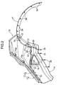
- FIG. 2 is a view seen in the direction of an
arrow 2 in FIG. 1; - FIG. 3 is an exploded perspective view corresponding to FIG. 2;
- FIG. 4 is a view seen in the direction of an arrow 4 in FIG. 1;
- FIG. 5 is a view seen in the direction of an
arrow 5 in FIG. 1; - FIG. 6 is an enlarged sectional view taken on a line 6-6 in FIG. 3;
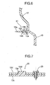
- FIG. 7 is an enlarged sectional view taken on a line 7-7 in FIG. 3;
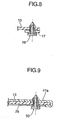
- FIG. 8 is an enlarged sectional view taken on a line 8-8 in FIG. 3;
- FIG. 9 is an enlarged sectional view taken on a line 9-9 in FIG. 3;
- FIG. 10 is an enlarged sectional view taken on a line 10-10 in FIG. 4;
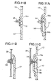
- FIGS. 11 A to 11D are enlarged sectional views of the respective parts in FIG. 5;
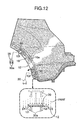
- FIG. 12 is an explanatory view of an operation at the time of coating a bolt hole cap;
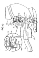
- FIG. 13 is an enlarged sectional view taken on a line 13-13 in FIG. 4;
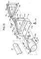
- FIG. 14 is a sectional view taken on a line 14-14 in FIG. 13; and FIG. 15 is an exploded perspective view of a periphery of an exhaust finisher.
- As shown in FIG. 1, a
rear bumper 11 of an automobile is constructed by a coatedupper bumper 12 and an uncoatedlower bumper 13. Therear bumper 11 includes amain body part 14 which extends in a lateral direction along a vehicle body rear surface, and a pair of side parts 15 (only the left side part is shown in FIG. 1) which extend to the vehicle body front side from left and right opposite ends of themain body part 14. A rear portion of awheel arch molding 17 which covers awheel arch 16 of a rear wheel W is connected to theside part 15 of therear bumper 11. Anexhaust finisher 19 which decorates an outlet of anexhaust pipe 18 is provided at a position near a left end of thelower bumper 13. - As shown in FIGS. 2 and 3, in the
main body part 14 of therear bumper 11, theupper bumper 12 and thelower bumper 13 are connected with a plurality of recess-protrusion engaging portions 21 disposed at predetermined intervals, and in theside part 15 of therear bumper 11, theupper bumper 12 and thelower bumper 13 are positioned with a recess-protrusion engaging portion 22 at one spot and connected with oneclip 23. - As is obvious from FIG. 6, the recess-
protrusion engaging portion 21 which connects theupper bumper 12 and thelower bumper 13 in themain body part 14 of therear bumper 11 is constructed by alocking claw 12c which protrudes downward from above into an opening 12b at an innermost side of aslit 12a which is formed in a lower edge of theupper bumper 12, and alocking hole 13b which is formed at a center of arib 13a provided at an upper edge of thelower bumper 13 to protrude to the front side of the vehicle body. Accordingly, when thelower bumper 13 is moved to the front side of the vehicle body relatively to theupper bumper 12, and therib 13a of thelower bumper 13 is inserted into the opening 12b of theslit 12a of theupper bumper 12, thelocking claw 12c of theupper bumper 12 is elastically engaged in thelocking hole 13b of thelower bumper 13 to achieve connection between theupper bumper 12 and thelower bumper 13 in themain body part 14 of therear bumper 11. - As is obvious from FIGS. 2, 3 and 7, the recess-
protrusion engaging portion 22 which connects theupper bumper 12 and thelower bumper 13 in theside part 15 of therearbumper 11 is constructed by arectangular locking hole 12e which is formed in aflange 12d (see FIG. 3) at a lower edge of theupper bumper 12, and alocking protrusion 13d rectangular in section which is provided to protrude upward in aflange 13c (see FIG. 3) at the upper edge of thelower bumper 13. Thelocking hole 12e and thelocking protrusion 13d extend in a substantially longitudinal direction of the vehicle body. - Accordingly, when the
lower bumper 13 is moved to the front side of the vehicle body relatively to theupper bumper 12 to connect themain body part 14, theupper bumper 12 and thelower bumper 13 can be positioned with each other by engaging thelocking hole 12e and thelocking protrusion 13d in theside part 15, and in this state, theupper bumper 12 and thelower bumper 13 are connected together by theclip 23. Since thelocking hole 12e and thelocking protrusion 13d extend in the longitudinal direction of the vehicle body, parallelism of theupper bumper 12 and thelower bumper 13 in theside part 15 is effectively secured to enhance the positioning accuracy. In addition, a large number of bolts and a large number of clips do not need to be used, thereby contributing to reduction in the number of components and the number of assembling steps. - As shown in FIGS. 2, 3 and 5, the
wheel arch molding 17 is connected at a position near the rear portion to thewheel arch 16 of theupper bumper 12 with fourclips 24, and a rear portion of thewheel arch molding 17 is connected to thewheel arch 16 of thelower bumper 13 with threeclips 25 and oneclip 26. - Namely, an arc-
shaped step portion 16a which is recessed inside the vehicle body is formed in a portion of thewheel arch 16, which corresponds to the front edge of theupper bumper 12, and the fourclips 24 projectingly provided on the back surface of thewheel arch molding 17 engage with theupper bumper 12 in a state in which a radially outer edge of the wheel arch molding 17 abuts on thestep portion 16a (see FIG. 11A). At this time, a protrudingportion 16b projectingly provided at a radially inner edge of thewheel arch 16 abuts on a back surface of thewheel arch molding 17 so as to press the back surface of thewheel arch molding 17 with a fixing load applied by theclips 24. - An arc-shaped step portion 16c which is recessed inside the vehicle body is formed at a portion of the
wheel arch 16, which corresponds to the front edge of thelower bumper 13, and the threeclips 25 projectingly provided on the inner surface of thewheel arch molding 17 engage with thelower bumper 13 in a state in which the radially outer edge of the wheel arch molding 17 abuts on the step portion 16c (see FIG. 11B). Further, a rear end of thewheel arch molding 17 is connected to the front edge of thelower bumper 13 with the oneclip 26 which is inserted upward from below (see FIG. 8). - As shown in FIGS. 3, 4 and 10, the
upper bumper 12 is fixed to thevehicle body 28 with respective twobolts recessed portion 12g is formed in theupper bumper 12 in the vicinity of a fastening portion of each of thebolts 27, and thebolt 27 which penetrates through a bottom wall of the recessedportion 12g and thevehicle body 28 is screwed into aweld nut 29 and fastened. In order to conceal a head of thebolt 27, therecessed portion 12g of theupper bumper 12 is closed by abolt hole cap 30. Thebolt hole cap 30 is made of a synthetic resin which is the same as the material of theupper bumper 12, and twolocking claws bolt hole cap 30 engage in twolocking holes portion 12g, whereby thebolt hole cap 30 is fixed to theupper bumper 12. - The
upper bumper 12 is a coated component, and thebolt hole caps upper bumper 12. If theupper bumper 12 and thebolt hole caps bolt hole caps upper bumper 12 is coated. For this purpose, two sets oftemporary support holes wheel arch 16 of theupper bumper 12 which is covered with thewheel arch molding 17 as shown in FIG. 12, and thelocking claws bolt hole cap 30 are engaged in thetemporary support holes bolt hole cap 30 at theupper bumper 12. - Accordingly, if coating is applied simultaneously in a state in which the
bolt hole cap 30 is temporarily supported at theupper bumper 12 as shown in FIG. 12, the difference between the colors of thebolt hole cap 30 and theupper bumper 12 can be prevented, and the number of coating steps does not increase. If thebolt hole cap 30 is removed from theupper bumper 12 after the coating, the portion where thebolt hole cap 30 is mounted to thewheel arch 16 of theupper bumper 12 has no coating, but such a portion is the portion concealed by thewheel arch molding 17, providing no problem. - As shown in FIGS. 3, 5 and 11C, the front end of the
upper bumper 12 is fixed to aspacer 31 which is fixed to the vehicle body with ataping screw 32. The tappingscrew 32 is covered with thewheel arch molding 17 to be invisible from outside. - As shown in FIGS. 2, 3 and 9, left and right opposite end portions of the lower edge of the
lower bumper 13 are each connected to thevehicle body 28 with threeclips 33 which are inserted upward from below. As shown in FIGS. 3 and 11D, in order to fix thewheel arch molding 17 to thewheel arch 16 of thevehicle body 28, sixclips 34 supported on an inner surface of a front portion of thewheel arch molding 17 engage with thewheel arch 16. - As shown in FIGS. 13 to 15, the
metal exhaust finisher 19, afinisher holder 41 of a heat-resistant synthetic resin, and a metalexhaust guide member 42 are combined, and threebolts 43 which penetrate through threeflanges 42a of theexhaust guide member 42, thefinisher holder 41 and threemounting brackets 19a of theexhaust finisher 19 are screwed intoweld nuts 44 which are provided on back surfaces of thesemounting brackets 19a and fastened. - The
exhaust guide member 42, thefinisher holder 41 and theexhaust finisher 19 which are thus integrated with the threebolts 43 are fastened together to thelower bumper 13 and thevehicle body 28 with the twoclips mounting bracket 41a provided on an undersurface of the finisher holder 41 (see FIGS. 3 and 9). Twomounting brackets finisher holder 41 are fixed to theupper bumper 12 with twoclips 45 and 45 (see FIG. 4). In this state, an outlet opening portion of theexhaust pipe 18 is loosely inserted into the exhaust guide member 42 (see FIG. 13), and theexhaust finisher 19 is exposed from a triangularopen flange 13f of thelower bumper 13 to improve the appearance (see FIG. 4). - On a rear surface of the
finisher holder 41, a triangularfirst positioning rib 41c, and sixsecond positioning ribs 41d radially disposed with a predetermined gap along an outer periphery of thefirst positioning rib 41c are projectingly provided, and theopen flange 13f of thelower bumper 13 is held between the first andsecond positioning ribs third positioning rib 41e which is provided at an inner periphery of the triangularfirst positioning rib 41c abuts on astep portion 19b on the front surface of theexhaust finisher 19 toposition theexhaust finisher 19 in the longitudinal direction. Theexhaust finisher 19 has an outerperipheral flange 19c and an innerperipheral flange 19d which extend toward the front side of the vehicle body, and the outerperipheral flange 19c closely contacts an inner peripheral surface of thefirst positioning rib 41c of thefinisher holder 41 to be positioned. - A gap between the
open flange 13f of therear bumper 11 and the outerperipheral flange 19c of theexhaust finisher 19 is kept constant by thefirst positioning rib 41c of thefinisher holder 41, and therefore, the gap can be evenly kept over the entire periphery to improve the appearance. In addition, the heat of themetal exhaust finisher 19 which is at a high temperature due to contact with an exhaust gas can be shielded by therib 41c of thefinisher holder 41 made of the heat-resistant synthetic resin and the gap to make it difficult for the heat to reach theopen flange 13f of therear bumper 11. - Next, an assembly procedure of the
rear bumper 11 will be described. - First, in order to integrally connect the
upper bumper 12 and thelower bumper 13 in themain body part 14, thelower bumper 13 is brought close to theupper bumper 12 from behind, theribs 13a provided at the upper edge of thelower bumper 13 are inserted into theslits 12a provided in the lower edge of theupper bumper 12, and the lockingclaws 12c of theupper bumper 12 are engaged in the locking holes 13b of the lower bumper 13 (see FIG. 6). - To integrally connect the
upper bumper 12 and thelower bumper 13 in each of theside parts 15 simultaneously with the above procedure, the lockingprotrusion 13d provided on the upper surface of theflange 13c of thelower bumper 13 is engaged in thelocking hole 12e provided in theflange 12d of theupper bumper 12, and theflange 13c of thelower bumper 13 and theflange 12d of theupper bumper 12 are connected together by the clip 23 (see FIG. 7). - Subsequently, the
exhaust guide member 42, thefinisher holder 41 and theexhaust finisher 19 which are integrated with the threebolts 43 are fixed to thelower bumper 13 with the twoclips upper bumper 12 with the twoclips 45 and 45 (see FIG. 13). By integrating theupper bumper 12 and thelower bumper 13 via thefinisher holder 41 in this way, the rigidity of therear bumper 11 can be enhanced. - The
rear bumper 11 which has been completely assembled has itslower bumper 13 fixed to thevehicle body 28 with the clips 33 (see FIG. 9), and has itsupper bumper 12 fixed to thevehicle body 28 with the respective twobolts - When the
rear bumper 11 is fixed to the vehicle body as described above, thewheel arch molding 17 is attached so as to cover the substantiallysemicircular wheel arch 16 which is defined by thevehicle body 28 and therear bumper 11. - Namely, as shown in FIGS. 2, 3 and 5, the
wheel arch molding 17 is connected at the position near the rear portion to thewheel arch 16 of theupper bumper 12 with the fourclips 24, then the rear portion of thewheel arch molding 17 is connected to thewheel arch 16 of thelower bumper 13 with the threeclips 25 and the oneclip 26, and as shown in FIGS. 3 and 11D, the sixclips 34 which are supported on the inner surface of the front portion of thewheel arch molding 17 are engaged with thevehicle body 28. - As is obvious from FIG. 11A, when the
wheel arch molding 17 is connected to thewheel arch 16 of theupper bumper 12 with theclips 24, the protrudingportion 16b projectingly provided at the radially inner edge of thewheel arch 16 becomes a fulcrum, theclips 24 become a power point, and the radially outer edge of thewheel arch molding 17, which is a point of application, is caused to closely contact thestep portion 16a of thewheel arch 16. Therefore, a gap is prevented from generating between thewheel arch molding 17 and thewheel arch 16 to improve the appearance. - Since the
wheel archmolding 17 is a substantiallyplate-shaped member and does not include a mounting flange which extends to the inside of the vehicle body, the dimension in the vehicle width direction of thewheel arch molding 17 can be decreased to avoid interference with the wheel, and a sufficient tread of the wheel can be secured. - The embodiment of the present invention has been described above, but the present invention is not limited to the above described embodiment, and various design changes can be made without departing from the subject matter of the present invention.
- For example, in the embodiment, the
wheel arch molding 17 on the rear side is described, but the present invention is also applicable to thewheel arch molding 17 on the front side.
Claims (1)
- A structure for fixing a wheel arch molding, in which a wheel arch molding (17) is fixed to an arc-shaped wheel arch (16) formed at a bumper (11),
characterized in that a radially outer edge of the wheel arch molding (17) is caused to abut on a step portion (16a) formed at a radially outer edge of the wheel arch (16), and a clip (24) provided on a back surface of the wheel arch molding (17) at an intermediate portion in a band width direction is engaged with the wheel arch (16), whereby a protruding portion (16b) formed at a radially inner edge of the wheel arch (16) presses the back surface of the wheel arch molding (17).
Applications Claiming Priority (1)
| Application Number | Priority Date | Filing Date | Title |
|---|---|---|---|
| JP2005140544A JP4234113B2 (en) | 2005-05-13 | 2005-05-13 | Fixed structure of wheel arch molding |
Publications (3)
| Publication Number | Publication Date |
|---|---|
| EP1721811A2 true EP1721811A2 (en) | 2006-11-15 |
| EP1721811A3 EP1721811A3 (en) | 2007-08-15 |
| EP1721811B1 EP1721811B1 (en) | 2009-01-28 |
Family
ID=36593039
Family Applications (1)
| Application Number | Title | Priority Date | Filing Date |
|---|---|---|---|
| EP20060252495 Ceased EP1721811B1 (en) | 2005-05-13 | 2006-05-12 | Structure for fixing wheel arch molding |
Country Status (4)
| Country | Link |
|---|---|
| EP (1) | EP1721811B1 (en) |
| JP (1) | JP4234113B2 (en) |
| CN (1) | CN100400338C (en) |
| DE (1) | DE602006005021D1 (en) |
Cited By (9)
| Publication number | Priority date | Publication date | Assignee | Title |
|---|---|---|---|---|
| EP2080693A1 (en) * | 2008-01-17 | 2009-07-22 | Peugeot Citroën Automobiles S.A. | Device for reinforcing the side of an automobile body |
| EP2423080A1 (en) * | 2010-08-27 | 2012-02-29 | Honda Motor Co., Ltd. | Wheel arch structure and assembly method of the same |
| FR3021596A1 (en) * | 2014-06-02 | 2015-12-04 | Renault Sas | BODY ARRANGEMENT OF A MOTOR VEHICLE COMPRISING A FICTIONAL EXHAUST CANNULA |
| CN107618576A (en) * | 2017-10-18 | 2018-01-23 | 洛阳北方易初摩托车有限公司 | Front part of vehicle working of plastics bridging arrangement |
| CN109435683A (en) * | 2018-10-31 | 2019-03-08 | 宁波中骏森驰汽车零部件股份有限公司 | A kind of automobile tail gate exhaust pipe |
| FR3089480A1 (en) * | 2018-12-10 | 2020-06-12 | Psa Automobiles Sa | Fender flange for covering a wheel arch of a motor vehicle, and motor vehicle incorporating it |
| FR3126391A1 (en) * | 2021-08-26 | 2023-03-03 | Psa Automobiles Sa | VEHICLE BODYWORK ELEMENT, WITH RIGIDIFIED RIM RECEPTION ZONE |
| DE102023125872A1 (en) | 2023-09-25 | 2025-01-09 | Dr. Ing. H.C. F. Porsche Aktiengesellschaft | Method for producing a wheel arch cover |
| FR3153301A1 (en) * | 2023-09-27 | 2025-03-28 | Psa Automobiles Sa | MOTOR VEHICLE BUMPER WITH A RIGIDIFIED HUB CAP MOUNTING AREA |
Families Citing this family (8)
| Publication number | Priority date | Publication date | Assignee | Title |
|---|---|---|---|---|
| DE102009042845B4 (en) | 2009-09-24 | 2019-02-14 | Dr. Ing. H.C. F. Porsche Aktiengesellschaft | clip |
| JP5554638B2 (en) * | 2010-06-11 | 2014-07-23 | 本田技研工業株式会社 | Internal combustion engine |
| JP6020240B2 (en) * | 2013-02-18 | 2016-11-02 | マツダ株式会社 | Vehicle side body structure |
| CN103112406B (en) * | 2013-03-18 | 2015-06-24 | 湖南南车时代电动汽车股份有限公司 | Wheel-arch decoration aluminum section bar for passenger car, and manufacturing and mounting process of section bar |
| DE102014105201A1 (en) * | 2014-04-11 | 2015-10-15 | Dr. Ing. H.C. F. Porsche Aktiengesellschaft | motor vehicle |
| JP6414741B2 (en) * | 2014-11-14 | 2018-10-31 | 三菱自動車工業株式会社 | Front over fender mounting structure and mounting method |
| WO2016181534A1 (en) * | 2015-05-13 | 2016-11-17 | 本田技研工業株式会社 | Vehicle exterior component structure |
| FR3159788A1 (en) * | 2024-02-29 | 2025-09-05 | Stellantis Auto Sas | Multi-function automotive vehicle rear bumper skin reinforcement |
Citations (1)
| Publication number | Priority date | Publication date | Assignee | Title |
|---|---|---|---|---|
| JP2000103364A (en) | 1998-09-30 | 2000-04-11 | Suzuki Motor Corp | Arch Mall Mounting Structure |
Family Cites Families (5)
| Publication number | Priority date | Publication date | Assignee | Title |
|---|---|---|---|---|
| JPS6157471A (en) * | 1984-08-29 | 1986-03-24 | Nissan Motor Co Ltd | Ornamental member setting structure in fender opening part |
| JP3487947B2 (en) * | 1995-02-21 | 2004-01-19 | 日野自動車株式会社 | Overfender mounting structure |
| US6205642B1 (en) * | 1999-05-28 | 2001-03-27 | General Motors Corporation | Method of mounting a body side molding |
| JP4099644B2 (en) * | 2002-04-18 | 2008-06-11 | スズキ株式会社 | Front bumper mounting structure |
| JP3850813B2 (en) * | 2003-06-23 | 2006-11-29 | 東海興業株式会社 | Bumpers spoiler and its mounting structure |
-
2005
- 2005-05-13 JP JP2005140544A patent/JP4234113B2/en not_active Expired - Fee Related
-
2006
- 2006-05-12 CN CNB2006100802370A patent/CN100400338C/en not_active Expired - Fee Related
- 2006-05-12 DE DE200660005021 patent/DE602006005021D1/en active Active
- 2006-05-12 EP EP20060252495 patent/EP1721811B1/en not_active Ceased
Patent Citations (1)
| Publication number | Priority date | Publication date | Assignee | Title |
|---|---|---|---|---|
| JP2000103364A (en) | 1998-09-30 | 2000-04-11 | Suzuki Motor Corp | Arch Mall Mounting Structure |
Cited By (13)
| Publication number | Priority date | Publication date | Assignee | Title |
|---|---|---|---|---|
| EP2080693A1 (en) * | 2008-01-17 | 2009-07-22 | Peugeot Citroën Automobiles S.A. | Device for reinforcing the side of an automobile body |
| FR2926523A1 (en) * | 2008-01-17 | 2009-07-24 | Peugeot Citroen Automobiles Sa | DEVICE FOR REPRESSING THE BODY SIDE OF A MOTOR VEHICLE |
| EP2423080A1 (en) * | 2010-08-27 | 2012-02-29 | Honda Motor Co., Ltd. | Wheel arch structure and assembly method of the same |
| FR3021596A1 (en) * | 2014-06-02 | 2015-12-04 | Renault Sas | BODY ARRANGEMENT OF A MOTOR VEHICLE COMPRISING A FICTIONAL EXHAUST CANNULA |
| WO2016001496A1 (en) * | 2014-06-02 | 2016-01-07 | Renault S.A.S. | Motor vehicle body arrangement comprising a dummy exhaust pipe |
| CN107618576A (en) * | 2017-10-18 | 2018-01-23 | 洛阳北方易初摩托车有限公司 | Front part of vehicle working of plastics bridging arrangement |
| CN109435683A (en) * | 2018-10-31 | 2019-03-08 | 宁波中骏森驰汽车零部件股份有限公司 | A kind of automobile tail gate exhaust pipe |
| FR3089480A1 (en) * | 2018-12-10 | 2020-06-12 | Psa Automobiles Sa | Fender flange for covering a wheel arch of a motor vehicle, and motor vehicle incorporating it |
| WO2020120856A1 (en) * | 2018-12-10 | 2020-06-18 | Psa Automobiles Sa | Mudguard rebate for the trim of a wheel-housing of a motor vehicle, and motor vehicle incorporating it |
| FR3126391A1 (en) * | 2021-08-26 | 2023-03-03 | Psa Automobiles Sa | VEHICLE BODYWORK ELEMENT, WITH RIGIDIFIED RIM RECEPTION ZONE |
| DE102023125872A1 (en) | 2023-09-25 | 2025-01-09 | Dr. Ing. H.C. F. Porsche Aktiengesellschaft | Method for producing a wheel arch cover |
| FR3153301A1 (en) * | 2023-09-27 | 2025-03-28 | Psa Automobiles Sa | MOTOR VEHICLE BUMPER WITH A RIGIDIFIED HUB CAP MOUNTING AREA |
| WO2025068642A1 (en) * | 2023-09-27 | 2025-04-03 | Stellantis Auto Sas | Motor vehicle bumper with stiffened trim attachment area |
Also Published As
| Publication number | Publication date |
|---|---|
| JP2006315552A (en) | 2006-11-24 |
| EP1721811B1 (en) | 2009-01-28 |
| DE602006005021D1 (en) | 2009-03-19 |
| JP4234113B2 (en) | 2009-03-04 |
| CN100400338C (en) | 2008-07-09 |
| EP1721811A3 (en) | 2007-08-15 |
| CN1861451A (en) | 2006-11-15 |
Similar Documents
| Publication | Publication Date | Title |
|---|---|---|
| EP1721811B1 (en) | Structure for fixing wheel arch molding | |
| EP3350025A1 (en) | Outer body part assembly of a vehicle | |
| JP2000018223A (en) | Weld stud | |
| JP2005075337A (en) | Gap retention structure between automotive headlamp and fender | |
| JP4502879B2 (en) | Support structure of exhaust finisher | |
| US5352004A (en) | Gasket rib lock for door handle assembly | |
| JP2007331744A (en) | Fog lamp mounting structure and mounting method thereof | |
| US8038194B2 (en) | Mounting structure of deck side trim | |
| KR20200005210A (en) | Fastener assembly | |
| JP2015147441A (en) | Roof rail for automobile | |
| JP2010111136A (en) | Structure for mounting interior member | |
| JP2020169685A (en) | Clamp | |
| JP2006315553A (en) | Bumper assembly structure | |
| JP2006314928A (en) | How to paint bumpers | |
| EP1864858A1 (en) | Installation structure and installation method of garnish and appliance | |
| JP2013021791A (en) | Grommet | |
| JPH08324361A (en) | Bumper structure for vehicle | |
| KR0138715Y1 (en) | Mounting Structure of Car Carpet | |
| JP2729948B2 (en) | Mounting structure of automobile over fender | |
| JP2003127709A (en) | Lid cluster | |
| JP3701454B2 (en) | Car hood | |
| JPH0986310A (en) | Lamp mounting structure | |
| JPH075988U (en) | Slip joint for seat belt | |
| JP4080834B2 (en) | Mounting structure for resin parts for vehicles | |
| JP3004884B2 (en) | Grommet fixture |
Legal Events
| Date | Code | Title | Description |
|---|---|---|---|
| PUAI | Public reference made under article 153(3) epc to a published international application that has entered the european phase |
Free format text: ORIGINAL CODE: 0009012 |
|
| AK | Designated contracting states |
Kind code of ref document: A2 Designated state(s): AT BE BG CH CY CZ DE DK EE ES FI FR GB GR HU IE IS IT LI LT LU LV MC NL PL PT RO SE SI SK TR |
|
| AX | Request for extension of the european patent |
Extension state: AL BA HR MK YU |
|
| PUAL | Search report despatched |
Free format text: ORIGINAL CODE: 0009013 |
|
| AK | Designated contracting states |
Kind code of ref document: A3 Designated state(s): AT BE BG CH CY CZ DE DK EE ES FI FR GB GR HU IE IS IT LI LT LU LV MC NL PL PT RO SE SI SK TR |
|
| AX | Request for extension of the european patent |
Extension state: AL BA HR MK YU |
|
| 17P | Request for examination filed |
Effective date: 20070907 |
|
| AKX | Designation fees paid |
Designated state(s): DE GB |
|
| GRAP | Despatch of communication of intention to grant a patent |
Free format text: ORIGINAL CODE: EPIDOSNIGR1 |
|
| GRAS | Grant fee paid |
Free format text: ORIGINAL CODE: EPIDOSNIGR3 |
|
| GRAA | (expected) grant |
Free format text: ORIGINAL CODE: 0009210 |
|
| AK | Designated contracting states |
Kind code of ref document: B1 Designated state(s): DE GB |
|
| REG | Reference to a national code |
Ref country code: GB Ref legal event code: FG4D |
|
| REF | Corresponds to: |
Ref document number: 602006005021 Country of ref document: DE Date of ref document: 20090319 Kind code of ref document: P |
|
| PLBE | No opposition filed within time limit |
Free format text: ORIGINAL CODE: 0009261 |
|
| STAA | Information on the status of an ep patent application or granted ep patent |
Free format text: STATUS: NO OPPOSITION FILED WITHIN TIME LIMIT |
|
| 26N | No opposition filed |
Effective date: 20091029 |
|
| REG | Reference to a national code |
Ref country code: GB Ref legal event code: 746 Effective date: 20140128 |
|
| REG | Reference to a national code |
Ref country code: DE Ref legal event code: R084 Ref document number: 602006005021 Country of ref document: DE Effective date: 20140204 |
|
| PGFP | Annual fee paid to national office [announced via postgrant information from national office to epo] |
Ref country code: GB Payment date: 20180329 Year of fee payment: 13 |
|
| PGFP | Annual fee paid to national office [announced via postgrant information from national office to epo] |
Ref country code: DE Payment date: 20180502 Year of fee payment: 13 |
|
| REG | Reference to a national code |
Ref country code: DE Ref legal event code: R119 Ref document number: 602006005021 Country of ref document: DE |
|
| GBPC | Gb: european patent ceased through non-payment of renewal fee |
Effective date: 20190512 |
|
| PG25 | Lapsed in a contracting state [announced via postgrant information from national office to epo] |
Ref country code: DE Free format text: LAPSE BECAUSE OF NON-PAYMENT OF DUE FEES Effective date: 20191203 Ref country code: GB Free format text: LAPSE BECAUSE OF NON-PAYMENT OF DUE FEES Effective date: 20190512 |