EP1721781A2 - Adjustable load stabilizer method and apparatus - Google Patents
Adjustable load stabilizer method and apparatus Download PDFInfo
- Publication number
- EP1721781A2 EP1721781A2 EP06009457A EP06009457A EP1721781A2 EP 1721781 A2 EP1721781 A2 EP 1721781A2 EP 06009457 A EP06009457 A EP 06009457A EP 06009457 A EP06009457 A EP 06009457A EP 1721781 A2 EP1721781 A2 EP 1721781A2
- Authority
- EP
- European Patent Office
- Prior art keywords
- cargo
- transport container
- tubular member
- base
- operable
- Prior art date
- Legal status (The legal status is an assumption and is not a legal conclusion. Google has not performed a legal analysis and makes no representation as to the accuracy of the status listed.)
- Withdrawn
Links
Images


Classifications
-
- B—PERFORMING OPERATIONS; TRANSPORTING
- B60—VEHICLES IN GENERAL
- B60P—VEHICLES ADAPTED FOR LOAD TRANSPORTATION OR TO TRANSPORT, TO CARRY, OR TO COMPRISE SPECIAL LOADS OR OBJECTS
- B60P7/00—Securing or covering of load on vehicles
- B60P7/06—Securing of load
- B60P7/08—Securing to the vehicle floor or sides
-
- B—PERFORMING OPERATIONS; TRANSPORTING
- B60—VEHICLES IN GENERAL
- B60P—VEHICLES ADAPTED FOR LOAD TRANSPORTATION OR TO TRANSPORT, TO CARRY, OR TO COMPRISE SPECIAL LOADS OR OBJECTS
- B60P7/00—Securing or covering of load on vehicles
- B60P7/06—Securing of load
- B60P7/135—Securing or supporting by load bracing means
Abstract
Description
- This application relates to
United States Patent No. 6,089,802 entitled "Cargo Restraint System for a Transport Container" issued on July 18, 2000,United States Patent No. 6,227,779 entitled "Cargo Restraint Method for a Transport Container" issued on May 8, 2001, andUnited States Patent No. 6,607,337 entitled "Cargo Restraint System" issued on August 19, 2003, all of common inventorship and assignment as the subject application. - This invention relates to an improved method and apparatus for stabilizing cargo during transportation. More particularly, this invention relates to a novel method and apparatus for stabilizing and restraining undesired movement of drums, boxes, rigid and flexible containers, palletized or not palletized, within the interior of a transport container or the like with respect to each other and/or with respect to the internal walls of the container.
- Most shipments for transport are placed in enclosures such as ship cargo holds, intermodal containers, truck trailers, truck bodies, railroad box cars, and the like. Examples of cargo in containment enclosures include fifty five gallon closed head drums, super sacks or plastic reinforced bags, plastic wrapped bundles, cased goods, metal coils, specialty heavy paper rolls, plastic or metal containers mounted on pallets, etc. Although each individual component of cargo may be quite heavy and stationary at rest, the mass of a transport load can produce considerable momentum force as a ship, railroad car, truck trailer or truck body is placed in motion, stops, or changes direction.
- During ocean shipping, cargo within cargo holds or intermodal containers are subjected to wave forces including: yaw, pitch, heave, sway, and surge. Depending upon weather conditions and the size of the vessel, cargo can experience various magnitudes of shifting forces throughout the course of a transoceanic voyage.
- In another transport context, railroad trains are made-up by individual box cars being rolled together in a switching yard. When a railroad car is rolled into a stationary string of cars, the impact causes the car couplings to lock together with a jolt. This impact can apply a significant force to cargo within the rail car. Moreover, during transport, railroad cars and overland transport vehicles are subject to braking forces, bumps, centrifugal forces on curves, vibration, dips in the track or road, swaying, run-in or run-out forces, etc..
- Each of these forces has the potential to impart a substantial force to cargo during transport. When cargo contacts other cargo or the interior walls or doors of a container, the force necessary to reduce its momentum to zero must be absorbed by the goods and/or the container. Such forces can result in damage to the cargo, damage to the interior walls or doors of the container, damage to the cargo packaging, and may even create dangerous leaks if the cargo is a hazardous material. Accordingly, it is undesirable to permit cargo to gain any momentum independent of other cargo or a transport container. This can be accomplished by stabilizing the cargo within the container with respect to other cargo and/or the internal walls of the container so that the cargo and container are essentially united and operationally function as a single object during transport.
- In order to stabilize cargo with respect to other cargo and the internal walls of a transport container or cargo hold, various forms of load containments, load spacers and void fillers have been used to fill the spaces between cargo and between cargo and the internal walls of a container, box car or cargo hold. Often, load containment enclosures are secured to the floor or sides of the transport container and prevented from moving with respect to each other by specially fabricated wood or steel framing, floor blocking, rubber mats, steel strapping, or heavy air bags. A variety of dunnage materials and void fillers has been used to prevent the movement of cargo with respect to other cargo and the internal walls of the transport container. Each of these previously known systems has limitations associated with cost, lack of strength, amount of labor required for installation, time expended for installation, lack of flexibility and securement integrity.
- Further to the above, in the past, various dunnage materials have been utilized within transport containers to eliminate unwanted movement or shifting of a load. Drums, boxes, or other containers have been restrained in several different ways. Primarily, cargo has been stabilized by the use of void fillers such as collapsible cardboard frames or cells. These systems use strips of corrugated cardboard configured and assembled to expand into solid rectangular frames or cells of various forms and sizes and incorporate honeycomb and/or diamond-shaped cells for space and strength considerations. These systems while useful for known rectangular voids can exhibit impaired performance due to size and/or dimension variance. Moreover curved surfaces can not be accommodated well with rectangular shaped void fillers. The difficulty in applying various rectangular units to irregular shapes and the on site adjustment for varying sizes of voids to be filled, the unsuitability of corrugated board to absorb strong compression forces, and the use of materials not fully resistant to moisture can impair use of this type of dunnage void filler system.
- Other known means of restraint such as the use of inflatable dunnage bags used alone or in combination with collapsible void fillers have tended to exhibit the disadvantage that air bags are subject to rupturing, leakage and loss of air pressure, or simply contraction and securement loosening in low temperature environments.
- In addition to the above, other restraining systems known in the past often required additional elements and equipment which tended to be cumbersome to store, arduous to handle and/or install, and often required a degree of skilled labor in application.
- Finally, in certain instances wood block and bracing has been used in the past to fill voids and secure loads; however, wood bracing is somewhat time consuming to install and often requires skilled or semi-skilled labor which is often contracted out to third parties. In addition certain wood materials are not suitable for international transport without fumigation which increases the overall cost of the securement system.
- Consequently, a need exists for securing cargo in cargo holds, transport containers, box cars, truck trailers and the like that is functionally effective, cost-efficient, and labor-efficient. Still further a need exists for load stabilization systems that have enhanced strength characteristics under a variety of environments, exhibit flexibility for loads of various types and sizes and limit cargo shifting within a container.
- The problems suggested in the preceding are not intended to be exhaustive but rather are among many which may tend to reduce the effectiveness of load stabilizer methods and apparatus appearing in the past. Other noteworthy problems may also exist; however, those presented above should be sufficient to demonstrate that load stabilizing systems appearing in the past will admit to worthwhile improvement.
- It is a general object of the subject invention to provide a novel method and apparatus to stabilize cargo within a ship hold, transport container, box car, truck trailer, and the like which will obviate or minimize problems and concomitantly achieve at least some of the desired aspects of cargo stabilization of the type previously described.
- It is another general object of the subject invention to judiciously protect cargo from damage during transport and to provide enhanced stabilization of cargo within a ship hold, transport container, box car, truck trailer, and the like by minimizing shifting of cargo during transport.
- It is a specific object of the invention to provide a stabilization method and apparatus for a transport container, and the like, with enhanced strength to stabilize cargo against transport forces such as swaying, lateral shifting and other forms of shifting of cargo within a ship hold, transport container, box car, truck trailer, and the like.
- It is a related object of the invention to provide a stabilization method and apparatus for a transport container, and the like, where the amount of cargo shifting for a given level of impact is minimized.
- It is another object of the subject invention to reduce the equipment, material and labor costs involved in stabilizing cargo against unwanted motion within a transport container, and the like.
- It is a particular object of the subject invention to provide a method and apparatus for securing cargo that is self-contained and may be installed quickly, reliably, and efficiently by relatively unskilled labor, in a variety of ship holds, transport containers, box cars, truck trailers, and the like.
- It is another object of the subject invention to provide for efficient and simple removal of the stabilization system from a transport container, or the like, at a cargo destination for discard or reuse.
- It is still a further object of the subject invention to provide a method and system for filling voids and keeping cargo separated and secure that is able to withstand a wide range of compression forces, temperatures, and levels of humidity to operate effectively in a wide range of ambient environments.
- One preferred embodiment of the invention, which is intended to accomplish at least some of the foregoing objects, comprises a method and apparatus for stabilizing cargo within a ship hold, transport container, box car, truck trailer, and the like with respect to other cargo and the internal walls of the container by the selective application of mutually extendible void filler cylinders. More specifically, stabilization is achieved by application of pairs of tubular members, which are extensible with respect to each other. Each tubular member is coupled to a base which is designed to abut directly or indirectly against a face of cargo or an internal wall of a transport container. Securement is achieved by extending the two tubular members with respect to each other to fill in a void between the face of opposing cargo surfaces or an internal wall of a container, or the like.
- Other objects and advantages of the present invention will become apparent from the following detailed description of preferred embodiments taken in conjunction with the accompanying drawings wherein:
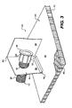
- FIGURE 1 is an axonometric view showing the interior of a transport container secured to a flatbed of a truck or truck trailer, with cargo stabilized within the container in accordance with the subject invention;
- FIGURE 2 is a top view showing the interior of a transport container such as a truck trailer or the like where a plurality of void filler stabilizers, in accordance with the invention, are shown occupying different dimensional spaces;
- FIGURE 3 is a pictorial view of the present invention showing a first tubular, male, element of one preferred embodiment of the subject invention;
- FIGURE 4 is a pictorial view of the present invention showing a second tubular, female, element of the embodiment of the invention depicted in Figure 3;
- FIGURE 5 is a cross sectional view of the present invention showing the first and second tubular elements and their respective base elements prior to mutual engagement;
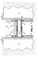
- FIGURE 6 is a cross sectional view of the present invention showing each of two tubular elements and their respective bases after engagement, in situ, between two opposing load faces;
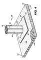
- FIGURE 7 is an axonometric view of an alternative preferred embodiment of the subject void filler invention where enlarged end flanges are designed to abut directly against cargo to be stabilized or a container wall surface;
- FIGURE 8 is a cross sectional view taken along section line 8 - 8 in Figure 7;
- FIGURE 9 is a cut-away axonometric view of a female component of the void filler depicted in Figure 7;
- FIGURE 10 is side cross-sectional view of a void filler as disclosed in Figures 7 - 9 including a torque tensioning member integral with a female component of the void filler device; and
- FIGURE 11 is a cross-sectional view of the tubular torque element of the void filler disclosed in Figure 10.
- Turning now to the drawing wherein like numerals indicate like parts, Figure 1 shows an axonometric view of an operating environment of the invention. In this, a transport or
cargo container 20 is shown mounted upon atrailer 22 which is towed by atractor 24 for land transport. Containers such as these are also operable to be mounted on railway flat cars either directly or attached totrailers 22. This form of container is merely illustrative and the subject invention can be used to advantage in ship cargo holds, intermodal containers, tractor trailers, overland truck bodies, rail road boxcars, and the like. - A partially cut away portion of Figure 1 depicts various size and shapes of cargo, which are stabilized against each other and against the
internal walls 26 of thecontainer 20 byload stabilizers 30 in accordance with the subject invention. - Figure 2 further illustrates details of the illustrative operating environment shown in Figure 1. In this view, transport or
cargo container 20 is again shown towed by atractor 24 for land transport. A partially cut away portion of Figure 2 depicts cargo including various sizes of large boxes orsuper sacks 32, smaller boxes onpallets 34 anddrums 36, all being stabilized against each other and/or against theinternal walls 26 of thecontainer 20 by a plurality of void fillers andload stabilizers 30 in accordance with the subject invention. - Figure 3 is an axonometric view of a
male portion 40 of one embodiment of the presentvoid filler invention 30 showing a maletubular element 42 and a composite base. More particularly, the first or maletubular member 42 of a void filler column mechanism is shown having anabutment flange 46 at one end andexternal threads 48 at the other end. Thetubular member 42 has an enlargedperipheral collar 50 adjacent to theflange 46 with a roughened exterior peripheral surface formed by knurling or the like or the addition of one or more longitudinally extending raised spines orribs 52 extending along thecollar 50 to facilitate grip for rotation of thetubular element 42 with respect to the base as will be discussed below. Creation of one or more ribs orspines 52 also serves as a stiffening structural element to prevent bending of thecolumn 42 and strengthening of the junction of the column and theflange 46 against flexure or breakage. In those circumstances where hand tighteriing is not sufficient for the cargo to be secured a conventional belt wrench may be wrapped around and engage the roughened surface or raisedridges 52 ofcollar 50. Moreover, the belt of the belt wrench may be fabricated with roughened interior surfaces to correspond to surface 50 to facilitate gripping without slippage. Alternatively,collar 50 may have an area that is molded to fit a standard hexagonal wrench for tensioning as shown in Figure 7. - The first
tubular element 42 is connected to a loaddistribution base panel 44 through aset 54 offoldable engagement panels panel 56 of the set offoldable panels 54 has anaperture 60 that serves to locate and support the firsttubular element 42. Thesecond engagement panel 58 serves as a load distributing abutment element for theflange 46 to distribute axial loading of thetubular member 42 onto thebase panel 44. Theengagement panels ridge 62 and one of the panels is in turn pivotally hinged as at 64 to anouter surface 66 of theload distribution panel 44. - The load
distribution base panel 44 is composed ofouter surface 66 composed of a heavy grade paper or plastic sheeting and is glued to an array of verticalhoney comb columns 68. An outer surface of thehoney comb columns 68 is covered by another layer of paper orplastic sheeting 70 or the like to provide a light weight but structurally rigid andstrong base panel 44 to distribute loading across a cargo surface and an axiallyadjustable column 42 of the subject void filler system. In an alternative embodiment,load distribution panel 44 may be composed of a double wall corrugated cardboard. - Turning now to Figure 4 there will be seen a
void filler element 80 which is a female counterpart to the malevoid filler element 40 as discussed in connection with Figure 3 above. More specifically, Figure 4 discloses a secondtubular member 82 and acomposite base 84. The secondtubular member 82 has acylindrical body component 86 with aflange 88 at one end (note Figure 5) andinternal thread elements 90, which are designed and dimensioned to cooperate withexternal threads 48 of the firsttubular member 42. - The
cylindrical body component 86 can have a smooth outer surface or more preferably an outer surface that is roughened as by a furling procedure to facilitate gripping. In addition, in instances of rugged application the outer surface is fashioned with one or more longitudinally extendingridges 92 that enhance the structural rigidity of thesecond columnar member 82 against bending. Moreover theridges 92 are integrally joined with theflange 88 to help to support and secure the flange against bending under axial loading of thetubular member 82. - In operation, (note again Figure 3) the first
tubular member 42 is fitted into the set offoldable panels flange 46 is located between the twopanels set 54 and rotation of thetubular member 42 relative to thebase panel 44 is permitted. Once thetubular member 42 is placed into theset 54 offoldable panel wings foldable panels 54 is collapsed ontobase panel 44 in a structural manner similar to that shown in Figure 4. In a similar manner the secondtubular member 82 is secured between aset 94 ofpanels composite base 84. - The
flange 88, in one embodiment, is secured within theset 94 offoldable engagement panels panels panel 98 abuts against aload distribution panel 100 having an outer surface 102 composed of paper or plastic, interiorhoney comb columns 104 and anouter skin 106. The load distribution panel comprises a honey comb composite that is both strong and light weight. In an alternative embodiment,load distribution panel 44 may be composed of a double wall corrugated cardboard. - The
tubular members columns tubular members tubular members - The
external threads 48 of the maletubular element 42 shown in Figure 3 and theinternal threads 90 of the correspondingfemale tubular member 82 shown in Figure 4 are preferably rugged and extend along thetubular members tubular members tubular members - In Figure 3 and Figure 4, the sets of
foldable wings flanges tubular member 42 and secondtubular member 82 on their respective compositeload distribution panels tubular member 42 and secondtubular member 82 to aload distribution base tubular members base tubular members bases - Figure 5 is a cross-sectional view of the various elements of the present invention showing a
load stabilizer 30 comprising a malevoid filler element 40 and a femalevoid filler element 80. Afirst tubular member 42 and a secondtubular member 82 are shown, each having aflange foldable wings base tubular member 42 hasexternal threads 48, which are operable to engageinternal threads 90 of the secondtubular member 82. Thetubular member 42 has a plurality of longitudinally extending raised spines orribs 52 to facilitate grip for rotation of thetubular element 42 and for strength as discussed above. The secondtubular member 82 similarly has a plurality of longitudinally extendingridges 92 which facilitate grip and strength of thecomponent 82. In the depicted embodiment, a set ofwings 162 is further shown to maintain the vertical position of theload stabilizer 30 with respect to cargo. - Figure 6 is a view similar to figure 5; however, in this view the void filler is shown operably positioned between opposing surfaces of
cargo components 32. The male andfemale components - The first
tubular member 42 and secondtubular member 82 are mutually extensible with respect to each other upon rotation of one tubular member with respect to the other. The extension mechanism shown in Figures 3-6comprise threads 48 on the firsttubular member 42, which engage with compatibleinternal threads 90 on the secondtubular member 82 such that the tubular members are selectively extensible with respect to each other upon the rotation of one with respect to the other. Although threaded elements are preferred other extension mechanisms are contemplated such as a plurality of radial holes within both columns and a pin extending through aligned holes. Alternatively, a ratched mechanism may be used between the columnar members; however, threads are preferred. In addition, a lockingwasher 160, as shown in Figure 7, can be used to prevent the tubular members from becoming loose once extended. Alternatively, it is envisioned that other means may be employed for securing the axial position of the tubular members between a cargo surface and an opposing cargo surface or wall of a container to maintain the cylinder in an extended and secure position. As an example, tape or other retaining means such as an axial pin extending between the two columns may be employed to prevent counter rotation of the void filler after the axial position of the columns is extended and snuggly set between cargo surfaces or between cargo and a side wall of a container. This securing or locking element may take various other forms and the intent of this disclosure is to include all of the various extension mechanisms and locking mechanisms that may be used to lock the columns together. - One of skill in the art will see that other methods for extending and locking the extension of the first and second
tubular members - In Figure 6 each of the first
tubular member 42 and secondtubular member 82 has aflange foldable wings load distribution panel load stabilizer 30 is extensible to fill the space between loads ofcargo 32 by rotating one of thetubular members cargo 32 with respect to the other 32. In the depicted embodiment, a set ofwings 162 is further shown to maintain the vertical position of theload stabilizer 30 with respect to thecargo 32. - Although Figure 6 illustrates the use of a load stabilizer between two loads of
cargo 32. In an alternative use of the invention, theload stabilizer 30 can be placed betweencargo 32 and an internal wall of a transport container. At least one base element of the load stabilizer, however, is in contact with cargo to be stabilized. - Figure 7 is an axonometric view of an alternative preferred embodiment of the subject invention where enlarged end flanges act as bases, which are designed to abut directly with cargo to be stabilized. Figure 7 illustrates the various elements of the present invention showing a
load stabilizer 30 comprising a malevoid filler element 110 and a femalevoid filler element 112. The malevoid filler element 110 comprises a firsttubular member 114 and a base 116 in the form of anenlarged flange 118. The firsttubular member 114 hasexternal threads 120 and a plurality of longitudinally extending raised spines orribs 122 to facilitate grip for rotation of thetubular element 110 relative to the femaletubular element 112. - The second
tubular member 112 comprises acylindrical body 124 having internal threads 126 (note Figure 10), which are operable to engage theexternal threads 120 of the firsttubular member 110. The secondtubular member 112 similarly has a plurality of longitudinally extending raisedridges 128 to facilitate rotation and provide strength for the column and an extra attachment for anenlarged flange 130 comprising abase 132 of thefemale component 112. The embodiment depicted further includes anarea 164 that is molded to fit a standard hexagonal wrench for tensioning. - In the embodiment depicted in Figure 7, the load void filler and stabilizer comprises a set of
void filler elements tubular elements base flanges void filler element 30 further has anadhesive element 140 applied to an outer surface of theflange 118. This adhesive carries a release paper, not shown, which is removed on site and serves to locate and prevent rotation of one end of the void filler as it is being applied as will be discussed below. - The
enlarged flanges adhesive element 140 serves to adhere theflange 118 to a load of cargo to be stabilized or an internal wall of a transport container to prevent rotation of the malevoid filler element 110 during application.Void filler element 112 can then be rotated with respect to malevoid filler element 110 to allow for the extension of theload stabilizer 30 to fill the space between a load of cargo to be stabilized and another load of cargo or an internal wall of a transport container. - Figure 8 is a cross-sectional view of the present embodiment of the invention as shown in Figure 7. This cross-sectional view illustrates the female
tubular member 112 in cross-section with strengtheningribs 128 shown positioned about the periphery of thetubular element 124. Theribs 128 not only provide bending rigidity to the tubular column and an element of grip for rotation but also provide abutting support for theload bearing flange 130 extending radially away from thecolumn 124. - Figure 9 is a partial axonometric view of a
female component 112 of the void filler depicted in Figure 7. Figure 9 shows the interior surfaces of a femalevoid filler element 112 having acylindrical body component 124 and aflange 130 comprising abase 132. The secondtubular member 112 hasinternal threads 126. As described above, theinternal threads 126 serve to engage with theexternal threads 120 of the corresponding firstmale tubular member 110 as shown in Figure 7. The secondtubular member 112 has a plurality of longitudinally extending raisedridges 128 to facilitate rotation. - Figure 10 is a side cross-sectional view of a void filler as disclosed in Figures 7 - 9 positioned between two loads of
cargo 32. Figure 10 shows the engagement of a malevoid filler element 110 and a femalevoid filler element 112 into aload stabilizer 30. The malevoid filler element 110 has a firsttubular member 114 and a base 116 in the form of aflange 118. The firsttubular member 114 has a set ofexternal threads 120 and a plurality of longitudinal extending raised spines orribs 122. The second or femaletubular member 112 has a set ofinternal threads 126 operable to engage theexternal threads 120 and a plurality of longitudinally extending raised strengtheningridges 128. In the depicted embodiment, the secondtubular member 112 further has atorque tensioning member 150 connected to the exterior surface of thecylinder 124. - In the depicted embodiment, the
flanges cargo 32 to be stabilized. Anadhesive element 140 serves to adhere theflange 118 to the load ofcargo 32 to prevent rotation of thevoid filler element 110 with respect to thecargo 32.Void filler element 112 can then be rotated with respect to voidfiller element 40 to allow for the extension of theload stabilizer 30 to fill the space between two loads of cargo to be stabilized 32. Atorque tensioning member 150 is optionally used to facilitate rotation of thevoid filer element 112 with respect to voidfiller element 110. - Figure 11 is a front cross-sectional view of a
tubular element 124 of thevoid filler 112 disclosed in Figure 10. Figure 11 illustrates a second femaletubular element 112 with acylindrical body component 124, aflange 130, and an optionaltorque tensioning member 150 as described above. In this, the tensioningmember 150 includes a radially extending handle 152 which is either integrally joined with theelement 112 or one element of a belt type wrench. In the latter instance, at least onelongitudinal groove 154 is fashioned within the base of the wrench and serves to operably engage with one of thelongitudinal ridges 128 of thefemale member 112. The wrench is operably held in place by abelt 156 which extends about theelement 112 and selectively attaches to the wrench as at 158 by a snap or other attachment element. Accordingly, in this embodiment the wrench may be used repeatedly to tighten a plurality of void spacer units and then removed upon completion of a securement operation. - In operation, cargo to be secured is loaded into a ship's hold, truck trailer, boxcar, container, or the like and extensible load stabilizers are delivered to a container site.
Load stabilizers 30 are provided having a firsttubular member tubular member external threads internal threads peripheral collar 50 and 64 with longitudinally extending raised spines orribs hexagonal wrench 164 or atorque tensioning member 150 as described above. - The
load stabilizers 30 are positioned between a first surface and an opposing second surface within the transport container. One base is positioned relative to a surface of cargo to be stabilized and the other base is positioned relative to an opposing surface within the transport container such as another surface of cargo or an internal wall of the transport container. The first 40 and 110 and second 80 and 112 tubular members are extended with respect to each other between the opposing surfaces and stabilize the cargo against the opposing surface within the transport container. - The subject invention provides a unique method and apparatus for stabilizing and enhancing resistance to shifting of cargo within transport containers which is convenient and easy to install preferably by hand and in any event merely with light-weight tools such as a belt wrench.
- The invention also provides an entirely self-contained cargo stabilization system with extensible tubes between opposing bases that operably distributed loads.
- This invention further provides a method and apparatus for stabilizing cargo having enhanced compression strength so that a load is securely restrained during transport but upon arrival at the destination, it may be quickly removed and disposed of or stored for re-use.
- Another significant advantage of the subject invention is ability to customize the length of the cargo stabilizer to varying spaces between cargo in a transport load.
- A further advantage of the subject invention is the ability to withstand the substantial force generated by restraining the transport of heavy cargo by distributing the load across a first column abutment panel and then a larger load abutment base panel.
- The strengthening ribs advantageously provide not only structural rigidity for the columns but strengthen the flanges against bending and breakage. Moreover, the strengthening ribs provide a means for securely gripping the cylinder to facilitate securement.
- The subject void fillers are inexpensive to manufacture, rugged in operation and easily adoptable to varying size and shaped loads.
- In describing the invention, reference has been made to preferred embodiments. Those skilled in the art, however, and familiar with the disclosure of the subject invention, may recognize additions, deletions, substitutions, modifications and/or other changes which will fall within the purview of the invention as defined in the following claims.
Claims (24)
- An apparatus for stabilizing cargo within a transport container, said apparatus comprising:a first tubular member having
a generally cylindrical body, and
a first base at one end, said first base of said first tubular member being operable to react against a surface of cargo to be stabilized;a second tubular member having
a generally cylindrical body, and
a second base at one end, said second base being operable to react against an opposing surface within the transport container;
the other end of said second tubular member being operable to engage and selectively translate with respect to the other end of said first tubular member; andan extension mechanism, said extension mechanism being operable to allow selective translation between said first and said second tubular members;wherein said apparatus for stabilizing, being operable to be placed between a surface of cargo to be stabilized and at least one of an opposing surface of other cargo and an internal wall of a transport container, stabilizes the cargo within the container by extending and filling the space between opposing surfaces within the transport container. - An apparatus for stabilizing cargo within a transport container as defined in claim 1, wherein:each of said first tubular member and said second tubular member has at least one longitudinally extending rib positioned upon an exterior surface of said generally cylindrical body.
- An apparatus for stabilizing cargo within a transport container as defined in claim 1, and further comprising:a plurality of longitudinal ribs extending at least partially along the exterior surface of said generally cylindrical bodies and each of said ribs abutting against and joining with respective one of said bases.
- An apparatus for stabilizing cargo within a transport container as defined in claim 4, and further comprising:means for securing the axial position of said first and second tubular members between a cargo surface and at least one of an opposing cargo surface and a wall surface of a container.
- An apparatus for stabilizing cargo within a transport container as defined in claim 1 wherein:said extension mechanism comprises:external threads on the exterior surface of the other end of one of said first and second tubular members;internal threads on the interior surface of the other end of the other of said first and second tubular members; said internal threads being operable to engage said external threads for axial translation of said first and second tubular members with respect to each other.
- An apparatus for stabilizing cargo within a transport container, said apparatus comprising:a first tubular member having
a generally cylindrical body, and
a first base at one end, said first base comprising:a first load distribution panel operable for engagement with said base of said first tubular member for distributing reaction force between said first tubular member and cargo surface to be stabilized;a second tubular member havingsaid second tubular member being operable to engage and selectively translate with respect to said first tubular member;
a generally cylindrical body, and
a second base at one end, said second base comprisinga second load distribution panel operable for engagement with said base of said second tubular member for distributing reaction force between said second tubular member and an opposing surface within the transport container;
wherein said apparatus, being operable to be placed between a surface of cargo to be stabilized and an opposing surface within the transport container for stabilizing cargo within the container by extending between said opposing surfaces within the transport container. - An apparatus for stabilizing cargo within a transport container as defined in claim 6, and further comprising:a first L-shaped member coupled to said first base; anda second-L shaped member coupled to said second base,said first and second L-shaped members being operable to maintain the vertical position of the apparatus with respect to the cargo to be stabilized.
- An apparatus for stabilizing cargo within a transport container as defined in claim 6, and further comprising:first and second engagement panels for supporting said first and second tubular members with said first and said second load distribution panels, respectively.
- An apparatus for stabilizing cargo within a transport container as defined in claim 7, wherein:said first and said second engagement panels each include an aperture operable to generally fit and be slightly larger than the diameter of the respective one of said first and said second tubular members.
- An apparatus for stabilizing cargo within a transport container as defined in claim 8, wherein:said first load distribution panel is larger in surface area than said first engagement panel and is operable for distributing axial loading between said first engagement panel and a surface of cargo to be stabilized; andsaid second load distribution panel is larger in surface area than said second engagement panel and is operable for distributing axial loading between said second engagement panel and an opposing surface within the transport container.
- An apparatus for stabilizing cargo within a transport container as defined in claim 10, wherein:said first and second load distribution panels have greater lateral dimensions and thickness than said first and second engagement panels.
- An apparatus for stabilizing cargo within a transport container, said apparatus comprising:a first tubular member having
a generally cylindrical body,
a first base at one end, and
external threads at the other end; anda second tubular member havingone of said first and said second bases being operable to react against a surface of cargo to be stabilized; and
a generally cylindrical body,
a second base at one end,
and internal threads at the other end, said internal threads being operable to receive said external threads of said first tubular member for axial translation of said second tubular member with respect to said first tubular member;
the other of said first and said second bases being operable to react against an opposing surface within the transport container, wherein said apparatus stabilizes the cargo by extending and filling the space between opposing surfaces within the transport container. - An apparatus for stabilizing cargo within a transport container as defined in claim 12, and further comprising:an adhesive element coupled to one of said first or said second bases, said adhesive element being operable to locate and prevent rotation of said one of said first or said second bases carrying said adhesive element.
- An apparatus for stabilizing cargo within a transport container as defined in claim 12, wherein:at least one of said first or second tubular members further comprises an exterior surface operable for receiving rotational force applied to the exterior of said at least one of said tubular members.
- An apparatus for stabilizing cargo within a transport container as defined in claim 14, wherein:said exterior surface comprises an area molded to fit a standard hexagonal wrench.
- An apparatus for stabilizing cargo within a transport container as defined in claim 14, wherein:said exterior surface comprises a plurality of longitudinally extending raised spines or ribs.
- An apparatus for stabilizing cargo within a transport container as defined in claim 14, wherein:said exterior surface is a torque tensioning member.
- An apparatus for stabilizing cargo within a transport container as defined in claim 12 wherein:at least one of said first and said second tubular members is rotatably coupled to said base.
- An apparatus for use in stabilizing cargo within a transport container as defined in claim 18 wherein:at least one of said tubular members further comprises a flange on the end proximal to said base that allows distribution of forces to said base, said flange providing a mechanism for rotating said at least one of said tubular members relative to said base.
- An apparatus for use in stabilizing cargo within a transport container as defined in claim 19, and further comprising:a set of foldable wings, said set of foldable wings retaining said at least one of said tubular members and said flange onto said base.
- A method of stabilizing cargo within a transport container comprising the steps of:providing an extensible load stabilizer having a first tubular member having a first base at one end and a second tubular member having a second base at one end;positioning said load stabilizer between a first surface and an opposing second surface within the transport container, said first base being applied relative to said first surface and said second base being applied relative to said opposing second surface; andextending said first tubular member with respect to said second tubular member, said load stabilizer extending generally between said first surface and said opposing second surface and stabilizing said first surface against said opposing second surface;wherein at least one of said first surface and said opposing second surface is a surface of cargo to be stabilized and the other of said first surface and said opposing second surface is at least one of a surface of cargo and an internal wall of a transport container.
- A method of stabilizing cargo within a transport container as defined in claim 21, wherein:said step of providing further comprises providing a first tubular member having internal threads and a second tubular member having external threads being operable to engage said internal threads; andsaid step of extending comprises rotating at least one of said first and said second tubular members with respect to the other of said first and said second tubular members to allow the relative axial motion between said first and said second tubular members.
- A method of stabilizing cargo within a transport container claimed in claim 22, and further comprising:providing an exterior surface operable for receiving rotational force applied to the exterior of said at least one of said tubular members.
- A method of stabilizing cargo within a transport container claimed in claim 21 wherein:said step of providing further comprises rotatably coupling at least one of said first tubular member and said second tubular member to said first base and said second base, respectively.
Applications Claiming Priority (1)
| Application Number | Priority Date | Filing Date | Title |
|---|---|---|---|
| US11/127,193 US7322781B2 (en) | 2005-05-12 | 2005-05-12 | Adjustable load stabilizer method and apparatus |
Publications (2)
| Publication Number | Publication Date |
|---|---|
| EP1721781A2 true EP1721781A2 (en) | 2006-11-15 |
| EP1721781A3 EP1721781A3 (en) | 2007-12-05 |
Family
ID=36794877
Family Applications (1)
| Application Number | Title | Priority Date | Filing Date |
|---|---|---|---|
| EP06009457A Withdrawn EP1721781A3 (en) | 2005-05-12 | 2006-05-08 | Adjustable load stabilizer method and apparatus |
Country Status (3)
| Country | Link |
|---|---|
| US (1) | US7322781B2 (en) |
| EP (1) | EP1721781A3 (en) |
| WO (1) | WO2006124403A2 (en) |
Cited By (2)
| Publication number | Priority date | Publication date | Assignee | Title |
|---|---|---|---|---|
| DE102007043743A1 (en) * | 2007-09-18 | 2009-03-19 | TANOS GmbH Verpacken Ordnen Präsentieren | Holding device for vehicle interiors, particularly component of storage system for articles that are carried in vehicle, has holding bar, and supporting limbs are arranged at vehicle walls |
| US8328481B2 (en) | 2007-09-18 | 2012-12-11 | Tanos Gmbh Verpacken Ordnen Prasentieren | Retaining device for vehicle interiors |
Families Citing this family (18)
| Publication number | Priority date | Publication date | Assignee | Title |
|---|---|---|---|---|
| US7708508B2 (en) * | 2006-07-23 | 2010-05-04 | Matthew Bullock | Adjustable load stabilizer method and apparatus |
| US20080181742A1 (en) * | 2007-01-31 | 2008-07-31 | Steven Dry | Woven bracing for intermodal transport |
| US7726920B2 (en) * | 2007-01-31 | 2010-06-01 | Matthew Bullock | Modular adjustable load stabilizer method and apparatus |
| CA2639622C (en) | 2007-09-20 | 2014-05-20 | Mathieu Boivin | Collapsible container |
| US20100155291A1 (en) * | 2008-12-18 | 2010-06-24 | Bruce Dunn | Packaging |
| US20100316461A1 (en) * | 2009-06-16 | 2010-12-16 | Huchler Thomas M | Inflatable cargo cushion |
| US8419329B1 (en) | 2011-10-28 | 2013-04-16 | Matthew Bullock | Cargo restraint system with enhanced polyester reinforcement filament strand denier content |
| US8403609B1 (en) | 2011-10-28 | 2013-03-26 | Matthew Bullock | Cargo restraint system with enhanced reinforcement filament break strength content |
| US8408852B1 (en) | 2011-10-28 | 2013-04-02 | Matthew Bullock | Cargo restraint system with enhanced reinforcement content |
| US8403607B1 (en) | 2011-10-28 | 2013-03-26 | Matthew Bullock | Cargo restraint system with enhanced reinforcement end filament content |
| US8403608B1 (en) | 2011-10-28 | 2013-03-26 | Matthew Bullock | Cargo restraint system with enhanced reinforcement filament content |
| US9504617B2 (en) | 2014-07-15 | 2016-11-29 | 4One, Llc | Mobility securement system |
| US9585800B2 (en) | 2014-07-15 | 2017-03-07 | 4One, Llc | Mobility securement system |
| US9333899B1 (en) | 2014-12-23 | 2016-05-10 | Matthew Bullock | Securing cargo for rail transport using polymer foam material |
| US10132911B1 (en) | 2017-05-19 | 2018-11-20 | Matthew Bullock | Cargo restraint with RF beacon |
| CN110092107A (en) * | 2019-06-03 | 2019-08-06 | 北京鸿通供应链管理有限公司 | The lateral supporting device of cargo in container, cargo reinforcement means in container |
| US11618370B2 (en) | 2020-09-30 | 2023-04-04 | Matthew Bullock | Cargo restraint panel with compressible side cover |
| US20220194677A1 (en) * | 2020-12-22 | 2022-06-23 | Douglas Gerhart | Support beam for a transport container |
Citations (2)
| Publication number | Priority date | Publication date | Assignee | Title |
|---|---|---|---|---|
| US6089802A (en) | 1998-02-23 | 2000-07-18 | Bullock; Matthew | Cargo restraint system for a transport container |
| US6607337B1 (en) | 2000-05-05 | 2003-08-19 | Matthew Bullock | Cargo restraint system |
Family Cites Families (24)
| Publication number | Priority date | Publication date | Assignee | Title |
|---|---|---|---|---|
| US2199851A (en) * | 1938-07-16 | 1940-05-07 | Culver John Freeman | Shower curtain rod |
| US2974931A (en) * | 1957-05-28 | 1961-03-14 | Roy C Reel | Load holder |
| CA880060A (en) | 1969-02-06 | 1971-09-07 | Grant Andrew | Wedging device for pallet loads |
| US4553888A (en) | 1983-06-23 | 1985-11-19 | Aeroquip Corporation | Captive dunnage fitting |
| US4815905A (en) * | 1987-04-22 | 1989-03-28 | Garcia Jr Jose | Load stabilizer for cargo carrying vehicle |
| US5037256A (en) | 1989-12-04 | 1991-08-06 | Schroeder Robert C | Dunnage bar lock |
| US5132156A (en) | 1990-03-07 | 1992-07-21 | Down River International, Inc. | Void filler |
| US5062751A (en) | 1991-03-13 | 1991-11-05 | Shippers Paper Products Company | Economy void filler |
| US5139842A (en) | 1991-06-04 | 1992-08-18 | Sewell James D | Dunnage device |
| US5484643A (en) | 1993-09-09 | 1996-01-16 | Wise; Frederick M. | Space filling unit and method of use therefor |
| US5855459A (en) | 1995-09-19 | 1999-01-05 | Packaging Unlimited Of Nk, Inc. | Void filler and load retainer |
| US5846038A (en) | 1996-08-21 | 1998-12-08 | Corrugated Container Corp. | Void filler with multiple intersecting cells |
| US5947666A (en) | 1998-10-19 | 1999-09-07 | Huang; Han-Ching | Cargo positioning device with quick retraction and reliable retaining function |
| DE29901812U1 (en) * | 1999-02-03 | 1999-04-15 | Meha | Strut-like transport securing device |
| DE19929310A1 (en) * | 1999-06-25 | 2000-12-28 | Combined Container Service Gmb | Securing device for goods on palette in container comprises support fitted to inside of container wall, second support fitted against side of palette and spacer holding supports apart |
| DE20004935U1 (en) * | 2000-01-21 | 2000-08-24 | Cramer Degenhard | Automatically activating stand protection II in drawn or self-driving animal transports |
| TW553332U (en) * | 2000-03-28 | 2003-09-11 | Chiung-Mei Huang | Improved alignment apparatus for retractable supporting shaft |
| US6419434B1 (en) | 2000-05-01 | 2002-07-16 | Harper Trucks, Inc. | Adjustable length cargo brace |
| US6322303B1 (en) | 2000-05-12 | 2001-11-27 | David M. John | Dunnage bag and method of making same |
| DE10056529A1 (en) * | 2000-11-15 | 2002-05-23 | Huang Han Ching | Freight positioning device comprises outer and inner tube telescopically assembled, with at least one from first end of outer tube and first end of inner tube having internal thread for threaded engagement of screw spindle |
| US6568636B2 (en) | 2001-02-07 | 2003-05-27 | Capewell Components Company Limited Partnership | Buffer stop assembly |
| US6527488B2 (en) | 2001-03-21 | 2003-03-04 | Helmut Elze | Dunnage bag having a mesh ply |
| US6533513B2 (en) | 2001-05-01 | 2003-03-18 | Logistick, Inc. | Cargo restraint device |
| US6736371B1 (en) * | 2002-03-27 | 2004-05-18 | Ancra International, Llc. | Extendible jack bar |
-
2005
- 2005-05-12 US US11/127,193 patent/US7322781B2/en active Active
-
2006
- 2006-05-08 EP EP06009457A patent/EP1721781A3/en not_active Withdrawn
- 2006-05-09 WO PCT/US2006/017887 patent/WO2006124403A2/en active Application Filing
Patent Citations (3)
| Publication number | Priority date | Publication date | Assignee | Title |
|---|---|---|---|---|
| US6089802A (en) | 1998-02-23 | 2000-07-18 | Bullock; Matthew | Cargo restraint system for a transport container |
| US6227779B1 (en) | 1998-02-23 | 2001-05-08 | Matthew Bullock | Cargo restraint method for a transport container |
| US6607337B1 (en) | 2000-05-05 | 2003-08-19 | Matthew Bullock | Cargo restraint system |
Cited By (2)
| Publication number | Priority date | Publication date | Assignee | Title |
|---|---|---|---|---|
| DE102007043743A1 (en) * | 2007-09-18 | 2009-03-19 | TANOS GmbH Verpacken Ordnen Präsentieren | Holding device for vehicle interiors, particularly component of storage system for articles that are carried in vehicle, has holding bar, and supporting limbs are arranged at vehicle walls |
| US8328481B2 (en) | 2007-09-18 | 2012-12-11 | Tanos Gmbh Verpacken Ordnen Prasentieren | Retaining device for vehicle interiors |
Also Published As
| Publication number | Publication date |
|---|---|
| US7322781B2 (en) | 2008-01-29 |
| US20060257226A1 (en) | 2006-11-16 |
| EP1721781A3 (en) | 2007-12-05 |
| WO2006124403A3 (en) | 2007-07-05 |
| WO2006124403A2 (en) | 2006-11-23 |
Similar Documents
| Publication | Publication Date | Title |
|---|---|---|
| US7322781B2 (en) | Adjustable load stabilizer method and apparatus | |
| US8398344B2 (en) | Adjustable load stabilizer method and apparatus | |
| EP2261031B1 (en) | Cargo restraint method and system with enhanced shear strength | |
| US7329074B2 (en) | Cross-weave cargo restraint system and method | |
| US6089802A (en) | Cargo restraint system for a transport container | |
| EP2263870B1 (en) | Cargo restraint system and method with enhanced peel strength | |
| US7260870B2 (en) | Associated strap of a composite restraint system for securing freight | |
| US7604443B2 (en) | Adjustable load stabilizer method and apparatus | |
| US7066698B2 (en) | Cross-weave cargo restraint system | |
| US6607337B1 (en) | Cargo restraint system | |
| US6981827B2 (en) | Cargo restraint torque apparatus | |
| US6896457B2 (en) | Clamping system and method for securing freight | |
| WO2013062901A1 (en) | Cargo restraint system with enhanced polyester reinforcement filament strand denier content | |
| US11752918B2 (en) | Bendable cargo securement device and method | |
| EP2771221A1 (en) | Cargo restraint system with enhanced reinforcement end filament content | |
| US20050123369A1 (en) | Monolithic cargo restraint system and method | |
| US7726920B2 (en) | Modular adjustable load stabilizer method and apparatus | |
| US4371298A (en) | Vehicle supporting ramps for cargo containers | |
| US5418038A (en) | Space filling device | |
| US20230192430A1 (en) | Load strap retracting device |
Legal Events
| Date | Code | Title | Description |
|---|---|---|---|
| PUAI | Public reference made under article 153(3) epc to a published international application that has entered the european phase |
Free format text: ORIGINAL CODE: 0009012 |
|
| AK | Designated contracting states |
Kind code of ref document: A2 Designated state(s): AT BE BG CH CY CZ DE DK EE ES FI FR GB GR HU IE IS IT LI LT LU LV MC NL PL PT RO SE SI SK TR |
|
| AX | Request for extension of the european patent |
Extension state: AL BA HR MK YU |
|
| PUAL | Search report despatched |
Free format text: ORIGINAL CODE: 0009013 |
|
| AK | Designated contracting states |
Kind code of ref document: A3 Designated state(s): AT BE BG CH CY CZ DE DK EE ES FI FR GB GR HU IE IS IT LI LT LU LV MC NL PL PT RO SE SI SK TR |
|
| AX | Request for extension of the european patent |
Extension state: AL BA HR MK YU |
|
| 17P | Request for examination filed |
Effective date: 20080430 |
|
| AKX | Designation fees paid |
Designated state(s): AT BE BG CH CY CZ DE DK EE ES FI FR GB GR HU IE IS IT LI LT LU LV MC NL PL PT RO SE SI SK TR |
|
| GRAP | Despatch of communication of intention to grant a patent |
Free format text: ORIGINAL CODE: EPIDOSNIGR1 |
|
| STAA | Information on the status of an ep patent application or granted ep patent |
Free format text: STATUS: THE APPLICATION HAS BEEN WITHDRAWN |
|
| 18W | Application withdrawn |
Effective date: 20090424 |