EP1721775A2 - Control apparatus for an eletric locomotive - Google Patents
Control apparatus for an eletric locomotive Download PDFInfo
- Publication number
- EP1721775A2 EP1721775A2 EP06113492A EP06113492A EP1721775A2 EP 1721775 A2 EP1721775 A2 EP 1721775A2 EP 06113492 A EP06113492 A EP 06113492A EP 06113492 A EP06113492 A EP 06113492A EP 1721775 A2 EP1721775 A2 EP 1721775A2
- Authority
- EP
- European Patent Office
- Prior art keywords
- converter
- inverter
- electric motor
- motor
- regeneration
- Prior art date
- Legal status (The legal status is an assumption and is not a legal conclusion. Google has not performed a legal analysis and makes no representation as to the accuracy of the status listed.)
- Withdrawn
Links
- 230000003137 locomotive effect Effects 0.000 title 1
- 238000010521 absorption reaction Methods 0.000 claims abstract description 55
- 238000001514 detection method Methods 0.000 claims abstract description 45
- 230000005540 biological transmission Effects 0.000 claims abstract description 6
- 230000008929 regeneration Effects 0.000 claims description 52
- 238000011069 regeneration method Methods 0.000 claims description 52
- 239000003990 capacitor Substances 0.000 claims description 35
- 238000010586 diagram Methods 0.000 description 7
- 238000000034 method Methods 0.000 description 4
- 230000000694 effects Effects 0.000 description 2
- 230000005611 electricity Effects 0.000 description 2
- 230000008602 contraction Effects 0.000 description 1
- 230000001360 synchronised effect Effects 0.000 description 1
Images


Classifications
-
- B—PERFORMING OPERATIONS; TRANSPORTING
- B60—VEHICLES IN GENERAL
- B60L—PROPULSION OF ELECTRICALLY-PROPELLED VEHICLES; SUPPLYING ELECTRIC POWER FOR AUXILIARY EQUIPMENT OF ELECTRICALLY-PROPELLED VEHICLES; ELECTRODYNAMIC BRAKE SYSTEMS FOR VEHICLES IN GENERAL; MAGNETIC SUSPENSION OR LEVITATION FOR VEHICLES; MONITORING OPERATING VARIABLES OF ELECTRICALLY-PROPELLED VEHICLES; ELECTRIC SAFETY DEVICES FOR ELECTRICALLY-PROPELLED VEHICLES
- B60L9/00—Electric propulsion with power supply external to the vehicle
- B60L9/16—Electric propulsion with power supply external to the vehicle using AC induction motors
-
- B—PERFORMING OPERATIONS; TRANSPORTING
- B60—VEHICLES IN GENERAL
- B60L—PROPULSION OF ELECTRICALLY-PROPELLED VEHICLES; SUPPLYING ELECTRIC POWER FOR AUXILIARY EQUIPMENT OF ELECTRICALLY-PROPELLED VEHICLES; ELECTRODYNAMIC BRAKE SYSTEMS FOR VEHICLES IN GENERAL; MAGNETIC SUSPENSION OR LEVITATION FOR VEHICLES; MONITORING OPERATING VARIABLES OF ELECTRICALLY-PROPELLED VEHICLES; ELECTRIC SAFETY DEVICES FOR ELECTRICALLY-PROPELLED VEHICLES
- B60L58/00—Methods or circuit arrangements for monitoring or controlling batteries or fuel cells, specially adapted for electric vehicles
- B60L58/10—Methods or circuit arrangements for monitoring or controlling batteries or fuel cells, specially adapted for electric vehicles for monitoring or controlling batteries
-
- B—PERFORMING OPERATIONS; TRANSPORTING
- B60—VEHICLES IN GENERAL
- B60L—PROPULSION OF ELECTRICALLY-PROPELLED VEHICLES; SUPPLYING ELECTRIC POWER FOR AUXILIARY EQUIPMENT OF ELECTRICALLY-PROPELLED VEHICLES; ELECTRODYNAMIC BRAKE SYSTEMS FOR VEHICLES IN GENERAL; MAGNETIC SUSPENSION OR LEVITATION FOR VEHICLES; MONITORING OPERATING VARIABLES OF ELECTRICALLY-PROPELLED VEHICLES; ELECTRIC SAFETY DEVICES FOR ELECTRICALLY-PROPELLED VEHICLES
- B60L7/00—Electrodynamic brake systems for vehicles in general
- B60L7/10—Dynamic electric regenerative braking
-
- B—PERFORMING OPERATIONS; TRANSPORTING
- B60—VEHICLES IN GENERAL
- B60L—PROPULSION OF ELECTRICALLY-PROPELLED VEHICLES; SUPPLYING ELECTRIC POWER FOR AUXILIARY EQUIPMENT OF ELECTRICALLY-PROPELLED VEHICLES; ELECTRODYNAMIC BRAKE SYSTEMS FOR VEHICLES IN GENERAL; MAGNETIC SUSPENSION OR LEVITATION FOR VEHICLES; MONITORING OPERATING VARIABLES OF ELECTRICALLY-PROPELLED VEHICLES; ELECTRIC SAFETY DEVICES FOR ELECTRICALLY-PROPELLED VEHICLES
- B60L7/00—Electrodynamic brake systems for vehicles in general
- B60L7/10—Dynamic electric regenerative braking
- B60L7/18—Controlling the braking effect
-
- B—PERFORMING OPERATIONS; TRANSPORTING
- B60—VEHICLES IN GENERAL
- B60L—PROPULSION OF ELECTRICALLY-PROPELLED VEHICLES; SUPPLYING ELECTRIC POWER FOR AUXILIARY EQUIPMENT OF ELECTRICALLY-PROPELLED VEHICLES; ELECTRODYNAMIC BRAKE SYSTEMS FOR VEHICLES IN GENERAL; MAGNETIC SUSPENSION OR LEVITATION FOR VEHICLES; MONITORING OPERATING VARIABLES OF ELECTRICALLY-PROPELLED VEHICLES; ELECTRIC SAFETY DEVICES FOR ELECTRICALLY-PROPELLED VEHICLES
- B60L2200/00—Type of vehicles
- B60L2200/26—Rail vehicles
-
- Y—GENERAL TAGGING OF NEW TECHNOLOGICAL DEVELOPMENTS; GENERAL TAGGING OF CROSS-SECTIONAL TECHNOLOGIES SPANNING OVER SEVERAL SECTIONS OF THE IPC; TECHNICAL SUBJECTS COVERED BY FORMER USPC CROSS-REFERENCE ART COLLECTIONS [XRACs] AND DIGESTS
- Y02—TECHNOLOGIES OR APPLICATIONS FOR MITIGATION OR ADAPTATION AGAINST CLIMATE CHANGE
- Y02T—CLIMATE CHANGE MITIGATION TECHNOLOGIES RELATED TO TRANSPORTATION
- Y02T10/00—Road transport of goods or passengers
- Y02T10/60—Other road transportation technologies with climate change mitigation effect
- Y02T10/70—Energy storage systems for electromobility, e.g. batteries
Definitions
- the present invention relates to an electric motor car control apparatus.
- regeneration limiter control is performed in a technique using a VVVF inverter. Regeneration limiter control is performed as follows.
- a DC/DC converter which performs charging control on a power storage device detects a light-load regeneration state upon a rise in the capacitor voltage of the DC/DC converter during braking, and controls a charging current to the power storage device so as to suppress a rise in capacitor voltage.
- the amount of power absorbed in the power storage device by the DC/DC converter and the regeneration braking force reduction control amount by VVVF regeneration limiter control are based on the respective filter capacitor voltages.
- control is performed to make an input current to the VVVF invert equal to an input current to the DC/DC converter.
- control is performed to make an input current to the overhead wire zero.
- the DC/DC converter detects a light-load regeneration state upon a rise in the capacitor voltage of the DC/DC converter during braking, and controls a charging current to the power storage device so as to suppress a rise in capacitor voltage.
- the amount of power absorbed in the power storage device by the DC/DC converter and the regeneration braking force reduction control amount by VVVF regeneration limiter control are determined by the respective filter capacitor voltages without direct control of them. For this reason, absorbed energy becomes insufficient or excessive with respect to energy corresponding to a regeneration load shortage due to capacitor voltage detection errors and voltage differences, resulting in failure to effectively absorb energy.
- control is performed to make an input current with a VVVF equal to an input current to the DC/DC converter or control is performed to make an input current to the overhead wire zero, it is difficult in this method to discriminate a load state on the overhead wire side, and regeneration energy which can be returned to the overhead wire side may be absorbed by the power storage device through the DC/DC converter.
- an object of the present invention to provide an electric motor car control apparatus which can effectively absorb power in a power storage device while keeping a balance between energy corresponding to a regeneration load shortage and absorbed energy.
- an electric motor control apparatus comprising an inverter which drives a motor of an electric motor car, storage means for storing energy for the motor, and a converter which is connected to the storage means, the inverter comprising detection means for detecting a power value of the motor, and transmission means for transmitting the power value detected by the detection means to the converter, and the converter comprising calculation means for receiving the power value transmitted by the transmission means, and calculating an absorption current on the basis of the received power value, and control means for controlling the storage means on the basis of the absorption current calculated by the calculation means.
- the detection/control device 4a also calculates a power P from the input information by using the following equation, as shown in FIG. 4.
- the detection/control device 4a outputs power P information 102 to a detection/control device 6a which the DC/DC converter 6 comprises.
- a DC/DC converter filter capacitor voltage value 101 is input to the detection/control device 6a.
- a charging voltage value 110 is input from the power storage device 11 to the detection/control device 6a.
- the detection/control device 6a calculates an absorption current I from the input information by using the following equation, as shown in, for example, FIG. 5.
- the detection/control device 6a Upon calculating the absorption current I, the detection/control device 6a outputs the absorption current I as an absorption current command 104 to the power storage device 11 to control the power storage device 11.
- the DC/DC converter is made to operate in accordance with various kinds of information detected by the VVVF inverter, thereby allowing the power storage device to effectively absorb power while keeping a balance between energy corresponding to a regeneration load shortage and absorbed energy.
- FIGS. 6 to 8 An electric motor car control apparatus according to a second embodiment of the present invention will be described next with reference to FIGS. 6 to 8.
- the same reference numbers as in the first embodiment denote the same parts in the second embodiment, and a detailed description thereof will be omitted.
- the second embodiment differs from the first embodiment in that a detection/control device 4a of a VVVF inverter 4 outputs no information to a detection/control device 6a of a DC/DC converter 6, and an absorption start voltage value V3 of a DC/DC converter filter capacitor voltage value 101 with respect to a power storage device 11 is set in advance to be equal to an operation start voltage set value (regeneration limiter start voltage value) V1 of a filter capacitor voltage value 100.
- FIG. 7 shows the relationship between a regeneration brake choke amount ⁇ and the operation start voltage set value (regeneration limiter start voltage value) VI of the filter capacitor voltage value 100.
- the DC/DC converter filter capacitor voltage value 101 is input to the detection/control device 6a.
- the detection/control device 6a of the DC/DC converter 6 sets the absorption start voltage value V3 of the DC/DC converter filter capacitor voltage value 101 with respect to the power storage device 11 to be equal to the value of V1.
- the detection/control device 6a then calculates an absorption current I on the basis of the DC/DC converter filter capacitor voltage value 101, and outputs it as the absorption current command 104 to the power storage device 11, thereby controlling the power storage device 11.
- the above operation makes it possible to ensure proper balance and cooperation between regeneration energy from the VVVF inverter and absorbed power by the DC/DC converter, thereby solving problems in terms of shortage or excess of absorbed energy.
- FIGS. 9 and 10 An electric motor control apparatus according to a third embodiment of the present invention will be described next with reference to FIGS. 9 and 10.
- the same reference numbers as in the first embodiment denote the same parts in the third embodiment, and a detailed description thereof will be omitted.
- the third embodiment differs from the first embodiment in that information output from a detection/control device 4a of a VVVF inverter 4 to a detection/control device 6a of a DC/DC converter 6 is different from regeneration brake choke amount information 103.
- the DC/DC converter 6 further comprises a predetermined value detection unit 6b.
- the predetermined value detection unit 6b outputs a correction command for correcting an absorption start voltage value V3 to a value V3' to the detection/control device 6a of the DC/DC converter 6 on the basis of the input regeneration brake choke amount information 103 (see FIG. 10).
- the predetermined value detection unit 6b is set to output a correction command to the detection/control device 6a of the DC/DC converter 6 if, for example, ⁇ > 0 (regeneration brake choke amount ⁇ ).
- the detection/control device 4a of the VVVF inverter 4 outputs the regeneration brake choke amount ⁇ as the regeneration brake choke amount information 103 to the detection/control device 6a of the DC/DC converter 6.
- an operation start voltage set value V1 is output to the detection/control device 6a of the DC/DC converter 6.
- a DC/DC converter filter capacitor voltage value 101 is input to the detection/control device 6a.
- the detection/control device 6a of the DC/DC converter 6 sets and controls the absorption start voltage value V3 of the DC/DC converter filter capacitor voltage value 101 for the power storage device 11 to be equal to the value of V1 on the basis of the input regeneration brake choke amount information 103, operation start voltage set value VI, and DC/DC converter filter capacitor voltage value 101.
- the detection/control device 6a calculates an absorption current I on the basis of the DC/DC converter filter capacitor voltage value 101, and outputs it as an absorption current command 112 to a power storage device 11, thereby controlling the power storage device 11.
- the predetermined value detection unit 6b discriminates, on the basis of the regeneration brake choke amount information 103 input to the predetermined value detection unit 6b, that, for example, ⁇ > 0 (regeneration brake choke amount ⁇ )
- a correction command for correcting the absorption start voltage value V3 to the value V3' is output to the detection/control device 6a of the DC/DC converter 6.
- the detection/control device 6a of the DC/DC converter 6 corrects the absorption start voltage value V3 to the value V3', as shown in FIG. 10.
- the VVVF inverter 4 when regeneration limiter control is started upon a rise in the capacitor voltage of the VVVF inverter 4, the VVVF inverter 4 outputs the regeneration brake choke amount information 103 to the DC/DC converter 6. If the value of the regeneration brake choke amount exceeds a predetermined value, the DC/DC converter 6 corrects the absorption start voltage value V3 so as to decrease it to the value V3'. As a consequence, the capacitor voltage of the VVVF inverter becomes lower than the capacitor voltage of the DC/DC converter 6, and the operation of the DC/DC converter 6 is started to start absorption in the power storage device 11.
- FIGS. 11 and 12 An electric motor car control apparatus according to a fourth embodiment of the present invention will be described next with reference to FIGS. 11 and 12.
- the same reference numbers as in the third embodiment denote the same parts in the fourth embodiment, and a detailed description thereof will be omitted.
- the fourth embodiment differs from the third embodiment in that regeneration brake choke amount information 103 output from a detection/control device 4a of a VVVF inverter 4 to a detection/control device 6a of a DC/DC converter 6 is a digital signal.
- the DC/DC converter 6 does not comprise a predetermined value detection unit 6b.
- the VVVF inverter 4 comprises a predetermined value detection unit 4b.
- an operation command 120 is transmitted as a digital signal from the VVVF inverter 4 to the DC/DC converter 6.
- the VVVF inverter 4 When regeneration limiter control is started upon a rise in the capacitor voltage of the VVVF inverter 4, the VVVF inverter 4 transmits the operation command 120 as a digital signal to the DC/DC converter 6 through the predetermined value detection unit 4b. As shown in FIG. 12, upon receiving the operation command 120, the DC/DC converter 6 calculates an absorption current 12, and outputs it as an absorption current command 114 to a power storage device 11, thereby controlling the power storage device 11.
- the start of regeneration limiter control using the VVVF inverter 4 can be synchronized with the start of power absorption by the DC/DC converter 6, thereby preventing the occurrence of insufficient power absorption.
- using a digital signal as the operation command 120 makes it possible to simplify the arrangement of the DC/DC converter 6.
- both the absorption current command 104 in the first embodiment and the absorption current command 114 in the fourth embodiment are used.
- the absorption current command 104 and the absorption current command 114 can be switched by using a switch 116, and each command can be output as an output absorption current command 130. If, for example, the switch 116 switches the commands to output the absorption current command 104, the output absorption current command 130 becomes a power running command. If the switch 116 switches the commands to output the absorption current command 114, the output absorption current command 130 becomes a regeneration command. The output absorption current command 130 is then output to a power storage device 11 to control it.
- the power storage device can be controlled by switching the embodiments of power running and regeneration.
- both the absorption current command 104 in the first embodiment and the absorption current command 112 in the second embodiment are used.
- the absorption current command 104 and the absorption current command 112 are subjected to addition processing by using an adder 118, and the resultant information is output as an output absorption current command 140.
- the output absorption current command 140 is then output to a power storage device 11 to control the power storage device 11.
- the power storage device can be controlled on the basis of the absorption current commands in the first and second embodiments.
Landscapes
- Engineering & Computer Science (AREA)
- Power Engineering (AREA)
- Transportation (AREA)
- Mechanical Engineering (AREA)
- Life Sciences & Earth Sciences (AREA)
- Sustainable Development (AREA)
- Sustainable Energy (AREA)
- Electric Propulsion And Braking For Vehicles (AREA)
- Control Of Charge By Means Of Generators (AREA)
- Charge And Discharge Circuits For Batteries Or The Like (AREA)
Abstract
Description
- The present invention relates to an electric motor car control apparatus.
- According to general techniques of electric double layer capacitor series connection in railway vehicles, as disclosed in, for example,
Jpn. Pat. Appln. KOKAI Publication No. 2003-18702 - According to the above technique, the DC/DC converter detects a light-load regeneration state upon a rise in the capacitor voltage of the DC/DC converter during braking, and controls a charging current to the power storage device so as to suppress a rise in capacitor voltage. At this time, the amount of power absorbed in the power storage device by the DC/DC converter and the regeneration braking force reduction control amount by VVVF regeneration limiter control are determined by the respective filter capacitor voltages without direct control of them. For this reason, absorbed energy becomes insufficient or excessive with respect to energy corresponding to a regeneration load shortage due to capacitor voltage detection errors and voltage differences, resulting in failure to effectively absorb energy.
- Although control is performed to make an input current with a VVVF equal to an input current to the DC/DC converter or control is performed to make an input current to the overhead wire zero, it is difficult in this method to discriminate a load state on the overhead wire side, and regeneration energy which can be returned to the overhead wire side may be absorbed by the power storage device through the DC/DC converter.
- If absorbed energy is insufficient relative to energy corresponding to a regeneration load shortage, the overhead wire voltage rises, and VVVF regeneration limiter control operates to reduce the regeneration braking force. As a result, compensation by the mechanical brake is executed. In contrast to this, when absorbed energy becomes excessive, energy that can be returned to the overhead wire side is absorbed by the power storage device. Since the absorption capacity of the power storage device is limited, absorption cannot be continued.
- In either of the above cases, the capacity of the VVVF power storage device cannot be used fully. That is, absorption cannot be effectively performed.
- In consideration of the above point, it is an object of the present invention to provide an electric motor car control apparatus which can effectively absorb power in a power storage device while keeping a balance between energy corresponding to a regeneration load shortage and absorbed energy.
- In order to achieve the above object, according to an aspect of the present invention, there is provided an electric motor control apparatus comprising an inverter which drives a motor of an electric motor car, storage means for storing energy for the motor, and a converter which is connected to the storage means, the inverter comprising detection means for detecting a power value of the motor, and transmission means for transmitting the power value detected by the detection means to the converter, and the converter comprising calculation means for receiving the power value transmitted by the transmission means, and calculating an absorption current on the basis of the received power value, and control means for controlling the storage means on the basis of the absorption current calculated by the calculation means.
- This summary of the invention does not necessarily describe all necessary features so that the invention may also be a sub-combination of these described features.
- The invention can be more fully understood from the following detailed description when taken in conjunction with the accompanying drawings, in which:
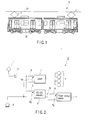
- FIG. 1 is an external view showing an electric motor car comprising an electric motor car control apparatus according to a first embodiment of the present invention;
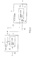
- FIG. 2 is a block diagram showing the arrangement of the electric motor car control apparatus;
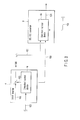
- FIG. 3 is a block diagram showing the arrangements of a VVVF inverter and a DC/DC converter and signal processing;
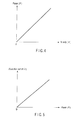
- FIG. 4 is a graph showing the relationship between the motor torque, velocity, and power of the electric motor car;
- FIG. 5 is a graph showing the relationship between an absorption current and power;
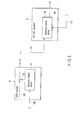
- FIG. 6 is a block diagram showing the arrangements of the VVVF inverter and DC/DC converter of an electric motor car control apparatus according to a second embodiment of the present invention;
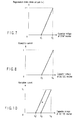
- FIG. 7 is a graph showing the relationship between a regeneration brake choke amount α and an operation start voltage set value (regeneration limiter start voltage value) V1 of a filter capacitor voltage value;
- FIG. 8 is a graph showing the relationship between an absorption current and a VVVF inverter capacitor voltage;
- FIG. 9 is a block diagram showing the arrangements of the VVVF inverter and DC/DC converter of an electric motor car control apparatus according to a third embodiment of the present invention;
- FIG. 10 is a graph showing the relationship between an absorption current and a DC/DC converter capacitor voltage;
- FIG. 11 is a block diagram showing the arrangements of the VVVF inverter and DC/DC converter of an electric motor car control apparatus according to a fourth embodiment of the present invention;
- FIG. 12 is a graph showing the relationship between an absorption current and a DC/DC converter capacitor voltage;
- FIG. 13 is a schematic view showing the arrangement of an electric motor car control apparatus according to a fifth embodiment of the present invention; and
- FIG. 14 is a schematic view showing the arrangement of an electric motor car control apparatus according to a sixth embodiment of the present invention.
- An embodiment of the present invention will be described below with reference to the views of the accompanying drawing.
-
- FIG. 1 is an external view showing an electric motor car comprising an electric motor car control apparatus according to a first embodiment of the present invention.
As shown in FIG. 1, anelectric motor car 10 receives electricity from anoverhead wire 21 through apantograph 1. The received electricity is input to an electric motorcar control apparatus 20. - FIG. 2 is a block diagram showing the arrangement of the electric motor
car control apparatus 20.
The electric motorcar control apparatus 20 comprises thepantograph 1, acontactor 2, afilter reactor 3, aVVVF inverter 4, a DC/DC converter 6, amotor 7, areactor 8, awheel 9, and apower storage device 11. Let VF, VD, and VE be the voltages to be respectively applied to theVVVF inverter 4, DC/DC converter 6, andpower storage device 11, and IE be the current flowing from the DC/DC converter 6 to thepower storage device 11.
The operation of the electric motorcar control apparatus 20 having the above arrangement will be described below. - FIG. 3 is a block diagram showing the arrangements of the
VVVF inverter 4 and DC/DC converter 6 and signal processing.
TheVVVF inverter 4 comprises a detection/control device 4a. The detection/control device 4a receives a VVVF inverter filtercapacitor voltage value 100, the velocity information of the electric motor car, the torque information of the motor, aregeneration brake command 105, and the like. The detection/control device 4a calculates regeneration brakechoke amount information 103 from the input information, and outputs, to themotor 7, a value obtained by subtracting the regeneration brakechoke amount information 103 from theregeneration brake command 105 as a motor torque command, thereby controlling themotor 7. - The detection/
control device 4a also calculates a power P from the input information by using the following equation, as shown in FIG. 4.
- The detection/
control device 4a outputspower P information 102 to a detection/control device 6a which the DC/DC converter 6 comprises. A DC/DC converter filtercapacitor voltage value 101 is input to the detection/control device 6a. In addition, acharging voltage value 110 is input from thepower storage device 11 to the detection/control device 6a. - The detection/
control device 6a calculates an absorption current I from the input information by using the following equation, as shown in, for example, FIG. 5.
- Upon calculating the absorption current I, the detection/
control device 6a outputs the absorption current I as anabsorption current command 104 to thepower storage device 11 to control thepower storage device 11. - With the above operation, the DC/DC converter is made to operate in accordance with various kinds of information detected by the VVVF inverter, thereby allowing the power storage device to effectively absorb power while keeping a balance between energy corresponding to a regeneration load shortage and absorbed energy.
- An electric motor car control apparatus according to a second embodiment of the present invention will be described next with reference to FIGS. 6 to 8. The same reference numbers as in the first embodiment denote the same parts in the second embodiment, and a detailed description thereof will be omitted.
- The second embodiment differs from the first embodiment in that a detection/
control device 4a of a VVVF inverter 4 outputs no information to a detection/control device 6a of a DC/DC converter 6, and an absorption start voltage value V3 of a DC/DC converter filtercapacitor voltage value 101 with respect to apower storage device 11 is set in advance to be equal to an operation start voltage set value (regeneration limiter start voltage value) V1 of a filtercapacitor voltage value 100. - FIG. 7 shows the relationship between a regeneration brake choke amount α and the operation start voltage set value (regeneration limiter start voltage value) VI of the filter
capacitor voltage value 100. As in the first embodiment, the DC/DC converter filtercapacitor voltage value 101 is input to the detection/control device 6a. - As shown in FIG. 8, the detection/
control device 6a of the DC/DC converter 6 sets the absorption start voltage value V3 of the DC/DC converter filtercapacitor voltage value 101 with respect to thepower storage device 11 to be equal to the value of V1. The detection/control device 6a then calculates an absorption current I on the basis of the DC/DC converter filtercapacitor voltage value 101, and outputs it as the absorptioncurrent command 104 to thepower storage device 11, thereby controlling thepower storage device 11. - The above operation makes it possible to ensure proper balance and cooperation between regeneration energy from the VVVF inverter and absorbed power by the DC/DC converter, thereby solving problems in terms of shortage or excess of absorbed energy.
- An electric motor control apparatus according to a third embodiment of the present invention will be described next with reference to FIGS. 9 and 10. The same reference numbers as in the first embodiment denote the same parts in the third embodiment, and a detailed description thereof will be omitted.
- The third embodiment differs from the first embodiment in that information output from a detection/
control device 4a of aVVVF inverter 4 to a detection/control device 6a of a DC/DC converter 6 is different from regeneration brakechoke amount information 103. - The DC/
DC converter 6 further comprises a predeterminedvalue detection unit 6b. The predeterminedvalue detection unit 6b outputs a correction command for correcting an absorption start voltage value V3 to a value V3' to the detection/control device 6a of the DC/DC converter 6 on the basis of the input regeneration brake choke amount information 103 (see FIG. 10). The predeterminedvalue detection unit 6b is set to output a correction command to the detection/control device 6a of the DC/DC converter 6 if, for example, α > 0 (regeneration brake choke amount α). - The detection/
control device 4a of theVVVF inverter 4 outputs the regeneration brake choke amount α as the regeneration brakechoke amount information 103 to the detection/control device 6a of the DC/DC converter 6. At the same time, an operation start voltage set value V1 is output to the detection/control device 6a of the DC/DC converter 6. As in the first embodiment, a DC/DC converter filtercapacitor voltage value 101 is input to the detection/control device 6a. - As shown in FIG. 10, the detection/
control device 6a of the DC/DC converter 6 sets and controls the absorption start voltage value V3 of the DC/DC converter filtercapacitor voltage value 101 for thepower storage device 11 to be equal to the value of V1 on the basis of the input regeneration brakechoke amount information 103, operation start voltage set value VI, and DC/DC converter filtercapacitor voltage value 101. The detection/control device 6a calculates an absorption current I on the basis of the DC/DC converter filtercapacitor voltage value 101, and outputs it as an absorptioncurrent command 112 to apower storage device 11, thereby controlling thepower storage device 11. - In the above state, if the predetermined
value detection unit 6b discriminates, on the basis of the regeneration brakechoke amount information 103 input to the predeterminedvalue detection unit 6b, that, for example, α > 0 (regeneration brake choke amount α), a correction command for correcting the absorption start voltage value V3 to the value V3' is output to the detection/control device 6a of the DC/DC converter 6. Upon receiving the correction command, the detection/control device 6a of the DC/DC converter 6 corrects the absorption start voltage value V3 to the value V3', as shown in FIG. 10. - That is, when regeneration limiter control is started upon a rise in the capacitor voltage of the
VVVF inverter 4, theVVVF inverter 4 outputs the regeneration brakechoke amount information 103 to the DC/DC converter 6. If the value of the regeneration brake choke amount exceeds a predetermined value, the DC/DC converter 6 corrects the absorption start voltage value V3 so as to decrease it to the value V3'. As a consequence, the capacitor voltage of the VVVF inverter becomes lower than the capacitor voltage of the DC/DC converter 6, and the operation of the DC/DC converter 6 is started to start absorption in thepower storage device 11. - With the above operation, if the capacitor voltage of the VVVF inverter is higher than that of the DC/DC converter, power absorption by the DC/DC converter by only VVVF regeneration limiter control can be prevented, thereby eliminating the problem of insufficient power absorption by performing regeneration limiter control operation using the VVVF inverter in synchronism with power absorption control operation by the DC/DC converter.
- An electric motor car control apparatus according to a fourth embodiment of the present invention will be described next with reference to FIGS. 11 and 12. The same reference numbers as in the third embodiment denote the same parts in the fourth embodiment, and a detailed description thereof will be omitted.
- The fourth embodiment differs from the third embodiment in that regeneration brake
choke amount information 103 output from a detection/control device 4a of aVVVF inverter 4 to a detection/control device 6a of a DC/DC converter 6 is a digital signal. - For this reason, the DC/
DC converter 6 does not comprise a predeterminedvalue detection unit 6b. In contrast, theVVVF inverter 4 comprises a predeterminedvalue detection unit 4b. - With the above arrangement, an
operation command 120 is transmitted as a digital signal from theVVVF inverter 4 to the DC/DC converter 6. - When regeneration limiter control is started upon a rise in the capacitor voltage of the
VVVF inverter 4, theVVVF inverter 4 transmits theoperation command 120 as a digital signal to the DC/DC converter 6 through the predeterminedvalue detection unit 4b. As shown in FIG. 12, upon receiving theoperation command 120, the DC/DC converter 6 calculates an absorption current 12, and outputs it as an absorptioncurrent command 114 to apower storage device 11, thereby controlling thepower storage device 11. - With the above operation, the start of regeneration limiter control using the
VVVF inverter 4 can be synchronized with the start of power absorption by the DC/DC converter 6, thereby preventing the occurrence of insufficient power absorption. In addition, using a digital signal as theoperation command 120 makes it possible to simplify the arrangement of the DC/DC converter 6. - An electric motor control apparatus according to a fifth embodiment of the present invention will be described next with reference to FIG. 13.
- In the fifth embodiment, as shown in FIG. 13, both the absorption
current command 104 in the first embodiment and the absorptioncurrent command 114 in the fourth embodiment are used. - The absorption
current command 104 and the absorptioncurrent command 114 can be switched by using aswitch 116, and each command can be output as an output absorptioncurrent command 130. If, for example, theswitch 116 switches the commands to output the absorptioncurrent command 104, the output absorptioncurrent command 130 becomes a power running command. If theswitch 116 switches the commands to output the absorptioncurrent command 114, the output absorptioncurrent command 130 becomes a regeneration command. The output absorptioncurrent command 130 is then output to apower storage device 11 to control it. - With the above operation, in addition to the effects of the first and fifth embodiments, the power storage device can be controlled by switching the embodiments of power running and regeneration.
- An electric motor control apparatus according to a sixth embodiment of the present invention will be described next with reference to FIG. 14.
- In the sixth embodiment, as shown in FIG. 14, both the absorption
current command 104 in the first embodiment and the absorptioncurrent command 112 in the second embodiment are used. - The absorption
current command 104 and the absorptioncurrent command 112 are subjected to addition processing by using anadder 118, and the resultant information is output as an output absorptioncurrent command 140. The output absorptioncurrent command 140 is then output to apower storage device 11 to control thepower storage device 11. - With the above operation, in addition to the effects of the first and second embodiments, the power storage device can be controlled on the basis of the absorption current commands in the first and second embodiments.
Claims (6)
- An electric motor control apparatus characterized by comprising an inverter (4) which drives a motor (7) of an electric motor car, storage means (11) for storing energy for the motor (7), and a converter (6) which is connected to the storage means (11),
the inverter (4) comprising detection means for detecting a power value of the motor, and transmission means for transmitting the power value detected by the detection means to the converter (6), and
the converter (6) comprising calculation means for receiving the power value transmitted by the transmission means, and calculating an absorption current on the basis of the received power value, and control means for controlling the storage means on the basis of the absorption current calculated by (11) the calculation means. - An apparatus according to claim 1, characterized in that the detection means detects a power value of the motor from velocity information of the electric motor car, motor torque information of the motor (7), and charging voltage of the storage means (11).
- An electric motor car control apparatus characterized by comprising an inverter (4) which drives a motor of an electric motor car, storage means (11) for storing energy for the motor (7), and a converter (6) which is connected to the storage means (11),
the converter makes an operation start voltage set value of a filter capacitor voltage upon regeneration limiter control by the inverter (4) coincide with an operation start voltage set value of a filter capacitor voltage of the converter (6). - An apparatus according to claim 3,
characterized in that the converter (6) controls the storage means (11) on the basis of a command from the inverter (4). - An apparatus according to claim 4, characterized in that the command is regeneration brake force choke amount information from the inverter (4), and the converter (6) corrects an operation start voltage set value of the filter capacitor voltage on the basis of the regeneration brake force choke amount information.
- An apparatus according to claim 4, characterized in that the command is an operation command from the inverter (4) on the basis of regeneration brake force choke amount information, the converter (6) calculates an absorption current to be output, and the storage means (11) is controlled by the calculated absorption current.
Applications Claiming Priority (1)
| Application Number | Priority Date | Filing Date | Title |
|---|---|---|---|
| JP2005136670A JP4643355B2 (en) | 2005-05-09 | 2005-05-09 | Electric vehicle control device |
Publications (2)
| Publication Number | Publication Date |
|---|---|
| EP1721775A2 true EP1721775A2 (en) | 2006-11-15 |
| EP1721775A3 EP1721775A3 (en) | 2016-10-26 |
Family
ID=36888948
Family Applications (1)
| Application Number | Title | Priority Date | Filing Date |
|---|---|---|---|
| EP06113492.0A Withdrawn EP1721775A3 (en) | 2005-05-09 | 2006-05-04 | Control apparatus for an eletric locomotive |
Country Status (4)
| Country | Link |
|---|---|
| US (1) | US7301293B2 (en) |
| EP (1) | EP1721775A3 (en) |
| JP (1) | JP4643355B2 (en) |
| CN (1) | CN1865038B (en) |
Cited By (5)
| Publication number | Priority date | Publication date | Assignee | Title |
|---|---|---|---|---|
| CN100528626C (en) * | 2007-06-07 | 2009-08-19 | 湖南牵引电气有限公司 | Regenerating braking energy inverting device for orbit traffic vehicle |
| EP2639097A3 (en) * | 2012-03-16 | 2015-08-12 | Kabushiki Kaisha Toshiba | Control device, control method and electric motor car |
| CN105857320A (en) * | 2016-06-01 | 2016-08-17 | 北京交通大学 | Energy management strategy of hybrid power bullet train set traction and transmission system |
| CN109733201A (en) * | 2019-01-16 | 2019-05-10 | 重庆交通大学 | Control method of regenerative braking energy absorption and utilization system for urban rail trains |
| CN109849678A (en) * | 2019-01-25 | 2019-06-07 | 云南航天神州汽车有限公司 | A kind of electric car regenerative braking safety control |
Families Citing this family (18)
| Publication number | Priority date | Publication date | Assignee | Title |
|---|---|---|---|---|
| JP4546988B2 (en) * | 2007-04-27 | 2010-09-22 | 株式会社日立製作所 | Control device for power converter |
| WO2011007430A1 (en) | 2009-07-15 | 2011-01-20 | 三菱電機株式会社 | Propulsion control device of electric car |
| WO2011021265A1 (en) * | 2009-08-17 | 2011-02-24 | 三菱電機株式会社 | Electric vehicle and power conversion device |
| KR101169343B1 (en) * | 2009-09-11 | 2012-07-30 | 한국철도기술연구원 | Restoration-electric power storage system of DC electric railway car |
| JP4869441B2 (en) * | 2011-03-23 | 2012-02-08 | 三菱電機株式会社 | Electric vehicle power converter |
| JP4948657B2 (en) * | 2011-03-23 | 2012-06-06 | 三菱電機株式会社 | Electric vehicle power converter |
| JP2011120475A (en) * | 2011-03-23 | 2011-06-16 | Mitsubishi Electric Corp | Power converter for electric vehicle |
| JP5172992B2 (en) * | 2011-06-02 | 2013-03-27 | ファナック株式会社 | Motor drive device including maximum output calculation unit of DC conversion unit |
| JP5777412B2 (en) * | 2011-06-03 | 2015-09-09 | 三菱電機株式会社 | Air-conditioning power supply system for multi-power rail vehicles |
| JP5523639B2 (en) * | 2012-01-12 | 2014-06-18 | 三菱電機株式会社 | Electric vehicle control device |
| CN103879295B (en) * | 2012-12-20 | 2016-08-10 | 中国北车股份有限公司 | Vehicle electric supply installation |
| DE102013202236B4 (en) * | 2013-02-12 | 2019-01-10 | Siemens Aktiengesellschaft | track vehicle |
| CN103350647B (en) * | 2013-06-24 | 2016-06-08 | 长春轨道客车股份有限公司 | A kind of motor train unit traction system of contact net and energy storage device hybrid power supply |
| CN103481787B (en) * | 2013-06-24 | 2015-12-23 | 长春轨道客车股份有限公司 | The motor train unit traction system of contact system, power bag and closed-center system hybrid power supply |
| JP6259778B2 (en) * | 2014-02-13 | 2018-01-10 | 株式会社日立製作所 | Railway vehicle drive system |
| CN105450137B (en) * | 2015-12-19 | 2018-12-21 | 太重(天津)重型装备科技开发有限公司 | The windrow swing mechanism control method of circular stockyard top heap side reclaimer |
| CN105774565A (en) * | 2016-03-01 | 2016-07-20 | 西南交通大学 | New brakes for rail vehicles |
| US10618547B2 (en) * | 2017-09-26 | 2020-04-14 | Steering Solutions Ip Holding Corporation | Regenerative current limiting of DC machines |
Family Cites Families (9)
| Publication number | Priority date | Publication date | Assignee | Title |
|---|---|---|---|---|
| JP3056898B2 (en) * | 1992-10-23 | 2000-06-26 | 株式会社東芝 | Electric car control device |
| JP3438796B2 (en) * | 1995-07-07 | 2003-08-18 | 富士電機株式会社 | DC electric vehicle drive control method |
| JP3413448B2 (en) * | 1997-02-14 | 2003-06-03 | 株式会社日立製作所 | Control device for brake chopper |
| JP2001226049A (en) * | 2000-02-15 | 2001-08-21 | Mitsubishi Electric Corp | Elevator control device |
| JP4283963B2 (en) * | 2000-02-28 | 2009-06-24 | 三菱電機株式会社 | Elevator control device |
| JP2002369308A (en) * | 2001-06-12 | 2002-12-20 | Railway Technical Res Inst | Electric rolling stock system |
| JP3890924B2 (en) | 2001-07-02 | 2007-03-07 | 株式会社明電舎 | Electric car drive system |
| JP2003199203A (en) * | 2001-12-25 | 2003-07-11 | Toshiba Corp | Method of protecting regenerative energy storage device and regenerative energy storage device |
| JP3795803B2 (en) * | 2001-12-25 | 2006-07-12 | 株式会社東芝 | Electric vehicle control device |
-
2005
- 2005-05-09 JP JP2005136670A patent/JP4643355B2/en not_active Expired - Fee Related
-
2006
- 2006-05-04 EP EP06113492.0A patent/EP1721775A3/en not_active Withdrawn
- 2006-05-08 US US11/429,076 patent/US7301293B2/en not_active Expired - Fee Related
- 2006-05-09 CN CN2006100803227A patent/CN1865038B/en not_active Expired - Fee Related
Non-Patent Citations (1)
| Title |
|---|
| None * |
Cited By (7)
| Publication number | Priority date | Publication date | Assignee | Title |
|---|---|---|---|---|
| CN100528626C (en) * | 2007-06-07 | 2009-08-19 | 湖南牵引电气有限公司 | Regenerating braking energy inverting device for orbit traffic vehicle |
| EP2639097A3 (en) * | 2012-03-16 | 2015-08-12 | Kabushiki Kaisha Toshiba | Control device, control method and electric motor car |
| CN105857320A (en) * | 2016-06-01 | 2016-08-17 | 北京交通大学 | Energy management strategy of hybrid power bullet train set traction and transmission system |
| CN105857320B (en) * | 2016-06-01 | 2019-03-01 | 北京交通大学 | Energy management strategy of traction drive system of hybrid electric trains |
| CN109733201A (en) * | 2019-01-16 | 2019-05-10 | 重庆交通大学 | Control method of regenerative braking energy absorption and utilization system for urban rail trains |
| CN109733201B (en) * | 2019-01-16 | 2021-10-19 | 重庆交通大学 | Control method of regenerative braking energy absorption and utilization system for urban rail trains |
| CN109849678A (en) * | 2019-01-25 | 2019-06-07 | 云南航天神州汽车有限公司 | A kind of electric car regenerative braking safety control |
Also Published As
| Publication number | Publication date |
|---|---|
| JP4643355B2 (en) | 2011-03-02 |
| US20060290318A1 (en) | 2006-12-28 |
| JP2006314182A (en) | 2006-11-16 |
| CN1865038B (en) | 2011-10-05 |
| EP1721775A3 (en) | 2016-10-26 |
| CN1865038A (en) | 2006-11-22 |
| US7301293B2 (en) | 2007-11-27 |
Similar Documents
| Publication | Publication Date | Title |
|---|---|---|
| EP1721775A2 (en) | Control apparatus for an eletric locomotive | |
| US9013135B2 (en) | Power converting apparatus for electric motor vehicle propulsion | |
| CA2806817C (en) | Electric vehicle propulsion control device and railway vehicle system | |
| JP5048384B2 (en) | Battery charger for railway vehicles | |
| EP2998150B1 (en) | Hybrid drive system | |
| KR101363701B1 (en) | Drive-control device for electric vehicle | |
| JP4561938B1 (en) | Electric vehicle drive control device | |
| RU2492072C1 (en) | Electric rolling stock electric power converter | |
| KR101171603B1 (en) | Power converter | |
| CN100550599C (en) | Electric car control device | |
| US7902791B2 (en) | Controller for variable speed alternating current motor | |
| JP5604984B2 (en) | Feeding voltage control method for electric railway system | |
| KR102603058B1 (en) | System and method for controlling charging power of ec0-friendly vehicle | |
| EP2434636B1 (en) | Generation system for rail cars | |
| JP2003291694A (en) | Power supply facility for alternate current electric railroad | |
| JP2011229249A (en) | Vehicle drive system | |
| GB2525279A (en) | Railway vehicle driving device | |
| JP6841627B2 (en) | Auxiliary power supply | |
| JP2012006565A (en) | Vehicle control device | |
| JP2011120475A (en) | Power converter for electric vehicle | |
| JP2011152040A (en) | Power converter of electric vehicle | |
| JPH0595605A (en) | Method and apparatus for driving motor |
Legal Events
| Date | Code | Title | Description |
|---|---|---|---|
| PUAI | Public reference made under article 153(3) epc to a published international application that has entered the european phase |
Free format text: ORIGINAL CODE: 0009012 |
|
| 17P | Request for examination filed |
Effective date: 20060504 |
|
| AK | Designated contracting states |
Kind code of ref document: A2 Designated state(s): AT BE BG CH CY CZ DE DK EE ES FI FR GB GR HU IE IS IT LI LT LU LV MC NL PL PT RO SE SI SK TR |
|
| AX | Request for extension of the european patent |
Extension state: AL BA HR MK YU |
|
| PUAL | Search report despatched |
Free format text: ORIGINAL CODE: 0009013 |
|
| AK | Designated contracting states |
Kind code of ref document: A3 Designated state(s): AT BE BG CH CY CZ DE DK EE ES FI FR GB GR HU IE IS IT LI LT LU LV MC NL PL PT RO SE SI SK TR |
|
| AX | Request for extension of the european patent |
Extension state: AL BA HR MK YU |
|
| RIC1 | Information provided on ipc code assigned before grant |
Ipc: B60L 7/10 20060101ALI20160919BHEP Ipc: B60L 9/18 20060101AFI20160919BHEP Ipc: B60L 11/18 20060101ALI20160919BHEP Ipc: B60L 7/18 20060101ALI20160919BHEP |
|
| AKX | Designation fees paid |
Designated state(s): DE FR |
|
| AXX | Extension fees paid |
Extension state: MK Extension state: YU Extension state: HR Extension state: AL Extension state: BA |
|
| RIC1 | Information provided on ipc code assigned before grant |
Ipc: B60L 9/18 20060101AFI20200316BHEP Ipc: B60L 7/10 20060101ALI20200316BHEP |
|
| GRAP | Despatch of communication of intention to grant a patent |
Free format text: ORIGINAL CODE: EPIDOSNIGR1 |
|
| INTG | Intention to grant announced |
Effective date: 20200428 |
|
| STAA | Information on the status of an ep patent application or granted ep patent |
Free format text: STATUS: THE APPLICATION IS DEEMED TO BE WITHDRAWN |
|
| 18D | Application deemed to be withdrawn |
Effective date: 20200909 |