EP1721577A1 - Endoskopisches Instrument - Google Patents
Endoskopisches Instrument Download PDFInfo
- Publication number
- EP1721577A1 EP1721577A1 EP06008584A EP06008584A EP1721577A1 EP 1721577 A1 EP1721577 A1 EP 1721577A1 EP 06008584 A EP06008584 A EP 06008584A EP 06008584 A EP06008584 A EP 06008584A EP 1721577 A1 EP1721577 A1 EP 1721577A1
- Authority
- EP
- European Patent Office
- Prior art keywords
- pull
- push rod
- medical instrument
- handle
- instrument according
- Prior art date
- Legal status (The legal status is an assumption and is not a legal conclusion. Google has not performed a legal analysis and makes no representation as to the accuracy of the status listed.)
- Granted
Links
- 230000033001 locomotion Effects 0.000 claims description 23
- 230000005540 biological transmission Effects 0.000 description 6
- 238000006073 displacement reaction Methods 0.000 description 3
- 238000006243 chemical reaction Methods 0.000 description 2
- 238000005452 bending Methods 0.000 description 1
- 230000015572 biosynthetic process Effects 0.000 description 1
- 230000006866 deterioration Effects 0.000 description 1
- 238000002674 endoscopic surgery Methods 0.000 description 1
- 230000000977 initiatory effect Effects 0.000 description 1
- 238000004519 manufacturing process Methods 0.000 description 1
Images


Classifications
-
- A—HUMAN NECESSITIES
- A61—MEDICAL OR VETERINARY SCIENCE; HYGIENE
- A61B—DIAGNOSIS; SURGERY; IDENTIFICATION
- A61B17/00—Surgical instruments, devices or methods
- A61B17/28—Surgical forceps
- A61B17/29—Forceps for use in minimally invasive surgery
-
- A—HUMAN NECESSITIES
- A61—MEDICAL OR VETERINARY SCIENCE; HYGIENE
- A61B—DIAGNOSIS; SURGERY; IDENTIFICATION
- A61B17/00—Surgical instruments, devices or methods
- A61B17/04—Surgical instruments, devices or methods for suturing wounds; Holders or packages for needles or suture materials
- A61B17/0483—Hand-held instruments for holding sutures
-
- A—HUMAN NECESSITIES
- A61—MEDICAL OR VETERINARY SCIENCE; HYGIENE
- A61B—DIAGNOSIS; SURGERY; IDENTIFICATION
- A61B17/00—Surgical instruments, devices or methods
- A61B17/16—Instruments for performing osteoclasis; Drills or chisels for bones; Trepans
- A61B17/1604—Chisels; Rongeurs; Punches; Stamps
- A61B17/1606—Chisels; Rongeurs; Punches; Stamps of forceps type, i.e. having two jaw elements moving relative to each other
- A61B17/1608—Chisels; Rongeurs; Punches; Stamps of forceps type, i.e. having two jaw elements moving relative to each other the two jaw elements being linked to two elongated shaft elements moving longitudinally relative to each other
-
- A—HUMAN NECESSITIES
- A61—MEDICAL OR VETERINARY SCIENCE; HYGIENE
- A61B—DIAGNOSIS; SURGERY; IDENTIFICATION
- A61B17/00—Surgical instruments, devices or methods
- A61B2017/00681—Aspects not otherwise provided for
- A61B2017/00685—Archimedes screw
-
- A—HUMAN NECESSITIES
- A61—MEDICAL OR VETERINARY SCIENCE; HYGIENE
- A61B—DIAGNOSIS; SURGERY; IDENTIFICATION
- A61B17/00—Surgical instruments, devices or methods
- A61B17/28—Surgical forceps
- A61B17/29—Forceps for use in minimally invasive surgery
- A61B2017/2926—Details of heads or jaws
- A61B2017/2932—Transmission of forces to jaw members
- A61B2017/2933—Transmission of forces to jaw members camming or guiding means
-
- A—HUMAN NECESSITIES
- A61—MEDICAL OR VETERINARY SCIENCE; HYGIENE
- A61B—DIAGNOSIS; SURGERY; IDENTIFICATION
- A61B17/00—Surgical instruments, devices or methods
- A61B17/28—Surgical forceps
- A61B17/29—Forceps for use in minimally invasive surgery
- A61B2017/2926—Details of heads or jaws
- A61B2017/2932—Transmission of forces to jaw members
- A61B2017/2933—Transmission of forces to jaw members camming or guiding means
- A61B2017/2936—Pins in guiding slots
Definitions
- the invention relates to a medical instrument with a hollow shaft, at the proximal end of which a handle consisting of at least two handle parts is arranged and at the distal end of which consists of at least two jaws tool is arranged, wherein at least one jaw part of the tool for opening and closing over a pivotable designed grip part of the handle relative to the at least one other jaw part of the tool is adjustable and the at least one adjustable jaw part and the corresponding, serving for adjusting the jaw part handle part of the handle via an axially displaceable in the hollow shaft mounted pull / push rod are connected together ,
- the invention has for its object to provide a medical instrument of the aforementioned type, in which the conversion of the axial movement of the push / pull rod easily and reliably into the rotational movement of the adjustable jaw part.
- the solution to this problem is inventively characterized in that the axially displaceable mounted in the hollow shaft pull / push rod via at least one helical guideway in a rotational movement about its longitudinal axis can be transferred.
- the inventive design of the at least one helical guideway it is possible in a structurally simple manner to convert the axial movement of the pull / push rod in a rotational movement of the pull / push rod, which is particularly advantageous for medical instruments, the jaws angled laterally to the longitudinal axis of the shaft are aligned.
- the adjustable jaw member is mounted at the distal end of the pull / push rod.
- the helical guideway is formed on the pull / push rod and the pull / push rod is advantageously designed in several parts, wherein at least two sections of the pull / push rod via helically shaped end portions are connected to each other.
- This embodiment of the invention in which two parts of the pull / push rod are screwed together via helically shaped end portions, represents a particularly space-saving and structurally simple way of movement implementation according to the invention.
- the pull / push rod is formed in two parts, wherein the proximal portion of the pivotable handle portion of the handle can be fixed and at the distal end of the distal portion of the adjustable jaw part of the tool is arranged.
- the hollow shaft according to the invention is closable on the distal side.
- the handle connected to the portion of the pull / push rod is mounted non-rotatably about its longitudinal axis on the pivotable handle portion of the handle to the rotational movement of the pull / push rod exclusively on the provided with the adjustable jaw portion of the train - / Push rod to transfer.
- the helical guideway be formed as a helical groove in the lateral surface of the pull / push rod, which cooperates with a rigid abutment disposed on the inside of the hollow shaft.
- This rotation of the pull / push rod initiating rigid abutment can be inventively designed as engaging in the helical groove bolts or as corresponding to the helical groove helical counter contour, the design of the intermeshing helical contours is characterized by lower friction losses.
- the helical guide track is formed on the inside of the hollow shaft.
- the helical guideway is formed as a helical groove on the inside of the hollow shaft, which cooperates with a rigid abutment disposed on the lateral surface of the push / pull rod, said rigid abutment preferably engaging as in the helical groove Bolt is formed.
- the pull / push rod is freely rotatably mounted about its longitudinal axis on the pivotable handle portion of the handle to allow rotation of the starting against the rigid abutment pull / push rod about its longitudinal axis, if this on the pivotable Handle is displaced in the axial direction.
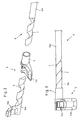
- FIG. 1 shows a side view of a medical instrument 1, the power transmission mechanism of which can be used in a variety of ways, such as stamping, scissors, needle holders, drum instruments and the like.
- the medical instrument 1 essentially consists of a hollow shaft 2, on the proximal end of which a handle 3 a, consisting of a rigid grip part 3 a and a handle part 3 b pivotable about a pivot axis 4, is disposed.
- a tool 5 is arranged, which consists in the illustrated embodiment (Fig. 2 and 3) of a pivotable jaw part 5a and a rigidly connected to the shaft 2 jaw part 5b.
- FIGS. 2 to 6 show that the jaw parts 5a, 5b of the tool 5 are bent laterally with respect to the longitudinal axis of the shaft 2.
- the jaws 5a, 5b are each aligned at right angles to the longitudinal axis of the instrument shaft. Other angular positions between 0 ° and 90 ° and beyond, however, are also practicable.
- the pivotable jaw part 5a is mounted at the distal end of a pull / push rod 6 which is mounted in the hollow shaft 2 on the proximal side with the pivotable grip part 3b of the handle 3 by the pivoting of the handle part 3b, the pivotable jaw part 5a can be transferred from a closed position to an open position or vice versa.
- the pull / push rods 6 are each constructed in several parts, consisting of individual sections 6a.
- the mutually facing ends of the sections 6a are formed as a helical so that in each case two helical guideways 7 are screwed into one another, as shown in the figures Fig. 3 and 5 can be seen.
- the proximal portion 6a of the pull / push rod 6 can be additionally extended and / or alternatively extended to the illustrated embodiment, depending on the respective handle 3 to be used on the proximal side and shaped
- the distal end of the hollow shaft 2 is closed in order to prevent axial displacement of the section 6a of the pull / push rod 6 provided with the pivotable jaw part 5a.
- this axial displacement of the proximal section 6a of the pull / push rod 6 causes the helical guideways 7 of the two sections 6a to be screwed into one another or one another
- the proximal portion 6a of the pull / push rod 6 is mounted non-rotatably on the pivotable handle part 3b of the handle 3
- the interlocking or disassembling of the helical guideways 7 of the two sections 6a causes the distal, with the pivotable jaw part 5a provided portion 6a of the pull / push rod 6 a rotational movement about his Performs longitudinal axis, whereby the pivotable jaw part 5a is adjustable between an open and a closed position.
- FIGS. 2 and 4 differ from one another in that the two helical guideways 7 of the sections 6a of the pull / push rod 6 have one and a half threads in the embodiment according to FIGS. 2 and 3, while in the embodiment according to FIG 4 and 5, the guideways 7 of each section 6a have only half a thread.
- the helical guideways 7 can be designed as a helical groove in the lateral surface of the pull / push rod 6, as shown in FIG is shown, or form as a helical groove on the inside of the hollow shaft 2, wherein for generating the rotational movement on the inside of the hollow shaft 2 or on the lateral surface of the pull / push rod 6 rigid abutment 8 are arranged, with the respective helical grooves interact.
- the abutment 8 is formed as arranged on the inside of the hollow shaft 2 and engaging in the helical groove bolts.
- the pull / push rod 6 is freely rotatable about its longitudinal axis on the pivotable handle part 3b of the handle 3, so that the pull / push rod 6 when starting against the respective abutment due to the operation of the pivotable handle part 3b can rotate about its longitudinal axis.
- a medical instrument as described above is distinguished by the fact that, with a simple structural design and simple handling, a uniform and reliable conversion of the axial movement transmitted by the pivotable grip part 3b to the pull / push rod 6 into a rotational movement of the pivotable jaw part 5a is largely free of play Power transmission guaranteed.
Landscapes
- Health & Medical Sciences (AREA)
- Surgery (AREA)
- Life Sciences & Earth Sciences (AREA)
- Biomedical Technology (AREA)
- Medical Informatics (AREA)
- Veterinary Medicine (AREA)
- Public Health (AREA)
- Engineering & Computer Science (AREA)
- General Health & Medical Sciences (AREA)
- Heart & Thoracic Surgery (AREA)
- Nuclear Medicine, Radiotherapy & Molecular Imaging (AREA)
- Molecular Biology (AREA)
- Animal Behavior & Ethology (AREA)
- Dentistry (AREA)
- Oral & Maxillofacial Surgery (AREA)
- Orthopedic Medicine & Surgery (AREA)
- Ophthalmology & Optometry (AREA)
- Surgical Instruments (AREA)
Abstract
Description
- Die Erfindung betrifft ein medizinisches Instrument mit einem hohlen Schaft, an dessen proximalem Ende eine aus mindestens zwei Griffteilen bestehende Handhabe angeordnet ist und an dessen distalem Ende ein aus mindestens zwei Maulteilen bestehendes Werkzeug angeordnet ist, wobei mindestens ein Maulteil des Werkzeugs zum Öffnen und Schließen über ein verschwenkbar ausgebildetes Griffteil der Handhabe gegenüber dem mindestens einen anderen Maulteil des Werkzeugs verstellbar ist und das mindestens eine verstellbare Maulteil und das entsprechende, zum Verstellen des Maulteils dienende Griffteil der Handhabe über eine axial verschiebbare in dem hohlen Schaft gelagerte Zug-/Druckstange miteinander verbunden sind.
- Gattungsgemäße medizinische Instrumente, bei denen das bewegliche Maulteil ausgehend von einem verschwenkbaren Griffteil der Handhabe über ein Zug/Druckelement betätigbar ist, finden insbesondere in der endoskopischen Chirurgie vielseitige Verwendung, beispielsweise als Stanzen, Scheren, Nadelhalter, Fassinstrumente und dergleichen. Bei diesen bekannten Instrumenten sind die das Werkzeug bildenden Maulteile in der Regel in Längsrichtung des Instrumentenschaftes angeordnet, so dass mit diesen Instrumenten nur Operationsgebiete erreichbar sind, die direkt zugänglich im wesentlichen vor der Instrumentenspitze angeordnet sind. Da aber manche Operationsgebiete nicht auf direktem geradlinigen Weg zugänglich sind, sind diese bekannten Instrumente für diese Zwecke gar nicht, oder nur bedingt geeignet.
- Weiterhin sind gattungsgemäße medizinische Instrumente bekannt, bei denen die Maulteile des Werkzeugs seitlich abgewinkelt zur Längsachse des Schaftes ausgerichtet sind. Da bei diesen Instrumenten das verschwenkbare Maulteil des Werkzeugs beim Öffnen und Schließen, relativ zur Axialbewegung der Zug-/Druckstange betrachtet, eine Drehbewegung ausführt, ist es notwendig, die über die Bewegung der Handhabe initiierte Axialbewegung der Zug-/Druckstange in eine Drehbewegung umzusetzen. Hierzu ist es aus der Praxis bekannt, die Handhabe und die Zug-/Druckstange über ein Zahnradgetriebe miteinander zu koppeln. Diese Ausgestaltung ist zwar relativ einfach herzustellen, jedoch genügt die Kraftübertragung auf das Werkzeugs nicht allen operativen Anforderungen.
- Aus der
DE 103 27 655 A1 ist ein gattungsgemäßes medizinisches Instrument mit seitlich zur Längsachse des Schaftes abgewinkelten Maulteilen bekannt, bei dem die Bewegungsumsetzung über einen Übertragungshebel erfolgt, der einerseits an der Zug-/Druckstange gelagert ist und andererseits mit dem verstellbaren Maulteil des Werkzeugs verbunden ist. Diese konstruktive Umsetzung der Axialbewegung in eine Drehbewegung hat sich in der Praxis durchaus bewährt, jedoch ist diese Ausgestaltung konstruktiv sehr aufwendig. - Davon ausgehend liegt der Erfindung die Aufgabe zugrunde, ein medizinisches Instrument der eingangs genannten Art bereitzustellen, bei dem die Umsetzung der Axialbewegung der Zug-/Druckstange in die Drehbewegung des verstellbaren Maulteils einfach und zuverlässig erfolgt.
- Die Lösung dieser Aufgabenstellung ist erfindungsgemäß dadurch gekennzeichnet, dass die axial verschiebbar in dem hohlen Schaft gelagerte Zug-/Druckstange über mindestens eine wendelförmige Führungsbahn in eine Rotationsbewegung um ihre Längsachse überführbar ist.
- Durch die erfindungsgemäße Ausbildung der mindestens einen wendelförmigen Führungsbahn ist es auf konstruktiv einfache Weise möglich, die Axialbewegung der Zug-/Druckstange in eine Rotationsbewegung der Zug-/Druckstange umzuwandeln, was insbesondere für medizinische Instrumente vorteilhaft ist, deren Maulteile seitlich abgewinkelt zur Längsachse des Schaftes ausgerichtet sind.
- Um die in die Zug-/Druckstange übertragene Drehbewegung direkt und möglichst ohne eine Verschlechterung der Kraftübertragung auf das Werkzeug übertragen zu können, wird erfindungsgemäß vorgeschlagen, dass das verstellbare Maulteil am distalen Ende der Zug-/Druckstange gelagert ist.
- Gemäß einer ersten konstruktiven Ausführungsform der Erfindung wird vorgeschlagen, dass die wendelförmige Führungsbahn an der Zug-/Druckstange ausgebildet ist und die Zug-/Druckstange vorteilhafterweise mehrteilig ausgebildet ist, wobei wenigstens zwei Teilstücke der Zug-/Druckstange über wendelförmig ausgebildete Endbereiche miteinander verbindbar sind. Diese erfindungsgemäße Ausgestaltungsform, bei der zwei Teilstücke der Zug-/Druckstange über wendelförmig ausgebildete Endbereiche miteinander verschraubt sind, stellt eine besonders platzsparende und konstruktiv einfache Möglichkeit der erfindungsgemäßen Bewegungsumsetzung dar.
- Mit einer praktischen Ausführungsform der Erfindung wird vorgeschlagen, dass die Zug-/Druckstange zweiteilig ausgebildet ist, wobei das proximale Teilstück am verschwenkbaren Griffteil der Handhabe festlegbar ist und am distalen Ende des distalen Teilstücks das verstellbare Maulteil des Werkzeugs angeordnet ist.
- Um zu verhindern, dass bei der mehrteiligen Ausgestaltung der Zug-/Druckstange das mit dem verstellbaren Maulteil versehene Teilstück der Zug-/Druckstange zusätzlich zu der eingeleiteten Drehbewegung auch in Axialrichtung verlagert werden kann, ist der hohle Schaft erfindungsgemäß distalseitig verschließbar.
- Weiterhin wird mit der Erfindung vorgeschlagen, dass das mit der Handhabe verbundene Teilstück der Zug-/Druckstange unverdrehbar um seine Längsachse am verschwenkbaren Griffteil der Handhabe gelagert ist, um die Drehbewegung der Zug-/Druckstange ausschließlich auf das mit dem verstellbaren Maulteil versehenen Teilstück der Zug-/Druckstange zu übertragen.
- Gemäß einer zweiten konstruktiven Ausführungsform der Erfindung wird vorgeschlagen, dass die wendelförmige Führungsbahn als wendelförmige Nut in der Mantelfläche der Zug-/Druckstange ausgebildet ist, die mit einem an der Innenseite des hohlen Schaftes angeordneten starren Widerlager zusammenwirkt.
- Dieses die Drehbewegung der Zug-/Druckstange einleitende starre Widerlager kann erfindungsgemäß als in die wendelförmige Nut eingreifender Bolzen oder als mit der wendelförmigen Nut korrespondierende wendelförmige Gegenkontur ausgebildet sein, wobei die Ausgestaltung der ineinandergreifenden wendelförmige Konturen sich durch geringere Reibungsverluste auszeichnet.
- Gemäß einer dritten konstruktiven Ausführungsform der Erfindung wird vorgeschlagen, dass die wendelförmige Führungsbahn an der Innenseite des hohlen Schaftes ausgebildet ist.
- Gemäß einer praktischen Ausführungsform dieser konstruktiven Ausgestaltung ist die wendelförmige Führungsbahn als wendelförmige Nut an der Innenseite des hohlen Schaftes ausgebildet ist, die mit einem auf der Mantelfläche der Zug-/Druckstange angeordneten starren Widerlager zusammenwirkt, wobei dieses starre Widerlager vorzugsweise als in die wendelförmige Nut eingreifender Bolzen ausgebildet ist.
- Schließlich wird mit der Erfindung vorgeschlagen, dass die Zug-/Druckstange frei drehbar um ihre Längsachse am verschwenkbaren Griffteil der Handhabe gelagert ist, um ein Drehen der gegen das starre Widerlager anlaufenden Zug-/Druckstange um ihre Längsachse zu ermöglichen, wenn diese über das verschwenkbare Griffteil in axialer Richtung verlagert wird.
- Weitere Merkmale und Vorteile der Erfindung ergeben sich anhand der Beschreibung der zugehörigen Zeichnung, in der drei Ausführungsbeispiele eines erfindungsgemäßen medizinischen Instruments nur beispielhaft schematisch dargestellt sind. In der Zeichnung zeigt:
- Fig. 1
- eine Seitenansicht eines erfindungsgemäßen medizinischen Instruments;
- Fig. 2
- eine ausschnittweise perspektivische Explosionsdarstellung des distalen Endes eines medizinischen Instruments gemäß einer ersten erfindungsgemäßen Ausführungsform;
- Fig. 3
- eine Draufsicht auf die Ausführungsform gemäß Fig. 2, jedoch im zusammengesetzten Zustand;
- Fig. 4
- eine Darstellung gemäß Fig. 2, jedoch eine zweite erfindungsgemäße Ausführungsform darstellend;
- Fig. 5
- eine perspektivische Ansicht der Ausführungsform gemäß Fig. 4, jedoch im zusammengesetzten Zustand und
- Fig.6
- eine perspektivische Ansicht gemäß Fig. 5, jedoch eine dritte erfindungsgemäße Ausführungsform darstellend.
- Die Abbildung Fig. 1 zeigt eine Seitenansicht eines medizinischen Instruments 1, dessen Kraftübertragungsmechanismus vielseitig verwendet werden kann, wie beispielsweise für Stanzen, Scheren, Nadelhalter, Fassinstrumente und dergleichen.
- Das medizinische Instrument 1 besteht im wesentlichen aus einem hohlen Schaft 2, an dessen proximalem Ende eine aus einem starren Griffteil 3a und einem gegenüber dem starren Griffteil 3a um eine Schwenkachse 4 verschwenkbaren Griffteil 3b bestehende Handhabe 3 angeordnet ist. Am distalen Ende des Schaftes 2 ist ein Werkzeug 5 angeordnet, welches beim dargestellten Ausführungsbeispiel (Fig. 2 und 3) aus einem verschwenkbaren Maulteil 5a und einem starr mit dem Schaft 2 verbundenen Maulteil 5b besteht.
- Die Darstellungen der Abbildungen Fig. 2 bis 6 zeigen, dass die Maulteile 5a, 5b des Werkzeugs 5 bezüglich der Längsachse des Schaftes 2 seitlich abwinkelt ausgebildet sind. Bei den dargestellten Ausführungsbeispielen sind die Maulteile 5a, 5b jeweils rechtwinklig zur Längsachse des Instrumentenschaftes ausgerichtet. Andere Winkellagen zwischen 0° und 90° und auch darüber hinaus sind jedoch auch praktikabel.
- Durch die Abwinklung des Werkzeugs 5 gegenüber dem Schaft 2 ist es möglich, mit einem solchermaßen ausgebildeten medizinisches Instrument 1 auch schwer und nicht auf einem direkten geradlinigen Weg zugängliche Operationsgebiete zu erreichen.
- Wie weiterhin aus den Darstellungen gemäß Fig. 2 bis 6 ersichtlich, ist das verschwenkbare Maulteil 5a am distalen Ende einer Zug-/Druckstange 6 gelagert, welche in dem hohlen Schaft 2 gelagert proximalseitig so mit dem verschwenkbaren Griffteil 3b der Handhabe 3 verbunden ist, dass durch das Verschwenken des Griffteils 3b das verschwenkbare Maulteil 5a von einer geschlossenen Stellung in eine geöffnete Stellung bzw. umgekehrt überführt werden kann.
- Um die über die Betätigung des verschwenkbaren Griffteils 3b der Handhabe 3 auf die Zug-/Druckstange 6 übertragene Verschiebung in Axialrichtung in eine Drehbewegung zum Verschwenken des Maulteils 5a des Werkzeugs 5 umwandeln zu können, ist an der Zug-/Druckstange 6 eine wendelförmige Führungsbahn 7 ausgebildet.
- Bei den in den Abbildungen Fig. 2 bis 5 dargestellten Ausführungsformen sind die Zug-/Druckstangen 6 jeweils mehrteilig, aus einzelnen Teilstücken 6a bestehend aufgebaut. Die einander zugewandten Enden der Teilstücke 6a sind als wendelförmige so ausgebildet, dass jeweils zwei wendelförmige Führungsbahnen 7 ineinander verschraubbar sind, wie dies den Abbildungen Fig. 3 und 5 zu entnehmen ist. Das proximale Teilstück 6a der Zug-/Druckstange 6 kann ergänzend und/oder alternativ zu der dargestellten Ausführungsform in Abhängigkeit von der jeweils zu verwendenden Handhabe 3 proximalseitig beliebig verlängert und ausgeformt werden
- Im zusammengesetzten Zustand wird das distale Ende des hohlen Schaftes 2 verschlossen, um eine Axialverschiebung des mit dem verschwenkbaren Maulteil 5a versehenen Teilstück 6a der Zug-/Druckstange 6 zu verhindern. Sobald über das verschwenkbare Griffteil 3b der Handhabe 3 die Zug-/Druckstange 6 in Axialrichtung im hohlen Schaft 2 verschoben wird, bewirkt diese Axialverlagerung des proximalen Teilstücks 6a der Zug-/Druckstange 6 ein ineinander- oder auseinaderschrauben der wendelförmigen Führungsbahnen 7 der beiden Teilstücke 6a der Zug-/Druckstange 6. Da das proximale Teilstück 6a der Zug-/Druckstange 6 verdrehfest am verschwenkbaren Griffteil 3b der Handhabe 3 gelagert ist, bewirkt das Ineinander- oder Auseinaderschrauben der wendelförmigen Führungsbahnen 7 der beiden Teilstücke 6a, dass das distale, mit dem verschwenkbaren Maulteil 5a versehene Teilstück 6a der Zug-/Druckstange 6 eine Rotationsbewegung um seine Längsachse ausführt, wodurch das verschwenkbaren Maulteil 5a zwischen einer geöffneten und einer geschlossenen Stellung verstellbar ist.
- Die in den Abbildungen Fig. 2 und 4 dargestellten Ausführungsbeispiele unterscheiden sich dadurch voneinander, dass die beiden wendelförmigen Führungsbahnen 7 der Teilstücke 6a der Zug-/Druckstange 6 bei der Ausführungsform gemäß Fig. 2 und 3 eineinhalb Gewindegänge aufweist, während bei der Ausführungsform gemäß Fig. 4 und 5 die Führungsbahnen 7 jedes Teilstücks 6a nur einen halben Gewindegang aufweisen.
- Alternativ zu den in den Abbildungen Fig. 2 bis 5 dargestellten Ausführungsformen zur Ausbildung bzw. Anordnung der wendelförmigen Führungsbahnen 7 ist es auch möglich, die wendelförmigen Führungsbahnen 7 als wendelförmige Nut in der Mantelfläche der Zug-/Druckstange 6, wie dies in Fig. 6 dargestellt ist, oder als wendelförmige Nut an der Innenseite des hohlen Schaftes 2 auszubilden, wobei zur Erzeugung der Rotationsbewegung an der Innenseite des hohlen Schaftes 2 oder auf der Mantelfläche der Zug-/Druckstange 6 starre Widerlager 8 angeordnet sind, die mit den jeweiligen wendelförmige Nuten zusammenwirken.
- Bei der in Fig. 6 dargestellten Ausführungsform ist das Widerlager 8 als an der Innenseite des hohlen Schaftes 2 angeordneter und in die wendelförmige Nut eingreifender Bolzen ausgebildet.
- Voraussetzung bei dieser Art der Ausgestaltung ist, dass die Zug-/Druckstange 6 frei drehbar um ihre Längsachse am verschwenkbaren Griffteil 3b der Handhabe 3 gelagert ist, damit sich die Zug-/Druckstange 6 beim Anlaufen gegen das jeweilige Widerlager aufgrund der Betätigung des verschwenkbaren Griffteil 3b um ihre Längsachse drehen kann.
- Ein wie voran beschriebenes medizinisches Instrument zeichnet sich dadurch aus, dass es bei einfachem konstruktivem Aufbau und einfacher Handhabung eine gleichmäßige und sichere Umsetzung der durch das verschwenkbare Griffteil 3b auf die Zug-/Druckstange 6 übertragenen Axialbewegung in eine Rotationsbewegung des verschwenkbaren Maulteils 5a bei weitestgehend spielfreier Kraftübertragung gewährleistet.
-
- 1
- medizinisches Instrument
- 2
- Schaft
- 3
- Handhabe
- 3a
- starres Griffteil
- 3b
- verschwenkbares Griffteil
- 4
- Schwenkachse
- 5
- Werkzeug
- 5a
- verschwenkbares Maulteil
- 5b
- starres Maulteil
- 6
- Zug-/Druckstange
- 6a
- Teilstück
- 7
- Führungsbahn
- 8
- Widerlager
Claims (15)
- Medizinisches Instrument mit einem hohlen Schaft (2), an dessen proximalem Ende eine aus mindestens zwei Griffteilen (3a, 3b) bestehende Handhabe (3) angeordnet ist und an dessen distalem Ende ein aus mindestens zwei Maulteilen (5a, 5b) bestehendes Werkzeug (5) angeordnet ist, wobei mindestens ein Maulteil (5a) des Werkzeugs (5) zum Öffnen und Schließen über ein verschwenkbar ausgebildetes Griffteil (3b) der Handhabe (3) gegenüber dem mindestens einen anderen Maulteil (5b) des Werkzeugs (5) verstellbar ist und das mindestens eine verstellbare Maulteil (5a) und das entsprechende, zum Verstellen des Maulteils (5a) dienende Griffteil (3b) der Handhabe (3) über eine axial verschiebbare in dem hohlen Schaft (2) gelagerte Zug-/Druckstange (6) miteinander verbunden sind,
dadurch gekennzeichnet,
dass die axial verschiebbar in dem hohlen Schaft (2) gelagerte Zug-/Druckstange (6) über mindestens eine wendelförmige Führungsbahn (7) in eine Rotationsbewegung um ihre Längsachse überführbar ist. - Medizinisches Instrument nach Anspruch 1, dadurch gekennzeichnet, dass das verstellbare Maulteil (5a) am distalen Ende der Zug-/Druckstange (6) gelagert ist.
- Medizinisches Instrument nach Anspruch 1 oder 2, dadurch gekennzeichnet, dass die wendelförmige Führungsbahn (7) an der Zug-/Druckstange (6) ausgebildet ist.
- Medizinisches Instrument nach Anspruch 3, dadurch gekennzeichnet, dass die Zug-/Druckstange (6) mehrteilig ausgebildet ist, wobei wenigstens zwei Teilstücke (6a) der Zug-/Druckstange (6) über wendelförmig ausgebildete Endbereiche miteinander verbindbar sind.
- Medizinisches Instrument nach Anspruch 4, dadurch gekennzeichnet, dass die Zug-/Druckstange (6) zweiteilig ausgebildet ist, wobei das proximale Teilstück (6a) am verschwenkbaren Griffteil (3b) der Handhabe (3) festlegbar ist und am distalen Ende des distalen Teilstücks (6a) das verstellbare Maulteil (5a) des Werkzeugs (5) angeordnet ist.
- Medizinisches Instrument nach Anspruch 4 oder 5, dadurch gekennzeichnet, dass der hohle Schaft (2) distalseitig verschließbar ist.
- Medizinisches Instrument nach einem der Ansprüche 4 bis 6, dadurch gekennzeichnet, dass das mit der Handhabe (3) verbundene Teilstück (6a) der Zug-/Druckstange (6) unverdrehbar um seine Längsachse am verschwenkbaren Griffteil (3b) der Handhabe (3) gelagert ist.
- Medizinisches Instrument nach Anspruch 3, dadurch gekennzeichnet, dass die wendelförmige Führungsbahn (7) als wendelförmige Nut in der Mantelfläche der Zug-/Druckstange (6) ausgebildet ist, die mit einem an der Innenseite des hohlen Schaftes (2) angeordneten starren Widerlager (8) zusammenwirkt.
- Medizinisches Instrument nach Anspruch 8, dadurch gekennzeichnet, dass das an der Innenseite des hohlen Schaftes (2) angeordnete starre Widerlager (8) als in die wendelförmige Nut eingreifender Bolzen ausgebildet ist.
- Medizinisches Instrument nach Anspruch 8, dadurch gekennzeichnet, dass das an der Innenseite des hohlen Schaftes (2) angeordnete starre Widerlager (8) als mit der wendelförmigen Nut korrespondierende wendelförmige Gegenkontur ausgebildet ist.
- Medizinisches Instrument nach Anspruch 1 oder 2, dadurch gekennzeichnet, dass die wendelförmige Führungsbahn (7) an der Innenseite des hohlen Schaftes (2) ausgebildet ist.
- Medizinisches Instrument nach Anspruch 11, dadurch gekennzeichnet, dass die wendelförmige Führungsbahn (7) als wendelförmige Nut an der Innenseite des hohlen Schaftes (2) ausgebildet ist, die mit einem auf der Mantelfläche der Zug-/Druckstange (6) angeordneten starren Widerlager (8) zusammenwirkt.
- Medizinisches Instrument nach Anspruch 12, dadurch gekennzeichnet, dass das auf der Mantelfläche der Zug-/Druckstange (8) angeordnete starre Widerlager (8) als in die wendelförmige Nut eingreifender Bolzen ausgebildet ist.
- Medizinisches Instrument nach einem der Ansprüche 8 bis 13, dadurch gekennzeichnet, dass die Zug-/Druckstange (6) frei drehbar um ihre Längsachse am verschwenkbaren Griffteil (3b) der Handhabe (3) gelagert ist.
- Medizinisches Instrument nach einem der Ansprüche 1 bis 14, dadurch gekennzeichnet, dass die Maulteile (5a, 5b) seitlich abgewinkelt zur Längsachse des Schaftes (2) ausgerichtet sind.
Applications Claiming Priority (1)
| Application Number | Priority Date | Filing Date | Title |
|---|---|---|---|
| DE102005021234A DE102005021234A1 (de) | 2005-05-09 | 2005-05-09 | Medizinisches Instrument |
Publications (2)
| Publication Number | Publication Date |
|---|---|
| EP1721577A1 true EP1721577A1 (de) | 2006-11-15 |
| EP1721577B1 EP1721577B1 (de) | 2008-04-02 |
Family
ID=36832258
Family Applications (1)
| Application Number | Title | Priority Date | Filing Date |
|---|---|---|---|
| EP06008584A Expired - Lifetime EP1721577B1 (de) | 2005-05-09 | 2006-04-26 | Endoskopisches Instrument |
Country Status (3)
| Country | Link |
|---|---|
| US (1) | US8128651B2 (de) |
| EP (1) | EP1721577B1 (de) |
| DE (2) | DE102005021234A1 (de) |
Cited By (2)
| Publication number | Priority date | Publication date | Assignee | Title |
|---|---|---|---|---|
| WO2010099930A1 (de) * | 2009-03-04 | 2010-09-10 | Karl Storz Gmbh & Co. Kg | Medizinisches instrument |
| EP2769682A1 (de) * | 2013-02-20 | 2014-08-27 | Karl Storz GmbH & Co. KG | Endoskopisches Instrument sowie Schaft für ein endoskopisches Instrument |
Families Citing this family (7)
| Publication number | Priority date | Publication date | Assignee | Title |
|---|---|---|---|---|
| US20070123933A1 (en) * | 2005-11-29 | 2007-05-31 | Ethicon Endo-Surgery, Inc. | Manually operable equipment |
| USD698920S1 (en) * | 2011-12-29 | 2014-02-04 | Karl Storz Gmbh & Co. Kg | Medical instrument handle with connector |
| DE102012007651A1 (de) * | 2012-04-18 | 2013-10-24 | Karl Storz Gmbh & Co. Kg | Kupplung zwischen zwei Teilen eines medizinischen Instruments |
| USD804029S1 (en) * | 2015-01-16 | 2017-11-28 | Karl Storz Gmbh & Co. Kg | Scissor |
| GB2553259B (en) | 2016-05-17 | 2021-07-14 | Creo Medical Ltd | Control device for a surgical instrument |
| CN114513981B (zh) * | 2019-08-14 | 2025-09-09 | 凌赛解决方案有限公司 | 用于血管采集的装置 |
| DE102021208391A1 (de) * | 2021-08-03 | 2023-02-09 | Aesculap Ag | Medizinisches Instrument |
Citations (4)
| Publication number | Priority date | Publication date | Assignee | Title |
|---|---|---|---|---|
| US4258716A (en) * | 1978-02-06 | 1981-03-31 | The University Of Melbourne | Microsurgical instruments |
| DE8302716U1 (de) * | 1983-05-26 | Straub, Reinhold, 7230 Schramberg | Mikrochirurgisches Instrument. | |
| WO1991002493A1 (en) * | 1989-08-16 | 1991-03-07 | Raychem Corporation | A device for grasping or cutting an object |
| EP0677275A2 (de) * | 1994-03-17 | 1995-10-18 | Terumo Kabushiki Kaisha | Chirurgisches Instrument |
Family Cites Families (8)
| Publication number | Priority date | Publication date | Assignee | Title |
|---|---|---|---|---|
| US2894324A (en) * | 1958-08-11 | 1959-07-14 | Carl L Hardin | Wire cutter |
| US3687373A (en) * | 1970-12-08 | 1972-08-29 | Wade & Co R M | Reversing water motor |
| US4499899A (en) * | 1983-01-21 | 1985-02-19 | Brimfield Precision, Inc. | Fiber-optic illuminated microsurgical scissors |
| DE3303349A1 (de) * | 1983-02-02 | 1984-08-02 | Reinhold 7230 Schramberg Straub | Chirurgisches instrument zum schneiden von gewebe insb. knorpel |
| US5052660A (en) * | 1990-09-17 | 1991-10-01 | William Bergman | Electrical wire threading apparatus |
| US5707379A (en) * | 1995-10-20 | 1998-01-13 | Coral Medical | Method and apparatus for intracorporeal suturing |
| DE60134236D1 (de) * | 2000-07-20 | 2008-07-10 | Kinetic Surgical Llc | Manuell gesteuertes chirurgisches werkzeug mit gelenk |
| DE10327655A1 (de) * | 2003-06-20 | 2005-01-27 | Karl Storz Gmbh & Co. Kg | Medizinisches Instrument |
-
2005
- 2005-05-09 DE DE102005021234A patent/DE102005021234A1/de not_active Withdrawn
-
2006
- 2006-04-26 DE DE502006000550T patent/DE502006000550D1/de not_active Expired - Lifetime
- 2006-04-26 EP EP06008584A patent/EP1721577B1/de not_active Expired - Lifetime
- 2006-05-09 US US11/430,583 patent/US8128651B2/en not_active Expired - Fee Related
Patent Citations (4)
| Publication number | Priority date | Publication date | Assignee | Title |
|---|---|---|---|---|
| DE8302716U1 (de) * | 1983-05-26 | Straub, Reinhold, 7230 Schramberg | Mikrochirurgisches Instrument. | |
| US4258716A (en) * | 1978-02-06 | 1981-03-31 | The University Of Melbourne | Microsurgical instruments |
| WO1991002493A1 (en) * | 1989-08-16 | 1991-03-07 | Raychem Corporation | A device for grasping or cutting an object |
| EP0677275A2 (de) * | 1994-03-17 | 1995-10-18 | Terumo Kabushiki Kaisha | Chirurgisches Instrument |
Cited By (3)
| Publication number | Priority date | Publication date | Assignee | Title |
|---|---|---|---|---|
| WO2010099930A1 (de) * | 2009-03-04 | 2010-09-10 | Karl Storz Gmbh & Co. Kg | Medizinisches instrument |
| EP2769682A1 (de) * | 2013-02-20 | 2014-08-27 | Karl Storz GmbH & Co. KG | Endoskopisches Instrument sowie Schaft für ein endoskopisches Instrument |
| US10004523B2 (en) | 2013-02-20 | 2018-06-26 | Karl Storz Se & Co. Kg | Endoscopic instrument, and shaft for an endoscopic instrument |
Also Published As
| Publication number | Publication date |
|---|---|
| US20060282117A1 (en) | 2006-12-14 |
| DE102005021234A1 (de) | 2006-11-16 |
| EP1721577B1 (de) | 2008-04-02 |
| DE502006000550D1 (de) | 2008-05-15 |
| US8128651B2 (en) | 2012-03-06 |
Similar Documents
| Publication | Publication Date | Title |
|---|---|---|
| EP1464289B1 (de) | Chirurgisches Instrument, bei welchem Bewegungen des Instrumentskopfs und des Effektors entkoppelt sind | |
| EP2874548B1 (de) | Endoskopisches instrument | |
| EP1464290B1 (de) | Chirurgisches Instrument | |
| EP1235522B1 (de) | Chirurgisches instrument für minimal invasive eingriffe | |
| DE10314828B3 (de) | Chirurgisches Instrument | |
| EP0767625B1 (de) | Chirurgisches instrument | |
| EP1488749B1 (de) | Medizinisches Instrument | |
| EP1279371B1 (de) | Chirurgisches Instrument | |
| EP2601895B1 (de) | Medizinisches Instrument | |
| DE102015015655A1 (de) | Medizinisches Instrument | |
| EP1289434A1 (de) | Medizinisches instrument | |
| EP1721577B1 (de) | Endoskopisches Instrument | |
| DE10060769C2 (de) | Medizinisches Instrument | |
| DE102014117393A1 (de) | Dreh- und abwinkelbares medizinisches Instrument | |
| DE19713067C2 (de) | Arthroskopie-Instrument | |
| EP1365691B1 (de) | Medizinisches instrument | |
| DE10036108A1 (de) | Chirurgisches Instrument für minimal invasive Eingriffe | |
| EP2403418B1 (de) | Medizinisches instrument | |
| DE102015215469A1 (de) | Instrument, insbesondere medizinisch-endoskopisches Instrument | |
| DE4319968C1 (de) | Chirugisches Rohrschaftinstrument | |
| DE19703600A1 (de) | Medizinisches Instrument für endoskopische Eingriffe | |
| DE8903111U1 (de) | Chirurgische Zange zur Gewebeentnahme |
Legal Events
| Date | Code | Title | Description |
|---|---|---|---|
| PUAI | Public reference made under article 153(3) epc to a published international application that has entered the european phase |
Free format text: ORIGINAL CODE: 0009012 |
|
| AK | Designated contracting states |
Kind code of ref document: A1 Designated state(s): AT BE BG CH CY CZ DE DK EE ES FI FR GB GR HU IE IS IT LI LT LU LV MC NL PL PT RO SE SI SK TR |
|
| AX | Request for extension of the european patent |
Extension state: AL BA HR MK YU |
|
| 17P | Request for examination filed |
Effective date: 20070509 |
|
| AKX | Designation fees paid |
Designated state(s): DE FR GB IT |
|
| GRAP | Despatch of communication of intention to grant a patent |
Free format text: ORIGINAL CODE: EPIDOSNIGR1 |
|
| GRAS | Grant fee paid |
Free format text: ORIGINAL CODE: EPIDOSNIGR3 |
|
| GRAA | (expected) grant |
Free format text: ORIGINAL CODE: 0009210 |
|
| AK | Designated contracting states |
Kind code of ref document: B1 Designated state(s): DE FR GB IT |
|
| REG | Reference to a national code |
Ref country code: GB Ref legal event code: FG4D Free format text: NOT ENGLISH |
|
| REF | Corresponds to: |
Ref document number: 502006000550 Country of ref document: DE Date of ref document: 20080515 Kind code of ref document: P |
|
| ET | Fr: translation filed | ||
| PLBE | No opposition filed within time limit |
Free format text: ORIGINAL CODE: 0009261 |
|
| STAA | Information on the status of an ep patent application or granted ep patent |
Free format text: STATUS: NO OPPOSITION FILED WITHIN TIME LIMIT |
|
| 26N | No opposition filed |
Effective date: 20090106 |
|
| PGFP | Annual fee paid to national office [announced via postgrant information from national office to epo] |
Ref country code: GB Payment date: 20100329 Year of fee payment: 5 |
|
| PGFP | Annual fee paid to national office [announced via postgrant information from national office to epo] |
Ref country code: FR Payment date: 20100506 Year of fee payment: 5 |
|
| PGFP | Annual fee paid to national office [announced via postgrant information from national office to epo] |
Ref country code: DE Payment date: 20100407 Year of fee payment: 5 Ref country code: IT Payment date: 20100407 Year of fee payment: 5 |
|
| GBPC | Gb: european patent ceased through non-payment of renewal fee |
Effective date: 20110426 |
|
| REG | Reference to a national code |
Ref country code: FR Ref legal event code: ST Effective date: 20111230 |
|
| PG25 | Lapsed in a contracting state [announced via postgrant information from national office to epo] |
Ref country code: FR Free format text: LAPSE BECAUSE OF NON-PAYMENT OF DUE FEES Effective date: 20110502 Ref country code: DE Free format text: LAPSE BECAUSE OF NON-PAYMENT OF DUE FEES Effective date: 20111101 |
|
| REG | Reference to a national code |
Ref country code: DE Ref legal event code: R119 Ref document number: 502006000550 Country of ref document: DE Effective date: 20111101 |
|
| PG25 | Lapsed in a contracting state [announced via postgrant information from national office to epo] |
Ref country code: GB Free format text: LAPSE BECAUSE OF NON-PAYMENT OF DUE FEES Effective date: 20110426 Ref country code: IT Free format text: LAPSE BECAUSE OF NON-PAYMENT OF DUE FEES Effective date: 20110426 |