EP1721065B1 - Variable nozzle for a gas turbine - Google Patents
Variable nozzle for a gas turbine Download PDFInfo
- Publication number
- EP1721065B1 EP1721065B1 EP04803418.5A EP04803418A EP1721065B1 EP 1721065 B1 EP1721065 B1 EP 1721065B1 EP 04803418 A EP04803418 A EP 04803418A EP 1721065 B1 EP1721065 B1 EP 1721065B1
- Authority
- EP
- European Patent Office
- Prior art keywords
- variable nozzle
- line
- nozzle
- series
- sections
- Prior art date
- Legal status (The legal status is an assumption and is not a legal conclusion. Google has not performed a legal analysis and makes no representation as to the accuracy of the status listed.)
- Active
Links
- 239000007789 gas Substances 0.000 description 21
- 230000003213 activating effect Effects 0.000 description 1
- 230000000694 effects Effects 0.000 description 1
- 239000000284 extract Substances 0.000 description 1
- 239000012530 fluid Substances 0.000 description 1
- 239000000463 material Substances 0.000 description 1
- 230000004048 modification Effects 0.000 description 1
- 238000012986 modification Methods 0.000 description 1
- 238000007493 shaping process Methods 0.000 description 1
Images

Classifications
-
- F—MECHANICAL ENGINEERING; LIGHTING; HEATING; WEAPONS; BLASTING
- F01—MACHINES OR ENGINES IN GENERAL; ENGINE PLANTS IN GENERAL; STEAM ENGINES
- F01D—NON-POSITIVE DISPLACEMENT MACHINES OR ENGINES, e.g. STEAM TURBINES
- F01D17/00—Regulating or controlling by varying flow
- F01D17/10—Final actuators
- F01D17/12—Final actuators arranged in stator parts
- F01D17/14—Final actuators arranged in stator parts varying effective cross-sectional area of nozzles or guide conduits
- F01D17/16—Final actuators arranged in stator parts varying effective cross-sectional area of nozzles or guide conduits by means of nozzle vanes
- F01D17/162—Final actuators arranged in stator parts varying effective cross-sectional area of nozzles or guide conduits by means of nozzle vanes for axial flow, i.e. the vanes turning around axes which are essentially perpendicular to the rotor centre line
-
- F—MECHANICAL ENGINEERING; LIGHTING; HEATING; WEAPONS; BLASTING
- F01—MACHINES OR ENGINES IN GENERAL; ENGINE PLANTS IN GENERAL; STEAM ENGINES
- F01D—NON-POSITIVE DISPLACEMENT MACHINES OR ENGINES, e.g. STEAM TURBINES
- F01D17/00—Regulating or controlling by varying flow
- F01D17/10—Final actuators
- F01D17/12—Final actuators arranged in stator parts
- F01D17/14—Final actuators arranged in stator parts varying effective cross-sectional area of nozzles or guide conduits
- F01D17/16—Final actuators arranged in stator parts varying effective cross-sectional area of nozzles or guide conduits by means of nozzle vanes
-
- F—MECHANICAL ENGINEERING; LIGHTING; HEATING; WEAPONS; BLASTING
- F01—MACHINES OR ENGINES IN GENERAL; ENGINE PLANTS IN GENERAL; STEAM ENGINES
- F01D—NON-POSITIVE DISPLACEMENT MACHINES OR ENGINES, e.g. STEAM TURBINES
- F01D17/00—Regulating or controlling by varying flow
-
- F—MECHANICAL ENGINEERING; LIGHTING; HEATING; WEAPONS; BLASTING
- F01—MACHINES OR ENGINES IN GENERAL; ENGINE PLANTS IN GENERAL; STEAM ENGINES
- F01D—NON-POSITIVE DISPLACEMENT MACHINES OR ENGINES, e.g. STEAM TURBINES
- F01D5/00—Blades; Blade-carrying members; Heating, heat-insulating, cooling or antivibration means on the blades or the members
- F01D5/12—Blades
- F01D5/14—Form or construction
- F01D5/141—Shape, i.e. outer, aerodynamic form
-
- F—MECHANICAL ENGINEERING; LIGHTING; HEATING; WEAPONS; BLASTING
- F05—INDEXING SCHEMES RELATING TO ENGINES OR PUMPS IN VARIOUS SUBCLASSES OF CLASSES F01-F04
- F05D—INDEXING SCHEME FOR ASPECTS RELATING TO NON-POSITIVE-DISPLACEMENT MACHINES OR ENGINES, GAS-TURBINES OR JET-PROPULSION PLANTS
- F05D2200/00—Mathematical features
- F05D2200/20—Special functions
- F05D2200/22—Power
- F05D2200/221—Square power
-
- F—MECHANICAL ENGINEERING; LIGHTING; HEATING; WEAPONS; BLASTING
- F05—INDEXING SCHEMES RELATING TO ENGINES OR PUMPS IN VARIOUS SUBCLASSES OF CLASSES F01-F04
- F05D—INDEXING SCHEME FOR ASPECTS RELATING TO NON-POSITIVE-DISPLACEMENT MACHINES OR ENGINES, GAS-TURBINES OR JET-PROPULSION PLANTS
- F05D2200/00—Mathematical features
- F05D2200/20—Special functions
- F05D2200/22—Power
- F05D2200/222—Cubic power
-
- F—MECHANICAL ENGINEERING; LIGHTING; HEATING; WEAPONS; BLASTING
- F05—INDEXING SCHEMES RELATING TO ENGINES OR PUMPS IN VARIOUS SUBCLASSES OF CLASSES F01-F04
- F05D—INDEXING SCHEME FOR ASPECTS RELATING TO NON-POSITIVE-DISPLACEMENT MACHINES OR ENGINES, GAS-TURBINES OR JET-PROPULSION PLANTS
- F05D2200/00—Mathematical features
- F05D2200/20—Special functions
- F05D2200/24—Special functions exponential
-
- F—MECHANICAL ENGINEERING; LIGHTING; HEATING; WEAPONS; BLASTING
- F05—INDEXING SCHEMES RELATING TO ENGINES OR PUMPS IN VARIOUS SUBCLASSES OF CLASSES F01-F04
- F05D—INDEXING SCHEME FOR ASPECTS RELATING TO NON-POSITIVE-DISPLACEMENT MACHINES OR ENGINES, GAS-TURBINES OR JET-PROPULSION PLANTS
- F05D2200/00—Mathematical features
- F05D2200/20—Special functions
- F05D2200/25—Hyperbolic trigonometric, e.g. sinh, cosh, tanh
-
- F—MECHANICAL ENGINEERING; LIGHTING; HEATING; WEAPONS; BLASTING
- F05—INDEXING SCHEMES RELATING TO ENGINES OR PUMPS IN VARIOUS SUBCLASSES OF CLASSES F01-F04
- F05D—INDEXING SCHEME FOR ASPECTS RELATING TO NON-POSITIVE-DISPLACEMENT MACHINES OR ENGINES, GAS-TURBINES OR JET-PROPULSION PLANTS
- F05D2240/00—Components
- F05D2240/10—Stators
- F05D2240/12—Fluid guiding means, e.g. vanes
- F05D2240/128—Nozzles
-
- F—MECHANICAL ENGINEERING; LIGHTING; HEATING; WEAPONS; BLASTING
- F05—INDEXING SCHEMES RELATING TO ENGINES OR PUMPS IN VARIOUS SUBCLASSES OF CLASSES F01-F04
- F05D—INDEXING SCHEME FOR ASPECTS RELATING TO NON-POSITIVE-DISPLACEMENT MACHINES OR ENGINES, GAS-TURBINES OR JET-PROPULSION PLANTS
- F05D2240/00—Components
- F05D2240/20—Rotors
- F05D2240/30—Characteristics of rotor blades, i.e. of any element transforming dynamic fluid energy to or from rotational energy and being attached to a rotor
- F05D2240/301—Cross-sectional characteristics
-
- F—MECHANICAL ENGINEERING; LIGHTING; HEATING; WEAPONS; BLASTING
- F05—INDEXING SCHEMES RELATING TO ENGINES OR PUMPS IN VARIOUS SUBCLASSES OF CLASSES F01-F04
- F05D—INDEXING SCHEME FOR ASPECTS RELATING TO NON-POSITIVE-DISPLACEMENT MACHINES OR ENGINES, GAS-TURBINES OR JET-PROPULSION PLANTS
- F05D2250/00—Geometry
- F05D2250/10—Two-dimensional
- F05D2250/16—Two-dimensional parabolic
-
- F—MECHANICAL ENGINEERING; LIGHTING; HEATING; WEAPONS; BLASTING
- F05—INDEXING SCHEMES RELATING TO ENGINES OR PUMPS IN VARIOUS SUBCLASSES OF CLASSES F01-F04
- F05D—INDEXING SCHEME FOR ASPECTS RELATING TO NON-POSITIVE-DISPLACEMENT MACHINES OR ENGINES, GAS-TURBINES OR JET-PROPULSION PLANTS
- F05D2250/00—Geometry
- F05D2250/10—Two-dimensional
- F05D2250/17—Two-dimensional hyperbolic
-
- F—MECHANICAL ENGINEERING; LIGHTING; HEATING; WEAPONS; BLASTING
- F05—INDEXING SCHEMES RELATING TO ENGINES OR PUMPS IN VARIOUS SUBCLASSES OF CLASSES F01-F04
- F05D—INDEXING SCHEME FOR ASPECTS RELATING TO NON-POSITIVE-DISPLACEMENT MACHINES OR ENGINES, GAS-TURBINES OR JET-PROPULSION PLANTS
- F05D2250/00—Geometry
- F05D2250/70—Shape
- F05D2250/71—Shape curved
- F05D2250/711—Shape curved convex
-
- F—MECHANICAL ENGINEERING; LIGHTING; HEATING; WEAPONS; BLASTING
- F05—INDEXING SCHEMES RELATING TO ENGINES OR PUMPS IN VARIOUS SUBCLASSES OF CLASSES F01-F04
- F05D—INDEXING SCHEME FOR ASPECTS RELATING TO NON-POSITIVE-DISPLACEMENT MACHINES OR ENGINES, GAS-TURBINES OR JET-PROPULSION PLANTS
- F05D2250/00—Geometry
- F05D2250/70—Shape
- F05D2250/71—Shape curved
- F05D2250/712—Shape curved concave
-
- F—MECHANICAL ENGINEERING; LIGHTING; HEATING; WEAPONS; BLASTING
- F05—INDEXING SCHEMES RELATING TO ENGINES OR PUMPS IN VARIOUS SUBCLASSES OF CLASSES F01-F04
- F05D—INDEXING SCHEME FOR ASPECTS RELATING TO NON-POSITIVE-DISPLACEMENT MACHINES OR ENGINES, GAS-TURBINES OR JET-PROPULSION PLANTS
- F05D2260/00—Function
- F05D2260/70—Adjusting of angle of incidence or attack of rotating blades
- F05D2260/74—Adjusting of angle of incidence or attack of rotating blades by turning around an axis perpendicular the rotor centre line
Definitions
- the present invention relates to a nozzle for a gas turbine, which can be particularly applied to the first stage of a power turbine.
- the present invention relates to a twin-shaft gas turbine and in particular, to a variable nozzle for a low pressure turbine.
- the air pressurized by a compressor is mixed with a combustible fluid and injected into a burner to generate hot combusted gases.
- the gases Downstream of the high pressure turbine, the gases then pass through a low pressure turbine, which extracts the remaining energy to feed a user.
- Gas turbines for mechanical operations can have a fixed or variable nozzle, placed in the first stage of the low pressure turbine.
- a fixed nozzle is characterized by a higher aerodynamic efficiency accompanied however by a lower operability of the gas turbine.
- a variable nozzle has two surfaces touched by hot combusted gases, opposite each other, of which one is pressurized and the other depressurized.
- US2002/0061249 discloses a compressor stator having a variable pitch vanes rotatably mounted about an axis of pivoting.
- An adjacent wall is machined locally opposite an end part of each vane so as to form a spherical portion or pocket whose centre is positioned on the axis of pivoting and whose radius is determined so as to ensure over the range of operation of the vane, a predetermined minimum clearance between the end part of the vane and the opposite machined spherical pocket.
- variable nozzle has aerodynamic efficiency losses due to pressure drop losses of the flow of combusted gases through the clearances, accompanied by secondary losses arising from the latter, which are mainly due to the pressure differences between the pressurized surface and the depressurized surface.
- An objective of the present invention is to provide a variable nozzle for a gas turbine, having improved performances which resemble those of a fixed nozzle, at the same time maintaining a high operability of the gas turbine with variations in its flow-rates.
- Another objective of the present invention is to provide a reliable variable nozzle for a gas turbine.
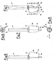
- variable nozzle for a gas turbine fixed to a shaft, said variable nozzle comprising a pressurized first surface and a depressurized second surface opposite to the first surface, wherein the variable nozzle comprises a series of a substantially "C" - shaped sections, each having a first rounded end and a second rounded end, each section of the series of sections also having the concavity facing upwards with respect to a base characterised by arranging each section of the series of sections continuously one after another and arranging the first end of each section in the series of sections in the direction of an axis of the shaft along an at least second degree curved line, which lies on a surface having an axis orthogonal to the axis of the shaft and also tilted with respect to the base by an angle.
- the first and second surfaces of the variable nozzle are also referred to herein respectively as upper and lower surfaces.
- variable nozzle 10 for a gas turbine fixed to a shaft 11 and capable of being rotated around its axis by means of activating means not shown in the figures.
- the shaped variable nozzle 10 is suitable for minimizing pressure drops and consequently increasing the efficiency of the gas turbine.
- Said variable nozzle 10 has a series of sections, preferably variable, substantially "C"-shaped, all facing the same direction, and preferably with the concavity facing upwards with respect to a base 90.
- Each section of the series of sections represents a section of the variable nozzle 10 according to a surface having an axis parallel to the axis of the shaft 11.
- Each section of the series of sections has a first rounded end 20 and a second rounded end 21.
- the first end 20 of each section of the series of sections is situated along the axis of the shaft 11 according to an at least second degree curved line 60.
- the series of sections is positioned along the axis of the shaft 11 and respectively defines two surfaces, an upper pressurized surface 12 and an opposite lower surface 14, which is depressurized, respectively, both touched by the hot combusted gases.
- the pressure of the flow F of hot gas is exerted on the upper surface 12, whereas the opposite lower surface 14, is in depression.
- the upper surface 12 is saddle-shaped and its saddle point corresponds to the intermediate section of the variable nozzle 10.
- the upper surface 12, in a parallel direction to the axis of the shaft 11, is therefore convex, whereas in an orthogonal direction to said axis, it is concave, all the sections being substantially "C"-shaped.
- the variable nozzle 10 has a first end portion 17, a second central portion 18, and a third hub portion 19.
- the first portion 17 and the third portion respectively comprise an end section 30 and a hub section 50, which have minimum aerodynamic pressure drops which consequently improve the aerodynamic efficiency of the variable nozzle 10.
- the second central portion 18, on the other hand, comprises the intermediate section 40.
- variable nozzle 10 is shaped so as to increase the aerodynamic charge thereon.
- Said curved line 60 lies on a surface 70 having an axis orthogonal to the axis of the shaft 11 and also tilted with respect to the base 90 by an angle 80 different from 0° and lower than 90°.
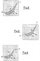
- Said curved line 60 is an at least second degree line and comprises a parabolic line or a hyperbolic line or a combination of these.
- said curved line 60 is preferably a parabolic line.
- variable nozzle 10 is therefore an arched nozzle, preferably parabolically arched.
- said curved line 60 is preferably a hyperbolic line.
- said curved line 60 is preferably a third degree line.
- Said curved line 60 moreover, preferably has a maximum or minimum point.
- variable nozzle for a gas turbine achieves the objectives specified above.
- variable nozzle for a gas turbine of the present invention Numerous modifications and variants can be applied to the variable nozzle for a gas turbine of the present invention, thus conceived, all included within the same inventive concept.
Landscapes
- Engineering & Computer Science (AREA)
- Mechanical Engineering (AREA)
- General Engineering & Computer Science (AREA)
- Physics & Mathematics (AREA)
- Fluid Mechanics (AREA)
- Control Of Turbines (AREA)
- Turbine Rotor Nozzle Sealing (AREA)
Applications Claiming Priority (2)
| Application Number | Priority Date | Filing Date | Title |
|---|---|---|---|
| IT002388A ITMI20032388A1 (it) | 2003-12-05 | 2003-12-05 | Ugello variabile per una turbina a gas. |
| PCT/EP2004/013657 WO2005054633A1 (en) | 2003-12-05 | 2004-11-30 | Variable nozzle for a gas turbine |
Publications (2)
| Publication Number | Publication Date |
|---|---|
| EP1721065A1 EP1721065A1 (en) | 2006-11-15 |
| EP1721065B1 true EP1721065B1 (en) | 2016-04-13 |
Family
ID=34640366
Family Applications (1)
| Application Number | Title | Priority Date | Filing Date |
|---|---|---|---|
| EP04803418.5A Active EP1721065B1 (en) | 2003-12-05 | 2004-11-30 | Variable nozzle for a gas turbine |
Country Status (9)
| Country | Link |
|---|---|
| US (1) | US7354242B2 (zh) |
| EP (1) | EP1721065B1 (zh) |
| JP (1) | JP2007513283A (zh) |
| KR (1) | KR20060123331A (zh) |
| CN (1) | CN100557201C (zh) |
| CA (1) | CA2548535C (zh) |
| IT (1) | ITMI20032388A1 (zh) |
| NO (1) | NO20063096L (zh) |
| WO (1) | WO2005054633A1 (zh) |
Families Citing this family (6)
| Publication number | Priority date | Publication date | Assignee | Title |
|---|---|---|---|---|
| DE102005060699A1 (de) | 2005-12-19 | 2007-06-21 | Rolls-Royce Deutschland Ltd & Co Kg | Strömungsarbeitsmaschine mit Verstellstator |
| DE102007020476A1 (de) * | 2007-04-27 | 2008-11-06 | Rolls-Royce Deutschland Ltd & Co Kg | Vorderkantenverlauf für Turbomaschinenkomponenten |
| CN101915130B (zh) * | 2010-06-25 | 2013-04-03 | 北京理工大学 | 可变几何涡轮增压器喷嘴环三维叶片及其设计方法 |
| EP2476862B1 (en) | 2011-01-13 | 2013-11-20 | Alstom Technology Ltd | Vane for an axial flow turbomachine and corresponding turbomachine |
| US9879540B2 (en) | 2013-03-12 | 2018-01-30 | Pratt & Whitney Canada Corp. | Compressor stator with contoured endwall |
| CN103711528B (zh) * | 2013-10-22 | 2015-04-08 | 萍乡市慧成精密机电有限公司 | 混流涡轮增压器可变喷嘴环 |
Family Cites Families (6)
| Publication number | Priority date | Publication date | Assignee | Title |
|---|---|---|---|---|
| FR2055780A1 (zh) * | 1969-08-14 | 1971-04-30 | Bennes Marrel | |
| SE410331B (sv) * | 1976-09-24 | 1979-10-08 | Kronogard Sven Olof | Statorkonstruktion avsedd att placeras nedstroms en separat arbetsturbinrotor |
| US4995786A (en) * | 1989-09-28 | 1991-02-26 | United Technologies Corporation | Dual variable camber compressor stator vane |
| US5088892A (en) * | 1990-02-07 | 1992-02-18 | United Technologies Corporation | Bowed airfoil for the compression section of a rotary machine |
| DE19950227A1 (de) * | 1999-10-19 | 2000-11-16 | Voith Hydro Gmbh & Co Kg | Hydraulische Strömungsmaschine |
| FR2814205B1 (fr) * | 2000-09-18 | 2003-02-28 | Snecma Moteurs | Turbomachine a veine d'ecoulement ameliore |
-
2003
- 2003-12-05 IT IT002388A patent/ITMI20032388A1/it unknown
-
2004
- 2004-11-30 JP JP2006541885A patent/JP2007513283A/ja active Pending
- 2004-11-30 KR KR1020067011735A patent/KR20060123331A/ko not_active Application Discontinuation
- 2004-11-30 EP EP04803418.5A patent/EP1721065B1/en active Active
- 2004-11-30 CA CA2548535A patent/CA2548535C/en not_active Expired - Fee Related
- 2004-11-30 US US10/596,191 patent/US7354242B2/en active Active
- 2004-11-30 WO PCT/EP2004/013657 patent/WO2005054633A1/en active Application Filing
- 2004-11-30 CN CNB2004800359964A patent/CN100557201C/zh active Active
-
2006
- 2006-07-04 NO NO20063096A patent/NO20063096L/no not_active Application Discontinuation
Also Published As
| Publication number | Publication date |
|---|---|
| ITMI20032388A1 (it) | 2005-06-06 |
| CA2548535A1 (en) | 2005-06-16 |
| US20070086886A1 (en) | 2007-04-19 |
| EP1721065A1 (en) | 2006-11-15 |
| JP2007513283A (ja) | 2007-05-24 |
| CN1890455A (zh) | 2007-01-03 |
| US7354242B2 (en) | 2008-04-08 |
| NO20063096L (no) | 2006-09-04 |
| CA2548535C (en) | 2012-10-09 |
| KR20060123331A (ko) | 2006-12-01 |
| WO2005054633A1 (en) | 2005-06-16 |
| CN100557201C (zh) | 2009-11-04 |
Similar Documents
| Publication | Publication Date | Title |
|---|---|---|
| US8585360B2 (en) | Turbine vane nominal airfoil profile | |
| CN101349167B (zh) | 轴流式涡轮机 | |
| EP2066873B1 (en) | Turbomachine with an adjustable vane system | |
| CN100504035C (zh) | 混流式涡轮机和混流式涡轮机转子叶片 | |
| US9765753B2 (en) | Impulse turbine for use in bi-directional flows | |
| EP2820279B1 (en) | Turbomachine blade | |
| EP1259711B1 (en) | Aerofoil for an axial flow turbomachine | |
| EP2476862B1 (en) | Vane for an axial flow turbomachine and corresponding turbomachine | |
| US7448847B2 (en) | Turbine with adjustable vanes | |
| JP2015537150A (ja) | 曲線輪郭のステータシュラウド | |
| EP2586979B1 (en) | Turbomachine blade with tip flare | |
| JP2002310100A (ja) | 案内羽根、該羽根を製造する方法およびステータ | |
| GB2028438A (en) | High-load compressor with variavble guide vanes | |
| EP2118468A2 (en) | Turbocharger vane | |
| GB2427004A (en) | Turbine nozzle with purge cavity blend | |
| EP1721065B1 (en) | Variable nozzle for a gas turbine | |
| EP3231996B1 (en) | A blade for an axial flow machine | |
| US20020146316A1 (en) | Methods and apparatus for adjusting gas turbine engine variable vanes | |
| US20110158792A1 (en) | Engine and vane actuation system for turbine engine | |
| EP3569827B1 (en) | Variable diffuser having a respective penny for each vane | |
| EP3567222B1 (en) | Variable diffuser having a respective penny for each vane | |
| KR20230000393A (ko) | 냉각홀을 구비하는 터빈 블레이드 및 이를 포함하는 터빈 | |
| JP2024114373A (ja) | ラジアルタービンインペラ |
Legal Events
| Date | Code | Title | Description |
|---|---|---|---|
| PUAI | Public reference made under article 153(3) epc to a published international application that has entered the european phase |
Free format text: ORIGINAL CODE: 0009012 |
|
| 17P | Request for examination filed |
Effective date: 20060705 |
|
| AK | Designated contracting states |
Kind code of ref document: A1 Designated state(s): CH DE FR GB LI NL |
|
| DAX | Request for extension of the european patent (deleted) | ||
| RBV | Designated contracting states (corrected) |
Designated state(s): CH DE FR GB LI NL |
|
| 17Q | First examination report despatched |
Effective date: 20080218 |
|
| GRAP | Despatch of communication of intention to grant a patent |
Free format text: ORIGINAL CODE: EPIDOSNIGR1 |
|
| INTG | Intention to grant announced |
Effective date: 20151119 |
|
| GRAS | Grant fee paid |
Free format text: ORIGINAL CODE: EPIDOSNIGR3 |
|
| GRAA | (expected) grant |
Free format text: ORIGINAL CODE: 0009210 |
|
| AK | Designated contracting states |
Kind code of ref document: B1 Designated state(s): CH DE FR GB LI NL |
|
| REG | Reference to a national code |
Ref country code: GB Ref legal event code: FG4D |
|
| REG | Reference to a national code |
Ref country code: CH Ref legal event code: EP |
|
| REG | Reference to a national code |
Ref country code: DE Ref legal event code: R096 Ref document number: 602004049073 Country of ref document: DE |
|
| REG | Reference to a national code |
Ref country code: NL Ref legal event code: MP Effective date: 20160413 |
|
| PG25 | Lapsed in a contracting state [announced via postgrant information from national office to epo] |
Ref country code: NL Free format text: LAPSE BECAUSE OF FAILURE TO SUBMIT A TRANSLATION OF THE DESCRIPTION OR TO PAY THE FEE WITHIN THE PRESCRIBED TIME-LIMIT Effective date: 20160413 |
|
| REG | Reference to a national code |
Ref country code: FR Ref legal event code: PLFP Year of fee payment: 13 |
|
| REG | Reference to a national code |
Ref country code: DE Ref legal event code: R097 Ref document number: 602004049073 Country of ref document: DE |
|
| PLBE | No opposition filed within time limit |
Free format text: ORIGINAL CODE: 0009261 |
|
| STAA | Information on the status of an ep patent application or granted ep patent |
Free format text: STATUS: NO OPPOSITION FILED WITHIN TIME LIMIT |
|
| 26N | No opposition filed |
Effective date: 20170116 |
|
| REG | Reference to a national code |
Ref country code: FR Ref legal event code: PLFP Year of fee payment: 14 |
|
| REG | Reference to a national code |
Ref country code: FR Ref legal event code: PLFP Year of fee payment: 15 |
|
| REG | Reference to a national code |
Ref country code: GB Ref legal event code: 732E Free format text: REGISTERED BETWEEN 20220414 AND 20220420 |
|
| REG | Reference to a national code |
Ref country code: CH Ref legal event code: PK Free format text: BERICHTIGUNGEN |
|
| REG | Reference to a national code |
Ref country code: GB Ref legal event code: 732E Free format text: REGISTERED BETWEEN 20220728 AND 20220803 |
|
| PGFP | Annual fee paid to national office [announced via postgrant information from national office to epo] |
Ref country code: GB Payment date: 20231019 Year of fee payment: 20 |
|
| PGFP | Annual fee paid to national office [announced via postgrant information from national office to epo] |
Ref country code: FR Payment date: 20231019 Year of fee payment: 20 Ref country code: DE Payment date: 20231019 Year of fee payment: 20 Ref country code: CH Payment date: 20231201 Year of fee payment: 20 |
|
| REG | Reference to a national code |
Ref country code: DE Ref legal event code: R081 Ref document number: 602004049073 Country of ref document: DE Owner name: NUOVO PIGNONE TECNOLOGIE - S.R.L., IT Free format text: FORMER OWNER: NUOVO PIGNONE HOLDING S.P.A., FIRENZE, IT Ref country code: DE Ref legal event code: R081 Ref document number: 602004049073 Country of ref document: DE Owner name: NUOVO PIGNONE TECNOLOGIE SRL, IT Free format text: FORMER OWNER: NUOVO PIGNONE HOLDING S.P.A., FIRENZE, IT |
|
| REG | Reference to a national code |
Ref country code: DE Ref legal event code: R081 Ref document number: 602004049073 Country of ref document: DE Owner name: NUOVO PIGNONE TECNOLOGIE - S.R.L., IT Free format text: FORMER OWNER: NUOVO PIGNONE TECNOLOGIE SRL, FLORENZ, IT |