EP1720491B1 - Universal interference cleat for vertebral prosthesis - Google Patents
Universal interference cleat for vertebral prosthesis Download PDFInfo
- Publication number
- EP1720491B1 EP1720491B1 EP05705632.7A EP05705632A EP1720491B1 EP 1720491 B1 EP1720491 B1 EP 1720491B1 EP 05705632 A EP05705632 A EP 05705632A EP 1720491 B1 EP1720491 B1 EP 1720491B1
- Authority
- EP
- European Patent Office
- Prior art keywords
- cleat
- vertebral
- end wall
- tubular body
- vertebral implant
- Prior art date
- Legal status (The legal status is an assumption and is not a legal conclusion. Google has not performed a legal analysis and makes no representation as to the accuracy of the status listed.)
- Not-in-force
Links
Images


Classifications
-
- A—HUMAN NECESSITIES
- A61—MEDICAL OR VETERINARY SCIENCE; HYGIENE
- A61F—FILTERS IMPLANTABLE INTO BLOOD VESSELS; PROSTHESES; DEVICES PROVIDING PATENCY TO, OR PREVENTING COLLAPSING OF, TUBULAR STRUCTURES OF THE BODY, e.g. STENTS; ORTHOPAEDIC, NURSING OR CONTRACEPTIVE DEVICES; FOMENTATION; TREATMENT OR PROTECTION OF EYES OR EARS; BANDAGES, DRESSINGS OR ABSORBENT PADS; FIRST-AID KITS
- A61F2/00—Filters implantable into blood vessels; Prostheses, i.e. artificial substitutes or replacements for parts of the body; Appliances for connecting them with the body; Devices providing patency to, or preventing collapsing of, tubular structures of the body, e.g. stents
- A61F2/02—Prostheses implantable into the body
- A61F2/30—Joints
- A61F2/44—Joints for the spine, e.g. vertebrae, spinal discs
-
- A—HUMAN NECESSITIES
- A61—MEDICAL OR VETERINARY SCIENCE; HYGIENE
- A61F—FILTERS IMPLANTABLE INTO BLOOD VESSELS; PROSTHESES; DEVICES PROVIDING PATENCY TO, OR PREVENTING COLLAPSING OF, TUBULAR STRUCTURES OF THE BODY, e.g. STENTS; ORTHOPAEDIC, NURSING OR CONTRACEPTIVE DEVICES; FOMENTATION; TREATMENT OR PROTECTION OF EYES OR EARS; BANDAGES, DRESSINGS OR ABSORBENT PADS; FIRST-AID KITS
- A61F2/00—Filters implantable into blood vessels; Prostheses, i.e. artificial substitutes or replacements for parts of the body; Appliances for connecting them with the body; Devices providing patency to, or preventing collapsing of, tubular structures of the body, e.g. stents
- A61F2/02—Prostheses implantable into the body
- A61F2/28—Bones
-
- A—HUMAN NECESSITIES
- A61—MEDICAL OR VETERINARY SCIENCE; HYGIENE
- A61F—FILTERS IMPLANTABLE INTO BLOOD VESSELS; PROSTHESES; DEVICES PROVIDING PATENCY TO, OR PREVENTING COLLAPSING OF, TUBULAR STRUCTURES OF THE BODY, e.g. STENTS; ORTHOPAEDIC, NURSING OR CONTRACEPTIVE DEVICES; FOMENTATION; TREATMENT OR PROTECTION OF EYES OR EARS; BANDAGES, DRESSINGS OR ABSORBENT PADS; FIRST-AID KITS
- A61F2/00—Filters implantable into blood vessels; Prostheses, i.e. artificial substitutes or replacements for parts of the body; Appliances for connecting them with the body; Devices providing patency to, or preventing collapsing of, tubular structures of the body, e.g. stents
- A61F2/02—Prostheses implantable into the body
- A61F2/30—Joints
- A61F2/30721—Accessories
- A61F2/30728—Collars; Bone edge protectors
-
- A—HUMAN NECESSITIES
- A61—MEDICAL OR VETERINARY SCIENCE; HYGIENE
- A61F—FILTERS IMPLANTABLE INTO BLOOD VESSELS; PROSTHESES; DEVICES PROVIDING PATENCY TO, OR PREVENTING COLLAPSING OF, TUBULAR STRUCTURES OF THE BODY, e.g. STENTS; ORTHOPAEDIC, NURSING OR CONTRACEPTIVE DEVICES; FOMENTATION; TREATMENT OR PROTECTION OF EYES OR EARS; BANDAGES, DRESSINGS OR ABSORBENT PADS; FIRST-AID KITS
- A61F2/00—Filters implantable into blood vessels; Prostheses, i.e. artificial substitutes or replacements for parts of the body; Appliances for connecting them with the body; Devices providing patency to, or preventing collapsing of, tubular structures of the body, e.g. stents
- A61F2/02—Prostheses implantable into the body
- A61F2/30—Joints
- A61F2/46—Special tools or methods for implanting or extracting artificial joints, accessories, bone grafts or substitutes, or particular adaptations therefor
- A61F2/4603—Special tools or methods for implanting or extracting artificial joints, accessories, bone grafts or substitutes, or particular adaptations therefor for insertion or extraction of endoprosthetic joints or of accessories thereof
- A61F2/4611—Special tools or methods for implanting or extracting artificial joints, accessories, bone grafts or substitutes, or particular adaptations therefor for insertion or extraction of endoprosthetic joints or of accessories thereof of spinal prostheses
-
- A—HUMAN NECESSITIES
- A61—MEDICAL OR VETERINARY SCIENCE; HYGIENE
- A61F—FILTERS IMPLANTABLE INTO BLOOD VESSELS; PROSTHESES; DEVICES PROVIDING PATENCY TO, OR PREVENTING COLLAPSING OF, TUBULAR STRUCTURES OF THE BODY, e.g. STENTS; ORTHOPAEDIC, NURSING OR CONTRACEPTIVE DEVICES; FOMENTATION; TREATMENT OR PROTECTION OF EYES OR EARS; BANDAGES, DRESSINGS OR ABSORBENT PADS; FIRST-AID KITS
- A61F2/00—Filters implantable into blood vessels; Prostheses, i.e. artificial substitutes or replacements for parts of the body; Appliances for connecting them with the body; Devices providing patency to, or preventing collapsing of, tubular structures of the body, e.g. stents
- A61F2/02—Prostheses implantable into the body
- A61F2/28—Bones
- A61F2002/2835—Bone graft implants for filling a bony defect or an endoprosthesis cavity, e.g. by synthetic material or biological material
-
- A—HUMAN NECESSITIES
- A61—MEDICAL OR VETERINARY SCIENCE; HYGIENE
- A61F—FILTERS IMPLANTABLE INTO BLOOD VESSELS; PROSTHESES; DEVICES PROVIDING PATENCY TO, OR PREVENTING COLLAPSING OF, TUBULAR STRUCTURES OF THE BODY, e.g. STENTS; ORTHOPAEDIC, NURSING OR CONTRACEPTIVE DEVICES; FOMENTATION; TREATMENT OR PROTECTION OF EYES OR EARS; BANDAGES, DRESSINGS OR ABSORBENT PADS; FIRST-AID KITS
- A61F2/00—Filters implantable into blood vessels; Prostheses, i.e. artificial substitutes or replacements for parts of the body; Appliances for connecting them with the body; Devices providing patency to, or preventing collapsing of, tubular structures of the body, e.g. stents
- A61F2/02—Prostheses implantable into the body
- A61F2/30—Joints
- A61F2002/30001—Additional features of subject-matter classified in A61F2/28, A61F2/30 and subgroups thereof
- A61F2002/30108—Shapes
- A61F2002/30199—Three-dimensional shapes
- A61F2002/302—Three-dimensional shapes toroidal, e.g. rings
-
- A—HUMAN NECESSITIES
- A61—MEDICAL OR VETERINARY SCIENCE; HYGIENE
- A61F—FILTERS IMPLANTABLE INTO BLOOD VESSELS; PROSTHESES; DEVICES PROVIDING PATENCY TO, OR PREVENTING COLLAPSING OF, TUBULAR STRUCTURES OF THE BODY, e.g. STENTS; ORTHOPAEDIC, NURSING OR CONTRACEPTIVE DEVICES; FOMENTATION; TREATMENT OR PROTECTION OF EYES OR EARS; BANDAGES, DRESSINGS OR ABSORBENT PADS; FIRST-AID KITS
- A61F2/00—Filters implantable into blood vessels; Prostheses, i.e. artificial substitutes or replacements for parts of the body; Appliances for connecting them with the body; Devices providing patency to, or preventing collapsing of, tubular structures of the body, e.g. stents
- A61F2/02—Prostheses implantable into the body
- A61F2/30—Joints
- A61F2002/30001—Additional features of subject-matter classified in A61F2/28, A61F2/30 and subgroups thereof
- A61F2002/30108—Shapes
- A61F2002/30199—Three-dimensional shapes
- A61F2002/30224—Three-dimensional shapes cylindrical
- A61F2002/30235—Three-dimensional shapes cylindrical tubular, e.g. sleeves
-
- A—HUMAN NECESSITIES
- A61—MEDICAL OR VETERINARY SCIENCE; HYGIENE
- A61F—FILTERS IMPLANTABLE INTO BLOOD VESSELS; PROSTHESES; DEVICES PROVIDING PATENCY TO, OR PREVENTING COLLAPSING OF, TUBULAR STRUCTURES OF THE BODY, e.g. STENTS; ORTHOPAEDIC, NURSING OR CONTRACEPTIVE DEVICES; FOMENTATION; TREATMENT OR PROTECTION OF EYES OR EARS; BANDAGES, DRESSINGS OR ABSORBENT PADS; FIRST-AID KITS
- A61F2/00—Filters implantable into blood vessels; Prostheses, i.e. artificial substitutes or replacements for parts of the body; Appliances for connecting them with the body; Devices providing patency to, or preventing collapsing of, tubular structures of the body, e.g. stents
- A61F2/02—Prostheses implantable into the body
- A61F2/30—Joints
- A61F2002/30001—Additional features of subject-matter classified in A61F2/28, A61F2/30 and subgroups thereof
- A61F2002/30316—The prosthesis having different structural features at different locations within the same prosthesis; Connections between prosthetic parts; Special structural features of bone or joint prostheses not otherwise provided for
- A61F2002/30329—Connections or couplings between prosthetic parts, e.g. between modular parts; Connecting elements
- A61F2002/30331—Connections or couplings between prosthetic parts, e.g. between modular parts; Connecting elements made by longitudinally pushing a protrusion into a complementarily-shaped recess, e.g. held by friction fit
- A61F2002/30332—Conically- or frustoconically-shaped protrusion and recess
-
- A—HUMAN NECESSITIES
- A61—MEDICAL OR VETERINARY SCIENCE; HYGIENE
- A61F—FILTERS IMPLANTABLE INTO BLOOD VESSELS; PROSTHESES; DEVICES PROVIDING PATENCY TO, OR PREVENTING COLLAPSING OF, TUBULAR STRUCTURES OF THE BODY, e.g. STENTS; ORTHOPAEDIC, NURSING OR CONTRACEPTIVE DEVICES; FOMENTATION; TREATMENT OR PROTECTION OF EYES OR EARS; BANDAGES, DRESSINGS OR ABSORBENT PADS; FIRST-AID KITS
- A61F2/00—Filters implantable into blood vessels; Prostheses, i.e. artificial substitutes or replacements for parts of the body; Appliances for connecting them with the body; Devices providing patency to, or preventing collapsing of, tubular structures of the body, e.g. stents
- A61F2/02—Prostheses implantable into the body
- A61F2/30—Joints
- A61F2002/30001—Additional features of subject-matter classified in A61F2/28, A61F2/30 and subgroups thereof
- A61F2002/30316—The prosthesis having different structural features at different locations within the same prosthesis; Connections between prosthetic parts; Special structural features of bone or joint prostheses not otherwise provided for
- A61F2002/30329—Connections or couplings between prosthetic parts, e.g. between modular parts; Connecting elements
- A61F2002/30476—Connections or couplings between prosthetic parts, e.g. between modular parts; Connecting elements locked by an additional locking mechanism
- A61F2002/30481—Connections or couplings between prosthetic parts, e.g. between modular parts; Connecting elements locked by an additional locking mechanism using a locking clip
-
- A—HUMAN NECESSITIES
- A61—MEDICAL OR VETERINARY SCIENCE; HYGIENE
- A61F—FILTERS IMPLANTABLE INTO BLOOD VESSELS; PROSTHESES; DEVICES PROVIDING PATENCY TO, OR PREVENTING COLLAPSING OF, TUBULAR STRUCTURES OF THE BODY, e.g. STENTS; ORTHOPAEDIC, NURSING OR CONTRACEPTIVE DEVICES; FOMENTATION; TREATMENT OR PROTECTION OF EYES OR EARS; BANDAGES, DRESSINGS OR ABSORBENT PADS; FIRST-AID KITS
- A61F2/00—Filters implantable into blood vessels; Prostheses, i.e. artificial substitutes or replacements for parts of the body; Appliances for connecting them with the body; Devices providing patency to, or preventing collapsing of, tubular structures of the body, e.g. stents
- A61F2/02—Prostheses implantable into the body
- A61F2/30—Joints
- A61F2002/30001—Additional features of subject-matter classified in A61F2/28, A61F2/30 and subgroups thereof
- A61F2002/30316—The prosthesis having different structural features at different locations within the same prosthesis; Connections between prosthetic parts; Special structural features of bone or joint prostheses not otherwise provided for
- A61F2002/30329—Connections or couplings between prosthetic parts, e.g. between modular parts; Connecting elements
- A61F2002/30476—Connections or couplings between prosthetic parts, e.g. between modular parts; Connecting elements locked by an additional locking mechanism
- A61F2002/30492—Connections or couplings between prosthetic parts, e.g. between modular parts; Connecting elements locked by an additional locking mechanism using a locking pin
-
- A—HUMAN NECESSITIES
- A61—MEDICAL OR VETERINARY SCIENCE; HYGIENE
- A61F—FILTERS IMPLANTABLE INTO BLOOD VESSELS; PROSTHESES; DEVICES PROVIDING PATENCY TO, OR PREVENTING COLLAPSING OF, TUBULAR STRUCTURES OF THE BODY, e.g. STENTS; ORTHOPAEDIC, NURSING OR CONTRACEPTIVE DEVICES; FOMENTATION; TREATMENT OR PROTECTION OF EYES OR EARS; BANDAGES, DRESSINGS OR ABSORBENT PADS; FIRST-AID KITS
- A61F2/00—Filters implantable into blood vessels; Prostheses, i.e. artificial substitutes or replacements for parts of the body; Appliances for connecting them with the body; Devices providing patency to, or preventing collapsing of, tubular structures of the body, e.g. stents
- A61F2/02—Prostheses implantable into the body
- A61F2/30—Joints
- A61F2002/30001—Additional features of subject-matter classified in A61F2/28, A61F2/30 and subgroups thereof
- A61F2002/30316—The prosthesis having different structural features at different locations within the same prosthesis; Connections between prosthetic parts; Special structural features of bone or joint prostheses not otherwise provided for
- A61F2002/30329—Connections or couplings between prosthetic parts, e.g. between modular parts; Connecting elements
- A61F2002/30476—Connections or couplings between prosthetic parts, e.g. between modular parts; Connecting elements locked by an additional locking mechanism
- A61F2002/30507—Connections or couplings between prosthetic parts, e.g. between modular parts; Connecting elements locked by an additional locking mechanism using a threaded locking member, e.g. a locking screw or a set screw
-
- A—HUMAN NECESSITIES
- A61—MEDICAL OR VETERINARY SCIENCE; HYGIENE
- A61F—FILTERS IMPLANTABLE INTO BLOOD VESSELS; PROSTHESES; DEVICES PROVIDING PATENCY TO, OR PREVENTING COLLAPSING OF, TUBULAR STRUCTURES OF THE BODY, e.g. STENTS; ORTHOPAEDIC, NURSING OR CONTRACEPTIVE DEVICES; FOMENTATION; TREATMENT OR PROTECTION OF EYES OR EARS; BANDAGES, DRESSINGS OR ABSORBENT PADS; FIRST-AID KITS
- A61F2/00—Filters implantable into blood vessels; Prostheses, i.e. artificial substitutes or replacements for parts of the body; Appliances for connecting them with the body; Devices providing patency to, or preventing collapsing of, tubular structures of the body, e.g. stents
- A61F2/02—Prostheses implantable into the body
- A61F2/30—Joints
- A61F2002/30001—Additional features of subject-matter classified in A61F2/28, A61F2/30 and subgroups thereof
- A61F2002/30316—The prosthesis having different structural features at different locations within the same prosthesis; Connections between prosthetic parts; Special structural features of bone or joint prostheses not otherwise provided for
- A61F2002/30535—Special structural features of bone or joint prostheses not otherwise provided for
- A61F2002/30601—Special structural features of bone or joint prostheses not otherwise provided for telescopic
-
- A—HUMAN NECESSITIES
- A61—MEDICAL OR VETERINARY SCIENCE; HYGIENE
- A61F—FILTERS IMPLANTABLE INTO BLOOD VESSELS; PROSTHESES; DEVICES PROVIDING PATENCY TO, OR PREVENTING COLLAPSING OF, TUBULAR STRUCTURES OF THE BODY, e.g. STENTS; ORTHOPAEDIC, NURSING OR CONTRACEPTIVE DEVICES; FOMENTATION; TREATMENT OR PROTECTION OF EYES OR EARS; BANDAGES, DRESSINGS OR ABSORBENT PADS; FIRST-AID KITS
- A61F2/00—Filters implantable into blood vessels; Prostheses, i.e. artificial substitutes or replacements for parts of the body; Appliances for connecting them with the body; Devices providing patency to, or preventing collapsing of, tubular structures of the body, e.g. stents
- A61F2/02—Prostheses implantable into the body
- A61F2/30—Joints
- A61F2002/30001—Additional features of subject-matter classified in A61F2/28, A61F2/30 and subgroups thereof
- A61F2002/30316—The prosthesis having different structural features at different locations within the same prosthesis; Connections between prosthetic parts; Special structural features of bone or joint prostheses not otherwise provided for
- A61F2002/30535—Special structural features of bone or joint prostheses not otherwise provided for
- A61F2002/30604—Special structural features of bone or joint prostheses not otherwise provided for modular
- A61F2002/30616—Sets comprising a plurality of prosthetic parts of different sizes or orientations
-
- A—HUMAN NECESSITIES
- A61—MEDICAL OR VETERINARY SCIENCE; HYGIENE
- A61F—FILTERS IMPLANTABLE INTO BLOOD VESSELS; PROSTHESES; DEVICES PROVIDING PATENCY TO, OR PREVENTING COLLAPSING OF, TUBULAR STRUCTURES OF THE BODY, e.g. STENTS; ORTHOPAEDIC, NURSING OR CONTRACEPTIVE DEVICES; FOMENTATION; TREATMENT OR PROTECTION OF EYES OR EARS; BANDAGES, DRESSINGS OR ABSORBENT PADS; FIRST-AID KITS
- A61F2/00—Filters implantable into blood vessels; Prostheses, i.e. artificial substitutes or replacements for parts of the body; Appliances for connecting them with the body; Devices providing patency to, or preventing collapsing of, tubular structures of the body, e.g. stents
- A61F2/02—Prostheses implantable into the body
- A61F2/30—Joints
- A61F2/30767—Special external or bone-contacting surface, e.g. coating for improving bone ingrowth
- A61F2/30771—Special external or bone-contacting surface, e.g. coating for improving bone ingrowth applied in original prostheses, e.g. holes or grooves
- A61F2002/30772—Apertures or holes, e.g. of circular cross section
- A61F2002/30784—Plurality of holes
-
- A—HUMAN NECESSITIES
- A61—MEDICAL OR VETERINARY SCIENCE; HYGIENE
- A61F—FILTERS IMPLANTABLE INTO BLOOD VESSELS; PROSTHESES; DEVICES PROVIDING PATENCY TO, OR PREVENTING COLLAPSING OF, TUBULAR STRUCTURES OF THE BODY, e.g. STENTS; ORTHOPAEDIC, NURSING OR CONTRACEPTIVE DEVICES; FOMENTATION; TREATMENT OR PROTECTION OF EYES OR EARS; BANDAGES, DRESSINGS OR ABSORBENT PADS; FIRST-AID KITS
- A61F2/00—Filters implantable into blood vessels; Prostheses, i.e. artificial substitutes or replacements for parts of the body; Appliances for connecting them with the body; Devices providing patency to, or preventing collapsing of, tubular structures of the body, e.g. stents
- A61F2/02—Prostheses implantable into the body
- A61F2/30—Joints
- A61F2/30767—Special external or bone-contacting surface, e.g. coating for improving bone ingrowth
- A61F2/30771—Special external or bone-contacting surface, e.g. coating for improving bone ingrowth applied in original prostheses, e.g. holes or grooves
- A61F2002/30841—Sharp anchoring protrusions for impaction into the bone, e.g. sharp pins, spikes
-
- A—HUMAN NECESSITIES
- A61—MEDICAL OR VETERINARY SCIENCE; HYGIENE
- A61F—FILTERS IMPLANTABLE INTO BLOOD VESSELS; PROSTHESES; DEVICES PROVIDING PATENCY TO, OR PREVENTING COLLAPSING OF, TUBULAR STRUCTURES OF THE BODY, e.g. STENTS; ORTHOPAEDIC, NURSING OR CONTRACEPTIVE DEVICES; FOMENTATION; TREATMENT OR PROTECTION OF EYES OR EARS; BANDAGES, DRESSINGS OR ABSORBENT PADS; FIRST-AID KITS
- A61F2220/00—Fixations or connections for prostheses classified in groups A61F2/00 - A61F2/26 or A61F2/82 or A61F9/00 or A61F11/00 or subgroups thereof
- A61F2220/0025—Connections or couplings between prosthetic parts, e.g. between modular parts; Connecting elements
- A61F2220/0033—Connections or couplings between prosthetic parts, e.g. between modular parts; Connecting elements made by longitudinally pushing a protrusion into a complementary-shaped recess, e.g. held by friction fit
-
- A—HUMAN NECESSITIES
- A61—MEDICAL OR VETERINARY SCIENCE; HYGIENE
- A61F—FILTERS IMPLANTABLE INTO BLOOD VESSELS; PROSTHESES; DEVICES PROVIDING PATENCY TO, OR PREVENTING COLLAPSING OF, TUBULAR STRUCTURES OF THE BODY, e.g. STENTS; ORTHOPAEDIC, NURSING OR CONTRACEPTIVE DEVICES; FOMENTATION; TREATMENT OR PROTECTION OF EYES OR EARS; BANDAGES, DRESSINGS OR ABSORBENT PADS; FIRST-AID KITS
- A61F2230/00—Geometry of prostheses classified in groups A61F2/00 - A61F2/26 or A61F2/82 or A61F9/00 or A61F11/00 or subgroups thereof
- A61F2230/0063—Three-dimensional shapes
- A61F2230/0065—Three-dimensional shapes toroidal, e.g. ring-shaped, doughnut-shaped
-
- A—HUMAN NECESSITIES
- A61—MEDICAL OR VETERINARY SCIENCE; HYGIENE
- A61F—FILTERS IMPLANTABLE INTO BLOOD VESSELS; PROSTHESES; DEVICES PROVIDING PATENCY TO, OR PREVENTING COLLAPSING OF, TUBULAR STRUCTURES OF THE BODY, e.g. STENTS; ORTHOPAEDIC, NURSING OR CONTRACEPTIVE DEVICES; FOMENTATION; TREATMENT OR PROTECTION OF EYES OR EARS; BANDAGES, DRESSINGS OR ABSORBENT PADS; FIRST-AID KITS
- A61F2230/00—Geometry of prostheses classified in groups A61F2/00 - A61F2/26 or A61F2/82 or A61F9/00 or A61F11/00 or subgroups thereof
- A61F2230/0063—Three-dimensional shapes
- A61F2230/0069—Three-dimensional shapes cylindrical
-
- A—HUMAN NECESSITIES
- A61—MEDICAL OR VETERINARY SCIENCE; HYGIENE
- A61F—FILTERS IMPLANTABLE INTO BLOOD VESSELS; PROSTHESES; DEVICES PROVIDING PATENCY TO, OR PREVENTING COLLAPSING OF, TUBULAR STRUCTURES OF THE BODY, e.g. STENTS; ORTHOPAEDIC, NURSING OR CONTRACEPTIVE DEVICES; FOMENTATION; TREATMENT OR PROTECTION OF EYES OR EARS; BANDAGES, DRESSINGS OR ABSORBENT PADS; FIRST-AID KITS
- A61F2310/00—Prostheses classified in A61F2/28 or A61F2/30 - A61F2/44 being constructed from or coated with a particular material
- A61F2310/00005—The prosthesis being constructed from a particular material
- A61F2310/00011—Metals or alloys
- A61F2310/00017—Iron- or Fe-based alloys, e.g. stainless steel
-
- A—HUMAN NECESSITIES
- A61—MEDICAL OR VETERINARY SCIENCE; HYGIENE
- A61F—FILTERS IMPLANTABLE INTO BLOOD VESSELS; PROSTHESES; DEVICES PROVIDING PATENCY TO, OR PREVENTING COLLAPSING OF, TUBULAR STRUCTURES OF THE BODY, e.g. STENTS; ORTHOPAEDIC, NURSING OR CONTRACEPTIVE DEVICES; FOMENTATION; TREATMENT OR PROTECTION OF EYES OR EARS; BANDAGES, DRESSINGS OR ABSORBENT PADS; FIRST-AID KITS
- A61F2310/00—Prostheses classified in A61F2/28 or A61F2/30 - A61F2/44 being constructed from or coated with a particular material
- A61F2310/00005—The prosthesis being constructed from a particular material
- A61F2310/00011—Metals or alloys
- A61F2310/00029—Cobalt-based alloys, e.g. Co-Cr alloys or Vitallium
-
- A—HUMAN NECESSITIES
- A61—MEDICAL OR VETERINARY SCIENCE; HYGIENE
- A61F—FILTERS IMPLANTABLE INTO BLOOD VESSELS; PROSTHESES; DEVICES PROVIDING PATENCY TO, OR PREVENTING COLLAPSING OF, TUBULAR STRUCTURES OF THE BODY, e.g. STENTS; ORTHOPAEDIC, NURSING OR CONTRACEPTIVE DEVICES; FOMENTATION; TREATMENT OR PROTECTION OF EYES OR EARS; BANDAGES, DRESSINGS OR ABSORBENT PADS; FIRST-AID KITS
- A61F2310/00—Prostheses classified in A61F2/28 or A61F2/30 - A61F2/44 being constructed from or coated with a particular material
- A61F2310/00005—The prosthesis being constructed from a particular material
- A61F2310/00011—Metals or alloys
- A61F2310/00035—Other metals or alloys
- A61F2310/00131—Tantalum or Ta-based alloys
Definitions
- the present invention relates generally to an implant for replacement of one or more vertebral bodies and their adjacent discs, and more particularly, to a vertebral implant assembly having cleats for stabilizing the assembly.
- the implant of the initially - mentioned type is known for example, from US 2003/181980 A1 .
- a variety of spinal injuries and deformities can occur due to trauma, disease, or congenital effects. These injuries and diseases can, ultimately, result in the destruction of one or more vertebral bodies and lead to a vertebrectomy in which the one or more damaged vertebral bodies and their adjacent discs are excised. Reconstruction of the spine following the vertebrectomy can present a number of challenges for the surgeon.
- a vertebral implant between the remaining rostral and caudal vertebral bodies to ensure that the implant can resist axial, torsional, and shear loading without causing anterior displacement ("kick-out") or posterior retropulsion of the implant and any associated graft material.
- Existing vertebral implants which attempt to minimize these methods of failure can often result in other undesirable consequences such as instrumentation pull-out, graft or implant subsidence, graft dislodgment, or erosion of nearby vascular and soft tissue structures due to high profile design.
- a vertebral implant assembly that resists kick out and retropulsion without injuring proximate bone, vascular, or soft tissue structures and also without significantly lengthening or complicating the surgical procedure.
- the invention provides a vertebral implant according to claim 1 and a vertebral implant according to claim 11. Further embodiments of the invention are described in the dependent claims.
- WO 2004/089256 A discloses a vertebral implant similar to that according to claims 1 and 11, wherein, however, WO 2004/089256 A does not disclose that the body sized to fit between the two vertebral endplates is a tubular body, and does not disclose a combination of cleat assemblies with a biologic strut.
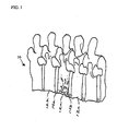
- the reference numeral 10 refers to a vertebral column with a damaged vertebra 12a extending between two intact vertebrae 12b and 12c.
- An intervertebral disc 14a extends between vertebrae 12a and 12b, and an intervertebral disc 14b extends between vertebrae 12a and 12c.
- the vertebra 12a is removed together with discs 14a and 14b creating a void between the two intact vertebra 12b and 12c. This procedure may be performed using an anterior, anterolateral, or other approach known to one skilled in the art.
- a vertebral implant assembly according to an embodiment of the present invention is then provided to fill the void between the two intact vertebrae 12b and 12c.
- the embodiment to be described is premised upon the removal of a single vertebra, it is understood that a different embodiment of the present invention may be inserted in an intervertebral disc space without the removal of a vertebrae when required by the surgical procedure.
- the present invention may be used in a vertebral column reconstruction following a vertebrectomy removing two or more diseased or damaged vertebrae and their adjacent discs.
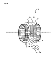
- a vertebral implant assembly according to an embodiment of the present invention is referred to, in general, by the reference numeral 20 and includes tubular body 22 connected between two cleat assemblies 24 and 26 in a manner to be described.
- the tubular body 22 defines a hollow bore 28 therethrough which is configured to receive bone osteogenetic material (not shown).
- the tubular body 22 can be provided with a plurality of openings 30 that permit bone and tissue ingrowth and vascularization.
- the body 22 may be provided in a variety of heights or may be trimmed to fit within the gap formed by the vertebral ablation to avoid damaging the weak bone of the adjacent intact vertebrae after implantation.
- a surgical mesh tube or "cage,” which is known in the art, can serve as the tubular body 22.
- a cage is disclosed in U.S. Patent Nos. 5,897,556 and 6,149,651 to Drewry, et al. ("the Drewry patents").
- a tubular body may comprise angled, intersecting elongate bars which form a plurality of triangular apertures.
- the tubular body may have a non-circular cross section and instead be shaped to more closely match the profile of the adjacent intact vertebrae, so that when installed, the tubular body can be as unobtrusive as possible.
- the cleat assembly 24 can include a ring-shaped member 32 having an exterior side wall 34 and interior side wall 36 which defines a bore 38 through which the tubular body 22 can pass, such as by sliding.
- the interior side wall 36 may be smooth to promote the slidable passage of the tubular body 22.
- the member 32 can further include an outer end wall 40 and an inner end wall 42 extending between the exterior side wall 34 and interior side wall 36, the outer end wall 40 having a plurality of spikes 44 configured to penetrate the endplate of the adjacent intact vertebrae to maintain the position of the cleat assembly 24 in situ.
- one or more apertures 46 can be provided through the exterior side wall 34 and the interior side wall 36 and into communication with the bore 38. After installation, these apertures 46 can be packed with graft material to accelerate the healing process. Additionally, to fix the cleat assembly 24 to the tubular body 22 after installation, one or more threaded apertures 48 can be provided through the side walls 34 and 36 of the member 32 in communication with the bore 38 with each aperture 48 being adapted to receive an attachment mechanism 50, which can be, for example, a flat end machine type screw. Other examples include a pre-attached pin, a rivet, and/or a staple.
- the inner end wall 42 of the cleat assembly 24 may be provided with a plurality of alignment positions 52 which can be configured to mate with corresponding pegs on an installation tool (not shown) to permit rotational and axial placement of the cleat assembly 24.
- the alignment positions 52 may be configured either as recessed areas in the inner end wall 42 or as openings that extend through the inner end wall 42 and into communication with the apertures 46.
- the alignment positions 52 may project outward from the inner end wall 42 to mate with corresponding recessed areas on an installation tool (not shown).
- the outer end wall 40 can comprise furrows 53 or other textures to reduce motion and promote a secure interface between the cleat assembly 24 after the spikes 44 of the cleat assembly have been embedded in the endplate of the adjacent intact vertebra.
- the configuration of the cleat assembly 24 can be modified to accommodate a wide variety of patient anatomies and surgical applications while still providing a secure and stable engagement with the adjacent intact vertebrae.
- the member 32 can be fabricated in a wide assortment of diameters.
- the interior side wall 36 may be sized to allow the tubular body 22, having a predetermined diameter which can range for example from 13 mm through 25 mm, to slidably pass through the member 32.
- the ring-shaped member 32 depicts the ring-shaped member 32 as generally cylindrical, to provide an unobtrusive alignment with the adjacent intact vertebrae, the exterior side wall 34 and /or the interior side wall 36 can be contoured to more closely correspond to the shape of the adjacent intact vertebrae, resulting in a low profile installation.
- the cleat assembly 24 can have the outer end wall 40 in substantially parallel alignment with inner end wall 42.
- the cleat assembly 24 can have end walls 40 and 42 which may be angled with respect to each other to accommodate a variety of lordotic and kyphotic angles.
- the angled end walls can provide a secure and stable installation that most closely matches the alignment required for a particular patient.
- the cleat assembly 24 may have lordotic angles of 4, 8 or 15 degrees.
- the cleat assembly 26 can include one or more spikes 54 and one or more threaded apertures 56 having a corresponding set screw 58.
- the spikes 54, apertures 56, and set screw 58 can be identical to the spikes 44, apertures 48, and set screw 50 described above for cleat assembly 24.
- Other features of cleat assembly 26 can be the same as the cleat assembly 24 and therefore, will not be described in detail. It should be noted, however, that the cleat assembly 24 may not, necessarily, be identical to the cleat assembly 26.
- cleat assembly 24 may comprise substantially parallel end walls as shown in FIG. 3a
- cleat assembly 26 may be identical to cleat assembly 24 shown in FIG. 3b , comprising end walls angled with respect to each other.
- the tubular body 22 and the cleat assemblies 24 and 26 may be formed of or include a biocompatible material.
- the material may be strong enough to withstand the application of external compressive, axial, torsional, and bending loads, as well as strong enough to provide support for the adjacent intact vertebrae.
- the devices may be formed entirely of titanium, however other biocompatible materials may be used such as a surgical grade stainless steel, a porous tantalum material such as HEDROCEL® provided by Implex Corporation of Allendale, New Jersey, or a radiolucent polymer material, such as polyether ether ketone (PEEKTM) provided by Victrex PLC of the United Kingdom.
- the components 22, 24, and 26 of vertebral implant assembly 20 may all be formed from the same material or, alternatively, may be fabricated from different but compatible materials.
- the components of Fig. 2 may be preliminarily assembled to permit implantation of the vertebral implant assembly 20 into the void created in the vertebral column by a vertebral ablation.
- the cleat assembly 24 can be placed over an end of the tubular body 22 with spikes 44 extending toward that end of the body.
- the cleat assembly 26 can be placed over the other end of the tubular body 22 with spikes 54 extending toward that other end of the body and in the direction opposite the spikes 44.
- the cleat assemblies can be slidably positioned along the tubular body 22 such that the spikes do not project past the ends of the tubular body.
- the tubular body 22 can then be packed with a suitable osteogenetic material (not shown), including autograft, allograft, xenograft, demineralized bone, synthetic and natural bone graft substitutes, such as bioceramics and polymers, and osteoinductive factors. It is understood that the osteogenetic graft material can be packed at any time prior to or during the installation of the vertebral implant assembly 20, and can even be packed after installation by inserting the graft through the openings 30 in the tubular body 22.
- a suitable osteogenetic material including autograft, allograft, xenograft, demineralized bone, synthetic and natural bone graft substitutes, such as bioceramics and polymers, and osteoinductive factors. It is understood that the osteogenetic graft material can be packed at any time prior to or during the installation of the vertebral implant assembly 20, and can even be packed after installation by inserting the graft through the openings 30 in the tubular body 22.
- the configuration of Fig. 4 can be surgically inserted into the void created by the surgical excision of vertebra 12a (in Fig. 1 ) with spikes 44 extending toward intact vertebra 12b and spikes 54 extending toward intact vertebra 12c.
- the cleat assemblies 24 and 26 can be advanced along the tubular body 22 toward the endplates of the intact vertebrae until the spikes are embedded into the endplates.
- the cleat assemblies may be installed using an impactor having a forked or variable C-shaped head which can accommodate a variety of cleat assembly diameters. Pegs on the impactor head can mate with the alignment positions 52 in the outer end wall 40 of the cleat assembly 24 to rotationally and axially position the cleat assembly and to grip the cleat assembly while a mallet is used to strike the impactor, embedding the spikes into the adjacent vertebral endplate. The process may be repeated for cleat assembly 26.
- a distractor which can be interposed between the two cleat assemblies to force them away from each other and into the adjacent vertebral endplates.
- the distractor also may be used create a desirable spacing between the rostral and caudal intact vertebrae, allowing for the surgical restoration of sagittal plane balance.
- Still another device for seating the clent assemblies is a compressor which, when anchored to a relatively stationary structure, can be used to pull the spikes into the endplates of the adjacent vertebrae.
- the attachment mechanism 50 (a set screw in the present example) can be inserted into the aperture 48 of cleat assembly 24 and rotated until at least a portion emerges through the interior side wall 36.
- the set screw 50 may be pre-attached.
- the set screw 50 can further pass through the mesh of the tubular body 22 to affix the tubular body 22 to the cleat assembly 24.
- the set screw can exert pressure on the surface of the tubular body 22 to affix the body 22 to the cleat assembly 24.
- the cleat assembly 26 can be affixed to the tubular body 22 in a manner identical to that described for assembly 24.
- additional osteogenetic material may be packed into the cleat assembly 24 through the apertures 42 to promote healing and bone growth.
- the assembly 26 can be similarly packed with osteogenetic material.
- this vertebral implant assembly 20 can be relatively simple and can have a shortened procedure duration relative to surgical procedures that require implantation of other hardware or the preparation of mortises. Additionally, the vertebral implant assembly 20 can be installed to complement and not interfere with other implanted stabilizing devices such as screw and plate, screw and rod, and pedicle screw systems. Once installed, the implant 20 can have a very low profile, reducing the risk of erosion of vascular structures.
- the vertebral body replacement assembly 20 installed as described can withstand torsional, axial, and shear loads, reducing the risk of anterior displacement or posterior retropulsion and thus minimizing the development of neurologic deficits in the patient and the need for additional surgery. Furthermore, this installation can resist subsidence ("telescoping") of the tubular body or the biologic strut into the relatively weak bone of the adjacent vertebral endplates which occurs commonly with conventional mortising techniques. This resistance to subsidence can be due to both the embedded spikes and the wider surface area of the end walls which distribute loads over a greater area of the adjacent intact vertebrae end.
- the disclosed configuration provides the further advantage of permitting increased contact between the osteogenetic material located within the tubular body and the endplates of the adjacent vertebrae to promote bone growth.
- the components of the vertebral implant assembly 20 may not be preliminarily assembled. Rather, the spikes 44 and 54 of cleat assemblies 24 and 26, respectively, may be driven into the intact vertebrae 12b and 12c ( Fig. 1 ) before the tubular body 22 is passed between the cleat assemblies 24 and 26. The tubular body 22 may then be packed with osteogenetic material and slidably positioned into the space between the cleat assemblies 24 and 26. The set screws 50 & 58 can then be installed as described above.
- the tubular body 22 can be replaced with a biologic strut graft 60 to form a vertebral implant assembly 62.
- the strut may be allograft or autograft material and the graft may be taken from a fibula, a humerus, or any other suitable source known in the art.
- the endplates 24 and 26 are placed over a biologic strut graft 60 which is sized to fit between the endplates of the adjacent intact vertebrae.
- the vertebral implant assembly 62 can then be installed in a manner similar to the method described for vertebral implant assembly 20.
- set screws 50 & 58 may be of a type that can be threaded into the biologic strut graft 56.
- a pointed screw may be appropriate.
Landscapes
- Health & Medical Sciences (AREA)
- Orthopedic Medicine & Surgery (AREA)
- Engineering & Computer Science (AREA)
- Biomedical Technology (AREA)
- Heart & Thoracic Surgery (AREA)
- Cardiology (AREA)
- Oral & Maxillofacial Surgery (AREA)
- Transplantation (AREA)
- Neurology (AREA)
- Vascular Medicine (AREA)
- Life Sciences & Earth Sciences (AREA)
- Animal Behavior & Ethology (AREA)
- General Health & Medical Sciences (AREA)
- Public Health (AREA)
- Veterinary Medicine (AREA)
- Prostheses (AREA)
- Surgical Instruments (AREA)
Description
- The present invention relates generally to an implant for replacement of one or more vertebral bodies and their adjacent discs, and more particularly, to a vertebral implant assembly having cleats for stabilizing the assembly.
- The implant of the initially - mentioned type is known for example, from
US 2003/181980 A1 . - A variety of spinal injuries and deformities can occur due to trauma, disease, or congenital effects. These injuries and diseases can, ultimately, result in the destruction of one or more vertebral bodies and lead to a vertebrectomy in which the one or more damaged vertebral bodies and their adjacent discs are excised. Reconstruction of the spine following the vertebrectomy can present a number of challenges for the surgeon.
- One surgical concern is securely interposing a vertebral implant between the remaining rostral and caudal vertebral bodies to ensure that the implant can resist axial, torsional, and shear loading without causing anterior displacement ("kick-out") or posterior retropulsion of the implant and any associated graft material. Existing vertebral implants which attempt to minimize these methods of failure can often result in other undesirable consequences such as instrumentation pull-out, graft or implant subsidence, graft dislodgment, or erosion of nearby vascular and soft tissue structures due to high profile design.
- Therefore, a vertebral implant assembly is needed that resists kick out and retropulsion without injuring proximate bone, vascular, or soft tissue structures and also without significantly lengthening or complicating the surgical procedure.
- The invention provides a vertebral implant according to claim 1 and a vertebral implant according to claim 11. Further embodiments of the invention are described in the dependent claims.
- Later published
WO 2004/089256 A discloses a vertebral implant similar to that according to claims 1 and 11, wherein, however,WO 2004/089256 A does not disclose that the body sized to fit between the two vertebral endplates is a tubular body, and does not disclose a combination of cleat assemblies with a biologic strut. -
-
FIG. 1 is an perspective view of a destroyed vertebral body within a vertebral column. -
FIG. 2 is an exploded perspective view of a vertebral implant assembly according to one embodiment of the present invention. -
FIG. 3a is a perspective view of a cleat assembly according to a first embodiment of the present invention. -
FIG. 3b is a perspective view of a cleat assembly according to a second embodiment of the present invention. -
FIG. 4 is a perspective view of a vertebral implant assembly in an unengaged position. -
FIG. 5 is a perspective view of a vertebral implant assembly disposed between intact vertebrae. -
FIG. 6 is a perspective view of a vertebral implant assembly, comprising a biologic strut, disposed between intact vertebrae. - For the purposes of promoting an understanding of the principles of the invention, reference will now be made to the embodiments, or examples, illustrated in the drawings and specific language will be used to describe the same. It will nevertheless be understood that no limitation of the scope of the invention is thereby intended. Any alterations and further modifications in the described embodiments, and any further applications of the principles of the invention as described herein are contemplated as would normally occur to one skilled in the art to which the invention relates.
- Referring first to
FIG. 1 , thereference numeral 10 refers to a vertebral column with a damaged vertebra 12a extending between twointact vertebrae intervertebral disc 14a extends betweenvertebrae 12a and 12b, and an intervertebral disc 14b extends betweenvertebrae 12a and 12c. In a typical surgical excision, the vertebra 12a is removed together withdiscs 14a and 14b creating a void between the twointact vertebra intact vertebrae - Referring now to
FIG. 2 , a vertebral implant assembly according to an embodiment of the present invention is referred to, in general, by thereference numeral 20 and includestubular body 22 connected between twocleat assemblies tubular body 22 defines ahollow bore 28 therethrough which is configured to receive bone osteogenetic material (not shown). To fully exploit the osteogenetic material and promote healing and bone restoration in the aftermath of vertebral or disc surgery, thetubular body 22 can be provided with a plurality ofopenings 30 that permit bone and tissue ingrowth and vascularization. Thebody 22 may be provided in a variety of heights or may be trimmed to fit within the gap formed by the vertebral ablation to avoid damaging the weak bone of the adjacent intact vertebrae after implantation. - In one embodiment, a surgical mesh tube or "cage," which is known in the art, can serve as the
tubular body 22. One example of such a cage is disclosed inU.S. Patent Nos. 5,897,556 and6,149,651 to Drewry, et al. ("the Drewry patents"). As described in the Drewry patents, a tubular body may comprise angled, intersecting elongate bars which form a plurality of triangular apertures. Also as described in the Drewry patents, the tubular body may have a non-circular cross section and instead be shaped to more closely match the profile of the adjacent intact vertebrae, so that when installed, the tubular body can be as unobtrusive as possible. - The
cleat assembly 24 can include a ring-shaped member 32 having anexterior side wall 34 andinterior side wall 36 which defines abore 38 through which thetubular body 22 can pass, such as by sliding. Theinterior side wall 36 may be smooth to promote the slidable passage of thetubular body 22. Themember 32 can further include anouter end wall 40 and aninner end wall 42 extending between theexterior side wall 34 andinterior side wall 36, theouter end wall 40 having a plurality ofspikes 44 configured to penetrate the endplate of the adjacent intact vertebrae to maintain the position of thecleat assembly 24 in situ. - To promote bone ingrowth and vascularization in and around
cleat assembly 24, one ormore apertures 46 can be provided through theexterior side wall 34 and theinterior side wall 36 and into communication with thebore 38. After installation, theseapertures 46 can be packed with graft material to accelerate the healing process. Additionally, to fix thecleat assembly 24 to thetubular body 22 after installation, one or more threadedapertures 48 can be provided through theside walls member 32 in communication with thebore 38 with eachaperture 48 being adapted to receive anattachment mechanism 50, which can be, for example, a flat end machine type screw. Other examples include a pre-attached pin, a rivet, and/or a staple. - To facilitate installation, the
inner end wall 42 of thecleat assembly 24 may be provided with a plurality of alignment positions 52 which can be configured to mate with corresponding pegs on an installation tool (not shown) to permit rotational and axial placement of thecleat assembly 24. Depending where the alignment positions 52 are located along theinner end wall 42, the alignment positions 52 may be configured either as recessed areas in theinner end wall 42 or as openings that extend through theinner end wall 42 and into communication with theapertures 46. In another alternative, the alignment positions 52 may project outward from theinner end wall 42 to mate with corresponding recessed areas on an installation tool (not shown). Theouter end wall 40 can comprisefurrows 53 or other textures to reduce motion and promote a secure interface between thecleat assembly 24 after thespikes 44 of the cleat assembly have been embedded in the endplate of the adjacent intact vertebra. - In alternative embodiments, the configuration of the
cleat assembly 24 can be modified to accommodate a wide variety of patient anatomies and surgical applications while still providing a secure and stable engagement with the adjacent intact vertebrae. To correspond to the cervical, thoracic, or lumbar regions of the vertebral column or to most closely match the anatomy of a particular patient, themember 32 can be fabricated in a wide assortment of diameters. Further, theinterior side wall 36 may be sized to allow thetubular body 22, having a predetermined diameter which can range for example from 13 mm through 25 mm, to slidably pass through themember 32. AlthoughFIG. 2 depicts the ring-shaped member 32 as generally cylindrical, to provide an unobtrusive alignment with the adjacent intact vertebrae, theexterior side wall 34 and /or theinterior side wall 36 can be contoured to more closely correspond to the shape of the adjacent intact vertebrae, resulting in a low profile installation. - Referring now to
FIG. 3a , thecleat assembly 24 can have theouter end wall 40 in substantially parallel alignment withinner end wall 42. Alternatively, as shown inFIG. 3b , thecleat assembly 24 can haveend walls cleat assembly 24 may have lordotic angles of 4, 8 or 15 degrees. - Referring again to
FIG. 2 , thecleat assembly 26 can include one ormore spikes 54 and one or more threadedapertures 56 having acorresponding set screw 58. Thespikes 54,apertures 56, and setscrew 58 can be identical to thespikes 44,apertures 48, and setscrew 50 described above forcleat assembly 24. Other features ofcleat assembly 26 can be the same as thecleat assembly 24 and therefore, will not be described in detail. It should be noted, however, that thecleat assembly 24 may not, necessarily, be identical to thecleat assembly 26. For example,cleat assembly 24 may comprise substantially parallel end walls as shown inFIG. 3a , whereascleat assembly 26 may be identical tocleat assembly 24 shown inFIG. 3b , comprising end walls angled with respect to each other. - The
tubular body 22 and thecleat assemblies components vertebral implant assembly 20 may all be formed from the same material or, alternatively, may be fabricated from different but compatible materials. - Referring now to
Fig. 4 , the components ofFig. 2 may be preliminarily assembled to permit implantation of thevertebral implant assembly 20 into the void created in the vertebral column by a vertebral ablation. For instance, once thetubular body 22 has been selected and/or trimmed to fit within the gap between the intact vertebrae (as discussed with reference toFig. 1 ), thecleat assembly 24 can be placed over an end of thetubular body 22 withspikes 44 extending toward that end of the body. Thecleat assembly 26 can be placed over the other end of thetubular body 22 withspikes 54 extending toward that other end of the body and in the direction opposite thespikes 44. To permit installation without damaging the weak bone of the adjacent endplates, the cleat assemblies can be slidably positioned along thetubular body 22 such that the spikes do not project past the ends of the tubular body. - The
tubular body 22 can then be packed with a suitable osteogenetic material (not shown), including autograft, allograft, xenograft, demineralized bone, synthetic and natural bone graft substitutes, such as bioceramics and polymers, and osteoinductive factors. It is understood that the osteogenetic graft material can be packed at any time prior to or during the installation of thevertebral implant assembly 20, and can even be packed after installation by inserting the graft through theopenings 30 in thetubular body 22. - Referring now to
Fig. 5 , the configuration ofFig. 4 can be surgically inserted into the void created by the surgical excision of vertebra 12a (inFig. 1 ) withspikes 44 extending towardintact vertebra 12b and spikes 54 extending towardintact vertebra 12c. Thecleat assemblies tubular body 22 toward the endplates of the intact vertebrae until the spikes are embedded into the endplates. - Depending upon the surgical approach and the amount of surgical exposure, embedding the cleat assemblies into the vertebral endplates may be achieved using one or more devices known in the art. In one example, the cleat assemblies may be installed using an impactor having a forked or variable C-shaped head which can accommodate a variety of cleat assembly diameters. Pegs on the impactor head can mate with the alignment positions 52 in the
outer end wall 40 of thecleat assembly 24 to rotationally and axially position the cleat assembly and to grip the cleat assembly while a mallet is used to strike the impactor, embedding the spikes into the adjacent vertebral endplate. The process may be repeated forcleat assembly 26. - Another device that can be used to install the cleat assemblies is a distractor which can be interposed between the two cleat assemblies to force them away from each other and into the adjacent vertebral endplates. After the spikes of the cleat assemblies are embedded using, for example the distractor or the impactor, the distractor also may be used create a desirable spacing between the rostral and caudal intact vertebrae, allowing for the surgical restoration of sagittal plane balance. Still another device for seating the clent assemblies is a compressor which, when anchored to a relatively stationary structure, can be used to pull the spikes into the endplates of the adjacent vertebrae. These devices or others known in the art can be used alone or in concert to install the cleat assemblies and create the desired spacing between the adjacent vertebrae.
- After the
cleat assemblies aperture 48 ofcleat assembly 24 and rotated until at least a portion emerges through theinterior side wall 36. In some embodiments, theset screw 50 may be pre-attached. Theset screw 50 can further pass through the mesh of thetubular body 22 to affix thetubular body 22 to thecleat assembly 24. Alternatively, the set screw can exert pressure on the surface of thetubular body 22 to affix thebody 22 to thecleat assembly 24. Thecleat assembly 26 can be affixed to thetubular body 22 in a manner identical to that described forassembly 24. After the vertebralbody replacement assembly 20 is installed, additional osteogenetic material may be packed into thecleat assembly 24 through theapertures 42 to promote healing and bone growth. Theassembly 26 can be similarly packed with osteogenetic material. - As compared to other anterior stabilizing techniques, the installation of this
vertebral implant assembly 20 can be relatively simple and can have a shortened procedure duration relative to surgical procedures that require implantation of other hardware or the preparation of mortises. Additionally, thevertebral implant assembly 20 can be installed to complement and not interfere with other implanted stabilizing devices such as screw and plate, screw and rod, and pedicle screw systems. Once installed, theimplant 20 can have a very low profile, reducing the risk of erosion of vascular structures. - The vertebral
body replacement assembly 20 installed as described can withstand torsional, axial, and shear loads, reducing the risk of anterior displacement or posterior retropulsion and thus minimizing the development of neurologic deficits in the patient and the need for additional surgery. Furthermore, this installation can resist subsidence ("telescoping") of the tubular body or the biologic strut into the relatively weak bone of the adjacent vertebral endplates which occurs commonly with conventional mortising techniques. This resistance to subsidence can be due to both the embedded spikes and the wider surface area of the end walls which distribute loads over a greater area of the adjacent intact vertebrae end. Because the cleat assemblies are not positioned within the hollow bore of the tubular body but rather are externally fixed to the body, the disclosed configuration provides the further advantage of permitting increased contact between the osteogenetic material located within the tubular body and the endplates of the adjacent vertebrae to promote bone growth. - An alternative installation method may prove advantageous for some applications, for example, the components of the
vertebral implant assembly 20 may not be preliminarily assembled. Rather, thespikes cleat assemblies intact vertebrae Fig. 1 ) before thetubular body 22 is passed between thecleat assemblies tubular body 22 may then be packed with osteogenetic material and slidably positioned into the space between thecleat assemblies - Referring now to
FIG. 6 , in another alternative embodiment, thetubular body 22 can be replaced with abiologic strut graft 60 to form a vertebral implant assembly 62. The strut may be allograft or autograft material and the graft may be taken from a fibula, a humerus, or any other suitable source known in the art. In this embodiment, theendplates biologic strut graft 60 which is sized to fit between the endplates of the adjacent intact vertebrae. The vertebral implant assembly 62 can then be installed in a manner similar to the method described forvertebral implant assembly 20. In this embodiment, however, setscrews 50 & 58 may be of a type that can be threaded into thebiologic strut graft 56. For example, a pointed screw may be appropriate. - Although only a few exemplary embodiments of this invention have been described in detail above, those skilled in the art will readily appreciate that many modifications are possible in the exemplary embodiments without materially departing from the novel teachings and advantages of this invention. Accordingly, all such modifications are intended to be included within the scope of this invention as defined in the following claims.
Claims (13)
- A vertebral implant (20) for interposition between two vertebral endplates comprising:a tubular body (22) sized to fit between the two vertebral endplates;a pair of ring-shaped cleat assemblies, (24,26) each cleat assembly comprising an outer end wall, (40) an inner end wall, (42) and a side wall (34) which defines a hollow bore (38) wherein one or more spikes (44, 54) extend from each outer end wall (40) and are directed away from each other, and wherein each hollow bore (38) is sized to fit over an end of the tubular body and slidably pass from the end along at least a portion of the length of the tubular body, wherein the tubular body (22) can be slidably passed through the hollow bores (38) in each of the cleat assemblies (24,26) such that the spikes (44,54) on each outer end wall (40)
extend toward opposite ends of the tubular body (22) without extending past the opposite ends of the tubular body(22). - The vertebral implant of claim 1 further comprising an attachment assembly for attaching the tubular body (22) to me cleat assemblies, (24,26) the attachment assembly comprising:one or more apertures extending through the side walls of each of the cleat assemblies (24,26);an attachment member extendable through one of the one or more apertures into contact with the tubular body.
- The vertebral implant of claim 2 wherein the one or more apertures is threaded and the attachment member is a set screw.
- The vertebral implant of claim 1 wherein one or more openings (46) extend through the side walls of each of the cleat assemblies, the openings sized to permit graft material entry into the hollow bore.
- The vertebral implant of claim 1 wherein the inner end (42) of the cleat assemblies (24,26) is provided with one or more alignment positions for aligning and positioning the cleat assemblies.
- The vertebral implant of claim 1 wherein for at least one of the cleat assemblies (24,26), the outer end wall is angled with respect to the inner end wall.
- The vertebral implant of claim 1 wherein the end walls of the cleat assemblies (24,26) are furrowed.
- The vertebral implant of claim 1 wherein the hollow bore of each cleat assembly (24,26) is smooth.
- The vertebral implant of claim 1 wherein the hollow bore has a diameter between 13 mm and 25 mm.
- The vertebral implant of claim 6 wherein the angle between the outer end wall and the inner end wall is between 4 and 15 degrees.
- A vertebral implant for interposition between two vertebral endplates comprising:a biologic strut (60) sized to fit between the two vertebral endplates; a pair of ring-shaped cleat assemblies, (24,26) each cleat assembly comprising an outer end wall (40), an inner end wall (42), and a sidewall (34) which defines a hollow bore (38), wherein one or more spikes (44,54) extend from each outer end wall (40) and are directed away from each other, and wherein each hollow bore is sized to fit over an end of the biologic strut and slidably pass from the end along at least a portion of the length of the biologic strut (60), wherein the biologic strut (60) can be slidably passed through the hallow bore (38) in each of the cleat assemblies (24,26) such that the spikes (44,54) on each outer end wall (40) extend toward opposite ends of the biological strut (60) without extending past the opposite ends of the biological strut (60).
- The vertebral implant of claim 11 further including at least one threaded aperture through each sidewall and a set screw extendable through each aperture for fixing the biologic strut to the cleat assemblies.
- The vertebral implant of claim 11 wherein the set screws can be extended through each aperture after a distractive force separates the cleat assemblies to achieve a desired vertebral alignment.
Applications Claiming Priority (2)
| Application Number | Priority Date | Filing Date | Title |
|---|---|---|---|
| US10/758,365 US7238205B2 (en) | 2004-01-15 | 2004-01-15 | Universal interference cleat |
| PCT/US2005/001067 WO2005070348A1 (en) | 2004-01-15 | 2005-01-12 | Universal interference cleat for vertebral prosthesis |
Publications (2)
| Publication Number | Publication Date |
|---|---|
| EP1720491A1 EP1720491A1 (en) | 2006-11-15 |
| EP1720491B1 true EP1720491B1 (en) | 2013-07-03 |
Family
ID=34749492
Family Applications (1)
| Application Number | Title | Priority Date | Filing Date |
|---|---|---|---|
| EP05705632.7A Not-in-force EP1720491B1 (en) | 2004-01-15 | 2005-01-12 | Universal interference cleat for vertebral prosthesis |
Country Status (7)
| Country | Link |
|---|---|
| US (2) | US7238205B2 (en) |
| EP (1) | EP1720491B1 (en) |
| JP (1) | JP4579255B2 (en) |
| CN (1) | CN100594857C (en) |
| AU (1) | AU2005206157B2 (en) |
| CA (1) | CA2552703A1 (en) |
| WO (1) | WO2005070348A1 (en) |
Families Citing this family (59)
| Publication number | Priority date | Publication date | Assignee | Title |
|---|---|---|---|---|
| US7238205B2 (en) * | 2004-01-15 | 2007-07-03 | Warsaw Orthopedic, Inc. | Universal interference cleat |
| DE102004041354A1 (en) * | 2004-08-25 | 2006-03-30 | Buck, Alfred | Implant for surgical use in humans or vertebrates |
| US7452369B2 (en) * | 2004-10-18 | 2008-11-18 | Barry Richard J | Spine microsurgery techniques, training aids and implants |
| US20060229613A1 (en) * | 2004-12-31 | 2006-10-12 | Timm Jens P | Sheath assembly for spinal stabilization device |
| US8585765B2 (en) * | 2005-05-06 | 2013-11-19 | Titan Spine, Llc | Endplate-preserving spinal implant having a raised expulsion-resistant edge |
| US8992622B2 (en) | 2005-05-06 | 2015-03-31 | Titan Spine, Llc | Interbody spinal implant having a roughened surface topography |
| US8758443B2 (en) | 2005-05-06 | 2014-06-24 | Titan Spine, Llc | Implants with integration surfaces having regular repeating surface patterns |
| US8562685B2 (en) | 2005-05-06 | 2013-10-22 | Titan Spine, Llc | Spinal implant and integration plate for optimizing vertebral endplate contact load-bearing edges |
| US8435302B2 (en) | 2005-05-06 | 2013-05-07 | Titan Spine, Llc | Instruments and interbody spinal implants enhancing disc space distraction |
| US8585767B2 (en) | 2005-05-06 | 2013-11-19 | Titan Spine, Llc | Endplate-preserving spinal implant with an integration plate having durable connectors |
| US8545568B2 (en) | 2005-05-06 | 2013-10-01 | Titan Spine, Llc | Method of using instruments and interbody spinal implants to enhance distraction |
| US8262737B2 (en) | 2005-05-06 | 2012-09-11 | Titan Spine, Llc | Composite interbody spinal implant having openings of predetermined size and shape |
| US8814939B2 (en) | 2005-05-06 | 2014-08-26 | Titan Spine, Llc | Implants having three distinct surfaces |
| US20120312779A1 (en) | 2005-05-06 | 2012-12-13 | Titian Spine, LLC | Methods for manufacturing implants having integration surfaces |
| US9168147B2 (en) | 2005-05-06 | 2015-10-27 | Titan Spine, Llc | Self-deploying locking screw retention device |
| US8562684B2 (en) | 2005-05-06 | 2013-10-22 | Titan Spine, Llc | Endplate-preserving spinal implant with an integration plate having a roughened surface topography |
| US9125756B2 (en) | 2005-05-06 | 2015-09-08 | Titan Spine, Llc | Processes for producing regular repeating patterns on surfaces of interbody devices |
| US8617248B2 (en) | 2005-05-06 | 2013-12-31 | Titan Spine, Llc | Spinal implant having variable ratios of the integration surface area to the axial passage area |
| US8551176B2 (en) | 2005-05-06 | 2013-10-08 | Titan Spine, Llc | Spinal implant having a passage for enhancing contact between bone graft material and cortical endplate bone |
| US8591590B2 (en) | 2005-05-06 | 2013-11-26 | Titan Spine, Llc | Spinal implant having a transverse aperture |
| US8758442B2 (en) | 2005-05-06 | 2014-06-24 | Titan Spine, Llc | Composite implants having integration surfaces composed of a regular repeating pattern |
| US8585766B2 (en) | 2005-05-06 | 2013-11-19 | Titan Spine, Llc | Endplate-preserving spinal implant with an integration plate having durable connectors |
| US11096796B2 (en) | 2005-05-06 | 2021-08-24 | Titan Spine, Llc | Interbody spinal implant having a roughened surface topography on one or more internal surfaces |
| US20070055373A1 (en) * | 2005-09-08 | 2007-03-08 | Zimmer Spine, Inc. | Facet replacement/spacing and flexible spinal stabilization |
| JP2009525766A (en) * | 2005-11-17 | 2009-07-16 | チン,キングスレイ リチャード | System and method for spinal implants |
| US7674294B2 (en) * | 2005-12-01 | 2010-03-09 | Warsaw Orthopedic, Inc. | End device for a vertebral implant |
| DE102005061932A1 (en) * | 2005-12-23 | 2007-07-05 | Biedermann Motech Gmbh | Placeholder for implantation to the human vertebrae has three tubular bodies having different lengths and diameters that are inserted and connected to each other by pins so that they project over the edges of the next larger tubular body |
| US20070233089A1 (en) * | 2006-02-17 | 2007-10-04 | Endius, Inc. | Systems and methods for reducing adjacent level disc disease |
| ES2390567T3 (en) | 2006-07-14 | 2012-11-14 | Biedermann Technologies Gmbh & Co. Kg | Separator for insertion between two vertebrae |
| US7862618B2 (en) * | 2006-07-19 | 2011-01-04 | Warsaw Orthopedic, Inc. | Expandable vertebral body implants and methods of use |
| US20080177387A1 (en) * | 2006-11-01 | 2008-07-24 | Warsaw Orthopedic, Inc. | Implants and Related Devices for Monitoring Bony Fusion |
| US8328871B2 (en) | 2006-11-09 | 2012-12-11 | Warsaw Orthopedic, Inc. | Expanding vertebral body implant |
| US7875079B2 (en) | 2006-12-14 | 2011-01-25 | Warsaw Orthopedic, Inc. | Vertebral implant containment device and methods of use |
| US8062366B2 (en) | 2007-01-08 | 2011-11-22 | Warsaw Orthopedic, Inc. | Ratcheting expandable corpectomy/vertebrectomy cage |
| US8034081B2 (en) | 2007-02-06 | 2011-10-11 | CollabComl, LLC | Interspinous dynamic stabilization implant and method of implanting |
| AU2008224951A1 (en) | 2007-03-13 | 2008-09-18 | Synthes Gmbh | Adjustable intervertebral implant |
| US20090118834A1 (en) * | 2007-04-01 | 2009-05-07 | Spinal Kinetics, Inc. | Expandable Prosthetic Intervertebral Discs That Are Implantable By Minimally Invasive Surgical Techniques |
| US20090112325A1 (en) * | 2007-10-30 | 2009-04-30 | Biospine, Llc | Footplate member and a method for use in a vertebral body replacement device |
| US8591587B2 (en) | 2007-10-30 | 2013-11-26 | Aesculap Implant Systems, Llc | Vertebral body replacement device and method for use to maintain a space between two vertebral bodies within a spine |
| US8182537B2 (en) * | 2007-10-30 | 2012-05-22 | Aesculap Implant Systems, Llc | Vertebral body replacement device and method for use to maintain a space between two vertebral bodies within a spine |
| US8425608B2 (en) | 2008-01-18 | 2013-04-23 | Warsaw Orthopedic, Inc. | Lordotic expanding vertebral body spacer |
| US20110035010A1 (en) * | 2009-08-07 | 2011-02-10 | Ebi, Llc | Toroid-shaped spinal disc |
| US9173748B2 (en) * | 2009-08-07 | 2015-11-03 | Ebi, Llc | Toroid-shaped spinal disc |
| US20120109302A1 (en) * | 2010-10-27 | 2012-05-03 | Warsaw Orthopedic | Medical implant and method for photodynamic therpy |
| DE102011001251A1 (en) * | 2011-03-14 | 2012-09-20 | Ulrich Gmbh & Co. Kg | implant |
| US8992619B2 (en) | 2011-11-01 | 2015-03-31 | Titan Spine, Llc | Microstructured implant surfaces |
| AU2013235264B2 (en) | 2012-03-20 | 2017-09-28 | Titan Spine, Inc. | Friction-fit spinal endplate and endplate-preserving method |
| EP2716261A1 (en) | 2012-10-02 | 2014-04-09 | Titan Spine, LLC | Implants with self-deploying anchors |
| US9498349B2 (en) | 2012-10-09 | 2016-11-22 | Titan Spine, Llc | Expandable spinal implant with expansion wedge and anchor |
| US9968460B2 (en) | 2013-03-15 | 2018-05-15 | Medsmart Innovation Inc. | Dynamic spinal segment replacement |
| FR3005569B1 (en) | 2013-05-16 | 2021-09-03 | Ldr Medical | VERTEBRAL IMPLANT, VERTEBRAL IMPLANT FIXATION DEVICE AND IMPLANTATION INSTRUMENTATION |
| US9211193B2 (en) | 2013-08-30 | 2015-12-15 | Aesculap Implant Systems, Llc | Prosthesis, system and method |
| FR3016793B1 (en) | 2014-01-30 | 2021-05-07 | Ldr Medical | ANCHORING DEVICE FOR SPINAL IMPLANT, SPINAL IMPLANT AND IMPLANTATION INSTRUMENTATION |
| US9615935B2 (en) | 2014-01-30 | 2017-04-11 | Titan Spine, Llc | Thermally activated shape memory spring assemblies for implant expansion |
| FR3020756B1 (en) | 2014-05-06 | 2022-03-11 | Ldr Medical | VERTEBRAL IMPLANT, VERTEBRAL IMPLANT FIXATION DEVICE AND IMPLANT INSTRUMENTATION |
| US20160158015A1 (en) * | 2014-12-04 | 2016-06-09 | Stemmed Implant Technology Inc. | Bone implant |
| CN105055056B (en) * | 2015-08-28 | 2017-03-29 | 四川大学华西医院 | Cervical vertebra uncinate vertebral joint fusion cage |
| TWI559909B (en) * | 2016-01-25 | 2016-12-01 | Univ Nat Cheng Kung | Artificial cage with adjustable height |
| US20170252180A1 (en) * | 2016-03-02 | 2017-09-07 | Frank Acosta | Corpectomy cage system |
Family Cites Families (35)
| Publication number | Priority date | Publication date | Assignee | Title |
|---|---|---|---|---|
| GB2083754B (en) * | 1980-09-15 | 1984-04-26 | Rezaian Seyed Mahmoud | Spinal fixator |
| FR2575059B1 (en) * | 1984-12-21 | 1988-11-10 | Daher Youssef | SHORING DEVICE FOR USE IN A VERTEBRAL PROSTHESIS |
| DE3637314A1 (en) * | 1986-11-03 | 1988-05-11 | Lutz Biedermann | SPACE HOLDER IMPLANT |
| US5015247A (en) * | 1988-06-13 | 1991-05-14 | Michelson Gary K | Threaded spinal implant |
| CA1333209C (en) * | 1988-06-28 | 1994-11-29 | Gary Karlin Michelson | Artificial spinal fusion implants |
| FR2636227A1 (en) | 1988-09-09 | 1990-03-16 | Fabrication Materiel Orthopedi | Inter-spinal-body device for holding a normal spacing between two vertebrae |
| US4961740B1 (en) * | 1988-10-17 | 1997-01-14 | Surgical Dynamics Inc | V-thread fusion cage and method of fusing a bone joint |
| US4932975A (en) * | 1989-10-16 | 1990-06-12 | Vanderbilt University | Vertebral prosthesis |
| US5062850A (en) * | 1990-01-16 | 1991-11-05 | University Of Florida | Axially-fixed vertebral body prosthesis and method of fixation |
| US5336223A (en) * | 1993-02-04 | 1994-08-09 | Rogers Charles L | Telescoping spinal fixator |
| DE4328062A1 (en) * | 1993-08-20 | 1995-02-23 | Heinrich Ulrich | Implant to replace vertebral bodies and / or to stabilize and fix the spine |
| DE4423257C2 (en) * | 1994-07-02 | 2001-07-12 | Ulrich Heinrich | Implant to be inserted between the vertebral body of the spine as a placeholder |
| JP3732228B2 (en) * | 1994-12-09 | 2006-01-05 | ソファモーア・デインク・グループ・インコーポレーテッド | Adjustable vertebral body replacement |
| DE19504867C1 (en) * | 1995-02-14 | 1996-02-29 | Harms Juergen | Position retainer for spine |
| DE19509317B4 (en) | 1995-03-15 | 2006-08-10 | Heinrich Ulrich | Implant for insertion between vertebral bodies of the spine as a placeholder |
| DE19519101B4 (en) * | 1995-05-24 | 2009-04-23 | Harms, Jürgen, Prof. Dr. | Height adjustable vertebral body replacement |
| US6039762A (en) * | 1995-06-07 | 2000-03-21 | Sdgi Holdings, Inc. | Reinforced bone graft substitutes |
| DE19622827B4 (en) | 1996-06-07 | 2009-04-23 | Ulrich, Heinrich | Implant for insertion between vertebrae as a placeholder |
| US5702455A (en) * | 1996-07-03 | 1997-12-30 | Saggar; Rahul | Expandable prosthesis for spinal fusion |
| DE29616778U1 (en) * | 1996-09-26 | 1998-01-29 | Howmedica GmbH, 24232 Schönkirchen | Vertebral body placeholder |
| US5897556A (en) * | 1997-06-02 | 1999-04-27 | Sdgi Holdings, Inc. | Device for supporting weak bony structures |
| EP0904751B1 (en) * | 1997-09-30 | 2003-08-20 | Centerpulse Orthopedics Ltd. | Tubular support body for bridging two vertebrae |
| US6086613A (en) * | 1997-12-23 | 2000-07-11 | Depuy Acromed, Inc. | Spacer assembly for use in spinal surgeries |
| FR2774280B1 (en) * | 1998-01-30 | 2000-07-28 | Dimso Sa | IMPLANT TO REPLACE A VERTEBRA |
| DE19816782A1 (en) * | 1998-04-16 | 1999-10-28 | Ulrich Gmbh & Co Kg | Implant for insertion between the vertebral body of the spine |
| US6929662B1 (en) * | 1999-02-04 | 2005-08-16 | Synthes (Usa) | End member for a bone fusion implant |
| TW519488B (en) | 1999-02-04 | 2003-02-01 | Synthes Ag | End member for a bone fusion implant |
| FR2817462B1 (en) * | 2000-12-05 | 2003-08-08 | Stryker Spine Sa | IN SITU INTERSOMATIC SPINAL IMPLANT WITH HARD PASSAGE POINTS |
| WO2002071986A2 (en) | 2001-03-13 | 2002-09-19 | Depuy International Ltd. | Vertebral body replacement device |
| US6758862B2 (en) | 2002-03-21 | 2004-07-06 | Sdgi Holdings, Inc. | Vertebral body and disc space replacement devices |
| US7309358B2 (en) * | 2002-03-21 | 2007-12-18 | Warsaw Orthopedic, Inc. | Vertebral body and disc space replacement devices |
| US20040186569A1 (en) * | 2003-03-20 | 2004-09-23 | Berry Bret M. | Height adjustable vertebral body and disc space replacement devices |
| EP1622549B1 (en) | 2003-04-11 | 2007-12-12 | Synthes GmbH | Anchoring means for intervertebral implants |
| US7285134B2 (en) * | 2003-10-22 | 2007-10-23 | Warsaw Orthopedic, Inc. | Vertebral body replacement implant |
| US7238205B2 (en) * | 2004-01-15 | 2007-07-03 | Warsaw Orthopedic, Inc. | Universal interference cleat |
-
2004
- 2004-01-15 US US10/758,365 patent/US7238205B2/en not_active Expired - Lifetime
-
2005
- 2005-01-12 CA CA002552703A patent/CA2552703A1/en not_active Abandoned
- 2005-01-12 AU AU2005206157A patent/AU2005206157B2/en not_active Ceased
- 2005-01-12 EP EP05705632.7A patent/EP1720491B1/en not_active Not-in-force
- 2005-01-12 WO PCT/US2005/001067 patent/WO2005070348A1/en active Application Filing
- 2005-01-12 CN CN200580002566A patent/CN100594857C/en not_active Expired - Fee Related
- 2005-01-12 JP JP2006549586A patent/JP4579255B2/en not_active Expired - Fee Related
-
2007
- 2007-06-05 US US11/758,495 patent/US7998214B2/en not_active Expired - Fee Related
Also Published As
| Publication number | Publication date |
|---|---|
| US20050159814A1 (en) | 2005-07-21 |
| US7998214B2 (en) | 2011-08-16 |
| CN1909857A (en) | 2007-02-07 |
| JP4579255B2 (en) | 2010-11-10 |
| US20080234821A1 (en) | 2008-09-25 |
| WO2005070348A1 (en) | 2005-08-04 |
| JP2007517628A (en) | 2007-07-05 |
| CN100594857C (en) | 2010-03-24 |
| AU2005206157B2 (en) | 2011-05-12 |
| CA2552703A1 (en) | 2005-08-04 |
| US7238205B2 (en) | 2007-07-03 |
| AU2005206157A1 (en) | 2005-08-04 |
| EP1720491A1 (en) | 2006-11-15 |
Similar Documents
| Publication | Publication Date | Title |
|---|---|---|
| EP1720491B1 (en) | Universal interference cleat for vertebral prosthesis | |
| US7985231B2 (en) | Bone fusion device and methods | |
| US8641769B2 (en) | Plastically deformable inter-osseous device | |
| US11382761B2 (en) | Expandable interbody spacer | |
| US7824445B2 (en) | Corpectomy vertebral body replacement implant system | |
| US7879096B2 (en) | Centrally driven expandable implant | |
| US7914581B2 (en) | Expandable implant, instrument, and method | |
| US7758648B2 (en) | Stabilized, adjustable expandable implant and method | |
| US20140148902A1 (en) | Expandable implant, instrument, and method | |
| US20080281424A1 (en) | Orthopaedic Implants and Prostheses | |
| US20030171812A1 (en) | Minimally invasive modular support implant device and method | |
| GB2338652A (en) | Vertebral body replacement | |
| WO2002019952A1 (en) | Spinal implant device |
Legal Events
| Date | Code | Title | Description |
|---|---|---|---|
| PUAI | Public reference made under article 153(3) epc to a published international application that has entered the european phase |
Free format text: ORIGINAL CODE: 0009012 |
|
| 17P | Request for examination filed |
Effective date: 20060816 |
|
| AK | Designated contracting states |
Kind code of ref document: A1 Designated state(s): AT BE BG CH CY CZ DE DK EE ES FI FR GB GR HU IE IS IT LI LT LU MC NL PL PT RO SE SI SK TR |
|
| RIN1 | Information on inventor provided before grant (corrected) |
Inventor name: KARAHALIOS, DEAN, G. |
|
| DAX | Request for extension of the european patent (deleted) | ||
| 17Q | First examination report despatched |
Effective date: 20090302 |
|
| GRAP | Despatch of communication of intention to grant a patent |
Free format text: ORIGINAL CODE: EPIDOSNIGR1 |
|
| GRAS | Grant fee paid |
Free format text: ORIGINAL CODE: EPIDOSNIGR3 |
|
| GRAA | (expected) grant |
Free format text: ORIGINAL CODE: 0009210 |
|
| AK | Designated contracting states |
Kind code of ref document: B1 Designated state(s): AT BE BG CH CY CZ DE DK EE ES FI FR GB GR HU IE IS IT LI LT LU MC NL PL PT RO SE SI SK TR |
|
| REG | Reference to a national code |
Ref country code: GB Ref legal event code: FG4D |
|
| REG | Reference to a national code |
Ref country code: CH Ref legal event code: EP Ref country code: AT Ref legal event code: REF Ref document number: 619272 Country of ref document: AT Kind code of ref document: T Effective date: 20130715 |
|
| REG | Reference to a national code |
Ref country code: IE Ref legal event code: FG4D |
|
| REG | Reference to a national code |
Ref country code: DE Ref legal event code: R096 Ref document number: 602005040237 Country of ref document: DE Effective date: 20130829 |
|
| PG25 | Lapsed in a contracting state [announced via postgrant information from national office to epo] |
Ref country code: SI Free format text: LAPSE BECAUSE OF FAILURE TO SUBMIT A TRANSLATION OF THE DESCRIPTION OR TO PAY THE FEE WITHIN THE PRESCRIBED TIME-LIMIT Effective date: 20130703 |
|
| REG | Reference to a national code |
Ref country code: AT Ref legal event code: MK05 Ref document number: 619272 Country of ref document: AT Kind code of ref document: T Effective date: 20130703 |
|
| REG | Reference to a national code |
Ref country code: NL Ref legal event code: VDEP Effective date: 20130703 |
|
| REG | Reference to a national code |
Ref country code: LT Ref legal event code: MG4D |
|
| PG25 | Lapsed in a contracting state [announced via postgrant information from national office to epo] |
Ref country code: BE Free format text: LAPSE BECAUSE OF FAILURE TO SUBMIT A TRANSLATION OF THE DESCRIPTION OR TO PAY THE FEE WITHIN THE PRESCRIBED TIME-LIMIT Effective date: 20130703 Ref country code: LT Free format text: LAPSE BECAUSE OF FAILURE TO SUBMIT A TRANSLATION OF THE DESCRIPTION OR TO PAY THE FEE WITHIN THE PRESCRIBED TIME-LIMIT Effective date: 20130703 Ref country code: SE Free format text: LAPSE BECAUSE OF FAILURE TO SUBMIT A TRANSLATION OF THE DESCRIPTION OR TO PAY THE FEE WITHIN THE PRESCRIBED TIME-LIMIT Effective date: 20130703 Ref country code: AT Free format text: LAPSE BECAUSE OF FAILURE TO SUBMIT A TRANSLATION OF THE DESCRIPTION OR TO PAY THE FEE WITHIN THE PRESCRIBED TIME-LIMIT Effective date: 20130703 Ref country code: PT Free format text: LAPSE BECAUSE OF FAILURE TO SUBMIT A TRANSLATION OF THE DESCRIPTION OR TO PAY THE FEE WITHIN THE PRESCRIBED TIME-LIMIT Effective date: 20131104 Ref country code: IS Free format text: LAPSE BECAUSE OF FAILURE TO SUBMIT A TRANSLATION OF THE DESCRIPTION OR TO PAY THE FEE WITHIN THE PRESCRIBED TIME-LIMIT Effective date: 20131103 Ref country code: CY Free format text: LAPSE BECAUSE OF FAILURE TO SUBMIT A TRANSLATION OF THE DESCRIPTION OR TO PAY THE FEE WITHIN THE PRESCRIBED TIME-LIMIT Effective date: 20130710 |
|
| PG25 | Lapsed in a contracting state [announced via postgrant information from national office to epo] |
Ref country code: FI Free format text: LAPSE BECAUSE OF FAILURE TO SUBMIT A TRANSLATION OF THE DESCRIPTION OR TO PAY THE FEE WITHIN THE PRESCRIBED TIME-LIMIT Effective date: 20130703 Ref country code: NL Free format text: LAPSE BECAUSE OF FAILURE TO SUBMIT A TRANSLATION OF THE DESCRIPTION OR TO PAY THE FEE WITHIN THE PRESCRIBED TIME-LIMIT Effective date: 20130703 Ref country code: PL Free format text: LAPSE BECAUSE OF FAILURE TO SUBMIT A TRANSLATION OF THE DESCRIPTION OR TO PAY THE FEE WITHIN THE PRESCRIBED TIME-LIMIT Effective date: 20130703 Ref country code: ES Free format text: LAPSE BECAUSE OF FAILURE TO SUBMIT A TRANSLATION OF THE DESCRIPTION OR TO PAY THE FEE WITHIN THE PRESCRIBED TIME-LIMIT Effective date: 20131014 Ref country code: GR Free format text: LAPSE BECAUSE OF FAILURE TO SUBMIT A TRANSLATION OF THE DESCRIPTION OR TO PAY THE FEE WITHIN THE PRESCRIBED TIME-LIMIT Effective date: 20131004 |
|
| PG25 | Lapsed in a contracting state [announced via postgrant information from national office to epo] |
Ref country code: CY Free format text: LAPSE BECAUSE OF FAILURE TO SUBMIT A TRANSLATION OF THE DESCRIPTION OR TO PAY THE FEE WITHIN THE PRESCRIBED TIME-LIMIT Effective date: 20130703 |
|
| PG25 | Lapsed in a contracting state [announced via postgrant information from national office to epo] |
Ref country code: EE Free format text: LAPSE BECAUSE OF FAILURE TO SUBMIT A TRANSLATION OF THE DESCRIPTION OR TO PAY THE FEE WITHIN THE PRESCRIBED TIME-LIMIT Effective date: 20130703 Ref country code: CZ Free format text: LAPSE BECAUSE OF FAILURE TO SUBMIT A TRANSLATION OF THE DESCRIPTION OR TO PAY THE FEE WITHIN THE PRESCRIBED TIME-LIMIT Effective date: 20130703 Ref country code: SK Free format text: LAPSE BECAUSE OF FAILURE TO SUBMIT A TRANSLATION OF THE DESCRIPTION OR TO PAY THE FEE WITHIN THE PRESCRIBED TIME-LIMIT Effective date: 20130703 Ref country code: RO Free format text: LAPSE BECAUSE OF FAILURE TO SUBMIT A TRANSLATION OF THE DESCRIPTION OR TO PAY THE FEE WITHIN THE PRESCRIBED TIME-LIMIT Effective date: 20130703 Ref country code: DK Free format text: LAPSE BECAUSE OF FAILURE TO SUBMIT A TRANSLATION OF THE DESCRIPTION OR TO PAY THE FEE WITHIN THE PRESCRIBED TIME-LIMIT Effective date: 20130703 |
|
| PGFP | Annual fee paid to national office [announced via postgrant information from national office to epo] |
Ref country code: DE Payment date: 20140129 Year of fee payment: 10 |
|
| PLBE | No opposition filed within time limit |
Free format text: ORIGINAL CODE: 0009261 |
|
| STAA | Information on the status of an ep patent application or granted ep patent |
Free format text: STATUS: NO OPPOSITION FILED WITHIN TIME LIMIT |
|
| PG25 | Lapsed in a contracting state [announced via postgrant information from national office to epo] |
Ref country code: IT Free format text: LAPSE BECAUSE OF FAILURE TO SUBMIT A TRANSLATION OF THE DESCRIPTION OR TO PAY THE FEE WITHIN THE PRESCRIBED TIME-LIMIT Effective date: 20130703 |
|
| 26N | No opposition filed |
Effective date: 20140404 |
|
| REG | Reference to a national code |
Ref country code: DE Ref legal event code: R097 Ref document number: 602005040237 Country of ref document: DE Effective date: 20140404 |
|
| PG25 | Lapsed in a contracting state [announced via postgrant information from national office to epo] |
Ref country code: MC Free format text: LAPSE BECAUSE OF FAILURE TO SUBMIT A TRANSLATION OF THE DESCRIPTION OR TO PAY THE FEE WITHIN THE PRESCRIBED TIME-LIMIT Effective date: 20130703 Ref country code: LU Free format text: LAPSE BECAUSE OF FAILURE TO SUBMIT A TRANSLATION OF THE DESCRIPTION OR TO PAY THE FEE WITHIN THE PRESCRIBED TIME-LIMIT Effective date: 20140112 |
|
| REG | Reference to a national code |
Ref country code: CH Ref legal event code: PL |
|
| GBPC | Gb: european patent ceased through non-payment of renewal fee |
Effective date: 20140112 |
|
| PG25 | Lapsed in a contracting state [announced via postgrant information from national office to epo] |
Ref country code: LI Free format text: LAPSE BECAUSE OF NON-PAYMENT OF DUE FEES Effective date: 20140131 Ref country code: CH Free format text: LAPSE BECAUSE OF NON-PAYMENT OF DUE FEES Effective date: 20140131 |
|
| REG | Reference to a national code |
Ref country code: FR Ref legal event code: ST Effective date: 20140930 |
|
| REG | Reference to a national code |
Ref country code: IE Ref legal event code: MM4A |
|
| PG25 | Lapsed in a contracting state [announced via postgrant information from national office to epo] |
Ref country code: FR Free format text: LAPSE BECAUSE OF NON-PAYMENT OF DUE FEES Effective date: 20140131 Ref country code: GB Free format text: LAPSE BECAUSE OF NON-PAYMENT OF DUE FEES Effective date: 20140112 |
|
| PG25 | Lapsed in a contracting state [announced via postgrant information from national office to epo] |
Ref country code: IE Free format text: LAPSE BECAUSE OF NON-PAYMENT OF DUE FEES Effective date: 20140112 |
|
| REG | Reference to a national code |
Ref country code: DE Ref legal event code: R119 Ref document number: 602005040237 Country of ref document: DE |
|
| PG25 | Lapsed in a contracting state [announced via postgrant information from national office to epo] |
Ref country code: DE Free format text: LAPSE BECAUSE OF NON-PAYMENT OF DUE FEES Effective date: 20150801 |
|
| PG25 | Lapsed in a contracting state [announced via postgrant information from national office to epo] |
Ref country code: BG Free format text: LAPSE BECAUSE OF FAILURE TO SUBMIT A TRANSLATION OF THE DESCRIPTION OR TO PAY THE FEE WITHIN THE PRESCRIBED TIME-LIMIT Effective date: 20130703 |
|
| PG25 | Lapsed in a contracting state [announced via postgrant information from national office to epo] |
Ref country code: TR Free format text: LAPSE BECAUSE OF FAILURE TO SUBMIT A TRANSLATION OF THE DESCRIPTION OR TO PAY THE FEE WITHIN THE PRESCRIBED TIME-LIMIT Effective date: 20130703 Ref country code: HU Free format text: LAPSE BECAUSE OF FAILURE TO SUBMIT A TRANSLATION OF THE DESCRIPTION OR TO PAY THE FEE WITHIN THE PRESCRIBED TIME-LIMIT; INVALID AB INITIO Effective date: 20050112 |