EP1720065A1 - Photosensitive lithographic printing plate - Google Patents
Photosensitive lithographic printing plate Download PDFInfo
- Publication number
- EP1720065A1 EP1720065A1 EP06005825A EP06005825A EP1720065A1 EP 1720065 A1 EP1720065 A1 EP 1720065A1 EP 06005825 A EP06005825 A EP 06005825A EP 06005825 A EP06005825 A EP 06005825A EP 1720065 A1 EP1720065 A1 EP 1720065A1
- Authority
- EP
- European Patent Office
- Prior art keywords
- group
- lithographic printing
- printing plate
- protective layer
- compound
- Prior art date
- Legal status (The legal status is an assumption and is not a legal conclusion. Google has not performed a legal analysis and makes no representation as to the accuracy of the status listed.)
- Granted
Links
- 238000007639 printing Methods 0.000 title claims abstract description 92
- 239000010410 layer Substances 0.000 claims abstract description 128
- 150000001875 compounds Chemical class 0.000 claims abstract description 88
- 239000011241 protective layer Substances 0.000 claims abstract description 72
- 229920005596 polymer binder Polymers 0.000 claims abstract description 29
- 239000002491 polymer binding agent Substances 0.000 claims abstract description 29
- 229920005989 resin Polymers 0.000 claims abstract description 11
- 239000011347 resin Substances 0.000 claims abstract description 11
- 238000004132 cross linking Methods 0.000 claims description 46
- 229920005749 polyurethane resin Polymers 0.000 claims description 22
- 229910052760 oxygen Inorganic materials 0.000 claims description 17
- QVGXLLKOCUKJST-UHFFFAOYSA-N atomic oxygen Chemical compound [O] QVGXLLKOCUKJST-UHFFFAOYSA-N 0.000 claims description 15
- 239000001301 oxygen Substances 0.000 claims description 15
- 230000035699 permeability Effects 0.000 claims description 15
- 239000004372 Polyvinyl alcohol Substances 0.000 claims description 12
- 229920002451 polyvinyl alcohol Polymers 0.000 claims description 12
- 229920000728 polyester Polymers 0.000 claims description 10
- 229920002635 polyurethane Polymers 0.000 claims description 10
- 239000004814 polyurethane Substances 0.000 claims description 10
- 239000004925 Acrylic resin Substances 0.000 claims description 7
- 229920000178 Acrylic resin Polymers 0.000 claims description 7
- -1 polyoxyethylene Polymers 0.000 description 171
- 125000004432 carbon atom Chemical group C* 0.000 description 80
- 238000000034 method Methods 0.000 description 56
- 239000000975 dye Substances 0.000 description 47
- 239000000123 paper Substances 0.000 description 46
- 125000001424 substituent group Chemical group 0.000 description 44
- 239000000049 pigment Substances 0.000 description 43
- 125000003118 aryl group Chemical group 0.000 description 40
- 239000000203 mixture Substances 0.000 description 38
- 125000000217 alkyl group Chemical group 0.000 description 36
- 229910052782 aluminium Inorganic materials 0.000 description 35
- 125000004435 hydrogen atom Chemical group [H]* 0.000 description 34
- XAGFODPZIPBFFR-UHFFFAOYSA-N aluminium Chemical compound [Al] XAGFODPZIPBFFR-UHFFFAOYSA-N 0.000 description 32
- 125000005843 halogen group Chemical group 0.000 description 31
- 125000003178 carboxy group Chemical group [H]OC(*)=O 0.000 description 30
- 238000011282 treatment Methods 0.000 description 29
- 229920000642 polymer Polymers 0.000 description 28
- 239000000243 solution Substances 0.000 description 26
- 0 CCC(C)C1*(*(*)(*)*C)=*(*)C*1 Chemical compound CCC(C)C1*(*(*)(*)*C)=*(*)C*1 0.000 description 25
- IAYPIBMASNFSPL-UHFFFAOYSA-N Ethylene oxide Chemical compound C1CO1 IAYPIBMASNFSPL-UHFFFAOYSA-N 0.000 description 25
- 239000004094 surface-active agent Substances 0.000 description 25
- XLYOFNOQVPJJNP-UHFFFAOYSA-N water Chemical compound O XLYOFNOQVPJJNP-UHFFFAOYSA-N 0.000 description 23
- RTZKZFJDLAIYFH-UHFFFAOYSA-N Diethyl ether Chemical compound CCOCC RTZKZFJDLAIYFH-UHFFFAOYSA-N 0.000 description 22
- 238000000576 coating method Methods 0.000 description 22
- 150000003254 radicals Chemical class 0.000 description 22
- 125000003545 alkoxy group Chemical group 0.000 description 21
- 239000011248 coating agent Substances 0.000 description 21
- 238000006116 polymerization reaction Methods 0.000 description 20
- 150000003839 salts Chemical group 0.000 description 20
- 125000001931 aliphatic group Chemical group 0.000 description 19
- 239000011230 binding agent Substances 0.000 description 19
- 238000011161 development Methods 0.000 description 19
- 230000018109 developmental process Effects 0.000 description 19
- 239000000463 material Substances 0.000 description 19
- 125000002029 aromatic hydrocarbon group Chemical group 0.000 description 18
- 239000002585 base Substances 0.000 description 18
- 150000002430 hydrocarbons Chemical group 0.000 description 17
- 239000007788 liquid Substances 0.000 description 17
- 229920003171 Poly (ethylene oxide) Polymers 0.000 description 16
- 238000003860 storage Methods 0.000 description 16
- 125000004104 aryloxy group Chemical group 0.000 description 15
- 125000000524 functional group Chemical group 0.000 description 15
- 125000002496 methyl group Chemical group [H]C([H])([H])* 0.000 description 15
- QGKMIGUHVLGJBR-UHFFFAOYSA-M (4z)-1-(3-methylbutyl)-4-[[1-(3-methylbutyl)quinolin-1-ium-4-yl]methylidene]quinoline;iodide Chemical compound [I-].C12=CC=CC=C2N(CCC(C)C)C=CC1=CC1=CC=[N+](CCC(C)C)C2=CC=CC=C12 QGKMIGUHVLGJBR-UHFFFAOYSA-M 0.000 description 14
- 125000003710 aryl alkyl group Chemical group 0.000 description 14
- 229920001577 copolymer Polymers 0.000 description 14
- 230000006870 function Effects 0.000 description 14
- 230000000977 initiatory effect Effects 0.000 description 14
- 239000003505 polymerization initiator Substances 0.000 description 14
- 125000000547 substituted alkyl group Chemical group 0.000 description 14
- VYPSYNLAJGMNEJ-UHFFFAOYSA-N Silicium dioxide Chemical compound O=[Si]=O VYPSYNLAJGMNEJ-UHFFFAOYSA-N 0.000 description 13
- GTDPSWPPOUPBNX-UHFFFAOYSA-N ac1mqpva Chemical compound CC12C(=O)OC(=O)C1(C)C1(C)C2(C)C(=O)OC1=O GTDPSWPPOUPBNX-UHFFFAOYSA-N 0.000 description 13
- 239000000758 substrate Substances 0.000 description 13
- HEMHJVSKTPXQMS-UHFFFAOYSA-M Sodium hydroxide Chemical compound [OH-].[Na+] HEMHJVSKTPXQMS-UHFFFAOYSA-M 0.000 description 12
- 239000002253 acid Substances 0.000 description 12
- IISBACLAFKSPIT-UHFFFAOYSA-N bisphenol A Chemical compound C=1C=C(O)C=CC=1C(C)(C)C1=CC=C(O)C=C1 IISBACLAFKSPIT-UHFFFAOYSA-N 0.000 description 12
- 239000004359 castor oil Substances 0.000 description 12
- 235000019438 castor oil Nutrition 0.000 description 12
- ZEMPKEQAKRGZGQ-XOQCFJPHSA-N glycerol triricinoleate Natural products CCCCCC[C@@H](O)CC=CCCCCCCCC(=O)OC[C@@H](COC(=O)CCCCCCCC=CC[C@@H](O)CCCCCC)OC(=O)CCCCCCCC=CC[C@H](O)CCCCCC ZEMPKEQAKRGZGQ-XOQCFJPHSA-N 0.000 description 12
- IQPQWNKOIGAROB-UHFFFAOYSA-N isocyanate group Chemical group [N-]=C=O IQPQWNKOIGAROB-UHFFFAOYSA-N 0.000 description 12
- 238000010186 staining Methods 0.000 description 12
- 230000008961 swelling Effects 0.000 description 12
- 239000002250 absorbent Substances 0.000 description 11
- 230000002745 absorbent Effects 0.000 description 11
- 125000002947 alkylene group Chemical group 0.000 description 11
- 125000003368 amide group Chemical group 0.000 description 11
- 125000004429 atom Chemical group 0.000 description 11
- 230000000694 effects Effects 0.000 description 11
- 125000004185 ester group Chemical group 0.000 description 11
- 238000011156 evaluation Methods 0.000 description 11
- 125000000449 nitro group Chemical group [O-][N+](*)=O 0.000 description 11
- 230000035945 sensitivity Effects 0.000 description 11
- JOYRKODLDBILNP-UHFFFAOYSA-N urethane group Chemical group NC(=O)OCC JOYRKODLDBILNP-UHFFFAOYSA-N 0.000 description 11
- FBPFZTCFMRRESA-FSIIMWSLSA-N D-Glucitol Natural products OC[C@H](O)[C@H](O)[C@@H](O)[C@H](O)CO FBPFZTCFMRRESA-FSIIMWSLSA-N 0.000 description 10
- QAOWNCQODCNURD-UHFFFAOYSA-N Sulfuric acid Chemical compound OS(O)(=O)=O QAOWNCQODCNURD-UHFFFAOYSA-N 0.000 description 10
- 125000003277 amino group Chemical group 0.000 description 10
- 230000015572 biosynthetic process Effects 0.000 description 10
- PXKLMJQFEQBVLD-UHFFFAOYSA-N bisphenol F Chemical compound C1=CC(O)=CC=C1CC1=CC=C(O)C=C1 PXKLMJQFEQBVLD-UHFFFAOYSA-N 0.000 description 10
- 150000002148 esters Chemical class 0.000 description 10
- 125000001033 ether group Chemical group 0.000 description 10
- 239000010445 mica Substances 0.000 description 10
- 229910052618 mica group Inorganic materials 0.000 description 10
- 125000004430 oxygen atom Chemical group O* 0.000 description 10
- 239000000600 sorbitol Substances 0.000 description 10
- 229910052717 sulfur Inorganic materials 0.000 description 10
- KWYUFKZDYYNOTN-UHFFFAOYSA-M Potassium hydroxide Chemical compound [OH-].[K+] KWYUFKZDYYNOTN-UHFFFAOYSA-M 0.000 description 9
- 125000004453 alkoxycarbonyl group Chemical group 0.000 description 9
- 125000001951 carbamoylamino group Chemical group C(N)(=O)N* 0.000 description 9
- 238000006243 chemical reaction Methods 0.000 description 9
- 239000003795 chemical substances by application Substances 0.000 description 9
- 125000004093 cyano group Chemical group *C#N 0.000 description 9
- 229910052751 metal Inorganic materials 0.000 description 9
- 239000002184 metal Substances 0.000 description 9
- 239000000178 monomer Substances 0.000 description 9
- 239000002736 nonionic surfactant Substances 0.000 description 9
- 239000002245 particle Substances 0.000 description 9
- 239000000126 substance Substances 0.000 description 9
- 125000004434 sulfur atom Chemical group 0.000 description 9
- 125000002915 carbonyl group Chemical group [*:2]C([*:1])=O 0.000 description 8
- RKJUIXBNRJVNHR-UHFFFAOYSA-N indolenine group Chemical group N1=CCC2=CC=CC=C12 RKJUIXBNRJVNHR-UHFFFAOYSA-N 0.000 description 8
- 239000003999 initiator Substances 0.000 description 8
- 125000006158 tetracarboxylic acid group Chemical group 0.000 description 8
- NBIIXXVUZAFLBC-UHFFFAOYSA-N Phosphoric acid Chemical compound OP(O)(O)=O NBIIXXVUZAFLBC-UHFFFAOYSA-N 0.000 description 7
- 239000007864 aqueous solution Substances 0.000 description 7
- 230000000052 comparative effect Effects 0.000 description 7
- PESYEWKSBIWTAK-UHFFFAOYSA-N cyclopenta-1,3-diene;titanium(2+) Chemical compound [Ti+2].C=1C=C[CH-]C=1.C=1C=C[CH-]C=1 PESYEWKSBIWTAK-UHFFFAOYSA-N 0.000 description 7
- 239000006185 dispersion Substances 0.000 description 7
- 238000005516 engineering process Methods 0.000 description 7
- 229910017604 nitric acid Inorganic materials 0.000 description 7
- 230000008569 process Effects 0.000 description 7
- 239000011734 sodium Substances 0.000 description 7
- 239000007787 solid Substances 0.000 description 7
- 229920002554 vinyl polymer Polymers 0.000 description 7
- ZWEHNKRNPOVVGH-UHFFFAOYSA-N 2-Butanone Chemical compound CCC(C)=O ZWEHNKRNPOVVGH-UHFFFAOYSA-N 0.000 description 6
- VEXZGXHMUGYJMC-UHFFFAOYSA-N Hydrochloric acid Chemical compound Cl VEXZGXHMUGYJMC-UHFFFAOYSA-N 0.000 description 6
- WMFOQBRAJBCJND-UHFFFAOYSA-M Lithium hydroxide Chemical compound [Li+].[OH-] WMFOQBRAJBCJND-UHFFFAOYSA-M 0.000 description 6
- OKKJLVBELUTLKV-UHFFFAOYSA-N Methanol Chemical compound OC OKKJLVBELUTLKV-UHFFFAOYSA-N 0.000 description 6
- GRYLNZFGIOXLOG-UHFFFAOYSA-N Nitric acid Chemical compound O[N+]([O-])=O GRYLNZFGIOXLOG-UHFFFAOYSA-N 0.000 description 6
- 239000004698 Polyethylene Substances 0.000 description 6
- RJDOZRNNYVAULJ-UHFFFAOYSA-L [O--].[O--].[O--].[O--].[O--].[O--].[O--].[O--].[O--].[O--].[F-].[F-].[Mg++].[Mg++].[Mg++].[Al+3].[Si+4].[Si+4].[Si+4].[K+] Chemical compound [O--].[O--].[O--].[O--].[O--].[O--].[O--].[O--].[O--].[O--].[F-].[F-].[Mg++].[Mg++].[Mg++].[Al+3].[Si+4].[Si+4].[Si+4].[K+] RJDOZRNNYVAULJ-UHFFFAOYSA-L 0.000 description 6
- 239000003513 alkali Substances 0.000 description 6
- 125000003342 alkenyl group Chemical group 0.000 description 6
- 125000000304 alkynyl group Chemical group 0.000 description 6
- 125000000732 arylene group Chemical group 0.000 description 6
- 150000001732 carboxylic acid derivatives Chemical class 0.000 description 6
- 150000001768 cations Chemical class 0.000 description 6
- 230000001276 controlling effect Effects 0.000 description 6
- 125000004122 cyclic group Chemical group 0.000 description 6
- 239000001257 hydrogen Substances 0.000 description 6
- 229910052739 hydrogen Inorganic materials 0.000 description 6
- 125000002887 hydroxy group Chemical group [H]O* 0.000 description 6
- 239000003112 inhibitor Substances 0.000 description 6
- 238000005259 measurement Methods 0.000 description 6
- 229910052757 nitrogen Inorganic materials 0.000 description 6
- 229920001451 polypropylene glycol Polymers 0.000 description 6
- 239000000047 product Substances 0.000 description 6
- 239000002994 raw material Substances 0.000 description 6
- 230000009257 reactivity Effects 0.000 description 6
- 125000003107 substituted aryl group Chemical group 0.000 description 6
- 125000000020 sulfo group Chemical group O=S(=O)([*])O[H] 0.000 description 6
- 238000012719 thermal polymerization Methods 0.000 description 6
- 229920003169 water-soluble polymer Polymers 0.000 description 6
- 229940058015 1,3-butylene glycol Drugs 0.000 description 5
- DQYSALLXMHVJAV-UHFFFAOYSA-M 3-heptyl-2-[(3-heptyl-4-methyl-1,3-thiazol-3-ium-2-yl)methylidene]-4-methyl-1,3-thiazole;iodide Chemical compound [I-].CCCCCCCN1C(C)=CS\C1=C\C1=[N+](CCCCCCC)C(C)=CS1 DQYSALLXMHVJAV-UHFFFAOYSA-M 0.000 description 5
- FBPFZTCFMRRESA-JGWLITMVSA-N D-glucitol Chemical compound OC[C@H](O)[C@@H](O)[C@H](O)[C@H](O)CO FBPFZTCFMRRESA-JGWLITMVSA-N 0.000 description 5
- LFQSCWFLJHTTHZ-UHFFFAOYSA-N Ethanol Chemical compound CCO LFQSCWFLJHTTHZ-UHFFFAOYSA-N 0.000 description 5
- IMROMDMJAWUWLK-UHFFFAOYSA-N Ethenol Chemical compound OC=C IMROMDMJAWUWLK-UHFFFAOYSA-N 0.000 description 5
- LYCAIKOWRPUZTN-UHFFFAOYSA-N Ethylene glycol Chemical class OCCO LYCAIKOWRPUZTN-UHFFFAOYSA-N 0.000 description 5
- UFHFLCQGNIYNRP-UHFFFAOYSA-N Hydrogen Chemical compound [H][H] UFHFLCQGNIYNRP-UHFFFAOYSA-N 0.000 description 5
- 125000003282 alkyl amino group Chemical group 0.000 description 5
- 125000004390 alkyl sulfonyl group Chemical group 0.000 description 5
- 150000001408 amides Chemical class 0.000 description 5
- 125000001769 aryl amino group Chemical group 0.000 description 5
- 125000004391 aryl sulfonyl group Chemical group 0.000 description 5
- 238000004040 coloring Methods 0.000 description 5
- 230000007423 decrease Effects 0.000 description 5
- 230000002708 enhancing effect Effects 0.000 description 5
- 239000007789 gas Substances 0.000 description 5
- 125000005842 heteroatom Chemical group 0.000 description 5
- 150000002500 ions Chemical class 0.000 description 5
- 229910052744 lithium Inorganic materials 0.000 description 5
- 239000011777 magnesium Substances 0.000 description 5
- 238000002156 mixing Methods 0.000 description 5
- 125000004433 nitrogen atom Chemical group N* 0.000 description 5
- 230000003647 oxidation Effects 0.000 description 5
- 238000007254 oxidation reaction Methods 0.000 description 5
- 229920000573 polyethylene Polymers 0.000 description 5
- 238000010526 radical polymerization reaction Methods 0.000 description 5
- WBHHMMIMDMUBKC-XLNAKTSKSA-N ricinelaidic acid Chemical compound CCCCCC[C@@H](O)C\C=C\CCCCCCCC(O)=O WBHHMMIMDMUBKC-XLNAKTSKSA-N 0.000 description 5
- 229960003656 ricinoleic acid Drugs 0.000 description 5
- FEUQNCSVHBHROZ-UHFFFAOYSA-N ricinoleic acid Natural products CCCCCCC(O[Si](C)(C)C)CC=CCCCCCCCC(=O)OC FEUQNCSVHBHROZ-UHFFFAOYSA-N 0.000 description 5
- LDHQCZJRKDOVOX-UHFFFAOYSA-N trans-crotonic acid Natural products CC=CC(O)=O LDHQCZJRKDOVOX-UHFFFAOYSA-N 0.000 description 5
- PUPZLCDOIYMWBV-UHFFFAOYSA-N (+/-)-1,3-Butanediol Chemical compound CC(O)CCO PUPZLCDOIYMWBV-UHFFFAOYSA-N 0.000 description 4
- VBICKXHEKHSIBG-UHFFFAOYSA-N 1-monostearoylglycerol Chemical compound CCCCCCCCCCCCCCCCCC(=O)OCC(O)CO VBICKXHEKHSIBG-UHFFFAOYSA-N 0.000 description 4
- 235000011960 Brassica ruvo Nutrition 0.000 description 4
- XDTMQSROBMDMFD-UHFFFAOYSA-N Cyclohexane Chemical compound C1CCCCC1 XDTMQSROBMDMFD-UHFFFAOYSA-N 0.000 description 4
- RGSFGYAAUTVSQA-UHFFFAOYSA-N Cyclopentane Chemical compound C1CCCC1 RGSFGYAAUTVSQA-UHFFFAOYSA-N 0.000 description 4
- QIGBRXMKCJKVMJ-UHFFFAOYSA-N Hydroquinone Chemical compound OC1=CC=C(O)C=C1 QIGBRXMKCJKVMJ-UHFFFAOYSA-N 0.000 description 4
- CERQOIWHTDAKMF-UHFFFAOYSA-N Methacrylic acid Chemical compound CC(=C)C(O)=O CERQOIWHTDAKMF-UHFFFAOYSA-N 0.000 description 4
- GOOHAUXETOMSMM-UHFFFAOYSA-N Propylene oxide Chemical compound CC1CO1 GOOHAUXETOMSMM-UHFFFAOYSA-N 0.000 description 4
- CDBYLPFSWZWCQE-UHFFFAOYSA-L Sodium Carbonate Chemical compound [Na+].[Na+].[O-]C([O-])=O CDBYLPFSWZWCQE-UHFFFAOYSA-L 0.000 description 4
- XTXRWKRVRITETP-UHFFFAOYSA-N Vinyl acetate Chemical compound CC(=O)OC=C XTXRWKRVRITETP-UHFFFAOYSA-N 0.000 description 4
- 238000010521 absorption reaction Methods 0.000 description 4
- 230000002378 acidificating effect Effects 0.000 description 4
- 238000007259 addition reaction Methods 0.000 description 4
- 229910045601 alloy Inorganic materials 0.000 description 4
- 239000000956 alloy Substances 0.000 description 4
- 229910000147 aluminium phosphate Inorganic materials 0.000 description 4
- 229910052799 carbon Inorganic materials 0.000 description 4
- 229910052681 coesite Inorganic materials 0.000 description 4
- 238000007334 copolymerization reaction Methods 0.000 description 4
- 229910052906 cristobalite Inorganic materials 0.000 description 4
- 239000013078 crystal Substances 0.000 description 4
- 238000001035 drying Methods 0.000 description 4
- 238000010438 heat treatment Methods 0.000 description 4
- DMEGYFMYUHOHGS-UHFFFAOYSA-N heptamethylene Natural products C1CCCCCC1 DMEGYFMYUHOHGS-UHFFFAOYSA-N 0.000 description 4
- 238000004519 manufacturing process Methods 0.000 description 4
- 238000000691 measurement method Methods 0.000 description 4
- PXHVJJICTQNCMI-UHFFFAOYSA-N nickel Substances [Ni] PXHVJJICTQNCMI-UHFFFAOYSA-N 0.000 description 4
- VLTRZXGMWDSKGL-UHFFFAOYSA-M perchlorate Chemical compound [O-]Cl(=O)(=O)=O VLTRZXGMWDSKGL-UHFFFAOYSA-M 0.000 description 4
- WVIICGIFSIBFOG-UHFFFAOYSA-N pyrylium Chemical class C1=CC=[O+]C=C1 WVIICGIFSIBFOG-UHFFFAOYSA-N 0.000 description 4
- 238000007142 ring opening reaction Methods 0.000 description 4
- 239000000377 silicon dioxide Substances 0.000 description 4
- 229910052708 sodium Inorganic materials 0.000 description 4
- 239000002904 solvent Substances 0.000 description 4
- 229910052682 stishovite Inorganic materials 0.000 description 4
- 238000004381 surface treatment Methods 0.000 description 4
- 229910052905 tridymite Inorganic materials 0.000 description 4
- 125000000391 vinyl group Chemical group [H]C([*])=C([H])[H] 0.000 description 4
- HZAXFHJVJLSVMW-UHFFFAOYSA-N 2-Aminoethan-1-ol Chemical compound NCCO HZAXFHJVJLSVMW-UHFFFAOYSA-N 0.000 description 3
- NIXOWILDQLNWCW-UHFFFAOYSA-N 2-Propenoic acid Natural products OC(=O)C=C NIXOWILDQLNWCW-UHFFFAOYSA-N 0.000 description 3
- TXBCBTDQIULDIA-UHFFFAOYSA-N 2-[[3-hydroxy-2,2-bis(hydroxymethyl)propoxy]methyl]-2-(hydroxymethyl)propane-1,3-diol Chemical compound OCC(CO)(CO)COCC(CO)(CO)CO TXBCBTDQIULDIA-UHFFFAOYSA-N 0.000 description 3
- CDAWCLOXVUBKRW-UHFFFAOYSA-N 2-aminophenol Chemical class NC1=CC=CC=C1O CDAWCLOXVUBKRW-UHFFFAOYSA-N 0.000 description 3
- 244000215068 Acacia senegal Species 0.000 description 3
- CSCPPACGZOOCGX-UHFFFAOYSA-N Acetone Chemical compound CC(C)=O CSCPPACGZOOCGX-UHFFFAOYSA-N 0.000 description 3
- QGZKDVFQNNGYKY-UHFFFAOYSA-N Ammonia Chemical compound N QGZKDVFQNNGYKY-UHFFFAOYSA-N 0.000 description 3
- QGZKDVFQNNGYKY-UHFFFAOYSA-O Ammonium Chemical compound [NH4+] QGZKDVFQNNGYKY-UHFFFAOYSA-O 0.000 description 3
- VEXZGXHMUGYJMC-UHFFFAOYSA-M Chloride anion Chemical compound [Cl-] VEXZGXHMUGYJMC-UHFFFAOYSA-M 0.000 description 3
- RWSOTUBLDIXVET-UHFFFAOYSA-N Dihydrogen sulfide Chemical class S RWSOTUBLDIXVET-UHFFFAOYSA-N 0.000 description 3
- XEKOWRVHYACXOJ-UHFFFAOYSA-N Ethyl acetate Chemical compound CCOC(C)=O XEKOWRVHYACXOJ-UHFFFAOYSA-N 0.000 description 3
- PEDCQBHIVMGVHV-UHFFFAOYSA-N Glycerine Chemical compound OCC(O)CO PEDCQBHIVMGVHV-UHFFFAOYSA-N 0.000 description 3
- 229920000084 Gum arabic Polymers 0.000 description 3
- XEEYBQQBJWHFJM-UHFFFAOYSA-N Iron Chemical compound [Fe] XEEYBQQBJWHFJM-UHFFFAOYSA-N 0.000 description 3
- ZMXDDKWLCZADIW-UHFFFAOYSA-N N,N-Dimethylformamide Chemical compound CN(C)C=O ZMXDDKWLCZADIW-UHFFFAOYSA-N 0.000 description 3
- WHNWPMSKXPGLAX-UHFFFAOYSA-N N-Vinyl-2-pyrrolidone Chemical compound C=CN1CCCC1=O WHNWPMSKXPGLAX-UHFFFAOYSA-N 0.000 description 3
- BPQQTUXANYXVAA-UHFFFAOYSA-N Orthosilicate Chemical compound [O-][Si]([O-])([O-])[O-] BPQQTUXANYXVAA-UHFFFAOYSA-N 0.000 description 3
- MUBZPKHOEPUJKR-UHFFFAOYSA-N Oxalic acid Chemical compound OC(=O)C(O)=O MUBZPKHOEPUJKR-UHFFFAOYSA-N 0.000 description 3
- 239000004793 Polystyrene Substances 0.000 description 3
- 229920003081 Povidone K 30 Polymers 0.000 description 3
- OFOBLEOULBTSOW-UHFFFAOYSA-N Propanedioic acid Natural products OC(=O)CC(O)=O OFOBLEOULBTSOW-UHFFFAOYSA-N 0.000 description 3
- 229920001131 Pulp (paper) Polymers 0.000 description 3
- JUJWROOIHBZHMG-UHFFFAOYSA-N Pyridine Chemical compound C1=CC=NC=C1 JUJWROOIHBZHMG-UHFFFAOYSA-N 0.000 description 3
- 229920002125 Sokalan® Polymers 0.000 description 3
- YXFVVABEGXRONW-UHFFFAOYSA-N Toluene Chemical compound CC1=CC=CC=C1 YXFVVABEGXRONW-UHFFFAOYSA-N 0.000 description 3
- ZMANZCXQSJIPKH-UHFFFAOYSA-N Triethylamine Chemical compound CCN(CC)CC ZMANZCXQSJIPKH-UHFFFAOYSA-N 0.000 description 3
- 239000000205 acacia gum Substances 0.000 description 3
- 235000010489 acacia gum Nutrition 0.000 description 3
- 150000001252 acrylic acid derivatives Chemical class 0.000 description 3
- 239000000654 additive Substances 0.000 description 3
- 239000000853 adhesive Substances 0.000 description 3
- 230000001070 adhesive effect Effects 0.000 description 3
- 230000032683 aging Effects 0.000 description 3
- 150000001412 amines Chemical class 0.000 description 3
- 239000000987 azo dye Substances 0.000 description 3
- 150000001721 carbon Chemical group 0.000 description 3
- 239000006229 carbon black Substances 0.000 description 3
- 229920002678 cellulose Polymers 0.000 description 3
- 235000010980 cellulose Nutrition 0.000 description 3
- 239000012986 chain transfer agent Substances 0.000 description 3
- 239000007795 chemical reaction product Substances 0.000 description 3
- 239000003086 colorant Substances 0.000 description 3
- 239000002131 composite material Substances 0.000 description 3
- 229910052802 copper Inorganic materials 0.000 description 3
- 239000010949 copper Substances 0.000 description 3
- XCJYREBRNVKWGJ-UHFFFAOYSA-N copper(II) phthalocyanine Chemical compound [Cu+2].C12=CC=CC=C2C(N=C2[N-]C(C3=CC=CC=C32)=N2)=NC1=NC([C]1C=CC=CC1=1)=NC=1N=C1[C]3C=CC=CC3=C2[N-]1 XCJYREBRNVKWGJ-UHFFFAOYSA-N 0.000 description 3
- 238000013461 design Methods 0.000 description 3
- 125000004663 dialkyl amino group Chemical group 0.000 description 3
- GUJOJGAPFQRJSV-UHFFFAOYSA-N dialuminum;dioxosilane;oxygen(2-);hydrate Chemical compound O.[O-2].[O-2].[O-2].[Al+3].[Al+3].O=[Si]=O.O=[Si]=O.O=[Si]=O.O=[Si]=O GUJOJGAPFQRJSV-UHFFFAOYSA-N 0.000 description 3
- 125000005442 diisocyanate group Chemical group 0.000 description 3
- UAOMVDZJSHZZME-UHFFFAOYSA-N diisopropylamine Chemical compound CC(C)NC(C)C UAOMVDZJSHZZME-UHFFFAOYSA-N 0.000 description 3
- 238000005530 etching Methods 0.000 description 3
- 125000001495 ethyl group Chemical group [H]C([H])([H])C([H])([H])* 0.000 description 3
- 229910052736 halogen Inorganic materials 0.000 description 3
- 229910000271 hectorite Inorganic materials 0.000 description 3
- KWLMIXQRALPRBC-UHFFFAOYSA-L hectorite Chemical compound [Li+].[OH-].[OH-].[Na+].[Mg+2].O1[Si]2([O-])O[Si]1([O-])O[Si]([O-])(O1)O[Si]1([O-])O2 KWLMIXQRALPRBC-UHFFFAOYSA-L 0.000 description 3
- 125000001072 heteroaryl group Chemical group 0.000 description 3
- 125000000623 heterocyclic group Chemical group 0.000 description 3
- 239000012948 isocyanate Substances 0.000 description 3
- 150000002513 isocyanates Chemical class 0.000 description 3
- 125000001449 isopropyl group Chemical group [H]C([H])([H])C([H])(*)C([H])([H])[H] 0.000 description 3
- 239000002655 kraft paper Substances 0.000 description 3
- 229910052749 magnesium Inorganic materials 0.000 description 3
- 239000011976 maleic acid Substances 0.000 description 3
- DZVCFNFOPIZQKX-LTHRDKTGSA-M merocyanine Chemical compound [Na+].O=C1N(CCCC)C(=O)N(CCCC)C(=O)C1=C\C=C\C=C/1N(CCCS([O-])(=O)=O)C2=CC=CC=C2O\1 DZVCFNFOPIZQKX-LTHRDKTGSA-M 0.000 description 3
- 229910052901 montmorillonite Inorganic materials 0.000 description 3
- 125000001624 naphthyl group Chemical group 0.000 description 3
- 229910052759 nickel Inorganic materials 0.000 description 3
- 239000003921 oil Substances 0.000 description 3
- 125000000962 organic group Chemical group 0.000 description 3
- 125000001997 phenyl group Chemical group [H]C1=C([H])C([H])=C(*)C([H])=C1[H] 0.000 description 3
- 230000000704 physical effect Effects 0.000 description 3
- 239000002985 plastic film Substances 0.000 description 3
- 229920006255 plastic film Polymers 0.000 description 3
- 239000004584 polyacrylic acid Substances 0.000 description 3
- 229920000036 polyvinylpyrrolidone Polymers 0.000 description 3
- 239000001267 polyvinylpyrrolidone Substances 0.000 description 3
- 235000013855 polyvinylpyrrolidone Nutrition 0.000 description 3
- 229910052700 potassium Inorganic materials 0.000 description 3
- 238000007127 saponification reaction Methods 0.000 description 3
- 238000000926 separation method Methods 0.000 description 3
- 125000005415 substituted alkoxy group Chemical group 0.000 description 3
- 238000003786 synthesis reaction Methods 0.000 description 3
- 229910052719 titanium Inorganic materials 0.000 description 3
- 239000010936 titanium Substances 0.000 description 3
- DVKJHBMWWAPEIU-UHFFFAOYSA-N toluene 2,4-diisocyanate Chemical compound CC1=CC=C(N=C=O)C=C1N=C=O DVKJHBMWWAPEIU-UHFFFAOYSA-N 0.000 description 3
- VZCYOOQTPOCHFL-UHFFFAOYSA-N trans-butenedioic acid Natural products OC(=O)C=CC(O)=O VZCYOOQTPOCHFL-UHFFFAOYSA-N 0.000 description 3
- 229910052725 zinc Inorganic materials 0.000 description 3
- 239000011701 zinc Substances 0.000 description 3
- CUNWUEBNSZSNRX-RKGWDQTMSA-N (2r,3r,4r,5s)-hexane-1,2,3,4,5,6-hexol;(z)-octadec-9-enoic acid Chemical compound OC[C@H](O)[C@@H](O)[C@H](O)[C@H](O)CO.OC[C@H](O)[C@@H](O)[C@H](O)[C@H](O)CO.CCCCCCCC\C=C/CCCCCCCC(O)=O.CCCCCCCC\C=C/CCCCCCCC(O)=O.CCCCCCCC\C=C/CCCCCCCC(O)=O CUNWUEBNSZSNRX-RKGWDQTMSA-N 0.000 description 2
- ORTVZLZNOYNASJ-OWOJBTEDSA-N (e)-but-2-ene-1,4-diol Chemical compound OC\C=C\CO ORTVZLZNOYNASJ-OWOJBTEDSA-N 0.000 description 2
- ZORQXIQZAOLNGE-UHFFFAOYSA-N 1,1-difluorocyclohexane Chemical compound FC1(F)CCCCC1 ZORQXIQZAOLNGE-UHFFFAOYSA-N 0.000 description 2
- YXIWHUQXZSMYRE-UHFFFAOYSA-N 1,3-benzothiazole-2-thiol Chemical compound C1=CC=C2SC(S)=NC2=C1 YXIWHUQXZSMYRE-UHFFFAOYSA-N 0.000 description 2
- HXKKHQJGJAFBHI-UHFFFAOYSA-N 1-aminopropan-2-ol Chemical compound CC(O)CN HXKKHQJGJAFBHI-UHFFFAOYSA-N 0.000 description 2
- RZRNAYUHWVFMIP-KTKRTIGZSA-N 1-oleoylglycerol Chemical compound CCCCCCCC\C=C/CCCCCCCC(=O)OCC(O)CO RZRNAYUHWVFMIP-KTKRTIGZSA-N 0.000 description 2
- DEPDDPLQZYCHOH-UHFFFAOYSA-N 1h-imidazol-2-amine Chemical compound NC1=NC=CN1 DEPDDPLQZYCHOH-UHFFFAOYSA-N 0.000 description 2
- GBOJZXLCJZDBKO-UHFFFAOYSA-N 2-(2-chlorophenyl)-2-[2-(2-chlorophenyl)-4,5-diphenylimidazol-2-yl]-4,5-diphenylimidazole Chemical compound ClC1=CC=CC=C1C1(C2(N=C(C(=N2)C=2C=CC=CC=2)C=2C=CC=CC=2)C=2C(=CC=CC=2)Cl)N=C(C=2C=CC=CC=2)C(C=2C=CC=CC=2)=N1 GBOJZXLCJZDBKO-UHFFFAOYSA-N 0.000 description 2
- YCCILVSKPBXVIP-UHFFFAOYSA-N 2-(4-hydroxyphenyl)ethanol Chemical compound OCCC1=CC=C(O)C=C1 YCCILVSKPBXVIP-UHFFFAOYSA-N 0.000 description 2
- INQDDHNZXOAFFD-UHFFFAOYSA-N 2-[2-(2-prop-2-enoyloxyethoxy)ethoxy]ethyl prop-2-enoate Chemical compound C=CC(=O)OCCOCCOCCOC(=O)C=C INQDDHNZXOAFFD-UHFFFAOYSA-N 0.000 description 2
- HCLJOFJIQIJXHS-UHFFFAOYSA-N 2-[2-[2-(2-prop-2-enoyloxyethoxy)ethoxy]ethoxy]ethyl prop-2-enoate Chemical compound C=CC(=O)OCCOCCOCCOCCOC(=O)C=C HCLJOFJIQIJXHS-UHFFFAOYSA-N 0.000 description 2
- SGALLKDRLNXFFB-UHFFFAOYSA-N 2-[4,5-bis(4-bromophenyl)-2-(2-chlorophenyl)imidazol-2-yl]-4,5-bis(4-bromophenyl)-2-(2-chlorophenyl)imidazole Chemical compound ClC1=CC=CC=C1C1(C2(N=C(C(=N2)C=2C=CC(Br)=CC=2)C=2C=CC(Br)=CC=2)C=2C(=CC=CC=2)Cl)N=C(C=2C=CC(Br)=CC=2)C(C=2C=CC(Br)=CC=2)=N1 SGALLKDRLNXFFB-UHFFFAOYSA-N 0.000 description 2
- HVYJSOSGTDINLW-UHFFFAOYSA-N 2-[dimethyl(octadecyl)azaniumyl]acetate Chemical compound CCCCCCCCCCCCCCCCCC[N+](C)(C)CC([O-])=O HVYJSOSGTDINLW-UHFFFAOYSA-N 0.000 description 2
- GFHGEIJFEHZKHZ-UHFFFAOYSA-N 2-hydroxyethyl 4-hydroxybenzoate Chemical compound OCCOC(=O)C1=CC=C(O)C=C1 GFHGEIJFEHZKHZ-UHFFFAOYSA-N 0.000 description 2
- KUDUQBURMYMBIJ-UHFFFAOYSA-N 2-prop-2-enoyloxyethyl prop-2-enoate Chemical compound C=CC(=O)OCCOC(=O)C=C KUDUQBURMYMBIJ-UHFFFAOYSA-N 0.000 description 2
- UCQUAMAQHHEXGD-UHFFFAOYSA-N 3',4'-dihydroxyacetophenone Chemical compound CC(=O)C1=CC=C(O)C(O)=C1 UCQUAMAQHHEXGD-UHFFFAOYSA-N 0.000 description 2
- UYEMGAFJOZZIFP-UHFFFAOYSA-N 3,5-dihydroxybenzoic acid Chemical compound OC(=O)C1=CC(O)=CC(O)=C1 UYEMGAFJOZZIFP-UHFFFAOYSA-N 0.000 description 2
- CWLKGDAVCFYWJK-UHFFFAOYSA-N 3-aminophenol Chemical compound NC1=CC=CC(O)=C1 CWLKGDAVCFYWJK-UHFFFAOYSA-N 0.000 description 2
- LPYUENQFPVNPHY-UHFFFAOYSA-N 3-methoxycatechol Chemical compound COC1=CC=CC(O)=C1O LPYUENQFPVNPHY-UHFFFAOYSA-N 0.000 description 2
- YEJRWHAVMIAJKC-UHFFFAOYSA-N 4-Butyrolactone Chemical compound O=C1CCCO1 YEJRWHAVMIAJKC-UHFFFAOYSA-N 0.000 description 2
- RQJDUEKERVZLLU-UHFFFAOYSA-N 4-Hydroxybenzylamine Chemical compound NCC1=CC=C(O)C=C1 RQJDUEKERVZLLU-UHFFFAOYSA-N 0.000 description 2
- PLIKAWJENQZMHA-UHFFFAOYSA-N 4-aminophenol Chemical compound NC1=CC=C(O)C=C1 PLIKAWJENQZMHA-UHFFFAOYSA-N 0.000 description 2
- CDSULTPOCMWJCM-UHFFFAOYSA-N 4h-chromene-2,3-dione Chemical compound C1=CC=C2OC(=O)C(=O)CC2=C1 CDSULTPOCMWJCM-UHFFFAOYSA-N 0.000 description 2
- DGQOZCNCJKEVOA-UHFFFAOYSA-N 5-(2,5-dioxooxolan-3-yl)-7-methyl-3a,4,5,7a-tetrahydro-2-benzofuran-1,3-dione Chemical compound C1C(C(OC2=O)=O)C2C(C)=CC1C1CC(=O)OC1=O DGQOZCNCJKEVOA-UHFFFAOYSA-N 0.000 description 2
- IZSHZLKNFQAAKX-UHFFFAOYSA-N 5-cyclopenta-2,4-dien-1-ylcyclopenta-1,3-diene Chemical group C1=CC=CC1C1C=CC=C1 IZSHZLKNFQAAKX-UHFFFAOYSA-N 0.000 description 2
- XZIIFPSPUDAGJM-UHFFFAOYSA-N 6-chloro-2-n,2-n-diethylpyrimidine-2,4-diamine Chemical compound CCN(CC)C1=NC(N)=CC(Cl)=N1 XZIIFPSPUDAGJM-UHFFFAOYSA-N 0.000 description 2
- 229920002126 Acrylic acid copolymer Polymers 0.000 description 2
- 229910000838 Al alloy Inorganic materials 0.000 description 2
- ATRRKUHOCOJYRX-UHFFFAOYSA-N Ammonium bicarbonate Chemical compound [NH4+].OC([O-])=O ATRRKUHOCOJYRX-UHFFFAOYSA-N 0.000 description 2
- RYGMFSIKBFXOCR-UHFFFAOYSA-N Copper Chemical compound [Cu] RYGMFSIKBFXOCR-UHFFFAOYSA-N 0.000 description 2
- XTHFKEDIFFGKHM-UHFFFAOYSA-N Dimethoxyethane Chemical compound COCCOC XTHFKEDIFFGKHM-UHFFFAOYSA-N 0.000 description 2
- NIQCNGHVCWTJSM-UHFFFAOYSA-N Dimethyl phthalate Chemical compound COC(=O)C1=CC=CC=C1C(=O)OC NIQCNGHVCWTJSM-UHFFFAOYSA-N 0.000 description 2
- ROSDSFDQCJNGOL-UHFFFAOYSA-N Dimethylamine Chemical compound CNC ROSDSFDQCJNGOL-UHFFFAOYSA-N 0.000 description 2
- IAZDPXIOMUYVGZ-UHFFFAOYSA-N Dimethylsulphoxide Chemical compound CS(C)=O IAZDPXIOMUYVGZ-UHFFFAOYSA-N 0.000 description 2
- 239000004593 Epoxy Substances 0.000 description 2
- QUSNBJAOOMFDIB-UHFFFAOYSA-N Ethylamine Chemical compound CCN QUSNBJAOOMFDIB-UHFFFAOYSA-N 0.000 description 2
- PIICEJLVQHRZGT-UHFFFAOYSA-N Ethylenediamine Chemical compound NCCN PIICEJLVQHRZGT-UHFFFAOYSA-N 0.000 description 2
- KRHYYFGTRYWZRS-UHFFFAOYSA-N Fluorane Chemical compound F KRHYYFGTRYWZRS-UHFFFAOYSA-N 0.000 description 2
- YCKRFDGAMUMZLT-UHFFFAOYSA-N Fluorine atom Chemical compound [F] YCKRFDGAMUMZLT-UHFFFAOYSA-N 0.000 description 2
- 108010010803 Gelatin Proteins 0.000 description 2
- HNDVDQJCIGZPNO-YFKPBYRVSA-N L-histidine Chemical compound OC(=O)[C@@H](N)CC1=CN=CN1 HNDVDQJCIGZPNO-YFKPBYRVSA-N 0.000 description 2
- OUYCCCASQSFEME-QMMMGPOBSA-N L-tyrosine Chemical compound OC(=O)[C@@H](N)CC1=CC=C(O)C=C1 OUYCCCASQSFEME-QMMMGPOBSA-N 0.000 description 2
- BAVYZALUXZFZLV-UHFFFAOYSA-N Methylamine Chemical compound NC BAVYZALUXZFZLV-UHFFFAOYSA-N 0.000 description 2
- 229930192627 Naphthoquinone Natural products 0.000 description 2
- 229910018830 PO3H Inorganic materials 0.000 description 2
- GLUUGHFHXGJENI-UHFFFAOYSA-N Piperazine Chemical compound C1CNCCN1 GLUUGHFHXGJENI-UHFFFAOYSA-N 0.000 description 2
- 239000004743 Polypropylene Substances 0.000 description 2
- ATUOYWHBWRKTHZ-UHFFFAOYSA-N Propane Chemical compound CCC ATUOYWHBWRKTHZ-UHFFFAOYSA-N 0.000 description 2
- DNIAPMSPPWPWGF-UHFFFAOYSA-N Propylene glycol Chemical compound CC(O)CO DNIAPMSPPWPWGF-UHFFFAOYSA-N 0.000 description 2
- 240000000528 Ricinus communis Species 0.000 description 2
- 235000004443 Ricinus communis Nutrition 0.000 description 2
- 239000004115 Sodium Silicate Substances 0.000 description 2
- UIIMBOGNXHQVGW-UHFFFAOYSA-M Sodium bicarbonate Chemical compound [Na+].OC([O-])=O UIIMBOGNXHQVGW-UHFFFAOYSA-M 0.000 description 2
- DBMJMQXJHONAFJ-UHFFFAOYSA-M Sodium laurylsulphate Chemical compound [Na+].CCCCCCCCCCCCOS([O-])(=O)=O DBMJMQXJHONAFJ-UHFFFAOYSA-M 0.000 description 2
- HVUMOYIDDBPOLL-XWVZOOPGSA-N Sorbitan monostearate Chemical compound CCCCCCCCCCCCCCCCCC(=O)OC[C@@H](O)[C@H]1OC[C@H](O)[C@H]1O HVUMOYIDDBPOLL-XWVZOOPGSA-N 0.000 description 2
- 239000004147 Sorbitan trioleate Substances 0.000 description 2
- PRXRUNOAOLTIEF-ADSICKODSA-N Sorbitan trioleate Chemical compound CCCCCCCC\C=C/CCCCCCCC(=O)OC[C@@H](OC(=O)CCCCCCC\C=C/CCCCCCCC)[C@H]1OC[C@H](O)[C@H]1OC(=O)CCCCCCC\C=C/CCCCCCCC PRXRUNOAOLTIEF-ADSICKODSA-N 0.000 description 2
- WYURNTSHIVDZCO-UHFFFAOYSA-N Tetrahydrofuran Chemical compound C1CCOC1 WYURNTSHIVDZCO-UHFFFAOYSA-N 0.000 description 2
- GWEVSGVZZGPLCZ-UHFFFAOYSA-N Titan oxide Chemical compound O=[Ti]=O GWEVSGVZZGPLCZ-UHFFFAOYSA-N 0.000 description 2
- RTAQQCXQSZGOHL-UHFFFAOYSA-N Titanium Chemical compound [Ti] RTAQQCXQSZGOHL-UHFFFAOYSA-N 0.000 description 2
- XSQUKJJJFZCRTK-UHFFFAOYSA-N Urea Natural products NC(N)=O XSQUKJJJFZCRTK-UHFFFAOYSA-N 0.000 description 2
- 241000221561 Ustilaginales Species 0.000 description 2
- HCHKCACWOHOZIP-UHFFFAOYSA-N Zinc Chemical compound [Zn] HCHKCACWOHOZIP-UHFFFAOYSA-N 0.000 description 2
- PZQBWGFCGIRLBB-NJYHNNHUSA-N [(2r)-2-[(2s,3r,4s)-3,4-dihydroxyoxolan-2-yl]-2-octadecanoyloxyethyl] octadecanoate Chemical compound CCCCCCCCCCCCCCCCCC(=O)OC[C@@H](OC(=O)CCCCCCCCCCCCCCCCC)[C@H]1OC[C@H](O)[C@H]1O PZQBWGFCGIRLBB-NJYHNNHUSA-N 0.000 description 2
- 239000003082 abrasive agent Substances 0.000 description 2
- DHKHKXVYLBGOIT-UHFFFAOYSA-N acetaldehyde Diethyl Acetal Natural products CCOC(C)OCC DHKHKXVYLBGOIT-UHFFFAOYSA-N 0.000 description 2
- 150000001241 acetals Chemical class 0.000 description 2
- YRKCREAYFQTBPV-UHFFFAOYSA-N acetylacetone Chemical compound CC(=O)CC(C)=O YRKCREAYFQTBPV-UHFFFAOYSA-N 0.000 description 2
- 125000002252 acyl group Chemical group 0.000 description 2
- 238000012644 addition polymerization Methods 0.000 description 2
- 150000001336 alkenes Chemical group 0.000 description 2
- 125000004450 alkenylene group Chemical group 0.000 description 2
- 125000005907 alkyl ester group Chemical group 0.000 description 2
- 150000005215 alkyl ethers Chemical class 0.000 description 2
- DIZPMCHEQGEION-UHFFFAOYSA-H aluminium sulfate (anhydrous) Chemical compound [Al+3].[Al+3].[O-]S([O-])(=O)=O.[O-]S([O-])(=O)=O.[O-]S([O-])(=O)=O DIZPMCHEQGEION-UHFFFAOYSA-H 0.000 description 2
- 229940024606 amino acid Drugs 0.000 description 2
- 150000001413 amino acids Chemical class 0.000 description 2
- 239000001099 ammonium carbonate Substances 0.000 description 2
- 239000003945 anionic surfactant Substances 0.000 description 2
- 150000001450 anions Chemical class 0.000 description 2
- PYKYMHQGRFAEBM-UHFFFAOYSA-N anthraquinone Natural products CCC(=O)c1c(O)c2C(=O)C3C(C=CC=C3O)C(=O)c2cc1CC(=O)OC PYKYMHQGRFAEBM-UHFFFAOYSA-N 0.000 description 2
- 150000004056 anthraquinones Chemical class 0.000 description 2
- 238000010009 beating Methods 0.000 description 2
- 239000000440 bentonite Substances 0.000 description 2
- 229910000278 bentonite Inorganic materials 0.000 description 2
- SVPXDRXYRYOSEX-UHFFFAOYSA-N bentoquatam Chemical compound O.O=[Si]=O.O=[Al]O[Al]=O SVPXDRXYRYOSEX-UHFFFAOYSA-N 0.000 description 2
- 229910021538 borax Inorganic materials 0.000 description 2
- 239000004327 boric acid Substances 0.000 description 2
- 235000019437 butane-1,3-diol Nutrition 0.000 description 2
- WERYXYBDKMZEQL-UHFFFAOYSA-N butane-1,4-diol Chemical compound OCCCCO WERYXYBDKMZEQL-UHFFFAOYSA-N 0.000 description 2
- GKRVGTLVYRYCFR-UHFFFAOYSA-N butane-1,4-diol;2-methylidenebutanedioic acid Chemical compound OCCCCO.OC(=O)CC(=C)C(O)=O.OC(=O)CC(=C)C(O)=O GKRVGTLVYRYCFR-UHFFFAOYSA-N 0.000 description 2
- UDHMTPILEWBIQI-UHFFFAOYSA-N butyl naphthalene-1-sulfonate;sodium Chemical compound [Na].C1=CC=C2C(S(=O)(=O)OCCCC)=CC=CC2=C1 UDHMTPILEWBIQI-UHFFFAOYSA-N 0.000 description 2
- VHRGRCVQAFMJIZ-UHFFFAOYSA-N cadaverine Chemical compound NCCCCCN VHRGRCVQAFMJIZ-UHFFFAOYSA-N 0.000 description 2
- YCIMNLLNPGFGHC-UHFFFAOYSA-N catechol Chemical compound OC1=CC=CC=C1O YCIMNLLNPGFGHC-UHFFFAOYSA-N 0.000 description 2
- 239000000460 chlorine Substances 0.000 description 2
- 229910052804 chromium Inorganic materials 0.000 description 2
- 239000011651 chromium Substances 0.000 description 2
- 239000002734 clay mineral Substances 0.000 description 2
- 239000000084 colloidal system Substances 0.000 description 2
- JHIVVAPYMSGYDF-UHFFFAOYSA-N cyclohexanone Chemical compound O=C1CCCCC1 JHIVVAPYMSGYDF-UHFFFAOYSA-N 0.000 description 2
- HGCIXCUEYOPUTN-UHFFFAOYSA-N cyclohexene Chemical group C1CCC=CC1 HGCIXCUEYOPUTN-UHFFFAOYSA-N 0.000 description 2
- 238000001514 detection method Methods 0.000 description 2
- SWXVUIWOUIDPGS-UHFFFAOYSA-N diacetone alcohol Chemical compound CC(=O)CC(C)(C)O SWXVUIWOUIDPGS-UHFFFAOYSA-N 0.000 description 2
- 235000014113 dietary fatty acids Nutrition 0.000 description 2
- 238000007865 diluting Methods 0.000 description 2
- 239000000539 dimer Substances 0.000 description 2
- 150000002009 diols Chemical class 0.000 description 2
- 238000007598 dipping method Methods 0.000 description 2
- DECZILAHWUBARY-UHFFFAOYSA-L disodium;2,2-didodecyl-3-sulfobutanedioate Chemical compound [Na+].[Na+].CCCCCCCCCCCCC(C([O-])=O)(C(C([O-])=O)S(O)(=O)=O)CCCCCCCCCCCC DECZILAHWUBARY-UHFFFAOYSA-L 0.000 description 2
- UKMSUNONTOPOIO-UHFFFAOYSA-N docosanoic acid Chemical compound CCCCCCCCCCCCCCCCCCCCCC(O)=O UKMSUNONTOPOIO-UHFFFAOYSA-N 0.000 description 2
- GVGUFUZHNYFZLC-UHFFFAOYSA-N dodecyl benzenesulfonate;sodium Chemical compound [Na].CCCCCCCCCCCCOS(=O)(=O)C1=CC=CC=C1 GVGUFUZHNYFZLC-UHFFFAOYSA-N 0.000 description 2
- BXKDSDJJOVIHMX-UHFFFAOYSA-N edrophonium chloride Chemical compound [Cl-].CC[N+](C)(C)C1=CC=CC(O)=C1 BXKDSDJJOVIHMX-UHFFFAOYSA-N 0.000 description 2
- 230000005611 electricity Effects 0.000 description 2
- 238000005868 electrolysis reaction Methods 0.000 description 2
- 238000010828 elution Methods 0.000 description 2
- 239000003995 emulsifying agent Substances 0.000 description 2
- LZCLXQDLBQLTDK-UHFFFAOYSA-N ethyl 2-hydroxypropanoate Chemical compound CCOC(=O)C(C)O LZCLXQDLBQLTDK-UHFFFAOYSA-N 0.000 description 2
- XLLIQLLCWZCATF-UHFFFAOYSA-N ethylene glycol monomethyl ether acetate Natural products COCCOC(C)=O XLLIQLLCWZCATF-UHFFFAOYSA-N 0.000 description 2
- 239000000194 fatty acid Substances 0.000 description 2
- 229930195729 fatty acid Natural products 0.000 description 2
- 150000004665 fatty acids Chemical class 0.000 description 2
- 239000000835 fiber Substances 0.000 description 2
- 229910052731 fluorine Inorganic materials 0.000 description 2
- 239000011737 fluorine Substances 0.000 description 2
- 125000002541 furyl group Chemical group 0.000 description 2
- 239000000499 gel Substances 0.000 description 2
- 239000008273 gelatin Substances 0.000 description 2
- 229920000159 gelatin Polymers 0.000 description 2
- 235000019322 gelatine Nutrition 0.000 description 2
- 235000011852 gelatine desserts Nutrition 0.000 description 2
- YQEMORVAKMFKLG-UHFFFAOYSA-N glycerine monostearate Natural products CCCCCCCCCCCCCCCCCC(=O)OC(CO)CO YQEMORVAKMFKLG-UHFFFAOYSA-N 0.000 description 2
- RZRNAYUHWVFMIP-HXUWFJFHSA-N glycerol monolinoleate Natural products CCCCCCCCC=CCCCCCCCC(=O)OC[C@H](O)CO RZRNAYUHWVFMIP-HXUWFJFHSA-N 0.000 description 2
- SVUQHVRAGMNPLW-UHFFFAOYSA-N glycerol monostearate Natural products CCCCCCCCCCCCCCCCC(=O)OCC(O)CO SVUQHVRAGMNPLW-UHFFFAOYSA-N 0.000 description 2
- 159000000011 group IA salts Chemical class 0.000 description 2
- NAQMVNRVTILPCV-UHFFFAOYSA-N hexane-1,6-diamine Chemical compound NCCCCCCN NAQMVNRVTILPCV-UHFFFAOYSA-N 0.000 description 2
- JXBYBEQWJZDAIM-UHFFFAOYSA-N hexyl naphthalene-1-sulfonate;sodium Chemical compound [Na].C1=CC=C2C(S(=O)(=O)OCCCCCC)=CC=CC2=C1 JXBYBEQWJZDAIM-UHFFFAOYSA-N 0.000 description 2
- 230000002209 hydrophobic effect Effects 0.000 description 2
- 230000001771 impaired effect Effects 0.000 description 2
- 239000001023 inorganic pigment Substances 0.000 description 2
- 229910052740 iodine Inorganic materials 0.000 description 2
- 229910052742 iron Inorganic materials 0.000 description 2
- VYFOAVADNIHPTR-UHFFFAOYSA-N isatoic anhydride Chemical compound NC1=CC=CC=C1CO VYFOAVADNIHPTR-UHFFFAOYSA-N 0.000 description 2
- 229940094506 lauryl betaine Drugs 0.000 description 2
- 229910052748 manganese Inorganic materials 0.000 description 2
- 239000011572 manganese Substances 0.000 description 2
- 125000001434 methanylylidene group Chemical group [H]C#[*] 0.000 description 2
- LVHBHZANLOWSRM-UHFFFAOYSA-N methylenebutanedioic acid Natural products OC(=O)CC(=C)C(O)=O LVHBHZANLOWSRM-UHFFFAOYSA-N 0.000 description 2
- DVEKCXOJTLDBFE-UHFFFAOYSA-N n-dodecyl-n,n-dimethylglycinate Chemical compound CCCCCCCCCCCC[N+](C)(C)CC([O-])=O DVEKCXOJTLDBFE-UHFFFAOYSA-N 0.000 description 2
- 150000002791 naphthoquinones Chemical class 0.000 description 2
- 238000006386 neutralization reaction Methods 0.000 description 2
- 229920002114 octoxynol-9 Polymers 0.000 description 2
- CYGLRHJCEUFWFD-UHFFFAOYSA-N octyl naphthalene-1-sulfonate;sodium Chemical compound [Na].C1=CC=C2C(S(=O)(=O)OCCCCCCCC)=CC=CC2=C1 CYGLRHJCEUFWFD-UHFFFAOYSA-N 0.000 description 2
- OIPPWFOQEKKFEE-UHFFFAOYSA-N orcinol Chemical compound CC1=CC(O)=CC(O)=C1 OIPPWFOQEKKFEE-UHFFFAOYSA-N 0.000 description 2
- 239000003960 organic solvent Substances 0.000 description 2
- BVJSUAQZOZWCKN-UHFFFAOYSA-N p-hydroxybenzyl alcohol Chemical compound OCC1=CC=C(O)C=C1 BVJSUAQZOZWCKN-UHFFFAOYSA-N 0.000 description 2
- CNHWYDIAOOWCCT-UHFFFAOYSA-N pentyl naphthalene-1-sulfonate;sodium Chemical compound [Na].C1=CC=C2C(S(=O)(=O)OCCCCC)=CC=CC2=C1 CNHWYDIAOOWCCT-UHFFFAOYSA-N 0.000 description 2
- 125000001476 phosphono group Chemical group [H]OP(*)(=O)O[H] 0.000 description 2
- IEQIEDJGQAUEQZ-UHFFFAOYSA-N phthalocyanine Chemical compound N1C(N=C2C3=CC=CC=C3C(N=C3C4=CC=CC=C4C(=N4)N3)=N2)=C(C=CC=C2)C2=C1N=C1C2=CC=CC=C2C4=N1 IEQIEDJGQAUEQZ-UHFFFAOYSA-N 0.000 description 2
- 239000004014 plasticizer Substances 0.000 description 2
- 229920002401 polyacrylamide Polymers 0.000 description 2
- 229920000515 polycarbonate Polymers 0.000 description 2
- 239000004417 polycarbonate Substances 0.000 description 2
- 229920000139 polyethylene terephthalate Polymers 0.000 description 2
- 239000005020 polyethylene terephthalate Substances 0.000 description 2
- 229920000259 polyoxyethylene lauryl ether Polymers 0.000 description 2
- 229920001155 polypropylene Polymers 0.000 description 2
- 229920002223 polystyrene Polymers 0.000 description 2
- BWHMMNNQKKPAPP-UHFFFAOYSA-L potassium carbonate Chemical compound [K+].[K+].[O-]C([O-])=O BWHMMNNQKKPAPP-UHFFFAOYSA-L 0.000 description 2
- YPFDHNVEDLHUCE-UHFFFAOYSA-N propane-1,3-diol Chemical compound OCCCO YPFDHNVEDLHUCE-UHFFFAOYSA-N 0.000 description 2
- LLHKCFNBLRBOGN-UHFFFAOYSA-N propylene glycol methyl ether acetate Chemical compound COCC(C)OC(C)=O LLHKCFNBLRBOGN-UHFFFAOYSA-N 0.000 description 2
- AOHJOMMDDJHIJH-UHFFFAOYSA-N propylenediamine Chemical compound CC(N)CN AOHJOMMDDJHIJH-UHFFFAOYSA-N 0.000 description 2
- KIDHWZJUCRJVML-UHFFFAOYSA-N putrescine Chemical compound NCCCCN KIDHWZJUCRJVML-UHFFFAOYSA-N 0.000 description 2
- 125000004076 pyridyl group Chemical group 0.000 description 2
- WQGWDDDVZFFDIG-UHFFFAOYSA-N pyrogallol Chemical compound OC1=CC=CC(O)=C1O WQGWDDDVZFFDIG-UHFFFAOYSA-N 0.000 description 2
- 230000001105 regulatory effect Effects 0.000 description 2
- GHMLBKRAJCXXBS-UHFFFAOYSA-N resorcinol Chemical compound OC1=CC=CC(O)=C1 GHMLBKRAJCXXBS-UHFFFAOYSA-N 0.000 description 2
- 229960001755 resorcinol Drugs 0.000 description 2
- CQRYARSYNCAZFO-UHFFFAOYSA-N salicyl alcohol Chemical compound OCC1=CC=CC=C1O CQRYARSYNCAZFO-UHFFFAOYSA-N 0.000 description 2
- 239000004576 sand Substances 0.000 description 2
- 229910000275 saponite Inorganic materials 0.000 description 2
- 239000004065 semiconductor Substances 0.000 description 2
- 238000010008 shearing Methods 0.000 description 2
- 229910052710 silicon Inorganic materials 0.000 description 2
- 235000012239 silicon dioxide Nutrition 0.000 description 2
- 229910052814 silicon oxide Inorganic materials 0.000 description 2
- SQGYOTSLMSWVJD-UHFFFAOYSA-N silver(1+) nitrate Chemical compound [Ag+].[O-]N(=O)=O SQGYOTSLMSWVJD-UHFFFAOYSA-N 0.000 description 2
- 229910000029 sodium carbonate Inorganic materials 0.000 description 2
- 229940080264 sodium dodecylbenzenesulfonate Drugs 0.000 description 2
- 235000019333 sodium laurylsulphate Nutrition 0.000 description 2
- NTHWMYGWWRZVTN-UHFFFAOYSA-N sodium silicate Chemical compound [Na+].[Na+].[O-][Si]([O-])=O NTHWMYGWWRZVTN-UHFFFAOYSA-N 0.000 description 2
- 229910052911 sodium silicate Inorganic materials 0.000 description 2
- 235000010339 sodium tetraborate Nutrition 0.000 description 2
- DAJSVUQLFFJUSX-UHFFFAOYSA-M sodium;dodecane-1-sulfonate Chemical compound [Na+].CCCCCCCCCCCCS([O-])(=O)=O DAJSVUQLFFJUSX-UHFFFAOYSA-M 0.000 description 2
- 229940035044 sorbitan monolaurate Drugs 0.000 description 2
- 239000001593 sorbitan monooleate Substances 0.000 description 2
- 235000011069 sorbitan monooleate Nutrition 0.000 description 2
- 229940035049 sorbitan monooleate Drugs 0.000 description 2
- 239000001587 sorbitan monostearate Substances 0.000 description 2
- 235000011076 sorbitan monostearate Nutrition 0.000 description 2
- 229940035048 sorbitan monostearate Drugs 0.000 description 2
- 229960005078 sorbitan sesquioleate Drugs 0.000 description 2
- 235000019337 sorbitan trioleate Nutrition 0.000 description 2
- 229960000391 sorbitan trioleate Drugs 0.000 description 2
- 150000005846 sugar alcohols Polymers 0.000 description 2
- 239000002344 surface layer Substances 0.000 description 2
- 125000000999 tert-butyl group Chemical group [H]C([H])([H])C(*)(C([H])([H])[H])C([H])([H])[H] 0.000 description 2
- WGTYBPLFGIVFAS-UHFFFAOYSA-M tetramethylammonium hydroxide Chemical compound [OH-].C[N+](C)(C)C WGTYBPLFGIVFAS-UHFFFAOYSA-M 0.000 description 2
- 125000001544 thienyl group Chemical group 0.000 description 2
- 125000003396 thiol group Chemical group [H]S* 0.000 description 2
- 150000003573 thiols Chemical class 0.000 description 2
- OGIDPMRJRNCKJF-UHFFFAOYSA-N titanium oxide Inorganic materials [Ti]=O OGIDPMRJRNCKJF-UHFFFAOYSA-N 0.000 description 2
- SRPWOOOHEPICQU-UHFFFAOYSA-N trimellitic anhydride Chemical compound OC(=O)C1=CC=C2C(=O)OC(=O)C2=C1 SRPWOOOHEPICQU-UHFFFAOYSA-N 0.000 description 2
- GETQZCLCWQTVFV-UHFFFAOYSA-N trimethylamine Chemical compound CN(C)C GETQZCLCWQTVFV-UHFFFAOYSA-N 0.000 description 2
- BSVBQGMMJUBVOD-UHFFFAOYSA-N trisodium borate Chemical compound [Na+].[Na+].[Na+].[O-]B([O-])[O-] BSVBQGMMJUBVOD-UHFFFAOYSA-N 0.000 description 2
- QIVBCDIJIAJPQS-UHFFFAOYSA-N tryptophan Chemical compound C1=CC=C2C(CC(N)C(O)=O)=CNC2=C1 QIVBCDIJIAJPQS-UHFFFAOYSA-N 0.000 description 2
- 229910052720 vanadium Inorganic materials 0.000 description 2
- 238000005406 washing Methods 0.000 description 2
- 239000002699 waste material Substances 0.000 description 2
- 125000006839 xylylene group Chemical group 0.000 description 2
- OLQWMCSSZKNOLQ-ZXZARUISSA-N (3s)-3-[(3r)-2,5-dioxooxolan-3-yl]oxolane-2,5-dione Chemical compound O=C1OC(=O)C[C@H]1[C@@H]1C(=O)OC(=O)C1 OLQWMCSSZKNOLQ-ZXZARUISSA-N 0.000 description 1
- AKOGNYJNGMLDOA-UHFFFAOYSA-N (4-acetyloxyphenyl) acetate Chemical compound CC(=O)OC1=CC=C(OC(C)=O)C=C1 AKOGNYJNGMLDOA-UHFFFAOYSA-N 0.000 description 1
- OAKFFVBGTSPYEG-UHFFFAOYSA-N (4-prop-2-enoyloxycyclohexyl) prop-2-enoate Chemical compound C=CC(=O)OC1CCC(OC(=O)C=C)CC1 OAKFFVBGTSPYEG-UHFFFAOYSA-N 0.000 description 1
- FGTUGLXGCCYKPJ-SPIKMXEPSA-N (Z)-but-2-enedioic acid 2-[2-(2-hydroxyethoxy)ethoxy]ethanol Chemical compound OC(=O)\C=C/C(O)=O.OC(=O)\C=C/C(O)=O.OCCOCCOCCO FGTUGLXGCCYKPJ-SPIKMXEPSA-N 0.000 description 1
- SORHAFXJCOXOIC-CCAGOZQPSA-N (z)-4-[2-[(z)-3-carboxyprop-2-enoyl]oxyethoxy]-4-oxobut-2-enoic acid Chemical compound OC(=O)\C=C/C(=O)OCCOC(=O)\C=C/C(O)=O SORHAFXJCOXOIC-CCAGOZQPSA-N 0.000 description 1
- ORTVZLZNOYNASJ-UPHRSURJSA-N (z)-but-2-ene-1,4-diol Chemical compound OC\C=C/CO ORTVZLZNOYNASJ-UPHRSURJSA-N 0.000 description 1
- QDNPCYCBQFHNJC-UHFFFAOYSA-N 1,1'-biphenyl-3,4-diol Chemical compound C1=C(O)C(O)=CC=C1C1=CC=CC=C1 QDNPCYCBQFHNJC-UHFFFAOYSA-N 0.000 description 1
- JYEUMXHLPRZUAT-UHFFFAOYSA-N 1,2,3-triazine Chemical compound C1=CN=NN=C1 JYEUMXHLPRZUAT-UHFFFAOYSA-N 0.000 description 1
- MYWOJODOMFBVCB-UHFFFAOYSA-N 1,2,6-trimethylphenanthrene Chemical compound CC1=CC=C2C3=CC(C)=CC=C3C=CC2=C1C MYWOJODOMFBVCB-UHFFFAOYSA-N 0.000 description 1
- WSLDOOZREJYCGB-UHFFFAOYSA-N 1,2-Dichloroethane Chemical compound ClCCCl WSLDOOZREJYCGB-UHFFFAOYSA-N 0.000 description 1
- GEYOCULIXLDCMW-UHFFFAOYSA-N 1,2-phenylenediamine Chemical compound NC1=CC=CC=C1N GEYOCULIXLDCMW-UHFFFAOYSA-N 0.000 description 1
- VDYWHVQKENANGY-UHFFFAOYSA-N 1,3-Butyleneglycol dimethacrylate Chemical compound CC(=C)C(=O)OC(C)CCOC(=O)C(C)=C VDYWHVQKENANGY-UHFFFAOYSA-N 0.000 description 1
- RTTZISZSHSCFRH-UHFFFAOYSA-N 1,3-bis(isocyanatomethyl)benzene Chemical compound O=C=NCC1=CC=CC(CN=C=O)=C1 RTTZISZSHSCFRH-UHFFFAOYSA-N 0.000 description 1
- YHMYGUUIMTVXNW-UHFFFAOYSA-N 1,3-dihydrobenzimidazole-2-thione Chemical compound C1=CC=C2NC(S)=NC2=C1 YHMYGUUIMTVXNW-UHFFFAOYSA-N 0.000 description 1
- WZCQRUWWHSTZEM-UHFFFAOYSA-N 1,3-phenylenediamine Chemical compound NC1=CC=CC(N)=C1 WZCQRUWWHSTZEM-UHFFFAOYSA-N 0.000 description 1
- AZQWKYJCGOJGHM-UHFFFAOYSA-N 1,4-benzoquinone Chemical compound O=C1C=CC(=O)C=C1 AZQWKYJCGOJGHM-UHFFFAOYSA-N 0.000 description 1
- OHLKMGYGBHFODF-UHFFFAOYSA-N 1,4-bis(isocyanatomethyl)benzene Chemical compound O=C=NCC1=CC=C(CN=C=O)C=C1 OHLKMGYGBHFODF-UHFFFAOYSA-N 0.000 description 1
- OHLFVTCARHBZDH-UHFFFAOYSA-N 1,4-dicyclohexylcyclohexane Chemical group C1CCCCC1C1CCC(C2CCCCC2)CC1 OHLFVTCARHBZDH-UHFFFAOYSA-N 0.000 description 1
- FRASJONUBLZVQX-UHFFFAOYSA-N 1,4-dioxonaphthalene Natural products C1=CC=C2C(=O)C=CC(=O)C2=C1 FRASJONUBLZVQX-UHFFFAOYSA-N 0.000 description 1
- CBCKQZAAMUWICA-UHFFFAOYSA-N 1,4-phenylenediamine Chemical compound NC1=CC=C(N)C=C1 CBCKQZAAMUWICA-UHFFFAOYSA-N 0.000 description 1
- SBJCUZQNHOLYMD-UHFFFAOYSA-N 1,5-Naphthalene diisocyanate Chemical compound C1=CC=C2C(N=C=O)=CC=CC2=C1N=C=O SBJCUZQNHOLYMD-UHFFFAOYSA-N 0.000 description 1
- KPDMOOCRWQNXAI-UHFFFAOYSA-N 1,5-diaminocyclohexa-2,4-diene-1-carboxylic acid Chemical compound NC1=CC=CC(N)(C(O)=O)C1 KPDMOOCRWQNXAI-UHFFFAOYSA-N 0.000 description 1
- BOKGTLAJQHTOKE-UHFFFAOYSA-N 1,5-dihydroxynaphthalene Chemical compound C1=CC=C2C(O)=CC=CC2=C1O BOKGTLAJQHTOKE-UHFFFAOYSA-N 0.000 description 1
- VZXPHDGHQXLXJC-UHFFFAOYSA-N 1,6-diisocyanato-5,6-dimethylheptane Chemical compound O=C=NC(C)(C)C(C)CCCCN=C=O VZXPHDGHQXLXJC-UHFFFAOYSA-N 0.000 description 1
- YFOOEYJGMMJJLS-UHFFFAOYSA-N 1,8-diaminonaphthalene Chemical compound C1=CC(N)=C2C(N)=CC=CC2=C1 YFOOEYJGMMJJLS-UHFFFAOYSA-N 0.000 description 1
- PWGJDPKCLMLPJW-UHFFFAOYSA-N 1,8-diaminooctane Chemical compound NCCCCCCCCN PWGJDPKCLMLPJW-UHFFFAOYSA-N 0.000 description 1
- PFJHBQCLWITYEN-UHFFFAOYSA-N 1-(2,5-dihydroxyphenyl)-3-methylurea Chemical compound CNC(=O)NC1=CC(O)=CC=C1O PFJHBQCLWITYEN-UHFFFAOYSA-N 0.000 description 1
- VJGYODNCIWJOST-UHFFFAOYSA-N 1-(2-aminosulfanylethoxy)ethanol Chemical compound CC(O)OCCSN VJGYODNCIWJOST-UHFFFAOYSA-N 0.000 description 1
- AZUXKVXMJOIAOF-UHFFFAOYSA-N 1-(2-hydroxypropoxy)propan-2-ol Chemical compound CC(O)COCC(C)O AZUXKVXMJOIAOF-UHFFFAOYSA-N 0.000 description 1
- OGBWMWKMTUSNKE-UHFFFAOYSA-N 1-(2-methylprop-2-enoyloxy)hexyl 2-methylprop-2-enoate Chemical compound CCCCCC(OC(=O)C(C)=C)OC(=O)C(C)=C OGBWMWKMTUSNKE-UHFFFAOYSA-N 0.000 description 1
- RPUJTMFKJTXSHW-UHFFFAOYSA-N 1-(methoxymethoxy)ethanol Chemical compound COCOC(C)O RPUJTMFKJTXSHW-UHFFFAOYSA-N 0.000 description 1
- 125000004973 1-butenyl group Chemical group C(=CCC)* 0.000 description 1
- 125000004972 1-butynyl group Chemical group [H]C([H])([H])C([H])([H])C#C* 0.000 description 1
- VLDPXPPHXDGHEW-UHFFFAOYSA-N 1-chloro-2-dichlorophosphoryloxybenzene Chemical compound ClC1=CC=CC=C1OP(Cl)(Cl)=O VLDPXPPHXDGHEW-UHFFFAOYSA-N 0.000 description 1
- RRQYJINTUHWNHW-UHFFFAOYSA-N 1-ethoxy-2-(2-ethoxyethoxy)ethane Chemical compound CCOCCOCCOCC RRQYJINTUHWNHW-UHFFFAOYSA-N 0.000 description 1
- JOLQKTGDSGKSKJ-UHFFFAOYSA-N 1-ethoxypropan-2-ol Chemical compound CCOCC(C)O JOLQKTGDSGKSKJ-UHFFFAOYSA-N 0.000 description 1
- CVVVXCWBBHVCDM-UHFFFAOYSA-N 1-ethoxypropan-2-yl acetate;3-methoxypropyl acetate Chemical compound COCCCOC(C)=O.CCOCC(C)OC(C)=O CVVVXCWBBHVCDM-UHFFFAOYSA-N 0.000 description 1
- ICLCCFKUSALICQ-UHFFFAOYSA-N 1-isocyanato-4-(4-isocyanato-3-methylphenyl)-2-methylbenzene Chemical compound C1=C(N=C=O)C(C)=CC(C=2C=C(C)C(N=C=O)=CC=2)=C1 ICLCCFKUSALICQ-UHFFFAOYSA-N 0.000 description 1
- ARXJGSRGQADJSQ-UHFFFAOYSA-N 1-methoxypropan-2-ol Chemical compound COCC(C)O ARXJGSRGQADJSQ-UHFFFAOYSA-N 0.000 description 1
- 125000006019 1-methyl-1-propenyl group Chemical group 0.000 description 1
- VOBUAPTXJKMNCT-UHFFFAOYSA-N 1-prop-2-enoyloxyhexyl prop-2-enoate Chemical compound CCCCCC(OC(=O)C=C)OC(=O)C=C VOBUAPTXJKMNCT-UHFFFAOYSA-N 0.000 description 1
- 125000006017 1-propenyl group Chemical group 0.000 description 1
- 125000000530 1-propynyl group Chemical group [H]C([H])([H])C#C* 0.000 description 1
- AXINVSXSGNSVLV-UHFFFAOYSA-N 1h-pyrazol-4-amine Chemical compound NC=1C=NNC=1 AXINVSXSGNSVLV-UHFFFAOYSA-N 0.000 description 1
- SULYEHHGGXARJS-UHFFFAOYSA-N 2',4'-dihydroxyacetophenone Chemical compound CC(=O)C1=CC=C(O)C=C1O SULYEHHGGXARJS-UHFFFAOYSA-N 0.000 description 1
- MQCPOLNSJCWPGT-UHFFFAOYSA-N 2,2'-Bisphenol F Chemical compound OC1=CC=CC=C1CC1=CC=CC=C1O MQCPOLNSJCWPGT-UHFFFAOYSA-N 0.000 description 1
- KGRVJHAUYBGFFP-UHFFFAOYSA-N 2,2'-Methylenebis(4-methyl-6-tert-butylphenol) Chemical compound CC(C)(C)C1=CC(C)=CC(CC=2C(=C(C=C(C)C=2)C(C)(C)C)O)=C1O KGRVJHAUYBGFFP-UHFFFAOYSA-N 0.000 description 1
- JCTXKRPTIMZBJT-UHFFFAOYSA-N 2,2,4-trimethylpentane-1,3-diol Chemical compound CC(C)C(O)C(C)(C)CO JCTXKRPTIMZBJT-UHFFFAOYSA-N 0.000 description 1
- FTVFPPFZRRKJIH-UHFFFAOYSA-N 2,2,6,6-tetramethylpiperidin-4-amine Chemical compound CC1(C)CC(N)CC(C)(C)N1 FTVFPPFZRRKJIH-UHFFFAOYSA-N 0.000 description 1
- PTBDIHRZYDMNKB-UHFFFAOYSA-N 2,2-Bis(hydroxymethyl)propionic acid Chemical compound OCC(C)(CO)C(O)=O PTBDIHRZYDMNKB-UHFFFAOYSA-N 0.000 description 1
- SCBGJZIOPNAEMH-UHFFFAOYSA-N 2,2-bis(4-hydroxyphenyl)acetic acid Chemical compound C=1C=C(O)C=CC=1C(C(=O)O)C1=CC=C(O)C=C1 SCBGJZIOPNAEMH-UHFFFAOYSA-N 0.000 description 1
- JVYDLYGCSIHCMR-UHFFFAOYSA-N 2,2-bis(hydroxymethyl)butanoic acid Chemical compound CCC(CO)(CO)C(O)=O JVYDLYGCSIHCMR-UHFFFAOYSA-N 0.000 description 1
- QWQNFXDYOCUEER-UHFFFAOYSA-N 2,3-ditert-butyl-4-methylphenol Chemical compound CC1=CC=C(O)C(C(C)(C)C)=C1C(C)(C)C QWQNFXDYOCUEER-UHFFFAOYSA-N 0.000 description 1
- RNIPJYFZGXJSDD-UHFFFAOYSA-N 2,4,5-triphenyl-1h-imidazole Chemical class C1=CC=CC=C1C1=NC(C=2C=CC=CC=2)=C(C=2C=CC=CC=2)N1 RNIPJYFZGXJSDD-UHFFFAOYSA-N 0.000 description 1
- VOZKAJLKRJDJLL-UHFFFAOYSA-N 2,4-diaminotoluene Chemical compound CC1=CC=C(N)C=C1N VOZKAJLKRJDJLL-UHFFFAOYSA-N 0.000 description 1
- JRMFJJFKLDMVQP-UHFFFAOYSA-N 2,4-ditert-butyl-6-(hydroxymethyl)phenol Chemical compound CC(C)(C)C1=CC(CO)=C(O)C(C(C)(C)C)=C1 JRMFJJFKLDMVQP-UHFFFAOYSA-N 0.000 description 1
- CZNRFEXEPBITDS-UHFFFAOYSA-N 2,5-bis(2-methylbutan-2-yl)benzene-1,4-diol Chemical compound CCC(C)(C)C1=CC(O)=C(C(C)(C)CC)C=C1O CZNRFEXEPBITDS-UHFFFAOYSA-N 0.000 description 1
- JZODKRWQWUWGCD-UHFFFAOYSA-N 2,5-di-tert-butylbenzene-1,4-diol Chemical compound CC(C)(C)C1=CC(O)=C(C(C)(C)C)C=C1O JZODKRWQWUWGCD-UHFFFAOYSA-N 0.000 description 1
- FOVOBTLEKSQTFG-UHFFFAOYSA-N 2,5-dimethoxybenzene-1,4-diamine Chemical compound COC1=CC(N)=C(OC)C=C1N FOVOBTLEKSQTFG-UHFFFAOYSA-N 0.000 description 1
- NSMWYRLQHIXVAP-UHFFFAOYSA-N 2,5-dimethylpiperazine Chemical compound CC1CNC(C)CN1 NSMWYRLQHIXVAP-UHFFFAOYSA-N 0.000 description 1
- VJBPOYPFDHMOSM-UHFFFAOYSA-N 2-(2,2-dihydroxyethylsulfonyl)ethane-1,1-diol Chemical compound OC(O)CS(=O)(=O)CC(O)O VJBPOYPFDHMOSM-UHFFFAOYSA-N 0.000 description 1
- GIAFURWZWWWBQT-UHFFFAOYSA-N 2-(2-aminoethoxy)ethanol Chemical compound NCCOCCO GIAFURWZWWWBQT-UHFFFAOYSA-N 0.000 description 1
- BQDBORJXHYJUIV-UHFFFAOYSA-N 2-(2-bromophenyl)-2-[2-(2-bromophenyl)-4,5-diphenylimidazol-2-yl]-4,5-diphenylimidazole Chemical compound BrC1=CC=CC=C1C1(C2(N=C(C(=N2)C=2C=CC=CC=2)C=2C=CC=CC=2)C=2C(=CC=CC=2)Br)N=C(C=2C=CC=CC=2)C(C=2C=CC=CC=2)=N1 BQDBORJXHYJUIV-UHFFFAOYSA-N 0.000 description 1
- MYSSRTPFZFYMLM-UHFFFAOYSA-N 2-(2-chlorophenyl)-2-[2-(2-chlorophenyl)-4,5-bis(3-methoxyphenyl)imidazol-2-yl]-4,5-bis(3-methoxyphenyl)imidazole Chemical compound COC1=CC=CC(C=2C(=NC(N=2)(C=2C(=CC=CC=2)Cl)C2(N=C(C(=N2)C=2C=C(OC)C=CC=2)C=2C=C(OC)C=CC=2)C=2C(=CC=CC=2)Cl)C=2C=C(OC)C=CC=2)=C1 MYSSRTPFZFYMLM-UHFFFAOYSA-N 0.000 description 1
- SMZOUWXMTYCWNB-UHFFFAOYSA-N 2-(2-methoxy-5-methylphenyl)ethanamine Chemical compound COC1=CC=C(C)C=C1CCN SMZOUWXMTYCWNB-UHFFFAOYSA-N 0.000 description 1
- SBASXUCJHJRPEV-UHFFFAOYSA-N 2-(2-methoxyethoxy)ethanol Chemical compound COCCOCCO SBASXUCJHJRPEV-UHFFFAOYSA-N 0.000 description 1
- GYQVIILSLSOFDA-UHFFFAOYSA-N 2-(2-methylphenyl)-2-[2-(2-methylphenyl)-4,5-diphenylimidazol-2-yl]-4,5-diphenylimidazole Chemical compound CC1=CC=CC=C1C1(C2(N=C(C(=N2)C=2C=CC=CC=2)C=2C=CC=CC=2)C=2C(=CC=CC=2)C)N=C(C=2C=CC=CC=2)C(C=2C=CC=CC=2)=N1 GYQVIILSLSOFDA-UHFFFAOYSA-N 0.000 description 1
- FNHQLSVILKHZNI-UHFFFAOYSA-N 2-(2-nitrophenyl)-2-[2-(2-nitrophenyl)-4,5-diphenylimidazol-2-yl]-4,5-diphenylimidazole Chemical compound [O-][N+](=O)C1=CC=CC=C1C1(C2(N=C(C(=N2)C=2C=CC=CC=2)C=2C=CC=CC=2)C=2C(=CC=CC=2)[N+]([O-])=O)N=C(C=2C=CC=CC=2)C(C=2C=CC=CC=2)=N1 FNHQLSVILKHZNI-UHFFFAOYSA-N 0.000 description 1
- JAHNSTQSQJOJLO-UHFFFAOYSA-N 2-(3-fluorophenyl)-1h-imidazole Chemical compound FC1=CC=CC(C=2NC=CN=2)=C1 JAHNSTQSQJOJLO-UHFFFAOYSA-N 0.000 description 1
- QXHDYMUPPXAMPQ-UHFFFAOYSA-N 2-(4-aminophenyl)ethanol Chemical compound NC1=CC=C(CCO)C=C1 QXHDYMUPPXAMPQ-UHFFFAOYSA-N 0.000 description 1
- CTNICFBTUIFPOE-UHFFFAOYSA-N 2-(4-hydroxyphenoxy)ethane-1,1-diol Chemical compound OC(O)COC1=CC=C(O)C=C1 CTNICFBTUIFPOE-UHFFFAOYSA-N 0.000 description 1
- MIJDSYMOBYNHOT-UHFFFAOYSA-N 2-(ethylamino)ethanol Chemical compound CCNCCO MIJDSYMOBYNHOT-UHFFFAOYSA-N 0.000 description 1
- XNWFRZJHXBZDAG-UHFFFAOYSA-N 2-METHOXYETHANOL Chemical compound COCCO XNWFRZJHXBZDAG-UHFFFAOYSA-N 0.000 description 1
- APJRQJNSYFWQJD-GGWOSOGESA-N 2-[(e)-but-2-enoyl]oxyethyl (e)-but-2-enoate Chemical compound C\C=C\C(=O)OCCOC(=O)\C=C\C APJRQJNSYFWQJD-GGWOSOGESA-N 0.000 description 1
- APJRQJNSYFWQJD-GLIMQPGKSA-N 2-[(z)-but-2-enoyl]oxyethyl (z)-but-2-enoate Chemical compound C\C=C/C(=O)OCCOC(=O)\C=C/C APJRQJNSYFWQJD-GLIMQPGKSA-N 0.000 description 1
- NGNBDVOYPDDBFK-UHFFFAOYSA-N 2-[2,4-di(pentan-2-yl)phenoxy]acetyl chloride Chemical compound CCCC(C)C1=CC=C(OCC(Cl)=O)C(C(C)CCC)=C1 NGNBDVOYPDDBFK-UHFFFAOYSA-N 0.000 description 1
- MXPYJVUYLVNEBB-UHFFFAOYSA-N 2-[2-(2-carboxybenzoyl)oxycarbonylbenzoyl]oxycarbonylbenzoic acid Chemical compound OC(=O)C1=CC=CC=C1C(=O)OC(=O)C1=CC=CC=C1C(=O)OC(=O)C1=CC=CC=C1C(O)=O MXPYJVUYLVNEBB-UHFFFAOYSA-N 0.000 description 1
- HWSSEYVMGDIFMH-UHFFFAOYSA-N 2-[2-[2-(2-methylprop-2-enoyloxy)ethoxy]ethoxy]ethyl 2-methylprop-2-enoate Chemical compound CC(=C)C(=O)OCCOCCOCCOC(=O)C(C)=C HWSSEYVMGDIFMH-UHFFFAOYSA-N 0.000 description 1
- VIYWVRIBDZTTMH-UHFFFAOYSA-N 2-[4-[2-[4-[2-(2-methylprop-2-enoyloxy)ethoxy]phenyl]propan-2-yl]phenoxy]ethyl 2-methylprop-2-enoate Chemical compound C1=CC(OCCOC(=O)C(=C)C)=CC=C1C(C)(C)C1=CC=C(OCCOC(=O)C(C)=C)C=C1 VIYWVRIBDZTTMH-UHFFFAOYSA-N 0.000 description 1
- FDSUVTROAWLVJA-UHFFFAOYSA-N 2-[[3-hydroxy-2,2-bis(hydroxymethyl)propoxy]methyl]-2-(hydroxymethyl)propane-1,3-diol;prop-2-enoic acid Chemical compound OC(=O)C=C.OC(=O)C=C.OC(=O)C=C.OC(=O)C=C.OC(=O)C=C.OCC(CO)(CO)COCC(CO)(CO)CO FDSUVTROAWLVJA-UHFFFAOYSA-N 0.000 description 1
- 229940058020 2-amino-2-methyl-1-propanol Drugs 0.000 description 1
- ZMXYNJXDULEQCK-UHFFFAOYSA-N 2-amino-p-cresol Chemical compound CC1=CC=C(O)C(N)=C1 ZMXYNJXDULEQCK-UHFFFAOYSA-N 0.000 description 1
- JWYUFVNJZUSCSM-UHFFFAOYSA-N 2-aminobenzimidazole Chemical compound C1=CC=C2NC(N)=NC2=C1 JWYUFVNJZUSCSM-UHFFFAOYSA-N 0.000 description 1
- OHUPGLMGLBWDQC-UHFFFAOYSA-N 2-aminotriazole-4-carboxylic acid Chemical compound NN1N=CC(C(O)=O)=N1 OHUPGLMGLBWDQC-UHFFFAOYSA-N 0.000 description 1
- NQBXSWAWVZHKBZ-UHFFFAOYSA-N 2-butoxyethyl acetate Chemical compound CCCCOCCOC(C)=O NQBXSWAWVZHKBZ-UHFFFAOYSA-N 0.000 description 1
- ZNQVEEAIQZEUHB-UHFFFAOYSA-N 2-ethoxyethanol Chemical compound CCOCCO ZNQVEEAIQZEUHB-UHFFFAOYSA-N 0.000 description 1
- SVONRAPFKPVNKG-UHFFFAOYSA-N 2-ethoxyethyl acetate Chemical compound CCOCCOC(C)=O SVONRAPFKPVNKG-UHFFFAOYSA-N 0.000 description 1
- LZDXRPVSAKWYDH-UHFFFAOYSA-N 2-ethyl-2-(prop-2-enoxymethyl)propane-1,3-diol Chemical compound CCC(CO)(CO)COCC=C LZDXRPVSAKWYDH-UHFFFAOYSA-N 0.000 description 1
- FLFWJIBUZQARMD-UHFFFAOYSA-N 2-mercapto-1,3-benzoxazole Chemical compound C1=CC=C2OC(S)=NC2=C1 FLFWJIBUZQARMD-UHFFFAOYSA-N 0.000 description 1
- TURITJIWSQEMDB-UHFFFAOYSA-N 2-methyl-n-[(2-methylprop-2-enoylamino)methyl]prop-2-enamide Chemical compound CC(=C)C(=O)NCNC(=O)C(C)=C TURITJIWSQEMDB-UHFFFAOYSA-N 0.000 description 1
- YBKWKURHPIBUEM-UHFFFAOYSA-N 2-methyl-n-[6-(2-methylprop-2-enoylamino)hexyl]prop-2-enamide Chemical compound CC(=C)C(=O)NCCCCCCNC(=O)C(C)=C YBKWKURHPIBUEM-UHFFFAOYSA-N 0.000 description 1
- ZTMADXFOCUXMJE-UHFFFAOYSA-N 2-methylbenzene-1,3-diol Chemical compound CC1=C(O)C=CC=C1O ZTMADXFOCUXMJE-UHFFFAOYSA-N 0.000 description 1
- 125000003229 2-methylhexyl group Chemical group [H]C([H])([H])C([H])([H])C([H])([H])C([H])([H])C([H])(C([H])([H])[H])C([H])([H])* 0.000 description 1
- GDHSRTFITZTMMP-UHFFFAOYSA-N 2-methylidenebutanedioic acid;propane-1,2-diol Chemical compound CC(O)CO.OC(=O)CC(=C)C(O)=O.OC(=O)CC(=C)C(O)=O GDHSRTFITZTMMP-UHFFFAOYSA-N 0.000 description 1
- 125000004135 2-norbornyl group Chemical group [H]C1([H])C([H])([H])C2([H])C([H])([H])C1([H])C([H])([H])C2([H])* 0.000 description 1
- VFZKVQVQOMDJEG-UHFFFAOYSA-N 2-prop-2-enoyloxypropyl prop-2-enoate Chemical compound C=CC(=O)OC(C)COC(=O)C=C VFZKVQVQOMDJEG-UHFFFAOYSA-N 0.000 description 1
- HCGFUIQPSOCUHI-UHFFFAOYSA-N 2-propan-2-yloxyethanol Chemical compound CC(C)OCCO HCGFUIQPSOCUHI-UHFFFAOYSA-N 0.000 description 1
- 125000003903 2-propenyl group Chemical group [H]C([*])([H])C([H])=C([H])[H] 0.000 description 1
- HXIQYSLFEXIOAV-UHFFFAOYSA-N 2-tert-butyl-4-(5-tert-butyl-4-hydroxy-2-methylphenyl)sulfanyl-5-methylphenol Chemical compound CC1=CC(O)=C(C(C)(C)C)C=C1SC1=CC(C(C)(C)C)=C(O)C=C1C HXIQYSLFEXIOAV-UHFFFAOYSA-N 0.000 description 1
- ULRPISSMEBPJLN-UHFFFAOYSA-N 2h-tetrazol-5-amine Chemical compound NC1=NN=NN1 ULRPISSMEBPJLN-UHFFFAOYSA-N 0.000 description 1
- JRBJSXQPQWSCCF-UHFFFAOYSA-N 3,3'-Dimethoxybenzidine Chemical compound C1=C(N)C(OC)=CC(C=2C=C(OC)C(N)=CC=2)=C1 JRBJSXQPQWSCCF-UHFFFAOYSA-N 0.000 description 1
- HEMGYNNCNNODNX-UHFFFAOYSA-N 3,4-diaminobenzoic acid Chemical compound NC1=CC=C(C(O)=O)C=C1N HEMGYNNCNNODNX-UHFFFAOYSA-N 0.000 description 1
- JYHNNCBQCSLFQM-UHFFFAOYSA-N 3,6-dihydroxybenzonorbornane Chemical compound OC1=CC=C(O)C2=C1C1CCC2C1 JYHNNCBQCSLFQM-UHFFFAOYSA-N 0.000 description 1
- RNLHGQLZWXBQNY-UHFFFAOYSA-N 3-(aminomethyl)-3,5,5-trimethylcyclohexan-1-amine Chemical compound CC1(C)CC(N)CC(C)(CN)C1 RNLHGQLZWXBQNY-UHFFFAOYSA-N 0.000 description 1
- HEAHXMOKYXTEID-UHFFFAOYSA-N 3-amino-4-methoxyphenol Chemical compound COC1=CC=C(O)C=C1N HEAHXMOKYXTEID-UHFFFAOYSA-N 0.000 description 1
- 229940018563 3-aminophenol Drugs 0.000 description 1
- ULMZOZMSDIOZAF-UHFFFAOYSA-N 3-hydroxy-2-(hydroxymethyl)propanoic acid Chemical compound OCC(CO)C(O)=O ULMZOZMSDIOZAF-UHFFFAOYSA-N 0.000 description 1
- JDFDHBSESGTDAL-UHFFFAOYSA-N 3-methoxypropan-1-ol Chemical compound COCCCO JDFDHBSESGTDAL-UHFFFAOYSA-N 0.000 description 1
- GMLJPYJTJXEGAE-UHFFFAOYSA-N 3-methyl-4-sulfanylphenol Chemical compound CC1=CC(O)=CC=C1S GMLJPYJTJXEGAE-UHFFFAOYSA-N 0.000 description 1
- FQMIAEWUVYWVNB-UHFFFAOYSA-N 3-prop-2-enoyloxybutyl prop-2-enoate Chemical compound C=CC(=O)OC(C)CCOC(=O)C=C FQMIAEWUVYWVNB-UHFFFAOYSA-N 0.000 description 1
- XDLMVUHYZWKMMD-UHFFFAOYSA-N 3-trimethoxysilylpropyl 2-methylprop-2-enoate Chemical compound CO[Si](OC)(OC)CCCOC(=O)C(C)=C XDLMVUHYZWKMMD-UHFFFAOYSA-N 0.000 description 1
- LJMPOXUWPWEILS-UHFFFAOYSA-N 3a,4,4a,7a,8,8a-hexahydrofuro[3,4-f][2]benzofuran-1,3,5,7-tetrone Chemical compound C1C2C(=O)OC(=O)C2CC2C(=O)OC(=O)C21 LJMPOXUWPWEILS-UHFFFAOYSA-N 0.000 description 1
- RXNYJUSEXLAVNQ-UHFFFAOYSA-N 4,4'-Dihydroxybenzophenone Chemical compound C1=CC(O)=CC=C1C(=O)C1=CC=C(O)C=C1 RXNYJUSEXLAVNQ-UHFFFAOYSA-N 0.000 description 1
- UPMLOUAZCHDJJD-UHFFFAOYSA-N 4,4'-Diphenylmethane Diisocyanate Chemical compound C1=CC(N=C=O)=CC=C1CC1=CC=C(N=C=O)C=C1 UPMLOUAZCHDJJD-UHFFFAOYSA-N 0.000 description 1
- VPWNQTHUCYMVMZ-UHFFFAOYSA-N 4,4'-sulfonyldiphenol Chemical compound C1=CC(O)=CC=C1S(=O)(=O)C1=CC=C(O)C=C1 VPWNQTHUCYMVMZ-UHFFFAOYSA-N 0.000 description 1
- VWGKEVWFBOUAND-UHFFFAOYSA-N 4,4'-thiodiphenol Chemical compound C1=CC(O)=CC=C1SC1=CC=C(O)C=C1 VWGKEVWFBOUAND-UHFFFAOYSA-N 0.000 description 1
- XOJWAAUYNWGQAU-UHFFFAOYSA-N 4-(2-methylprop-2-enoyloxy)butyl 2-methylprop-2-enoate Chemical compound CC(=C)C(=O)OCCCCOC(=O)C(C)=C XOJWAAUYNWGQAU-UHFFFAOYSA-N 0.000 description 1
- HLBLWEWZXPIGSM-UHFFFAOYSA-N 4-Aminophenyl ether Chemical compound C1=CC(N)=CC=C1OC1=CC=C(N)C=C1 HLBLWEWZXPIGSM-UHFFFAOYSA-N 0.000 description 1
- PBBGSZCBWVPOOL-HDICACEKSA-N 4-[(1r,2s)-1-ethyl-2-(4-hydroxyphenyl)butyl]phenol Chemical compound C1([C@H](CC)[C@H](CC)C=2C=CC(O)=CC=2)=CC=C(O)C=C1 PBBGSZCBWVPOOL-HDICACEKSA-N 0.000 description 1
- KTZOPXAHXBBDBX-FCXRPNKRSA-N 4-[(e)-but-2-enoyl]oxybutyl (e)-but-2-enoate Chemical compound C\C=C\C(=O)OCCCCOC(=O)\C=C\C KTZOPXAHXBBDBX-FCXRPNKRSA-N 0.000 description 1
- OKWDECPYZNNVPP-UHFFFAOYSA-N 4-[1-[4-[2-(4-hydroxyphenyl)propyl]phenyl]propan-2-yl]phenol Chemical compound C=1C=C(O)C=CC=1C(C)CC(C=C1)=CC=C1CC(C)C1=CC=C(O)C=C1 OKWDECPYZNNVPP-UHFFFAOYSA-N 0.000 description 1
- GEYAGBVEAJGCFB-UHFFFAOYSA-N 4-[2-(3,4-dicarboxyphenyl)propan-2-yl]phthalic acid Chemical compound C=1C=C(C(O)=O)C(C(O)=O)=CC=1C(C)(C)C1=CC=C(C(O)=O)C(C(O)=O)=C1 GEYAGBVEAJGCFB-UHFFFAOYSA-N 0.000 description 1
- GKNGLFRVMJPWIL-UHFFFAOYSA-N 4-[amino-(4-hydroxyphenyl)methyl]phenol Chemical compound C=1C=C(O)C=CC=1C(N)C1=CC=C(O)C=C1 GKNGLFRVMJPWIL-UHFFFAOYSA-N 0.000 description 1
- HMMIRWHBSMBXTH-UHFFFAOYSA-N 4-[bis(2-hydroxyethyl)amino]-4-oxobutanoic acid Chemical compound OCCN(CCO)C(=O)CCC(O)=O HMMIRWHBSMBXTH-UHFFFAOYSA-N 0.000 description 1
- ZYZQSCWSPFLAFM-UHFFFAOYSA-N 4-amino-2-chlorophenol Chemical compound NC1=CC=C(O)C(Cl)=C1 ZYZQSCWSPFLAFM-UHFFFAOYSA-N 0.000 description 1
- ABJQKDJOYSQVFX-UHFFFAOYSA-N 4-aminonaphthalen-1-ol Chemical compound C1=CC=C2C(N)=CC=C(O)C2=C1 ABJQKDJOYSQVFX-UHFFFAOYSA-N 0.000 description 1
- WUBBRNOQWQTFEX-UHFFFAOYSA-N 4-aminosalicylic acid Chemical compound NC1=CC=C(C(O)=O)C(O)=C1 WUBBRNOQWQTFEX-UHFFFAOYSA-N 0.000 description 1
- QVFIWTNWKHFVEH-UHFFFAOYSA-N 4-benzylbenzene-1,3-diol Chemical compound OC1=CC(O)=CC=C1CC1=CC=CC=C1 QVFIWTNWKHFVEH-UHFFFAOYSA-N 0.000 description 1
- DBCAQXHNJOFNGC-UHFFFAOYSA-N 4-bromo-1,1,1-trifluorobutane Chemical compound FC(F)(F)CCCBr DBCAQXHNJOFNGC-UHFFFAOYSA-N 0.000 description 1
- JQVAPEJNIZULEK-UHFFFAOYSA-N 4-chlorobenzene-1,3-diol Chemical compound OC1=CC=C(Cl)C(O)=C1 JQVAPEJNIZULEK-UHFFFAOYSA-N 0.000 description 1
- VGMJYYDKPUPTID-UHFFFAOYSA-N 4-ethylbenzene-1,3-diol Chemical compound CCC1=CC=C(O)C=C1O VGMJYYDKPUPTID-UHFFFAOYSA-N 0.000 description 1
- WFJIVOKAWHGMBH-UHFFFAOYSA-N 4-hexylbenzene-1,3-diol Chemical compound CCCCCCC1=CC=C(O)C=C1O WFJIVOKAWHGMBH-UHFFFAOYSA-N 0.000 description 1
- DNFUJUFGVPNZMP-UHFFFAOYSA-N 4-hydroxy-2-(2-hydroxyethyl)-2-methylbutanoic acid Chemical compound OCCC(C)(CCO)C(O)=O DNFUJUFGVPNZMP-UHFFFAOYSA-N 0.000 description 1
- FNYDIAAMUCQQDE-UHFFFAOYSA-N 4-methylbenzene-1,3-diol Chemical compound CC1=CC=C(O)C=C1O FNYDIAAMUCQQDE-UHFFFAOYSA-N 0.000 description 1
- ZBCATMYQYDCTIZ-UHFFFAOYSA-N 4-methylcatechol Chemical compound CC1=CC=C(O)C(O)=C1 ZBCATMYQYDCTIZ-UHFFFAOYSA-N 0.000 description 1
- DPIZKMGPXNXSGL-UHFFFAOYSA-N 4-nitro-1,3-phenylenediamine Chemical compound NC1=CC=C([N+]([O-])=O)C(N)=C1 DPIZKMGPXNXSGL-UHFFFAOYSA-N 0.000 description 1
- JHWGFJBTMHEZME-UHFFFAOYSA-N 4-prop-2-enoyloxybutyl prop-2-enoate Chemical compound C=CC(=O)OCCCCOC(=O)C=C JHWGFJBTMHEZME-UHFFFAOYSA-N 0.000 description 1
- YBKODUYVZRLSOK-UHFFFAOYSA-N 4-tert-butylbenzene-1,3-diol Chemical compound CC(C)(C)C1=CC=C(O)C=C1O YBKODUYVZRLSOK-UHFFFAOYSA-N 0.000 description 1
- XESZUVZBAMCAEJ-UHFFFAOYSA-N 4-tert-butylcatechol Chemical compound CC(C)(C)C1=CC=C(O)C(O)=C1 XESZUVZBAMCAEJ-UHFFFAOYSA-N 0.000 description 1
- VQVIHDPBMFABCQ-UHFFFAOYSA-N 5-(1,3-dioxo-2-benzofuran-5-carbonyl)-2-benzofuran-1,3-dione Chemical compound C1=C2C(=O)OC(=O)C2=CC(C(C=2C=C3C(=O)OC(=O)C3=CC=2)=O)=C1 VQVIHDPBMFABCQ-UHFFFAOYSA-N 0.000 description 1
- FVCSARBUZVPSQF-UHFFFAOYSA-N 5-(2,4-dioxooxolan-3-yl)-7-methyl-3a,4,5,7a-tetrahydro-2-benzofuran-1,3-dione Chemical compound C1C(C(OC2=O)=O)C2C(C)=CC1C1C(=O)COC1=O FVCSARBUZVPSQF-UHFFFAOYSA-N 0.000 description 1
- QQGYZOYWNCKGEK-UHFFFAOYSA-N 5-[(1,3-dioxo-2-benzofuran-5-yl)oxy]-2-benzofuran-1,3-dione Chemical compound C1=C2C(=O)OC(=O)C2=CC(OC=2C=C3C(=O)OC(C3=CC=2)=O)=C1 QQGYZOYWNCKGEK-UHFFFAOYSA-N 0.000 description 1
- ZHBXLZQQVCDGPA-UHFFFAOYSA-N 5-[(1,3-dioxo-2-benzofuran-5-yl)sulfonyl]-2-benzofuran-1,3-dione Chemical compound C1=C2C(=O)OC(=O)C2=CC(S(=O)(=O)C=2C=C3C(=O)OC(C3=CC=2)=O)=C1 ZHBXLZQQVCDGPA-UHFFFAOYSA-N 0.000 description 1
- FTFXTBBEMSWGHU-UHFFFAOYSA-N 5-amino-1-hydroxynaphthalene-2-carboxylic acid Chemical compound OC(=O)C1=CC=C2C(N)=CC=CC2=C1O FTFXTBBEMSWGHU-UHFFFAOYSA-N 0.000 description 1
- IDIMQYQWJLCKLC-UHFFFAOYSA-N 5-hydroxy-2-(3-hydroxypropyl)-2-methylpentanoic acid Chemical compound OCCCC(C)(CCCO)C(O)=O IDIMQYQWJLCKLC-UHFFFAOYSA-N 0.000 description 1
- ZCYVEMRRCGMTRW-UHFFFAOYSA-N 7553-56-2 Chemical compound [I] ZCYVEMRRCGMTRW-UHFFFAOYSA-N 0.000 description 1
- LPEKGGXMPWTOCB-UHFFFAOYSA-N 8beta-(2,3-epoxy-2-methylbutyryloxy)-14-acetoxytithifolin Natural products COC(=O)C(C)O LPEKGGXMPWTOCB-UHFFFAOYSA-N 0.000 description 1
- NIXOWILDQLNWCW-UHFFFAOYSA-M Acrylate Chemical compound [O-]C(=O)C=C NIXOWILDQLNWCW-UHFFFAOYSA-M 0.000 description 1
- 229930024421 Adenine Natural products 0.000 description 1
- GFFGJBXGBJISGV-UHFFFAOYSA-N Adenine Chemical compound NC1=NC=NC2=C1N=CN2 GFFGJBXGBJISGV-UHFFFAOYSA-N 0.000 description 1
- KLSJWNVTNUYHDU-UHFFFAOYSA-N Amitrole Chemical compound NC1=NC=NN1 KLSJWNVTNUYHDU-UHFFFAOYSA-N 0.000 description 1
- 229910000013 Ammonium bicarbonate Inorganic materials 0.000 description 1
- VHUUQVKOLVNVRT-UHFFFAOYSA-N Ammonium hydroxide Chemical compound [NH4+].[OH-] VHUUQVKOLVNVRT-UHFFFAOYSA-N 0.000 description 1
- NOWKCMXCCJGMRR-UHFFFAOYSA-N Aziridine Chemical compound C1CN1 NOWKCMXCCJGMRR-UHFFFAOYSA-N 0.000 description 1
- 235000021357 Behenic acid Nutrition 0.000 description 1
- BVKZGUZCCUSVTD-UHFFFAOYSA-M Bicarbonate Chemical compound OC([O-])=O BVKZGUZCCUSVTD-UHFFFAOYSA-M 0.000 description 1
- BTBUEUYNUDRHOZ-UHFFFAOYSA-N Borate Chemical compound [O-]B([O-])[O-] BTBUEUYNUDRHOZ-UHFFFAOYSA-N 0.000 description 1
- DKJOHIMWQYGXFU-UHFFFAOYSA-N C(N)(OCC1=CC(=C(C=C1CCO)CCO)COC(N)=O)=O Chemical compound C(N)(OCC1=CC(=C(C=C1CCO)CCO)COC(N)=O)=O DKJOHIMWQYGXFU-UHFFFAOYSA-N 0.000 description 1
- ZYXRRAMLCWVMCQ-UHFFFAOYSA-N CC(C)C(NCC(C)(C)CC(C)CCNC(OCCOC(C(C)=C)=O)=O)OCCOC(C(C)=C)=O Chemical compound CC(C)C(NCC(C)(C)CC(C)CCNC(OCCOC(C(C)=C)=O)=O)OCCOC(C(C)=C)=O ZYXRRAMLCWVMCQ-UHFFFAOYSA-N 0.000 description 1
- LAKGQRZUKPZJDH-GLIMQPGKSA-N C\C=C/C(=O)OCC(CO)(CO)COC(=O)\C=C/C Chemical compound C\C=C/C(=O)OCC(CO)(CO)COC(=O)\C=C/C LAKGQRZUKPZJDH-GLIMQPGKSA-N 0.000 description 1
- 244000025254 Cannabis sativa Species 0.000 description 1
- 235000012766 Cannabis sativa ssp. sativa var. sativa Nutrition 0.000 description 1
- 235000012765 Cannabis sativa ssp. sativa var. spontanea Nutrition 0.000 description 1
- OKTJSMMVPCPJKN-UHFFFAOYSA-N Carbon Chemical compound [C] OKTJSMMVPCPJKN-UHFFFAOYSA-N 0.000 description 1
- 229920001747 Cellulose diacetate Polymers 0.000 description 1
- DQEFEBPAPFSJLV-UHFFFAOYSA-N Cellulose propionate Chemical compound CCC(=O)OCC1OC(OC(=O)CC)C(OC(=O)CC)C(OC(=O)CC)C1OC1C(OC(=O)CC)C(OC(=O)CC)C(OC(=O)CC)C(COC(=O)CC)O1 DQEFEBPAPFSJLV-UHFFFAOYSA-N 0.000 description 1
- 229920002284 Cellulose triacetate Polymers 0.000 description 1
- VYZAMTAEIAYCRO-UHFFFAOYSA-N Chromium Chemical compound [Cr] VYZAMTAEIAYCRO-UHFFFAOYSA-N 0.000 description 1
- LVZWSLJZHVFIQJ-UHFFFAOYSA-N Cyclopropane Chemical compound C1CC1 LVZWSLJZHVFIQJ-UHFFFAOYSA-N 0.000 description 1
- MQJKPEGWNLWLTK-UHFFFAOYSA-N Dapsone Chemical compound C1=CC(N)=CC=C1S(=O)(=O)C1=CC=C(N)C=C1 MQJKPEGWNLWLTK-UHFFFAOYSA-N 0.000 description 1
- FEWJPZIEWOKRBE-JCYAYHJZSA-N Dextrotartaric acid Chemical compound OC(=O)[C@H](O)[C@@H](O)C(O)=O FEWJPZIEWOKRBE-JCYAYHJZSA-N 0.000 description 1
- MQIUGAXCHLFZKX-UHFFFAOYSA-N Di-n-octyl phthalate Natural products CCCCCCCCOC(=O)C1=CC=CC=C1C(=O)OCCCCCCCC MQIUGAXCHLFZKX-UHFFFAOYSA-N 0.000 description 1
- VKOUCJUTMGHNOR-UHFFFAOYSA-N Diphenolic acid Chemical compound C=1C=C(O)C=CC=1C(CCC(O)=O)(C)C1=CC=C(O)C=C1 VKOUCJUTMGHNOR-UHFFFAOYSA-N 0.000 description 1
- ORAWFNKFUWGRJG-UHFFFAOYSA-N Docosanamide Chemical compound CCCCCCCCCCCCCCCCCCCCCC(N)=O ORAWFNKFUWGRJG-UHFFFAOYSA-N 0.000 description 1
- 229920005682 EO-PO block copolymer Polymers 0.000 description 1
- VGGSQFUCUMXWEO-UHFFFAOYSA-N Ethene Chemical compound C=C VGGSQFUCUMXWEO-UHFFFAOYSA-N 0.000 description 1
- 239000005977 Ethylene Substances 0.000 description 1
- CWYNVVGOOAEACU-UHFFFAOYSA-N Fe2+ Chemical compound [Fe+2] CWYNVVGOOAEACU-UHFFFAOYSA-N 0.000 description 1
- VTLYFUHAOXGGBS-UHFFFAOYSA-N Fe3+ Chemical compound [Fe+3] VTLYFUHAOXGGBS-UHFFFAOYSA-N 0.000 description 1
- KRHYYFGTRYWZRS-UHFFFAOYSA-M Fluoride anion Chemical compound [F-] KRHYYFGTRYWZRS-UHFFFAOYSA-M 0.000 description 1
- 239000005057 Hexamethylene diisocyanate Substances 0.000 description 1
- VQTUBCCKSQIDNK-UHFFFAOYSA-N Isobutene Chemical group CC(C)=C VQTUBCCKSQIDNK-UHFFFAOYSA-N 0.000 description 1
- 239000005058 Isophorone diisocyanate Substances 0.000 description 1
- LEVWYRKDKASIDU-IMJSIDKUSA-N L-cystine Chemical compound [O-]C(=O)[C@@H]([NH3+])CSSC[C@H]([NH3+])C([O-])=O LEVWYRKDKASIDU-IMJSIDKUSA-N 0.000 description 1
- 239000004158 L-cystine Substances 0.000 description 1
- 235000019393 L-cystine Nutrition 0.000 description 1
- KDXKERNSBIXSRK-YFKPBYRVSA-N L-lysine Chemical compound NCCCC[C@H](N)C(O)=O KDXKERNSBIXSRK-YFKPBYRVSA-N 0.000 description 1
- 239000004472 Lysine Substances 0.000 description 1
- KDXKERNSBIXSRK-UHFFFAOYSA-N Lysine Natural products NCCCCC(N)C(O)=O KDXKERNSBIXSRK-UHFFFAOYSA-N 0.000 description 1
- FYYHWMGAXLPEAU-UHFFFAOYSA-N Magnesium Chemical compound [Mg] FYYHWMGAXLPEAU-UHFFFAOYSA-N 0.000 description 1
- 229920000881 Modified starch Polymers 0.000 description 1
- FSVCELGFZIQNCK-UHFFFAOYSA-N N,N-bis(2-hydroxyethyl)glycine Chemical compound OCCN(CCO)CC(O)=O FSVCELGFZIQNCK-UHFFFAOYSA-N 0.000 description 1
- WRUZLCLJULHLEY-UHFFFAOYSA-N N-(p-hydroxyphenyl)glycine Chemical compound OC(=O)CNC1=CC=C(O)C=C1 WRUZLCLJULHLEY-UHFFFAOYSA-N 0.000 description 1
- 125000005118 N-alkylcarbamoyl group Chemical group 0.000 description 1
- OPKOKAMJFNKNAS-UHFFFAOYSA-N N-methylethanolamine Chemical compound CNCCO OPKOKAMJFNKNAS-UHFFFAOYSA-N 0.000 description 1
- NPKSPKHJBVJUKB-UHFFFAOYSA-N N-phenylglycine Chemical compound OC(=O)CNC1=CC=CC=C1 NPKSPKHJBVJUKB-UHFFFAOYSA-N 0.000 description 1
- LRYAPECLTRYCTR-UHFFFAOYSA-N NC(=O)C=C.NC(=O)C=C.NC(=O)C=C.NCCNCCN Chemical compound NC(=O)C=C.NC(=O)C=C.NC(=O)C=C.NCCNCCN LRYAPECLTRYCTR-UHFFFAOYSA-N 0.000 description 1
- 239000000020 Nitrocellulose Substances 0.000 description 1
- 239000004677 Nylon Substances 0.000 description 1
- YDMUKYUKJKCOEE-SPIKMXEPSA-N OC(=O)\C=C/C(O)=O.OC(=O)\C=C/C(O)=O.OCC(CO)(CO)CO Chemical compound OC(=O)\C=C/C(O)=O.OC(=O)\C=C/C(O)=O.OCC(CO)(CO)CO YDMUKYUKJKCOEE-SPIKMXEPSA-N 0.000 description 1
- BEAWHIRRACSRDJ-UHFFFAOYSA-N OCC(CO)(CO)CO.OC(=O)CC(=C)C(O)=O.OC(=O)CC(=C)C(O)=O Chemical compound OCC(CO)(CO)CO.OC(=O)CC(=C)C(O)=O.OC(=O)CC(=C)C(O)=O BEAWHIRRACSRDJ-UHFFFAOYSA-N 0.000 description 1
- ALQSHHUCVQOPAS-UHFFFAOYSA-N Pentane-1,5-diol Chemical compound OCCCCCO ALQSHHUCVQOPAS-UHFFFAOYSA-N 0.000 description 1
- ABLZXFCXXLZCGV-UHFFFAOYSA-N Phosphorous acid Chemical compound OP(O)=O ABLZXFCXXLZCGV-UHFFFAOYSA-N 0.000 description 1
- 239000004721 Polyphenylene oxide Substances 0.000 description 1
- ZLMJMSJWJFRBEC-UHFFFAOYSA-N Potassium Chemical compound [K] ZLMJMSJWJFRBEC-UHFFFAOYSA-N 0.000 description 1
- 239000004111 Potassium silicate Substances 0.000 description 1
- 239000004820 Pressure-sensitive adhesive Substances 0.000 description 1
- WUGQZFFCHPXWKQ-UHFFFAOYSA-N Propanolamine Chemical compound NCCCO WUGQZFFCHPXWKQ-UHFFFAOYSA-N 0.000 description 1
- NRCMAYZCPIVABH-UHFFFAOYSA-N Quinacridone Chemical compound N1C2=CC=CC=C2C(=O)C2=C1C=C1C(=O)C3=CC=CC=C3NC1=C2 NRCMAYZCPIVABH-UHFFFAOYSA-N 0.000 description 1
- 229910006069 SO3H Inorganic materials 0.000 description 1
- 240000004274 Sarcandra glabra Species 0.000 description 1
- 235000010842 Sarcandra glabra Nutrition 0.000 description 1
- JKIGHOGKGARVAG-UHFFFAOYSA-N Sc1nc2ccccc2[n]1-c1ccccc1 Chemical compound Sc1nc2ccccc2[n]1-c1ccccc1 JKIGHOGKGARVAG-UHFFFAOYSA-N 0.000 description 1
- 206010070834 Sensitisation Diseases 0.000 description 1
- 229910007157 Si(OH)3 Inorganic materials 0.000 description 1
- 239000006087 Silane Coupling Agent Substances 0.000 description 1
- XUIMIQQOPSSXEZ-UHFFFAOYSA-N Silicon Chemical compound [Si] XUIMIQQOPSSXEZ-UHFFFAOYSA-N 0.000 description 1
- 238000003723 Smelting Methods 0.000 description 1
- YSMRWXYRXBRSND-UHFFFAOYSA-N TOTP Chemical compound CC1=CC=CC=C1OP(=O)(OC=1C(=CC=CC=1)C)OC1=CC=CC=C1C YSMRWXYRXBRSND-UHFFFAOYSA-N 0.000 description 1
- FEWJPZIEWOKRBE-UHFFFAOYSA-N Tartaric acid Natural products [H+].[H+].[O-]C(=O)C(O)C(O)C([O-])=O FEWJPZIEWOKRBE-UHFFFAOYSA-N 0.000 description 1
- BGNXCDMCOKJUMV-UHFFFAOYSA-N Tert-Butylhydroquinone Chemical compound CC(C)(C)C1=CC(O)=CC=C1O BGNXCDMCOKJUMV-UHFFFAOYSA-N 0.000 description 1
- BOTDANWDWHJENH-UHFFFAOYSA-N Tetraethyl orthosilicate Chemical compound CCO[Si](OCC)(OCC)OCC BOTDANWDWHJENH-UHFFFAOYSA-N 0.000 description 1
- GSEJCLTVZPLZKY-UHFFFAOYSA-N Triethanolamine Chemical compound OCCN(CCO)CCO GSEJCLTVZPLZKY-UHFFFAOYSA-N 0.000 description 1
- ZJCCRDAZUWHFQH-UHFFFAOYSA-N Trimethylolpropane Chemical compound CCC(CO)(CO)CO ZJCCRDAZUWHFQH-UHFFFAOYSA-N 0.000 description 1
- DAKWPKUUDNSNPN-UHFFFAOYSA-N Trimethylolpropane triacrylate Chemical compound C=CC(=O)OCC(CC)(COC(=O)C=C)COC(=O)C=C DAKWPKUUDNSNPN-UHFFFAOYSA-N 0.000 description 1
- OKKRPWIIYQTPQF-UHFFFAOYSA-N Trimethylolpropane trimethacrylate Chemical compound CC(=C)C(=O)OCC(CC)(COC(=O)C(C)=C)COC(=O)C(C)=C OKKRPWIIYQTPQF-UHFFFAOYSA-N 0.000 description 1
- 235000010724 Wisteria floribunda Nutrition 0.000 description 1
- NNLVGZFZQQXQNW-ADJNRHBOSA-N [(2r,3r,4s,5r,6s)-4,5-diacetyloxy-3-[(2s,3r,4s,5r,6r)-3,4,5-triacetyloxy-6-(acetyloxymethyl)oxan-2-yl]oxy-6-[(2r,3r,4s,5r,6s)-4,5,6-triacetyloxy-2-(acetyloxymethyl)oxan-3-yl]oxyoxan-2-yl]methyl acetate Chemical compound O([C@@H]1O[C@@H]([C@H]([C@H](OC(C)=O)[C@H]1OC(C)=O)O[C@H]1[C@@H]([C@@H](OC(C)=O)[C@H](OC(C)=O)[C@@H](COC(C)=O)O1)OC(C)=O)COC(=O)C)[C@@H]1[C@@H](COC(C)=O)O[C@@H](OC(C)=O)[C@H](OC(C)=O)[C@H]1OC(C)=O NNLVGZFZQQXQNW-ADJNRHBOSA-N 0.000 description 1
- FJWGYAHXMCUOOM-QHOUIDNNSA-N [(2s,3r,4s,5r,6r)-2-[(2r,3r,4s,5r,6s)-4,5-dinitrooxy-2-(nitrooxymethyl)-6-[(2r,3r,4s,5r,6s)-4,5,6-trinitrooxy-2-(nitrooxymethyl)oxan-3-yl]oxyoxan-3-yl]oxy-3,5-dinitrooxy-6-(nitrooxymethyl)oxan-4-yl] nitrate Chemical compound O([C@@H]1O[C@@H]([C@H]([C@H](O[N+]([O-])=O)[C@H]1O[N+]([O-])=O)O[C@H]1[C@@H]([C@@H](O[N+]([O-])=O)[C@H](O[N+]([O-])=O)[C@@H](CO[N+]([O-])=O)O1)O[N+]([O-])=O)CO[N+](=O)[O-])[C@@H]1[C@@H](CO[N+]([O-])=O)O[C@@H](O[N+]([O-])=O)[C@H](O[N+]([O-])=O)[C@H]1O[N+]([O-])=O FJWGYAHXMCUOOM-QHOUIDNNSA-N 0.000 description 1
- ORLQHILJRHBSAY-UHFFFAOYSA-N [1-(hydroxymethyl)cyclohexyl]methanol Chemical compound OCC1(CO)CCCCC1 ORLQHILJRHBSAY-UHFFFAOYSA-N 0.000 description 1
- GQPVFBDWIUVLHG-UHFFFAOYSA-N [2,2-bis(hydroxymethyl)-3-(2-methylprop-2-enoyloxy)propyl] 2-methylprop-2-enoate Chemical compound CC(=C)C(=O)OCC(CO)(CO)COC(=O)C(C)=C GQPVFBDWIUVLHG-UHFFFAOYSA-N 0.000 description 1
- CQHKDHVZYZUZMJ-UHFFFAOYSA-N [2,2-bis(hydroxymethyl)-3-prop-2-enoyloxypropyl] prop-2-enoate Chemical compound C=CC(=O)OCC(CO)(CO)COC(=O)C=C CQHKDHVZYZUZMJ-UHFFFAOYSA-N 0.000 description 1
- ULQMPOIOSDXIGC-UHFFFAOYSA-N [2,2-dimethyl-3-(2-methylprop-2-enoyloxy)propyl] 2-methylprop-2-enoate Chemical compound CC(=C)C(=O)OCC(C)(C)COC(=O)C(C)=C ULQMPOIOSDXIGC-UHFFFAOYSA-N 0.000 description 1
- JUDXBRVLWDGRBC-UHFFFAOYSA-N [2-(hydroxymethyl)-3-(2-methylprop-2-enoyloxy)-2-(2-methylprop-2-enoyloxymethyl)propyl] 2-methylprop-2-enoate Chemical compound CC(=C)C(=O)OCC(CO)(COC(=O)C(C)=C)COC(=O)C(C)=C JUDXBRVLWDGRBC-UHFFFAOYSA-N 0.000 description 1
- HVVWZTWDBSEWIH-UHFFFAOYSA-N [2-(hydroxymethyl)-3-prop-2-enoyloxy-2-(prop-2-enoyloxymethyl)propyl] prop-2-enoate Chemical compound C=CC(=O)OCC(CO)(COC(=O)C=C)COC(=O)C=C HVVWZTWDBSEWIH-UHFFFAOYSA-N 0.000 description 1
- LAKGQRZUKPZJDH-GGWOSOGESA-N [2-[[(e)-but-2-enoyl]oxymethyl]-3-hydroxy-2-(hydroxymethyl)propyl] (e)-but-2-enoate Chemical compound C\C=C\C(=O)OCC(CO)(CO)COC(=O)\C=C\C LAKGQRZUKPZJDH-GGWOSOGESA-N 0.000 description 1
- SWHLOXLFJPTYTL-UHFFFAOYSA-N [2-methyl-3-(2-methylprop-2-enoyloxy)-2-(2-methylprop-2-enoyloxymethyl)propyl] 2-methylprop-2-enoate Chemical compound CC(=C)C(=O)OCC(C)(COC(=O)C(C)=C)COC(=O)C(C)=C SWHLOXLFJPTYTL-UHFFFAOYSA-N 0.000 description 1
- HSZUHSXXAOWGQY-UHFFFAOYSA-N [2-methyl-3-prop-2-enoyloxy-2-(prop-2-enoyloxymethyl)propyl] prop-2-enoate Chemical compound C=CC(=O)OCC(C)(COC(=O)C=C)COC(=O)C=C HSZUHSXXAOWGQY-UHFFFAOYSA-N 0.000 description 1
- UESLMUVACQWFSB-UHFFFAOYSA-N [3-carbamoyloxy-4-(1,5-dihydroxypentan-3-yl)phenyl] carbamate Chemical compound NC(=O)OC1=CC=C(C(CCO)CCO)C(OC(N)=O)=C1 UESLMUVACQWFSB-UHFFFAOYSA-N 0.000 description 1
- MPIAGWXWVAHQBB-UHFFFAOYSA-N [3-prop-2-enoyloxy-2-[[3-prop-2-enoyloxy-2,2-bis(prop-2-enoyloxymethyl)propoxy]methyl]-2-(prop-2-enoyloxymethyl)propyl] prop-2-enoate Chemical compound C=CC(=O)OCC(COC(=O)C=C)(COC(=O)C=C)COCC(COC(=O)C=C)(COC(=O)C=C)COC(=O)C=C MPIAGWXWVAHQBB-UHFFFAOYSA-N 0.000 description 1
- BWVAOONFBYYRHY-UHFFFAOYSA-N [4-(hydroxymethyl)phenyl]methanol Chemical compound OCC1=CC=C(CO)C=C1 BWVAOONFBYYRHY-UHFFFAOYSA-N 0.000 description 1
- XOPYCQZSFRINGH-UHFFFAOYSA-N [4-hydroxy-2-(2-hydroxyethyl)phenyl] acetate Chemical compound CC(=O)OC1=CC=C(O)C=C1CCO XOPYCQZSFRINGH-UHFFFAOYSA-N 0.000 description 1
- NJYZCEFQAIUHSD-UHFFFAOYSA-N acetoguanamine Chemical compound CC1=NC(N)=NC(N)=N1 NJYZCEFQAIUHSD-UHFFFAOYSA-N 0.000 description 1
- 125000000641 acridinyl group Chemical group C1(=CC=CC2=NC3=CC=CC=C3C=C12)* 0.000 description 1
- 125000003647 acryloyl group Chemical group O=C([*])C([H])=C([H])[H] 0.000 description 1
- 230000009471 action Effects 0.000 description 1
- 239000012190 activator Substances 0.000 description 1
- 239000004480 active ingredient Substances 0.000 description 1
- 125000004442 acylamino group Chemical group 0.000 description 1
- 125000004423 acyloxy group Chemical group 0.000 description 1
- 125000005035 acylthio group Chemical group 0.000 description 1
- 230000000996 additive effect Effects 0.000 description 1
- 229960000643 adenine Drugs 0.000 description 1
- 238000005054 agglomeration Methods 0.000 description 1
- 230000002776 aggregation Effects 0.000 description 1
- 229910052783 alkali metal Inorganic materials 0.000 description 1
- 150000001340 alkali metals Chemical class 0.000 description 1
- 125000004466 alkoxycarbonylamino group Chemical group 0.000 description 1
- 125000005370 alkoxysilyl group Chemical group 0.000 description 1
- 125000005138 alkoxysulfonyl group Chemical group 0.000 description 1
- 150000001346 alkyl aryl ethers Chemical class 0.000 description 1
- 150000008051 alkyl sulfates Chemical class 0.000 description 1
- 125000004644 alkyl sulfinyl group Chemical group 0.000 description 1
- 229940045714 alkyl sulfonate alkylating agent Drugs 0.000 description 1
- 150000008052 alkyl sulfonates Chemical class 0.000 description 1
- 125000005332 alkyl sulfoxy group Chemical group 0.000 description 1
- 125000004414 alkyl thio group Chemical group 0.000 description 1
- 125000004419 alkynylene group Chemical group 0.000 description 1
- ANBBXQWFNXMHLD-UHFFFAOYSA-N aluminum;sodium;oxygen(2-) Chemical compound [O-2].[O-2].[Na+].[Al+3] ANBBXQWFNXMHLD-UHFFFAOYSA-N 0.000 description 1
- 150000001414 amino alcohols Chemical class 0.000 description 1
- IMUDHTPIFIBORV-UHFFFAOYSA-N aminoethylpiperazine Chemical compound NCCN1CCNCC1 IMUDHTPIFIBORV-UHFFFAOYSA-N 0.000 description 1
- CBTVGIZVANVGBH-UHFFFAOYSA-N aminomethyl propanol Chemical compound CC(C)(N)CO CBTVGIZVANVGBH-UHFFFAOYSA-N 0.000 description 1
- 229960004909 aminosalicylic acid Drugs 0.000 description 1
- 125000004397 aminosulfonyl group Chemical group NS(=O)(=O)* 0.000 description 1
- 235000012538 ammonium bicarbonate Nutrition 0.000 description 1
- 235000012501 ammonium carbonate Nutrition 0.000 description 1
- 239000000908 ammonium hydroxide Substances 0.000 description 1
- 239000002280 amphoteric surfactant Substances 0.000 description 1
- 239000001000 anthraquinone dye Substances 0.000 description 1
- JPICKYUTICNNNJ-UHFFFAOYSA-N anthrarufin Chemical compound O=C1C2=C(O)C=CC=C2C(=O)C2=C1C=CC=C2O JPICKYUTICNNNJ-UHFFFAOYSA-N 0.000 description 1
- 125000005428 anthryl group Chemical group [H]C1=C([H])C([H])=C2C([H])=C3C(*)=C([H])C([H])=C([H])C3=C([H])C2=C1[H] 0.000 description 1
- 230000002421 anti-septic effect Effects 0.000 description 1
- XKRFYHLGVUSROY-UHFFFAOYSA-N argon Substances [Ar] XKRFYHLGVUSROY-UHFFFAOYSA-N 0.000 description 1
- 229910052786 argon Inorganic materials 0.000 description 1
- 150000008378 aryl ethers Chemical class 0.000 description 1
- 125000005162 aryl oxy carbonyl amino group Chemical group 0.000 description 1
- 125000005161 aryl oxy carbonyl group Chemical group 0.000 description 1
- 125000005142 aryl oxy sulfonyl group Chemical group 0.000 description 1
- 125000005135 aryl sulfinyl group Chemical group 0.000 description 1
- 125000005110 aryl thio group Chemical group 0.000 description 1
- 229940116226 behenic acid Drugs 0.000 description 1
- HFACYLZERDEVSX-UHFFFAOYSA-N benzidine Chemical compound C1=CC(N)=CC=C1C1=CC=C(N)C=C1 HFACYLZERDEVSX-UHFFFAOYSA-N 0.000 description 1
- 125000003785 benzimidazolyl group Chemical group N1=C(NC2=C1C=CC=C2)* 0.000 description 1
- 125000000499 benzofuranyl group Chemical group O1C(=CC2=C1C=CC=C2)* 0.000 description 1
- 150000001562 benzopyrans Chemical group 0.000 description 1
- 125000004619 benzopyranyl group Chemical group O1C(C=CC2=C1C=CC=C2)* 0.000 description 1
- 125000004196 benzothienyl group Chemical group S1C(=CC2=C1C=CC=C2)* 0.000 description 1
- 125000004541 benzoxazolyl group Chemical group O1C(=NC2=C1C=CC=C2)* 0.000 description 1
- 230000005540 biological transmission Effects 0.000 description 1
- 229910052626 biotite Inorganic materials 0.000 description 1
- 125000006267 biphenyl group Chemical group 0.000 description 1
- VCCBEIPGXKNHFW-UHFFFAOYSA-N biphenyl-4,4'-diol Chemical group C1=CC(O)=CC=C1C1=CC=C(O)C=C1 VCCBEIPGXKNHFW-UHFFFAOYSA-N 0.000 description 1
- BJQHLKABXJIVAM-UHFFFAOYSA-N bis(2-ethylhexyl) phthalate Chemical compound CCCCC(CC)COC(=O)C1=CC=CC=C1C(=O)OCC(CC)CCCC BJQHLKABXJIVAM-UHFFFAOYSA-N 0.000 description 1
- ULCGAWLDXLEIIR-UHFFFAOYSA-N bis(2-hydroxyethyl) benzene-1,3-dicarboxylate Chemical compound OCCOC(=O)C1=CC=CC(C(=O)OCCO)=C1 ULCGAWLDXLEIIR-UHFFFAOYSA-N 0.000 description 1
- 229910052797 bismuth Inorganic materials 0.000 description 1
- JCXGWMGPZLAOME-UHFFFAOYSA-N bismuth atom Chemical compound [Bi] JCXGWMGPZLAOME-UHFFFAOYSA-N 0.000 description 1
- 239000001055 blue pigment Substances 0.000 description 1
- KGBXLFKZBHKPEV-UHFFFAOYSA-N boric acid Chemical compound OB(O)O KGBXLFKZBHKPEV-UHFFFAOYSA-N 0.000 description 1
- 125000001626 borono group Chemical group [H]OB([*])O[H] 0.000 description 1
- 229910052794 bromium Inorganic materials 0.000 description 1
- 239000001058 brown pigment Substances 0.000 description 1
- DLDJFQGPPSQZKI-UHFFFAOYSA-N but-2-yne-1,4-diol Chemical compound OCC#CCO DLDJFQGPPSQZKI-UHFFFAOYSA-N 0.000 description 1
- HQABUPZFAYXKJW-UHFFFAOYSA-N butan-1-amine Chemical compound CCCCN HQABUPZFAYXKJW-UHFFFAOYSA-N 0.000 description 1
- 125000000484 butyl group Chemical group [H]C([*])([H])C([H])([H])C([H])([H])C([H])([H])[H] 0.000 description 1
- UIZLQMLDSWKZGC-UHFFFAOYSA-N cadmium helium Chemical compound [He].[Cd] UIZLQMLDSWKZGC-UHFFFAOYSA-N 0.000 description 1
- 229910052791 calcium Inorganic materials 0.000 description 1
- 235000009120 camo Nutrition 0.000 description 1
- 239000004202 carbamide Substances 0.000 description 1
- 235000013877 carbamide Nutrition 0.000 description 1
- 125000003917 carbamoyl group Chemical group [H]N([H])C(*)=O 0.000 description 1
- 125000005626 carbonium group Chemical group 0.000 description 1
- 125000002843 carboxylic acid group Chemical group 0.000 description 1
- 150000001735 carboxylic acids Chemical class 0.000 description 1
- 125000002091 cationic group Chemical group 0.000 description 1
- 239000001913 cellulose Substances 0.000 description 1
- 229920006217 cellulose acetate butyrate Polymers 0.000 description 1
- 229920001727 cellulose butyrate Polymers 0.000 description 1
- 229920006218 cellulose propionate Polymers 0.000 description 1
- 235000005607 chanvre indien Nutrition 0.000 description 1
- 239000013522 chelant Substances 0.000 description 1
- 239000002738 chelating agent Substances 0.000 description 1
- 238000003486 chemical etching Methods 0.000 description 1
- 229910052801 chlorine Inorganic materials 0.000 description 1
- KRVSOGSZCMJSLX-UHFFFAOYSA-L chromic acid Substances O[Cr](O)(=O)=O KRVSOGSZCMJSLX-UHFFFAOYSA-L 0.000 description 1
- 238000010276 construction Methods 0.000 description 1
- 238000007796 conventional method Methods 0.000 description 1
- LDHQCZJRKDOVOX-NSCUHMNNSA-N crotonic acid Chemical compound C\C=C\C(O)=O LDHQCZJRKDOVOX-NSCUHMNNSA-N 0.000 description 1
- 238000005520 cutting process Methods 0.000 description 1
- 125000006165 cyclic alkyl group Chemical group 0.000 description 1
- LMGZGXSXHCMSAA-UHFFFAOYSA-N cyclodecane Chemical compound C1CCCCCCCCC1 LMGZGXSXHCMSAA-UHFFFAOYSA-N 0.000 description 1
- 125000000113 cyclohexyl group Chemical group [H]C1([H])C([H])([H])C([H])([H])C([H])(*)C([H])([H])C1([H])[H] 0.000 description 1
- WJTCGQSWYFHTAC-UHFFFAOYSA-N cyclooctane Chemical compound C1CCCCCCC1 WJTCGQSWYFHTAC-UHFFFAOYSA-N 0.000 description 1
- 239000004914 cyclooctane Substances 0.000 description 1
- WOSVXXBNNCUXMT-UHFFFAOYSA-N cyclopentane-1,2,3,4-tetracarboxylic acid Chemical compound OC(=O)C1CC(C(O)=O)C(C(O)=O)C1C(O)=O WOSVXXBNNCUXMT-UHFFFAOYSA-N 0.000 description 1
- 125000001511 cyclopentyl group Chemical group [H]C1([H])C([H])([H])C([H])([H])C([H])(*)C1([H])[H] 0.000 description 1
- 229960003067 cystine Drugs 0.000 description 1
- 125000002704 decyl group Chemical group [H]C([H])([H])C([H])([H])C([H])([H])C([H])([H])C([H])([H])C([H])([H])C([H])([H])C([H])([H])C([H])([H])C([H])([H])* 0.000 description 1
- 230000006866 deterioration Effects 0.000 description 1
- 125000004986 diarylamino group Chemical group 0.000 description 1
- 239000012954 diazonium Substances 0.000 description 1
- 150000001989 diazonium salts Chemical class 0.000 description 1
- KORSJDCBLAPZEQ-UHFFFAOYSA-N dicyclohexylmethane-4,4'-diisocyanate Chemical compound C1CC(N=C=O)CCC1CC1CCC(N=C=O)CC1 KORSJDCBLAPZEQ-UHFFFAOYSA-N 0.000 description 1
- ZBCBWPMODOFKDW-UHFFFAOYSA-N diethanolamine Chemical compound OCCNCCO ZBCBWPMODOFKDW-UHFFFAOYSA-N 0.000 description 1
- HPNMFZURTQLUMO-UHFFFAOYSA-N diethylamine Chemical compound CCNCC HPNMFZURTQLUMO-UHFFFAOYSA-N 0.000 description 1
- MTHSVFCYNBDYFN-UHFFFAOYSA-N diethylene glycol Chemical compound OCCOCCO MTHSVFCYNBDYFN-UHFFFAOYSA-N 0.000 description 1
- 229940019778 diethylene glycol diethyl ether Drugs 0.000 description 1
- XXJWXESWEXIICW-UHFFFAOYSA-N diethylene glycol monoethyl ether Chemical compound CCOCCOCCO XXJWXESWEXIICW-UHFFFAOYSA-N 0.000 description 1
- 229940075557 diethylene glycol monoethyl ether Drugs 0.000 description 1
- 238000009792 diffusion process Methods 0.000 description 1
- SBZXBUIDTXKZTM-UHFFFAOYSA-N diglyme Chemical compound COCCOCCOC SBZXBUIDTXKZTM-UHFFFAOYSA-N 0.000 description 1
- LVTYICIALWPMFW-UHFFFAOYSA-N diisopropanolamine Chemical compound CC(O)CNCC(C)O LVTYICIALWPMFW-UHFFFAOYSA-N 0.000 description 1
- 229940043276 diisopropanolamine Drugs 0.000 description 1
- 229940043279 diisopropylamine Drugs 0.000 description 1
- FBSAITBEAPNWJG-UHFFFAOYSA-N dimethyl phthalate Natural products CC(=O)OC1=CC=CC=C1OC(C)=O FBSAITBEAPNWJG-UHFFFAOYSA-N 0.000 description 1
- 229960001826 dimethylphthalate Drugs 0.000 description 1
- PPSZHCXTGRHULJ-UHFFFAOYSA-N dioxazine Chemical compound O1ON=CC=C1 PPSZHCXTGRHULJ-UHFFFAOYSA-N 0.000 description 1
- YGANSGVIUGARFR-UHFFFAOYSA-N dipotassium dioxosilane oxo(oxoalumanyloxy)alumane oxygen(2-) Chemical compound [O--].[K+].[K+].O=[Si]=O.O=[Al]O[Al]=O YGANSGVIUGARFR-UHFFFAOYSA-N 0.000 description 1
- 238000007599 discharging Methods 0.000 description 1
- 238000010494 dissociation reaction Methods 0.000 description 1
- 230000005593 dissociations Effects 0.000 description 1
- 239000012153 distilled water Substances 0.000 description 1
- QFTYSVGGYOXFRQ-UHFFFAOYSA-N dodecane-1,12-diamine Chemical compound NCCCCCCCCCCCCN QFTYSVGGYOXFRQ-UHFFFAOYSA-N 0.000 description 1
- ODQWQRRAPPTVAG-GZTJUZNOSA-N doxepin Chemical compound C1OC2=CC=CC=C2C(=C/CCN(C)C)/C2=CC=CC=C21 ODQWQRRAPPTVAG-GZTJUZNOSA-N 0.000 description 1
- SUNVJLYYDZCIIK-UHFFFAOYSA-N durohydroquinone Chemical compound CC1=C(C)C(O)=C(C)C(C)=C1O SUNVJLYYDZCIIK-UHFFFAOYSA-N 0.000 description 1
- 238000002848 electrochemical method Methods 0.000 description 1
- 230000008030 elimination Effects 0.000 description 1
- 238000003379 elimination reaction Methods 0.000 description 1
- YQGOJNYOYNNSMM-UHFFFAOYSA-N eosin Chemical compound [Na+].OC(=O)C1=CC=CC=C1C1=C2C=C(Br)C(=O)C(Br)=C2OC2=C(Br)C(O)=C(Br)C=C21 YQGOJNYOYNNSMM-UHFFFAOYSA-N 0.000 description 1
- 125000003700 epoxy group Chemical group 0.000 description 1
- 239000003822 epoxy resin Substances 0.000 description 1
- IINNWAYUJNWZRM-UHFFFAOYSA-L erythrosin B Chemical compound [Na+].[Na+].[O-]C(=O)C1=CC=CC=C1C1=C2C=C(I)C(=O)C(I)=C2OC2=C(I)C([O-])=C(I)C=C21 IINNWAYUJNWZRM-UHFFFAOYSA-L 0.000 description 1
- 229940011411 erythrosine Drugs 0.000 description 1
- 239000004174 erythrosine Substances 0.000 description 1
- 235000012732 erythrosine Nutrition 0.000 description 1
- DAOJMFXILKTYRL-UHFFFAOYSA-N ethane-1,2-diol;2-methylidenebutanedioic acid Chemical compound OCCO.OC(=O)CC(=C)C(O)=O.OC(=O)CC(=C)C(O)=O DAOJMFXILKTYRL-UHFFFAOYSA-N 0.000 description 1
- UHESRSKEBRADOO-UHFFFAOYSA-N ethyl carbamate;prop-2-enoic acid Chemical class OC(=O)C=C.CCOC(N)=O UHESRSKEBRADOO-UHFFFAOYSA-N 0.000 description 1
- 229940116333 ethyl lactate Drugs 0.000 description 1
- HNPDNOZNULJJDL-UHFFFAOYSA-N ethyl n-ethenylcarbamate Chemical class CCOC(=O)NC=C HNPDNOZNULJJDL-UHFFFAOYSA-N 0.000 description 1
- JVICFMRAVNKDOE-UHFFFAOYSA-M ethyl violet Chemical compound [Cl-].C1=CC(N(CC)CC)=CC=C1C(C=1C=CC(=CC=1)N(CC)CC)=C1C=CC(=[N+](CC)CC)C=C1 JVICFMRAVNKDOE-UHFFFAOYSA-M 0.000 description 1
- STVZJERGLQHEKB-UHFFFAOYSA-N ethylene glycol dimethacrylate Substances CC(=C)C(=O)OCCOC(=O)C(C)=C STVZJERGLQHEKB-UHFFFAOYSA-N 0.000 description 1
- 125000002534 ethynyl group Chemical group [H]C#C* 0.000 description 1
- 239000000945 filler Substances 0.000 description 1
- 125000002485 formyl group Chemical group [H]C(*)=O 0.000 description 1
- AWJWCTOOIBYHON-UHFFFAOYSA-N furo[3,4-b]pyrazine-5,7-dione Chemical compound C1=CN=C2C(=O)OC(=O)C2=N1 AWJWCTOOIBYHON-UHFFFAOYSA-N 0.000 description 1
- 238000001879 gelation Methods 0.000 description 1
- 239000001056 green pigment Substances 0.000 description 1
- 239000003673 groundwater Substances 0.000 description 1
- 150000002366 halogen compounds Chemical class 0.000 description 1
- 150000002367 halogens Chemical class 0.000 description 1
- CPBQJMYROZQQJC-UHFFFAOYSA-N helium neon Chemical compound [He].[Ne] CPBQJMYROZQQJC-UHFFFAOYSA-N 0.000 description 1
- 239000011487 hemp Substances 0.000 description 1
- PWSKHLMYTZNYKO-UHFFFAOYSA-N heptane-1,7-diamine Chemical compound NCCCCCCCN PWSKHLMYTZNYKO-UHFFFAOYSA-N 0.000 description 1
- SXCBDZAEHILGLM-UHFFFAOYSA-N heptane-1,7-diol Chemical compound OCCCCCCCO SXCBDZAEHILGLM-UHFFFAOYSA-N 0.000 description 1
- 125000003187 heptyl group Chemical group [H]C([*])([H])C([H])([H])C([H])([H])C([H])([H])C([H])([H])C([H])([H])C([H])([H])[H] 0.000 description 1
- RRAMGCGOFNQTLD-UHFFFAOYSA-N hexamethylene diisocyanate Chemical compound O=C=NCCCCCCN=C=O RRAMGCGOFNQTLD-UHFFFAOYSA-N 0.000 description 1
- XXMIOPMDWAUFGU-UHFFFAOYSA-N hexane-1,6-diol Chemical compound OCCCCCCO XXMIOPMDWAUFGU-UHFFFAOYSA-N 0.000 description 1
- 125000004051 hexyl group Chemical group [H]C([H])([H])C([H])([H])C([H])([H])C([H])([H])C([H])([H])C([H])([H])* 0.000 description 1
- 229920001903 high density polyethylene Polymers 0.000 description 1
- 239000004700 high-density polyethylene Substances 0.000 description 1
- 229960002885 histidine Drugs 0.000 description 1
- 229930195733 hydrocarbon Natural products 0.000 description 1
- XMBWDFGMSWQBCA-UHFFFAOYSA-N hydrogen iodide Chemical class I XMBWDFGMSWQBCA-UHFFFAOYSA-N 0.000 description 1
- 230000007062 hydrolysis Effects 0.000 description 1
- 238000006460 hydrolysis reaction Methods 0.000 description 1
- 125000002883 imidazolyl group Chemical group 0.000 description 1
- 125000003454 indenyl group Chemical group C1(C=CC2=CC=CC=C12)* 0.000 description 1
- 230000005764 inhibitory process Effects 0.000 description 1
- 239000011256 inorganic filler Substances 0.000 description 1
- 229910003475 inorganic filler Inorganic materials 0.000 description 1
- 239000011630 iodine Substances 0.000 description 1
- 239000002563 ionic surfactant Substances 0.000 description 1
- 125000000959 isobutyl group Chemical group [H]C([H])([H])C([H])(C([H])([H])[H])C([H])([H])* 0.000 description 1
- LDHQCZJRKDOVOX-IHWYPQMZSA-N isocrotonic acid Chemical compound C\C=C/C(O)=O LDHQCZJRKDOVOX-IHWYPQMZSA-N 0.000 description 1
- ZFSLODLOARCGLH-UHFFFAOYSA-N isocyanuric acid Chemical compound OC1=NC(O)=NC(O)=N1 ZFSLODLOARCGLH-UHFFFAOYSA-N 0.000 description 1
- 125000004491 isohexyl group Chemical group C(CCC(C)C)* 0.000 description 1
- PXZQEOJJUGGUIB-UHFFFAOYSA-N isoindolin-1-one Chemical compound C1=CC=C2C(=O)NCC2=C1 PXZQEOJJUGGUIB-UHFFFAOYSA-N 0.000 description 1
- 125000001972 isopentyl group Chemical group [H]C([H])([H])C([H])(C([H])([H])[H])C([H])([H])C([H])([H])* 0.000 description 1
- NIMLQBUJDJZYEJ-UHFFFAOYSA-N isophorone diisocyanate Chemical compound CC1(C)CC(N=C=O)CC(C)(CN=C=O)C1 NIMLQBUJDJZYEJ-UHFFFAOYSA-N 0.000 description 1
- JJWLVOIRVHMVIS-UHFFFAOYSA-N isopropylamine Chemical compound CC(C)N JJWLVOIRVHMVIS-UHFFFAOYSA-N 0.000 description 1
- 150000002576 ketones Chemical class 0.000 description 1
- 229910052629 lepidolite Inorganic materials 0.000 description 1
- CDOSHBSSFJOMGT-UHFFFAOYSA-N linalool Chemical compound CC(C)=CCCC(C)(O)C=C CDOSHBSSFJOMGT-UHFFFAOYSA-N 0.000 description 1
- PAZHGORSDKKUPI-UHFFFAOYSA-N lithium metasilicate Chemical compound [Li+].[Li+].[O-][Si]([O-])=O PAZHGORSDKKUPI-UHFFFAOYSA-N 0.000 description 1
- 229910052912 lithium silicate Inorganic materials 0.000 description 1
- 229920001684 low density polyethylene Polymers 0.000 description 1
- 239000004702 low-density polyethylene Substances 0.000 description 1
- 229940018564 m-phenylenediamine Drugs 0.000 description 1
- VZCYOOQTPOCHFL-UPHRSURJSA-N maleic acid Chemical compound OC(=O)\C=C/C(O)=O VZCYOOQTPOCHFL-UPHRSURJSA-N 0.000 description 1
- WPBNNNQJVZRUHP-UHFFFAOYSA-L manganese(2+);methyl n-[[2-(methoxycarbonylcarbamothioylamino)phenyl]carbamothioyl]carbamate;n-[2-(sulfidocarbothioylamino)ethyl]carbamodithioate Chemical compound [Mn+2].[S-]C(=S)NCCNC([S-])=S.COC(=O)NC(=S)NC1=CC=CC=C1NC(=S)NC(=O)OC WPBNNNQJVZRUHP-UHFFFAOYSA-L 0.000 description 1
- QSHDDOUJBYECFT-UHFFFAOYSA-N mercury Chemical compound [Hg] QSHDDOUJBYECFT-UHFFFAOYSA-N 0.000 description 1
- 150000002734 metacrylic acid derivatives Chemical class 0.000 description 1
- 229910001507 metal halide Inorganic materials 0.000 description 1
- 150000005309 metal halides Chemical class 0.000 description 1
- 150000002739 metals Chemical class 0.000 description 1
- 125000005397 methacrylic acid ester group Chemical group 0.000 description 1
- 125000005395 methacrylic acid group Chemical group 0.000 description 1
- AYLRODJJLADBOB-QMMMGPOBSA-N methyl (2s)-2,6-diisocyanatohexanoate Chemical compound COC(=O)[C@@H](N=C=O)CCCCN=C=O AYLRODJJLADBOB-QMMMGPOBSA-N 0.000 description 1
- YDKNBNOOCSNPNS-UHFFFAOYSA-N methyl 1,3-benzoxazole-2-carboxylate Chemical compound C1=CC=C2OC(C(=O)OC)=NC2=C1 YDKNBNOOCSNPNS-UHFFFAOYSA-N 0.000 description 1
- IIFCLXHRIYTHPV-UHFFFAOYSA-N methyl 2,4-dihydroxybenzoate Chemical compound COC(=O)C1=CC=C(O)C=C1O IIFCLXHRIYTHPV-UHFFFAOYSA-N 0.000 description 1
- 229940057867 methyl lactate Drugs 0.000 description 1
- 125000001570 methylene group Chemical group [H]C([H])([*:1])[*:2] 0.000 description 1
- SNVLJLYUUXKWOJ-UHFFFAOYSA-N methylidenecarbene Chemical compound C=[C] SNVLJLYUUXKWOJ-UHFFFAOYSA-N 0.000 description 1
- 238000001000 micrograph Methods 0.000 description 1
- 238000003801 milling Methods 0.000 description 1
- 235000019426 modified starch Nutrition 0.000 description 1
- 229910052627 muscovite Inorganic materials 0.000 description 1
- DILRJUIACXKSQE-UHFFFAOYSA-N n',n'-dimethylethane-1,2-diamine Chemical compound CN(C)CCN DILRJUIACXKSQE-UHFFFAOYSA-N 0.000 description 1
- KMBPCQSCMCEPMU-UHFFFAOYSA-N n'-(3-aminopropyl)-n'-methylpropane-1,3-diamine Chemical compound NCCCN(C)CCCN KMBPCQSCMCEPMU-UHFFFAOYSA-N 0.000 description 1
- ZIUHHBKFKCYYJD-UHFFFAOYSA-N n,n'-methylenebisacrylamide Chemical compound C=CC(=O)NCNC(=O)C=C ZIUHHBKFKCYYJD-UHFFFAOYSA-N 0.000 description 1
- AJDUTMFFZHIJEM-UHFFFAOYSA-N n-(9,10-dioxoanthracen-1-yl)-4-[4-[[4-[4-[(9,10-dioxoanthracen-1-yl)carbamoyl]phenyl]phenyl]diazenyl]phenyl]benzamide Chemical compound O=C1C2=CC=CC=C2C(=O)C2=C1C=CC=C2NC(=O)C(C=C1)=CC=C1C(C=C1)=CC=C1N=NC(C=C1)=CC=C1C(C=C1)=CC=C1C(=O)NC1=CC=CC2=C1C(=O)C1=CC=CC=C1C2=O AJDUTMFFZHIJEM-UHFFFAOYSA-N 0.000 description 1
- YQCFXPARMSSRRK-UHFFFAOYSA-N n-[6-(prop-2-enoylamino)hexyl]prop-2-enamide Chemical compound C=CC(=O)NCCCCCCNC(=O)C=C YQCFXPARMSSRRK-UHFFFAOYSA-N 0.000 description 1
- DAHPIMYBWVSMKQ-UHFFFAOYSA-N n-hydroxy-n-phenylnitrous amide Chemical compound O=NN(O)C1=CC=CC=C1 DAHPIMYBWVSMKQ-UHFFFAOYSA-N 0.000 description 1
- XOOMNEFVDUTJPP-UHFFFAOYSA-N naphthalene-1,3-diol Chemical compound C1=CC=CC2=CC(O)=CC(O)=C21 XOOMNEFVDUTJPP-UHFFFAOYSA-N 0.000 description 1
- PCILLCXFKWDRMK-UHFFFAOYSA-N naphthalene-1,4-diol Chemical compound C1=CC=C2C(O)=CC=C(O)C2=C1 PCILLCXFKWDRMK-UHFFFAOYSA-N 0.000 description 1
- DOBFTMLCEYUAQC-UHFFFAOYSA-N naphthalene-2,3,6,7-tetracarboxylic acid Chemical compound OC(=O)C1=C(C(O)=O)C=C2C=C(C(O)=O)C(C(=O)O)=CC2=C1 DOBFTMLCEYUAQC-UHFFFAOYSA-N 0.000 description 1
- MNZMMCVIXORAQL-UHFFFAOYSA-N naphthalene-2,6-diol Chemical compound C1=C(O)C=CC2=CC(O)=CC=C21 MNZMMCVIXORAQL-UHFFFAOYSA-N 0.000 description 1
- YTVNOVQHSGMMOV-UHFFFAOYSA-N naphthalenetetracarboxylic dianhydride Chemical compound C1=CC(C(=O)OC2=O)=C3C2=CC=C2C(=O)OC(=O)C1=C32 YTVNOVQHSGMMOV-UHFFFAOYSA-N 0.000 description 1
- SLCVBVWXLSEKPL-UHFFFAOYSA-N neopentyl glycol Chemical compound OCC(C)(C)CO SLCVBVWXLSEKPL-UHFFFAOYSA-N 0.000 description 1
- 125000001971 neopentyl group Chemical group [H]C([*])([H])C(C([H])([H])[H])(C([H])([H])[H])C([H])([H])[H] 0.000 description 1
- 229920001220 nitrocellulos Polymers 0.000 description 1
- 125000000018 nitroso group Chemical group N(=O)* 0.000 description 1
- 125000001400 nonyl group Chemical group [H]C([*])([H])C([H])([H])C([H])([H])C([H])([H])C([H])([H])C([H])([H])C([H])([H])C([H])([H])C([H])([H])[H] 0.000 description 1
- UMRZSTCPUPJPOJ-KNVOCYPGSA-N norbornane Chemical compound C1C[C@H]2CC[C@@H]1C2 UMRZSTCPUPJPOJ-KNVOCYPGSA-N 0.000 description 1
- 229920001778 nylon Polymers 0.000 description 1
- QIQXTHQIDYTFRH-UHFFFAOYSA-N octadecanoic acid Chemical class CCCCCCCCCCCCCCCCCC(O)=O QIQXTHQIDYTFRH-UHFFFAOYSA-N 0.000 description 1
- OTLDLKLSNZMTTA-UHFFFAOYSA-N octahydro-1h-4,7-methanoindene-1,5-diyldimethanol Chemical compound C1C2C3C(CO)CCC3C1C(CO)C2 OTLDLKLSNZMTTA-UHFFFAOYSA-N 0.000 description 1
- OEIJHBUUFURJLI-UHFFFAOYSA-N octane-1,8-diol Chemical compound OCCCCCCCCO OEIJHBUUFURJLI-UHFFFAOYSA-N 0.000 description 1
- 125000002347 octyl group Chemical group [H]C([*])([H])C([H])([H])C([H])([H])C([H])([H])C([H])([H])C([H])([H])C([H])([H])C([H])([H])[H] 0.000 description 1
- 238000007645 offset printing Methods 0.000 description 1
- 230000003287 optical effect Effects 0.000 description 1
- 239000001053 orange pigment Substances 0.000 description 1
- 150000001451 organic peroxides Chemical class 0.000 description 1
- 235000006408 oxalic acid Nutrition 0.000 description 1
- 125000002971 oxazolyl group Chemical group 0.000 description 1
- UFOIOXZLTXNHQH-UHFFFAOYSA-N oxolane-2,3,4,5-tetracarboxylic acid Chemical compound OC(=O)C1OC(C(O)=O)C(C(O)=O)C1C(O)=O UFOIOXZLTXNHQH-UHFFFAOYSA-N 0.000 description 1
- NWVVVBRKAWDGAB-UHFFFAOYSA-N p-methoxyphenol Chemical compound COC1=CC=C(O)C=C1 NWVVVBRKAWDGAB-UHFFFAOYSA-N 0.000 description 1
- 238000012856 packing Methods 0.000 description 1
- 229910001737 paragonite Inorganic materials 0.000 description 1
- GUSFEBGYPWJUSS-UHFFFAOYSA-N pentaazanium;[oxido(phosphonatooxy)phosphoryl] phosphate Chemical compound [NH4+].[NH4+].[NH4+].[NH4+].[NH4+].[O-]P([O-])(=O)OP([O-])(=O)OP([O-])([O-])=O GUSFEBGYPWJUSS-UHFFFAOYSA-N 0.000 description 1
- BUZHLYBJNNZTPL-UHFFFAOYSA-N pentane-1,2,4,5-tetracarboxylic acid Chemical compound OC(=O)CC(C(O)=O)CC(C(O)=O)CC(O)=O BUZHLYBJNNZTPL-UHFFFAOYSA-N 0.000 description 1
- ATGAWOHQWWULNK-UHFFFAOYSA-I pentapotassium;[oxido(phosphonatooxy)phosphoryl] phosphate Chemical compound [K+].[K+].[K+].[K+].[K+].[O-]P([O-])(=O)OP([O-])(=O)OP([O-])([O-])=O ATGAWOHQWWULNK-UHFFFAOYSA-I 0.000 description 1
- HWGNBUXHKFFFIH-UHFFFAOYSA-I pentasodium;[oxido(phosphonatooxy)phosphoryl] phosphate Chemical compound [Na+].[Na+].[Na+].[Na+].[Na+].[O-]P([O-])(=O)OP([O-])(=O)OP([O-])([O-])=O HWGNBUXHKFFFIH-UHFFFAOYSA-I 0.000 description 1
- 125000001147 pentyl group Chemical group C(CCCC)* 0.000 description 1
- 125000005561 phenanthryl group Chemical group 0.000 description 1
- 229910052628 phlogopite Inorganic materials 0.000 description 1
- 239000001007 phthalocyanine dye Substances 0.000 description 1
- 229920003023 plastic Polymers 0.000 description 1
- 239000004033 plastic Substances 0.000 description 1
- 229920000647 polyepoxide Polymers 0.000 description 1
- 229920006267 polyester film Polymers 0.000 description 1
- 229920000570 polyether Polymers 0.000 description 1
- 239000005056 polyisocyanate Substances 0.000 description 1
- 229920001228 polyisocyanate Polymers 0.000 description 1
- 239000011591 potassium Substances 0.000 description 1
- 229960003975 potassium Drugs 0.000 description 1
- 239000011736 potassium bicarbonate Substances 0.000 description 1
- 229910000028 potassium bicarbonate Inorganic materials 0.000 description 1
- 235000015497 potassium bicarbonate Nutrition 0.000 description 1
- 229910000027 potassium carbonate Inorganic materials 0.000 description 1
- 235000011181 potassium carbonates Nutrition 0.000 description 1
- TYJJADVDDVDEDZ-UHFFFAOYSA-M potassium hydrogencarbonate Chemical compound [K+].OC([O-])=O TYJJADVDDVDEDZ-UHFFFAOYSA-M 0.000 description 1
- 229940086066 potassium hydrogencarbonate Drugs 0.000 description 1
- NNHHDJVEYQHLHG-UHFFFAOYSA-N potassium silicate Chemical compound [K+].[K+].[O-][Si]([O-])=O NNHHDJVEYQHLHG-UHFFFAOYSA-N 0.000 description 1
- 229910052913 potassium silicate Inorganic materials 0.000 description 1
- 235000019353 potassium silicate Nutrition 0.000 description 1
- 239000000843 powder Substances 0.000 description 1
- 238000001556 precipitation Methods 0.000 description 1
- 239000002243 precursor Substances 0.000 description 1
- 238000002360 preparation method Methods 0.000 description 1
- 125000001436 propyl group Chemical group [H]C([*])([H])C([H])([H])C([H])([H])[H] 0.000 description 1
- QQONPFPTGQHPMA-UHFFFAOYSA-N propylene Natural products CC=C QQONPFPTGQHPMA-UHFFFAOYSA-N 0.000 description 1
- 125000004805 propylene group Chemical group [H]C([H])([H])C([H])([*:1])C([H])([H])[*:2] 0.000 description 1
- 125000004309 pyranyl group Chemical group O1C(C=CC=C1)* 0.000 description 1
- JEXVQSWXXUJEMA-UHFFFAOYSA-N pyrazol-3-one Chemical compound O=C1C=CN=N1 JEXVQSWXXUJEMA-UHFFFAOYSA-N 0.000 description 1
- UMJSCPRVCHMLSP-UHFFFAOYSA-N pyridine Natural products COC1=CC=CN=C1 UMJSCPRVCHMLSP-UHFFFAOYSA-N 0.000 description 1
- VHNQIURBCCNWDN-UHFFFAOYSA-N pyridine-2,6-diamine Chemical compound NC1=CC=CC(N)=N1 VHNQIURBCCNWDN-UHFFFAOYSA-N 0.000 description 1
- 229940079877 pyrogallol Drugs 0.000 description 1
- 125000000168 pyrrolyl group Chemical group 0.000 description 1
- IZMJMCDDWKSTTK-UHFFFAOYSA-N quinoline yellow Chemical compound C1=CC=CC2=NC(C3C(C4=CC=CC=C4C3=O)=O)=CC=C21 IZMJMCDDWKSTTK-UHFFFAOYSA-N 0.000 description 1
- 125000005493 quinolyl group Chemical group 0.000 description 1
- 239000001008 quinone-imine dye Substances 0.000 description 1
- 229920005604 random copolymer Polymers 0.000 description 1
- 239000001054 red pigment Substances 0.000 description 1
- 230000009467 reduction Effects 0.000 description 1
- 238000001028 reflection method Methods 0.000 description 1
- 239000004627 regenerated cellulose Substances 0.000 description 1
- KIWUVOGUEXMXSV-UHFFFAOYSA-N rhodanine Chemical group O=C1CSC(=S)N1 KIWUVOGUEXMXSV-UHFFFAOYSA-N 0.000 description 1
- 238000006748 scratching Methods 0.000 description 1
- 230000002393 scratching effect Effects 0.000 description 1
- 125000002914 sec-butyl group Chemical group [H]C([H])([H])C([H])([H])C([H])(*)C([H])([H])[H] 0.000 description 1
- 125000003548 sec-pentyl group Chemical group [H]C([H])([H])C([H])([H])C([H])([H])C([H])(*)C([H])([H])[H] 0.000 description 1
- 230000008313 sensitization Effects 0.000 description 1
- 230000035939 shock Effects 0.000 description 1
- 239000000741 silica gel Substances 0.000 description 1
- 229910002027 silica gel Inorganic materials 0.000 description 1
- RMAQACBXLXPBSY-UHFFFAOYSA-N silicic acid Chemical compound O[Si](O)(O)O RMAQACBXLXPBSY-UHFFFAOYSA-N 0.000 description 1
- 239000010703 silicon Substances 0.000 description 1
- 229910001961 silver nitrate Inorganic materials 0.000 description 1
- 238000004513 sizing Methods 0.000 description 1
- 229910021647 smectite Inorganic materials 0.000 description 1
- 239000000344 soap Substances 0.000 description 1
- 229910001388 sodium aluminate Inorganic materials 0.000 description 1
- 235000017557 sodium bicarbonate Nutrition 0.000 description 1
- 229910000030 sodium bicarbonate Inorganic materials 0.000 description 1
- 235000017550 sodium carbonate Nutrition 0.000 description 1
- 235000019795 sodium metasilicate Nutrition 0.000 description 1
- 239000001488 sodium phosphate Substances 0.000 description 1
- 229910000162 sodium phosphate Inorganic materials 0.000 description 1
- 235000019832 sodium triphosphate Nutrition 0.000 description 1
- 238000005728 strengthening Methods 0.000 description 1
- 125000003011 styrenyl group Chemical class [H]\C(*)=C(/[H])C1=C([H])C([H])=C([H])C([H])=C1[H] 0.000 description 1
- 125000005650 substituted phenylene group Chemical group 0.000 description 1
- 238000006467 substitution reaction Methods 0.000 description 1
- 125000000446 sulfanediyl group Chemical group *S* 0.000 description 1
- 230000003746 surface roughness Effects 0.000 description 1
- 239000000454 talc Substances 0.000 description 1
- 229910052623 talc Inorganic materials 0.000 description 1
- 239000008399 tap water Substances 0.000 description 1
- 235000020679 tap water Nutrition 0.000 description 1
- 239000011975 tartaric acid Substances 0.000 description 1
- 235000002906 tartaric acid Nutrition 0.000 description 1
- 238000010998 test method Methods 0.000 description 1
- STOSPPMGXZPHKP-UHFFFAOYSA-N tetrachlorohydroquinone Chemical compound OC1=C(Cl)C(Cl)=C(O)C(Cl)=C1Cl STOSPPMGXZPHKP-UHFFFAOYSA-N 0.000 description 1
- YLQBMQCUIZJEEH-UHFFFAOYSA-N tetrahydrofuran Natural products C=1C=COC=1 YLQBMQCUIZJEEH-UHFFFAOYSA-N 0.000 description 1
- UEUXEKPTXMALOB-UHFFFAOYSA-J tetrasodium;2-[2-[bis(carboxylatomethyl)amino]ethyl-(carboxylatomethyl)amino]acetate Chemical compound [Na+].[Na+].[Na+].[Na+].[O-]C(=O)CN(CC([O-])=O)CCN(CC([O-])=O)CC([O-])=O UEUXEKPTXMALOB-UHFFFAOYSA-J 0.000 description 1
- 230000008719 thickening Effects 0.000 description 1
- JOUDBUYBGJYFFP-FOCLMDBBSA-N thioindigo Chemical compound S\1C2=CC=CC=C2C(=O)C/1=C1/C(=O)C2=CC=CC=C2S1 JOUDBUYBGJYFFP-FOCLMDBBSA-N 0.000 description 1
- 150000007944 thiolates Chemical class 0.000 description 1
- 238000004448 titration Methods 0.000 description 1
- RUELTTOHQODFPA-UHFFFAOYSA-N toluene 2,6-diisocyanate Chemical compound CC1=C(N=C=O)C=CC=C1N=C=O RUELTTOHQODFPA-UHFFFAOYSA-N 0.000 description 1
- 125000003944 tolyl group Chemical group 0.000 description 1
- IAQRGUVFOMOMEM-ONEGZZNKSA-N trans-but-2-ene Chemical compound C\C=C\C IAQRGUVFOMOMEM-ONEGZZNKSA-N 0.000 description 1
- WYXIGTJNYDDFFH-UHFFFAOYSA-Q triazanium;borate Chemical compound [NH4+].[NH4+].[NH4+].[O-]B([O-])[O-] WYXIGTJNYDDFFH-UHFFFAOYSA-Q 0.000 description 1
- RKBCYCFRFCNLTO-UHFFFAOYSA-N triisopropylamine Chemical compound CC(C)N(C(C)C)C(C)C RKBCYCFRFCNLTO-UHFFFAOYSA-N 0.000 description 1
- 239000013638 trimer Substances 0.000 description 1
- WUUHFRRPHJEEKV-UHFFFAOYSA-N tripotassium borate Chemical compound [K+].[K+].[K+].[O-]B([O-])[O-] WUUHFRRPHJEEKV-UHFFFAOYSA-N 0.000 description 1
- RYFMWSXOAZQYPI-UHFFFAOYSA-K trisodium phosphate Chemical compound [Na+].[Na+].[Na+].[O-]P([O-])([O-])=O RYFMWSXOAZQYPI-UHFFFAOYSA-K 0.000 description 1
- BIKXLKXABVUSMH-UHFFFAOYSA-N trizinc;diborate Chemical compound [Zn+2].[Zn+2].[Zn+2].[O-]B([O-])[O-].[O-]B([O-])[O-] BIKXLKXABVUSMH-UHFFFAOYSA-N 0.000 description 1
- WFKWXMTUELFFGS-UHFFFAOYSA-N tungsten Chemical compound [W] WFKWXMTUELFFGS-UHFFFAOYSA-N 0.000 description 1
- 229910052721 tungsten Inorganic materials 0.000 description 1
- 239000010937 tungsten Substances 0.000 description 1
- 229960004441 tyrosine Drugs 0.000 description 1
- 239000001018 xanthene dye Substances 0.000 description 1
- 229910052724 xenon Inorganic materials 0.000 description 1
- FHNFHKCVQCLJFQ-UHFFFAOYSA-N xenon atom Chemical compound [Xe] FHNFHKCVQCLJFQ-UHFFFAOYSA-N 0.000 description 1
- 239000001043 yellow dye Substances 0.000 description 1
- 239000001052 yellow pigment Substances 0.000 description 1
- 229910000166 zirconium phosphate Inorganic materials 0.000 description 1
- LEHFSLREWWMLPU-UHFFFAOYSA-B zirconium(4+);tetraphosphate Chemical compound [Zr+4].[Zr+4].[Zr+4].[O-]P([O-])([O-])=O.[O-]P([O-])([O-])=O.[O-]P([O-])([O-])=O.[O-]P([O-])([O-])=O LEHFSLREWWMLPU-UHFFFAOYSA-B 0.000 description 1
Classifications
-
- B—PERFORMING OPERATIONS; TRANSPORTING
- B41—PRINTING; LINING MACHINES; TYPEWRITERS; STAMPS
- B41C—PROCESSES FOR THE MANUFACTURE OR REPRODUCTION OF PRINTING SURFACES
- B41C1/00—Forme preparation
- B41C1/10—Forme preparation for lithographic printing; Master sheets for transferring a lithographic image to the forme
- B41C1/1008—Forme preparation for lithographic printing; Master sheets for transferring a lithographic image to the forme by removal or destruction of lithographic material on the lithographic support, e.g. by laser or spark ablation; by the use of materials rendered soluble or insoluble by heat exposure, e.g. by heat produced from a light to heat transforming system; by on-the-press exposure or on-the-press development, e.g. by the fountain of photolithographic materials
- B41C1/1016—Forme preparation for lithographic printing; Master sheets for transferring a lithographic image to the forme by removal or destruction of lithographic material on the lithographic support, e.g. by laser or spark ablation; by the use of materials rendered soluble or insoluble by heat exposure, e.g. by heat produced from a light to heat transforming system; by on-the-press exposure or on-the-press development, e.g. by the fountain of photolithographic materials characterised by structural details, e.g. protective layers, backcoat layers or several imaging layers
-
- G—PHYSICS
- G03—PHOTOGRAPHY; CINEMATOGRAPHY; ANALOGOUS TECHNIQUES USING WAVES OTHER THAN OPTICAL WAVES; ELECTROGRAPHY; HOLOGRAPHY
- G03F—PHOTOMECHANICAL PRODUCTION OF TEXTURED OR PATTERNED SURFACES, e.g. FOR PRINTING, FOR PROCESSING OF SEMICONDUCTOR DEVICES; MATERIALS THEREFOR; ORIGINALS THEREFOR; APPARATUS SPECIALLY ADAPTED THEREFOR
- G03F7/00—Photomechanical, e.g. photolithographic, production of textured or patterned surfaces, e.g. printing surfaces; Materials therefor, e.g. comprising photoresists; Apparatus specially adapted therefor
- G03F7/004—Photosensitive materials
- G03F7/09—Photosensitive materials characterised by structural details, e.g. supports, auxiliary layers
- G03F7/092—Photosensitive materials characterised by structural details, e.g. supports, auxiliary layers characterised by backside coating or layers, by lubricating-slip layers or means, by oxygen barrier layers or by stripping-release layers or means
-
- G—PHYSICS
- G03—PHOTOGRAPHY; CINEMATOGRAPHY; ANALOGOUS TECHNIQUES USING WAVES OTHER THAN OPTICAL WAVES; ELECTROGRAPHY; HOLOGRAPHY
- G03F—PHOTOMECHANICAL PRODUCTION OF TEXTURED OR PATTERNED SURFACES, e.g. FOR PRINTING, FOR PROCESSING OF SEMICONDUCTOR DEVICES; MATERIALS THEREFOR; ORIGINALS THEREFOR; APPARATUS SPECIALLY ADAPTED THEREFOR
- G03F7/00—Photomechanical, e.g. photolithographic, production of textured or patterned surfaces, e.g. printing surfaces; Materials therefor, e.g. comprising photoresists; Apparatus specially adapted therefor
- G03F7/004—Photosensitive materials
- G03F7/09—Photosensitive materials characterised by structural details, e.g. supports, auxiliary layers
- G03F7/11—Photosensitive materials characterised by structural details, e.g. supports, auxiliary layers having cover layers or intermediate layers, e.g. subbing layers
-
- B—PERFORMING OPERATIONS; TRANSPORTING
- B41—PRINTING; LINING MACHINES; TYPEWRITERS; STAMPS
- B41C—PROCESSES FOR THE MANUFACTURE OR REPRODUCTION OF PRINTING SURFACES
- B41C2201/00—Location, type or constituents of the non-imaging layers in lithographic printing formes
- B41C2201/02—Cover layers; Protective layers
-
- B—PERFORMING OPERATIONS; TRANSPORTING
- B41—PRINTING; LINING MACHINES; TYPEWRITERS; STAMPS
- B41C—PROCESSES FOR THE MANUFACTURE OR REPRODUCTION OF PRINTING SURFACES
- B41C2201/00—Location, type or constituents of the non-imaging layers in lithographic printing formes
- B41C2201/14—Location, type or constituents of the non-imaging layers in lithographic printing formes characterised by macromolecular organic compounds, e.g. binder, adhesives
-
- B—PERFORMING OPERATIONS; TRANSPORTING
- B41—PRINTING; LINING MACHINES; TYPEWRITERS; STAMPS
- B41C—PROCESSES FOR THE MANUFACTURE OR REPRODUCTION OF PRINTING SURFACES
- B41C2210/00—Preparation or type or constituents of the imaging layers, in relation to lithographic printing forme preparation
- B41C2210/04—Negative working, i.e. the non-exposed (non-imaged) areas are removed
-
- B—PERFORMING OPERATIONS; TRANSPORTING
- B41—PRINTING; LINING MACHINES; TYPEWRITERS; STAMPS
- B41C—PROCESSES FOR THE MANUFACTURE OR REPRODUCTION OF PRINTING SURFACES
- B41C2210/00—Preparation or type or constituents of the imaging layers, in relation to lithographic printing forme preparation
- B41C2210/06—Developable by an alkaline solution
-
- B—PERFORMING OPERATIONS; TRANSPORTING
- B41—PRINTING; LINING MACHINES; TYPEWRITERS; STAMPS
- B41C—PROCESSES FOR THE MANUFACTURE OR REPRODUCTION OF PRINTING SURFACES
- B41C2210/00—Preparation or type or constituents of the imaging layers, in relation to lithographic printing forme preparation
- B41C2210/22—Preparation or type or constituents of the imaging layers, in relation to lithographic printing forme preparation characterised by organic non-macromolecular additives, e.g. dyes, UV-absorbers, plasticisers
-
- B—PERFORMING OPERATIONS; TRANSPORTING
- B41—PRINTING; LINING MACHINES; TYPEWRITERS; STAMPS
- B41C—PROCESSES FOR THE MANUFACTURE OR REPRODUCTION OF PRINTING SURFACES
- B41C2210/00—Preparation or type or constituents of the imaging layers, in relation to lithographic printing forme preparation
- B41C2210/24—Preparation or type or constituents of the imaging layers, in relation to lithographic printing forme preparation characterised by a macromolecular compound or binder obtained by reactions involving carbon-to-carbon unsaturated bonds, e.g. acrylics, vinyl polymers
-
- B—PERFORMING OPERATIONS; TRANSPORTING
- B41—PRINTING; LINING MACHINES; TYPEWRITERS; STAMPS
- B41C—PROCESSES FOR THE MANUFACTURE OR REPRODUCTION OF PRINTING SURFACES
- B41C2210/00—Preparation or type or constituents of the imaging layers, in relation to lithographic printing forme preparation
- B41C2210/26—Preparation or type or constituents of the imaging layers, in relation to lithographic printing forme preparation characterised by a macromolecular compound or binder obtained by reactions not involving carbon-to-carbon unsaturated bonds
- B41C2210/266—Polyurethanes; Polyureas
Definitions
- the present invention relates to a photosensitive lithographic printing plate with excellent passing suitability in a plate setter.
- the image formation of a negative photosensitive lithographic printing plate is generally performed through a process of coating a photosensitive composition on a support such as surface-roughened aluminum plate to form a photosensitive layer, exposing it to a desired image to cause polymerization or crosslinking in the exposed area of the photosensitive layer, thereby insolubilizing that area in a developer, and dissolving out the unexposed area of the photosensitive layer with a developer.
- a photopolymerizable composition is well known and is partially used in practice.
- a photopolymerizable composition taking in the recent technology of photoinitiation system highly sensitive to visible light has sensitivity elevated to the region of light used for direct plate-making by a visible laser, and the printing plate using this composition is widespread as a so-called CTP plate.
- a photosensitive lithographic printing plate using a radical polymerization-system composition in the photosensitive layer is known as a representative example of the negative photosensitive lithographic printing plate for use with an ultraviolet or visible laser (see, for example, JP-A-8-220758 (the term “JP-A” as used herein means an "unexamined published Japanese patent application”) and JP-A-2000-35673).
- the sensitivity of the radical polymerization system greatly decreases in the air due to polymerization inhibition by oxygen and for preventing this, an oxygen-blocking protective layer is usually provided in a photosensitive lithographic printing plate using a radical polymerization system.
- an oxygen-blocking protective layer is usually provided in a photosensitive lithographic printing plate using a radical polymerization system.
- the oxygen-blocking function of the protective layer is high, the sensitivity becomes high and this conversely causes a so-called flare problem that even a non-image area is cured by the effect of a radical generated in a slight amount due to scattered light upon exposure and staining occurs at the printing.
- the photosensitive lithographic printing plate having such a protective layer is generally piled up to form a stacked body consisting of tens of plates with an inserting paper between photosensitive lithographic printing plates for the purpose of protecting the protective layer, and shipped by packing the stacked body.
- the CTP system has an autoloader function of automatically feeding a plate material to an exposure system (plate setter) and when a plate material in the form of a stacked product is charged into a cassette, the inserting paper is automatically separated and only a plate material is fed to the plate setter. Accordingly, it is important that the inserting paper and the protective layer are smoothly separated without sticking each other and damaging the surface. For this purpose, a technique of adjusting the dynamic friction coefficient between the inserting paper and the outermost surface on the photosensitive layer side to 0.2 to 0.7 has been proposed (see, JP-A- 2003-287878).
- An object of the present invention is to provide a photosensitive lithographic printing plate assured of high passing suitability in a plate setter and good storage stability and at the same time, excellent in the press life and scumming resistance.
- the present inventors have succeeded in satisfying all of those various functions required of a protective layer by forming the protective layer in a multilayer system and dispersing the functions to respective layers constituting the protective layer. That is, the present invention is as follows.
- a photosensitive lithographic printing plate assured of high passing suitability in a plate setter and good storage stability and at the same time, excellent in the sensitivity, press life and scumming resistance can be provided.
- the protective layer of the present invention is characterized by comprising two or more layers.
- a layer for controlling oxygen permeability and a layer for controlling, for example, surface slipperiness, strength and adhesion to photosensitive layer are superposed, whereby a photosensitive printing plate excellent in sensitivity, storability and handleability can be produced.
- the combination of layers laminated varies depending on the function to which importance is attached, but representative examples of the combination include a construction such that the lowest layer in contact with a photosensitive layer has a function of enhancing the adhesion between the photosensitive layer and the protective layer, the layer thereon has a function of controlling the oxygen permeability, and the layer further thereon has a function of controlling the physical properties of the protective layer, such as slipperiness and attachment to inserting paper.
- the material therefor can be selected from those described above for the upper layer.
- a resin such as polyester and polyurethane is preferred.
- a surfactant may be added to any layer of the protective layer for use in the present invention.
- the surfactant which can be used include a nonionic surfactant such as polyoxyethylene alkyl ethers (e.g., polyoxyethylene castor oil ether, polyoxyethylene lauryl ether, polyoxyethylene cetyl ether, polyoxyethylene stearyl ether), polyoxyethylene alkyl allyl ethers (e.g., polyoxyethylene octyl phenyl ether, polyoxyethylene nonyl phenyl ether), polyoxyethylene alkyl esters (e.g., polyoxyethylene stearate), sorbitan alkyl esters (e.g., sorbitan monolaurate, sorbitan monostearate, sorbitan distearate, sorbitan monooleate, sorbitan sesquioleate, sorbitan trioleate), and monoglyceride alkyl esters (e.g., glycerol
- a polyoxyethylene castor oil ether-based surfactant is preferred.
- the castor oil which is the main component of the polyoxyethylene castor oil ether-based surfactant is a vegetal nondrying oil obtained from a castor bean seed by a milling process.
- the castor bean seed contains from 35 to 57% of oil based on the entire seed.
- the castor oil contains about 85% of ricinoleic acid which is an unsaturated carboxylic acid.
- the ricinoleic acid is a stearic acid derivative having a carboxy group at the terminal, a hydroxyl group at the 12-position and an unsaturated double bong at the 9-position.
- the polyoxyethylene castor oil ether surfactant is a generic term of nonionic surfactants synthesized by adding an ethylene oxide to a ricinoleic acid which is the main component of the castor oil.
- the hydroxy group of the ricinoleic acid reacts with the carboxylic acid group to form a polyester and depending on the conditions, even a surfactant containing a polymer having a molecular weight as large as from 10,000 to 20,000 can be formed.
- the polyoxyethylene castor oil ether surfactant also includes a surfactant obtained by adding an ethylene oxide to glycerol of a ricinoleic acid.
- the polyoxyethylene castor oil ether surfactant suitably used in the present invention has HLB of 10.0 to 16.0, preferably from 11.0 to 15.0. If the HLB is less than 10.0, the water solubility is low and when the surfactant is added to an aqueous polyvinyl alcohol solution, the resulting solution becomes turbid, whereas if HLB exceeds 16, the hydrophilicity is too high and the hygroscopicity of the protective layer increases.
- the mass average molecular weight of the polyoxyethylene castor oil ether surfactant is from 800 to 5,000, preferably from 1,000 to 3,000. If the mass average molecular weight is excessively small, the effect of reducing the frictional coefficient is not obtained, whereas if it is too large, the solubility decreases.
- polyoxyethylene castor oil ether surfactant examples include Pionin D-225, Pionin D-240-W, Pionin D-230, Pionin D-236 and Pionin D-225-K produced by Takemoto Oil & Fat Co., Ltd.; and Emanon CH-25, Emanon CH-40 and Emanon CH-60 produced by Kao Corp.
- the amount of the polyoxyethylene castor oil ether surfactant added is from 1.0 to 10 mass%, preferably from 2.0 to 6.0 mass%, based on the entire solid content of the protective layer. If the amount added is small, the effect for reducing frictional coefficient decreases, whereas if the amount added is excessively large, coatability of the protective layer is deteriorated and coating unevenness occurs.
- the coated amount of the protective layer is, in terms of the dry mass, generally from 0.1 to 10 g/m 2 , preferably from 0.5 to 5 g/m 2 . In terms of individual layers, the coated amount of any layer is preferably from 0.1 to 3 g/m 2 .
- the coating method includes a method of sequentially coating the layers and a method of coating and superposing the layers all at once, and either method may be used.
- the photopolymerizable composition for forming the photosensitive layer of the photosensitive lithographic printing plate of the present invention comprises a compound having an ethylenically unsaturated double bond (hereinafter simply referred to as an "ethylenically unsaturated bond-containing compound"), an alkali water-soluble or swellable binder, preferably an alkali water-soluble or swellable polymer binder having a crosslinking group, and a polymerization initiation system, and if desired, further contains various compounds such as coloring agent, plasticizer and thermal polymerization inhibitor.
- an ethylenically unsaturated double bond hereinafter simply referred to as an "ethylenically unsaturated bond-containing compound”
- an alkali water-soluble or swellable binder preferably an alkali water-soluble or swellable polymer binder having a crosslinking group
- a polymerization initiation system if desired, further contains various compounds such as coloring agent, plasticizer and thermal poly
- the ethylenically unsaturated bond-containing compound is a compound having at least one ethylenically unsaturated bond and contributes to crosslinking or curing by being addition-polymerized under the action of a photopolymerization initiator when the photopolymerizable compound is irradiated with actinic rays.
- the ethylenically unsaturated bond-containing compound can be arbitrarily selected, for example, from the compounds having at least one, preferably two or more, more preferably from 2 to 6, terminal ethylenically unsaturated bond(s). These are a compound having a chemical mode such as monomer, prepolymer (that is, dimer, trimer or oligomer) or a mixture or copolymer thereof.
- Examples of the ethylenically unsaturated bond-containing compound include an ester of an unsaturated carboxylic acid (e.g., acrylic acid, methacrylic acid, itaconic acid, crotonic acid, isocrotonic acid, maleic acid) with an aliphatic polyhydric alcohol compound, and an amide of the unsaturated carboxylic acid with an aliphatic polyvalent amine compound.
- an unsaturated carboxylic acid e.g., acrylic acid, methacrylic acid, itaconic acid, crotonic acid, isocrotonic acid, maleic acid
- an amide of the unsaturated carboxylic acid with an aliphatic polyvalent amine compound.
- acrylic esters include ethylene glycol diacrylate, triethylene glycol diacrylate, 1,3-butanediol diacrylate, tetramethylene glycol diacrylate, propylene glycol diacrylate, neopentyl glycol diacrylate, trimethylolpropane triacrylate, trimethylolpropane tri(acryloyloxypropyl) ether, trimethylolethane triacrylate, hexanediol diacrylate, 1,4-cyclohexanediol diacrylate, tetraethylene glycol diacrylate, pentaerythritol diacrylate, pentaerythritol triacrylate, pentaerythritol tetraacrylate, dipentaerythritol diacrylate, dipentaerythritol pentaacrylate,
- methacrylic esters examples include tetramethylene glycol dimethacrylate, triethylene glycol dimethacrylate, neopentyl glycol dimethacrylate, trimethylolpropane trimethacrylate, trimethylolethane trimethacrylate, ethylene glycol dimethacrylate, 1,3-butanediol dimethacrylate, hexanediol dimethacrylate, pentaerythritol dimethacrylate, pentaerythritol trimethacrylate, pentaerythritol tetramethacrylate, dipentaerythritol dimethacrylate, dipentaerythritol hexamethacrylate, dipentaerythritol pentamethacrylate, sorbitol trimethacrylate, sorbitol tetramethacrylate, bis[p-(3-methacryloxy-2-hydroxypropoxy)phen
- Examples of itaconic esters include ethylene glycol diitaconate, propylene glycol diitaconate, 1,5-butanediol diitaconate, 1,4-butanediol diitaconate, tetramethylene glycol diitaconate, pentaerythritol diitaconate, and sorbitol tetraitaconate.
- Examples of crotonic esters include ethylene glycol dicrotonate, tetramethylene glycol dicrotonate, pentaerythritol dicrotonate, and sorbitol tetradicrotonate.
- Examples of isocrotonic esters include ethylene glycol diisocrotonate, pentaerythritol diisocrotonate, and sorbitol tetraisocrotonate.
- maleic esters examples include ethylene glycol dimaleate, triethylene glycol dimaleate, pentaerythritol dimaleate, and sorbitol tetramaleate.
- mixtures of the foregoing ester monomers can be enumerated.
- specific examples of the monomer of the amide between an aliphatic polyhydric amine compound and an unsaturated carboxylic acid include methylene bisacrylamide, methylene bismethacrylamide, 1,6-hexamethylene bisacrylamide, 1,6-hexamethylene bismethacrylamide, diethylenetriamine trisacrylamide, xylylene bisacrylamdie, and xylylene bismethacrylamide.
- vinyl urethane compounds containing two or more polymerizable vinyl groups in one molecule thereof resulting from adding a hydroxyl group-containing vinyl monomer represented by the following formula (m) to a polyisocyanate compound containing two or more isocyanate groups in one molecule thereof as described in JP-B-48-41708.
- CH 2 C(R)COOCH 2 CH(R')OH (m)
- R and R' each independently represents H or CH 3 .
- urethane acrylates as described in JP-A-51-37193 and JP-B-2-32293; polyester acrylates as described in JP-A-48-64183, JP-B-49-43191, and JP-B-52-30490; and polyfunctional acrylates or methacrylates such as epoxy acrylates obtained by reaction between an epoxy resin and (meth)acrylic acid can be enumerated.
- Photocurable monomers and oligomers as introduced in Journal of the Adhesion Society of Japan , Vol. 20, No. 7, pages 300 to 308 (1984) can also be used.
- the amount of such an ethylenically unsaturated bond-containing compound to be used is usually in the range of from 5 to 80 % by weight, and preferably from 30 to 70 % by weight based on the total weight of the photosensitive layer.
- a polymer binder is contained, and preferably a polymer binder having a crosslinking group in the side chain thereof is contained.
- the crosslinking group as referred to herein means a group for crosslinking a polymer binder in the process of radical polymerization reaction which is caused in the photosensitive layer during exposing the photosensitive lithographic printing plate.
- the crosslinking group is not particularly limited so far as it has such a function.
- Examples of a functional group which can be subjected to addition polymerization reaction include an ethylenically unsaturated bond group, an amino group, and an epoxy group.
- the crosslinking group may be a functional group which can become a radical upon irradiation with light. Examples of such a crosslinking group include a thiol group, a halogen group, and an onium salt structure. Above ail, an ethylenically unsaturated bond group is preferable, and functional groups represented by the following formulae (1) to (3) are especially preferable.
- R 1 to R 3 each independently represents a monovalent organic group.
- Preferred examples of R 1 include a hydrogen atom and an optionally substituted alkyl group; and above all, a hydrogen atom and a methyl group are preferable because of high radical reactivity.
- each of R 2 and R 3 include a hydrogen atom, a halogen atom, an amino group, a carboxyl group, an alkoxycarbonyl group, a sulfo group, a nitro group, a cyano group, an optionally substituted alkyl group, an optionally substituted aryl group, an optionally substituted alkoxy group, an optionally substituted aryloxy group, an optionally substituted alkylamino group, an optionally substituted arylamino group, an optionally substituted alkylsulfonyl group, and an optionally substituted arylsulfonyl group; and above all, a hydrogen atom, a carboxyl group, an alkoxycarbonyl group, an optionally substituted alkyl group, and an optionally substituted aryl group are preferable because of high radical reactivity.
- X represents an oxygen atom, a sulfur atom, or -N(R 12 )-; and R 12 represents a hydrogen atom or a monovalent organic group.
- R 12 include an optionally substituted alkyl group; and above all, a hydrogen atom, a methyl group, an ethyl group, and an isopropyl group are preferable because of high radical reactivity.
- examples of the substituent which can be introduced include an alkyl group, an alkenyl group, an alkynyl group, an aryl group, an alkoxy group, an aryloxy group, a halogen atom, an amino group, an alkylamino group, an arylamino group, a carboxyl group, an alkoxycarbonyl group, a sulfo group, a nitro group, a cyano group, an amide group, an alkylsulfonyl group, and an arylsulfonyl group.
- R 4 to R 8 each independently represents a monovalent organic group.
- Preferred examples of each of R 4 to R 8 include a hydrogen atom, a halogen atom, an amino group, a dialkylamino group, a carboxyl group, an alkoxycarbonyl group, a sulfo group, a nitro group, a cyano group, an optionally substituted alkyl group, an optionally substituted aryl group, an optionally substituted alkoxy group, an optionally substituted aryloxy group, an optionally substituted alkylamino group, an optionally substituted arylamino group, an optionally substituted alkylsulfonyl group, and an optionally substituted arylsulfonyl group; and above all, a hydrogen atom, a carboxyl group, an alkoxycarbonyl group, an optionally substituted alkyl group, and an optionally substituted aryl group are preferable.
- Y represents an oxygen atom, a sulfur atom, or -N(R 12 )-.
- R 12 is synonymous with R 12 in the formula (1), and preferred examples thereof are also the same.
- examples of R 9 preferably include a hydrogen atom or an optionally substituted alkyl group.
- a hydrogen atom and a methyl group are preferable because of high radical reactivity.
- R 10 and R 11 each independently represents a hydrogen atom, a halogen atom, an amino group, a dialkylamino group, a carboxyl group, an alkoxycarbonyl group, a sulfo group, a nitro group, a cyano group, an optionally substituted alkyl group, an optionally substituted aryl group, an optionally substituted alkoxy group, an optionally substituted aryloxy group, an optionally substituted alkylamino group, an optionally substituted arylamino group, an optionally substituted alkylsulfonyl group, or an optionally substituted arylsulfonyl group.
- Z represents an oxygen atom, a sulfur atom, -N(R 13 )-, or an optionally substituted phenylene group.
- R 13 include an optionally substituted alkyl group. Above all, a methyl group, an ethyl group, and an isopropyl group are preferable because of high radical reactivity.
- the foregoing polymer binder having a crosslinking group in the side chain thereof according to the invention is required such that not only it functions as a film forming agent of the photosensitive layer, but also it is soluble in a developing solution, preferably an alkaline developing solution, it is preferably an alkaline water-soluble or swelling organic high molecular polymer.
- a developing solution preferably an alkaline developing solution
- the polymer binder of the invention contains, in addition to a crosslinking group, an alkalisoluble group, for example, a carboxyl group in the side chain thereof.
- the polymer binder having a crosslinking group in the side chain thereof is a water-soluble organic high molecular polymer, water development becomes possible.
- Examples of the foregoing polymer binder according to the invention include those as described in JP-A-59-5383 Ei and JP-A-59-71048 , namely (meth)acrylic acid copolymers, itaconic acid copolymers, crotonic acid copolymers, maleic acid copolymers, and partially esterified maleic acid copolymers, each having a crosslinking group (for example, an allyl group and a (meth)acryloyl group) in the side chain thereof.
- a crosslinking group for example, an allyl group and a (meth)acryloyl group
- polyurethanes As the polymer binder according to the invention, polyurethanes, acidic cellulose derivatives, adducts resulting from addition of a cyclic acid anhydride to a hydroxyl group-containing addition polymer, and the like are also useful.
- (meth)acrylic acid copolymers and polyurethanes are more preferable.
- Polyurethane resins are especially preferable because nevertheless an acid value of the photosensitive layer is low, they can inhibit development damage in an exposed area without reducing developability in an unexposed area and have both good staining properties and high printing resistance.
- the polyurethane resin having a crosslinking group in the side chain thereof will be hereunder described in more detail.
- the polyurethane resin having a crosslinking group in the side chain thereof which is especially preferably used in the invention can be obtained by polyaddition reaction of (i) a diisocyanate compound, (ii) a carboxyl group-containing diol compound and (iii) a crosslinking group-containing diisocyanate compound, and optionally, (iv) a carboxyl group-free diol compound.
- the diisocyanate compound and the diol compound which are the raw materials of the foregoing polyurethane resin will be hereunder described.
- diisocyanate compound examples include a diisocyanate compound represented by the formula (4).
- L represents an optionally substituted divalent aliphatic or aromatic hydrocarbon group.
- L may contain other functional group which does not react with the isocyanate group, for example, a carbonyl group, an ester group, a urethane group, an amide group, and an ureido group.
- L represents a single bond or an optionally substituted divalent aliphatic or aromatic hydrocarbon group (preferred examples of the substituent include an alkyl group, an aralkyl group, an aryl group, an alkoxy group, and a halogeno group).
- L may contain other functional group which does not react with the isocyanate group, such as a carbonyl group, an ester group, a urethane group, an amide group, an ureido group, and an ether group.
- aromatic diisocyanate compounds for example, 2,4-tolylene diisocyanate, a dimer of 2,4-tolylene diisocyanate, 2,6-tolylene diisocyanate, p-xylylene diisocyanate, m-xylylene diisocyanate, 4,4'-diphenylmethane diisocyanate, 1,5-naphthylene diisocyanate, and 3,3'-dimethylbiphenyl-4,4'-diisocyanate); aliphatic diisocyanate compounds (for example, hexamethylene diisocyanate, trimethylhexamethylene diisocyanate, lysine diisocyanate, and dimeric acid diisocyanate); alicyclic diisocyanate compounds (for example, isophorone diisocyanate, 4,4'-methylenebis(cyclohexyl isocyanate), methylcyclohexane-2,4-(or 2,6
- the diisocyanate compound may be used singly or in combination of two or more kinds thereof. In view of a balance between printing resistance and staining properties, it is preferred to use a combination of two or more kinds thereof. It is especially preferred to use at least one kind of each of an aromatic diisocyanate compound (wherein L represents an aromatic group) and an aliphatic diisocyanate compound (wherein L represents an aliphatic group).
- the amount of the diisocyanate to be used is preferably from 0.8 to 1.2, and more preferably from 0.9 to 1.1 in terms of a molar ratio to the diol compound.
- an excess of the diisocyanate compound is used against the diol compound so that the isocyanate group remains in the polymer terminals, it is preferable that after completion of urethanization reaction, the reaction product is treated with an alcohol or an amine so that the polyurethane resin is finally synthesized in the form that no isocyanate group remains.
- diol compound containing at least one carboxyl group examples include diol compounds represented by the formulae (5), (6) and (7) and/or compounds resulting from ring opening of a tetracarboxylic dianhydride with a diol compound.
- the diol compound which is used for ring opening of a tetracarboxylic dianhydride can be used.
- R 1 represents a hydrogen atom or an optionally substituted alkyl group, aralkyl group, aryl group, alkoxy group or aryloxy group
- substituents include a cyano group, a nitro group, a halogen atom (for example, -F, -Cl, -Br, and -I), a -CONH 2 group, a -COOR 113 group, an -OR 113 group, an -NHCOOR 113 group, an -NHCOR 113 group, an -NHCONHR 113 group, and an - OCONHR 113
- R 113 represents an alkyl group having from 1 to 10 carbon atoms or an aralkyl group having from 7 to 15 carbon atoms
- L 10 , L 11 , and L 12 may be the same or different and each represents a single bond or an optionally substituted divalent aliphatic or aromatic hydrocarbon group (examples of the substituent include an alkyl group, an aralkyl group, an aryl group, an alkoxy group, and a halogeno group); preferably an alkylene group having from 1 to 20 carbon atoms or an arylene group having from 6 to 15 carbon atoms; and more preferably an alkylene group having from 1 to 8 carbon atoms.
- L 10 , L 11 , and L 12 may each contain a functional group which does not react with the isocyanate group (example of the functional group include a carbonyl group, an ester group, a urethane group, an amide group, an ureido group, and an ether group).
- the functional group include a carbonyl group, an ester group, a urethane group, an amide group, an ureido group, and an ether group.
- two or three of R 1 , L 10 , L 11 , and L 12 may be taken together to form a ring.
- Ar represents an optionally substituted trivalent aromatic hydrocarbon group, and preferably an aromatic group having from 6 to 15 carbon atoms.
- carboxyl group-containing diol compound represented by the formula (5), (6) or (7) include the following compounds.
- examples include 3,5-dihydroxybenzoic acid, 2,2-bis(hydroxymethyl)propionic acid, 2,2-bis(2-hydroxyethyl)propionic acid, 2,2-bis(3-hydroxypropyl)propionic acid, bis(hydroxymethyl)acetic acid, bis(4-hydroxyphenyl)-acetic acid, 2,2-bis(hydroxymethyl)butyric acid, 4,4-bis(4-hydroxyphenyl)pentanoic acid, tartaric acid, N,N-dihydroxyethylglycine, and N,N-bis(2-hydroxyethyl)-3-carboxy-propionamide.
- Preferred examples of the tetracarboxylic dianhydride which is used for the formation of at least one kind of a diol compound containing at least one carboxyl group include compounds represented by the formulae (8), (9) and (10).
- L 21 represents a single bond, an optionally substituted divalent aliphatic or aromatic hydrocarbon group (examples of the substituent include an alkyl group, an aralkyl group, an aryl group, an alkoxy group, a halogeno group, an ester group, and an amide group), -CO-, -SO-, -SO 2 -, -O-, or -O-; and preferably a single bond, a divalent aliphatic hydrocarbon group having from 1 to 15 carbon atoms, - CO-, -SO 2 -, -O-, or -S-.
- R 2 and R 3 may be the same or different and each represents a hydrogen atom, an alkyl group, an aralkyl group, an aryl group, an alkoxy group, or a halogeno group; and preferably a hydrogen atom, an alkyl group having from 1 to 8 carbon atoms, an aryl group having from 6 to 15 carbon atoms, an alkoxy group having from 1 to 8 carbon atoms, or a halogeno group. Furthermore, two of L 21 , R 2 , and R 3 may be taken together to form a ring.
- R 4 and R 5 may be the same or different and each represents a hydrogen atom, an alkyl group, an aralkyl group, an aryl group, or a halogeno group; and preferably a hydrogen atom, an alkyl group having from 1 to 8 carbon atoms, or an aryl group having from 6 to 15 carbon atoms.
- two of L 21 , R 4 , and R 5 may be taken together to form a ring.
- L 22 and L 23 may be the same or different and each represents a single bond, a double bond, or a divalent aliphatic hydrocarbon group; and preferably a single bond, a double bond, or a methylene group.
- A represents a mononucleic or polynucleic aromatic ring, and preferably an aromatic ring having from 6 to 18 carbon atoms.
- examples include aromatic tetracarboxylic anhydrides such as pyromellitic dianhydride, 3,3',4,4'-benzophenonetetracarboxylic dianhydride, 3,3',4,4'-diphenyltetracarboxylic dianhydride, 2,3,6,7-naphthalenetetracarboxylic dianhydride, 1,4,5,8-naphthalenetetracarboxylic dianhydride, 4,4'-sulfonyldiphthalic dianhydride, 2,2-bis(3,4-dicarboxyphenyl)propane dianhydride, bis(3,4-dicarboxyphenyl) ether dianhydride, 4,4'-[3,3'-(alkylphosphoryldiphenylene)-bis(iminocarbonyl)]diphthalic dianhydride, an adduct of hydroquinone diacetate and trimellitic anhydride, and an adduct of diacetyl
- examples of a method for introducing a structural unit derived from the tetracarboxylic dianhydride and the diol compound into the polyurethane resin include the following methods.
- the compound represented by the formula (5) is more preferable because it has high solubility in solvent and its synthesis is easy. Furthermore, the at least one kind of a diol compound containing at least one carboxyl group is introduced into the polyurethane resin binder in such an amount that the polyurethane resin binder contains a carboxyl group in an amount ranging from 0.2 to 4.0 meq/g, preferably from 0.3 to 3.0 meq/g, more preferably from 0.4 to 2.0 meq/g, especially preferably from 0.5 to 1.5 meq/g, and most preferably from 0.6 to 1.2 meq/g.
- the content of the structure derived from the at least one kind of a diol compound containing at least one carboxyl group in the polyurethane resin binder is properly chosen depending upon the number of carboxyl groups, what should be used as other diol components, the acid value and molecular weight of the resulting polyurethane resin binder, the composition and pH of the developing solution, and the like, it is, for example, from 5 to 45 % by mole, preferably from 10 to 40 % by mole, and more preferably from 15 to 35% by mole.
- crosslinking group-containing diisocyanate compound examples include a product as obtained by addition reaction of a triisocyanate compound and one equivalent of a crosslinking group-containing monofunctional alcohol or monofunctional amine compound.
- n an integer of from 2 to 10 R: hydrogen or a methyl group l, m, n and o: an integer of from 1 to 20 R: hydrogen or a methyl group l, m, n and o: an integer of from 1 to 20 R: hydrogen or a methyl group l, m, n and o: an integer of from 1 to 20 R: hydrogen or a methyl group l, m, n and o: an integer of from 1 to 20 R: hydrogen or a methyl group l, m, n and o: an integer of from 1 to 20 R: hydrogen or a methyl group l, m, n and o: an integer of from 1 to 20 n: an integer of from 2 to 10 n: an integer of from 2 to 10 n: an integer of from 2 to 10 n: an integer of from 2 to 10 n: an integer of from 2 to 10
- a method for introducing a crosslinking group into the side chain of the polyurethane resin a method for using a diisocyanate compound having a crosslinking group in the side chain thereof as the raw material for producing a polyurethane resin is suitable.
- a diisocyanate compound having a crosslinking group in the side chain thereof which can be obtained by addition reaction of a triisocyanate compound and one equivalent of a crosslinking group-containing monofunctional alcohol or monofunctional amine compound will be given below, but it should not be construed that the invention is limited thereto.
- a method for using a diol compound containing an unsaturated group in the side chain thereof as the raw material for producing a polyurethane resin is suitable.
- a diol compound commercially available products such as trimethylolpropane monoallyl ether may be employed.
- Compounds which are easily produced by reaction of a halogenated diol compound, a triol compound or an aminodiol compound with an unsaturated group-containing carboxylic acid, acid chloride, isocyanate, alcohol, amine, thiol or halogenated alkyl compound may also be employed. Specific examples of these compounds include the following compounds, but it should not be construed that the invention is limited thereto.
- examples of still other diol compounds include ethylene glycol compounds represented by the following formula (A'). HO-(CH 2 CH 2 O) n -H (A')
- n represents an integer of 1 or more.
- ethylene oxide adducts of bisphenol A (the number of addition of ethylene oxide is 27 to 100)
- ethylene oxide adducts of bisphenol F the number of addition of ethylene oxide is from 22 to 100
- ethylene oxide adducts of hydrogenated bisphenol A (the number of addition of ethylene oxide is from 23 to 100)
- ethylene oxide adducts of hydrogenated bisphenol F (the number of addition of ethylene oxide is from 18 to 100)
- ethylene glycol compounds represented by the formula (A') are preferable in view of staining properties; ethylene glycol compounds wherein n is from 2 to 50 are more preferable; ethylene glycol compounds wherein n is from 3 to 30 are further preferable; and ethylene glycol compounds wherein n is from 4 to 10 are especially preferable.
- Specific examples thereof include 1,2-propylene glycol, di-1,2-propylene glycol, tri-1,2-propylene glycol, tetra-1,2-propylene glycol, hexa-1,2-propylene glycol, 1,3-propylene glycol, di-1,3-propylene glycol, tri-1,3-propylene glycol, tetra-1,3-propylene glycol, 1,3-butylene glycol, di-1,3-butylene glycol, tri-1,3-butylene glycol, hexa-1,3-butylene glycol, polypropylene glycol having an average molecular weight of 400, polypropylene glycol having an average molecular weight of 700, polypropylene glycol having an average molecular weight of 1,000, polypropylene glycol having an average molecular weight of 2,000, polypropylene glycol having an average molecular weight of 3,000, polypropylene glycol having an average molecular weight of 4,000, neopentyl
- Polyether diol compounds of a compound represented by the formula (A), (B), (C), (D) or (E) can also be suitably used.
- R 6 represents a hydrogen atom or a methyl group, provided that in the formula (A), R 6 represents a methyl group.
- X represents either one of the following groups:
- a , b , c , d , e , and f each represents an integer of 2 or more, and preferably an integer of from 2 to 100.
- polyester diol compounds represented by the formulae (11) and (12) can be enumerated as specific examples.
- L 1 , L 2 , and L 3 may be the same or different and each a divalent aliphatic or aromatic hydrocarbon group; and L 4 represents a divalent aliphatic hydrocarbon group.
- L 1 , L 2 , and L 3 each represents an alkylene group, an alkenylene group, an alkynylene group, or an arylene group; and L 4 represents an alkylene group.
- L 1 , L 2 , L 3 , and L 4 may contain other functional group which does not react with the isocyanate group, such as an ether group, a carbonyl group, an ester group, a cyano group, an olefin group, a urethane group, an amide group, an ureido group, and a halogen atom.
- n 1 and n 2 each represents an integer of 2 or more, and preferably an integer of from 2 to 100.
- polycarbonate diol compounds represented by the formula (13) can be enumerated as specific examples.
- L 5 s may be the same or different and each represents a divalent aliphatic or aromatic hydrocarbon group.
- L 5 represents an alkylene group, an alkenylene group, an alknylene group, or an arylene group.
- L 5 may contain other functional group which does not react with the isocyanate group, such as an ether group, a carbonyl group, an ester group, a cyano group, an olefin group, a urethane group, an amide group, an ureido group, and a halogen atom.
- n 3 represents an integer of 2 or more, and preferably an integer of from 2 to 100.
- diol compounds represented by the formulae (11), (12) and (13) include the following compounds.
- n represents an integer of 2 or more.
- diol compounds which do not contain a carboxyl group and may contain other substituent which does not react with the isocyanate can be used.
- Such a diol compound includes the following compounds. HO-L 6 -O-CO-L 7 -CO-O-L 6 -OH (14) HO-L 7 -CO-O-L 6 -OH (15)
- L 6 and L 7 may be the same or different and each represents an optionally substituted divalent aliphatic hydrocarbon group, aromatic hydrocarbon group or heterocyclic group (examples of the substituent include an alkyl group, an aralkyl group, an aryl group, an alkoxy group, an aryloxy group, and a halogen atom (for example, -F, -Cl, -Br, and -I).
- L 6 and L 7 may each contain other functional group which does not react with the isocyanate group, such as a carbonyl group, an ester group, a urethane group, an amide group, and an ureido group.
- L 6 and L 7 may be taken together to form a ring.
- Specific examples of the compound represented by the formula (14) or (15) include the following compounds.
- (No.105) HO ⁇ CH 2 CH 2 ⁇ O ⁇ CO ⁇ CH CH ⁇ COO ⁇ CH 2 CH 2 ⁇ OH (No.106) HO ⁇ CH 2 CH 2 ⁇ O ⁇ COC 11 H 22 COO ⁇ CH 2 CH 2 ⁇ OH (No.107) HO ⁇ CH 2 CH 2 ⁇ O ⁇ COC 12 H 24 COO ⁇ CH 2 CH 2 ⁇ OH (No.108) HO ⁇ CH 2 CH 2 ⁇ O ⁇ COC 14 H 28 COO ⁇ CH 2 CH 2 ⁇ OH (No.110) HO-CH 2 CH 2 -O-CO-C ⁇ C-COO-CH 2 CH 2 -OH (No.113) HO-CH 2 CH 2 -O-CO-CH 2 -O-CH 2 -COO-CH 2 CH 2 -OH (No. 123) HO-CH 2 CH 2 -COO-CH 2 CH 2 -OH
- HO-CH 2 -CH CH-CH 2 -OH (18)
- R 7 and R 8 may be the same or different and each represents an optionally substituted alkyl group, and preferably an optionally substituted alkyl group having from 1 to 10 carbon atoms (examples of the substituent include a cyano group, a nitro group, a halogen atom (for example, -F, -Cl, -Br, and -I), a - CONH 2 group, -COOR group, and an -OR group (wherein Rs may be the same or different and each represents an alkyl group having from 1 to 10 carbon atoms, an aryl group having from 7 to 15 carbon atoms, or an aralkyl group)).
- substituent include a cyano group, a nitro group, a halogen atom (for example, -F, -Cl, -Br, and -I), a - CONH 2 group, -COOR group, and an -OR group (wherein Rs may be the same or different and each represents
- diol compound represented by the formula (16) include the following compounds.
- Diol compounds represented by the following formulae (19) and (20) can also be suitably used. HO-L 8 -NH-CO-L 9 -CO-NH-L 8 -OH (19) HO-L 9 -CO-NH-L 8 -OH (20)
- L 8 and L 9 may be the same or different and each represents an optionally substituted divalent aliphatic hydrocarbon group, aromatic hydrocarbon group or heterocyclic group (examples of the substituent include an alkyl group, an aralkyl group, an aryl group, an alkoxy group, an aryloxy group, and a halogen atom (for example, -F, -Cl, -Br, and -I)).
- L 8 and L 9 may each contain other functional group which does not react with the isocyanate group, such as a carbonyl group, an ester group, a urethane group, an amide group, and an ureido group.
- L 8 and L 9 may be taken together to form a ring.
- diol compounds represented by the following formulae (21) and (22) can be suitably used.
- L 16 represents an optionally substituted divalent aliphatic hydrocarbon group (examples of the substituent include an alkyl group, an aralkyl group, an aryl group, an alkoxy group, an aryloxy group, and a halogen atom. If desired, L 16 may contain other functional group which does not react with the isocyanate group, such as an ester group, a urethane group, an amide group, and an ureido group.
- Ar 2 and Ar 3 may be the same or different and each represents an optionally substituted divalent aromatic hydrocarbon group, and preferably an aromatic hydrocarbon group having from 6 to 15 carbon atoms; and n represents an integer of from 0 to 10.
- diol compound represented by the formula (21) or (22) include the following compounds.
- examples include catechol, resorcin, hydroquinone, 4-methylcatechol, 4-t-butylcatechol, 4-acetylcatechol, 3-methoxycatechol, 4-phenylcatechol, 4-methylresorcin, 4-ethylresorcin, 4-t-butylresorcin, 4-hexylresorcin, 4-chlororesorcin, 4-benzylresorcin, 4-acetylresorcin, 4-carbomethoxyresorcin, 2-methylresorcin, 5-methylresorcin, t-butylhydroquinone, 2,5-di-t-butylhydroquinone, 2,5-di-t-amylhydroquinone, tetramethylhydroquinone, tetrachlorohydroquinone, methylcarbaminohydroquione, methylureidohydroquinone, methylthiohydroquino
- a structure of a polyurethane resin as prepared by combining an amino group-containing compound represented by the following formula (31) or (32) and allowing it to react with a diisocyanate compound, thereby forming a urea structure may be incorporated.
- R 106 and R 106' may be the same or different and each represents a hydrogen atom or an optionally substituted alkyl, aralkyl or aryl group (examples of the substituent include an alkoxy group, a halogen atom (for example, -F, - Cl, -Br, and -I), an ester group, and a carboxyl group), and preferably a hydrogen atom or an alkyl group having from 1 to 8 carbon atoms or an aryl group having from 6 to 15 carbon atoms, each of which may contain a carboxyl group as a substituent.
- L 17 represents an optionally substituted divalent aliphatic hydrocarbon group, aromatic hydrocarbon group or heterocyclic hydrocarbon group (examples of the substituent include an alkyl group, an aralkyl group, an aryl group, an alkoxy group, an aryloxy group, a halogen atom (for example, -F, -Cl, -Br, and -I), and a carboxyl group).
- L 17 may contain other functional group which does not react with the isocyanate group, such as a carbonyl group, an ester group, a urethane group, and an amide group.
- two of R 106 , L 17 , and R 106' may be taken together to form a ring.
- examples include aliphatic diamine compounds (for example, ethylenediamine, propylenediamine, tetramethylenediamine, pentamethylenediamine, hexamethylenediamine, heptamethylenediamine, octamethylenediamine, dodecamethylenediamine, propane-1,2-diamine, bis(3-aminopropyl)methylamine, 1,3-bis(3-aminopropyl)tetramethylsiloxane, piperazine, 2,5-dimethylpiperazine, N-(2-aminoethyl)piperazine, 4-amino-2,2,6,6-tetramethylpiperidine, N,N-dimethylethylenediamine, lysine, L-cystine, and isophoronediamine); aromatic diamine compounds (for example, o-phenylenediamine, m-phenylenediamine, p-phenylenediamine, 2,4-tolylenediamine,
- polyurethane resins as obtained by introducing a crosslinking group in the side chain thereof at the time of synthesis of polyurethane
- polyurethane resins as obtained by introducing a crosslinking group into a carboxyl group-containing polyurethane by polymeric reaction as described in JP-A-2003-270775 can be used as the polymer binder according to the invention.
- the (meth)acrylic resin having a crosslinking group in the side chain thereof used in the invention will be hereunder described.
- the (meth)acrylic resin having a crosslinking group in the side chain thereof which is used in the invention a resin containing a repeating unit represented by the following formula (i) is preferable from the viewpoint of developability.
- the resin containing a repeating unit represented by the formula (i) will be hereunder properly referred to as a "specific (meth)acrylic resin” and described below in detail.
- R 1 represents a hydrogen atom or a methyl group
- R 2 represents a connecting group constituted of one or more atoms selected from the group consisting of a carbon atom, a hydrogen atom, an oxygen atom, a nitrogen atom, and a sulfur atom
- A represents an oxygen atom or -NR 3 -
- R 3 represents a hydrogen atom or a monovalent hydrocarbon group having from 1 to 10 carbon atoms
- n represents an integer of from 1 to 5.
- R 1 in the formula (i) represents a hydrogen atom or a methyl group, and especially preferably a methyl group.
- the connecting group represented by R 2 in the formula (i) is constituted of one or more atoms selected from the group consisting of a carbon atom, a hydrogen atom, an oxygen atom, a nitrogen atom, and a sulfur atom, and it is preferable that the number of atoms exclusive of its substituent is from 2 to 82.
- the number of atoms constituting the principal skeleton of the connecting group represented by R 2 is preferably from 1 to 30, more preferably from 3 to 25, further preferably from 4 to 20, and most preferably from 5 to 10.
- the term "principal skeleton of the connecting group" as referred to in the invention refers to atoms or an atomic group to be used only for connecting A to the terminal COOH in the formula (i); and in particular, when plural connecting routes are present, this term refers to atoms or an atomic group for constituting a route where the number of atoms to be used is the smallest. Accordingly, in the case where a cyclic structure is contained in the connecting group, the number of atoms to be counted varies depending upon its connecting site (for example, o-, m-, and p-).
- examples of the connecting group include an alkylene, a substituted alkylene, an arylene, and a substituted arylene.
- the connecting group may have a structure in which a plural number of such divalent groups are connected to each other via an amide bond or an ester bond.
- Examples of the connecting group of a chain structure include ethylene and propylene. Structures in which such alkylenes are connected to each other via an ester bond can also be enumerated as a preferred structure.
- the connecting group represented by R 2 in the formula (i) is a hydrocarbon group having a valence of (n + 1) and having an aliphatic cyclic structure having from 3 to 30 carbon atoms. More specifically, a hydrocarbon group having a valence of (n + 1) resulting from elimination of (n + 1) hydrogen atoms on arbitrary carbon atoms constituting a compound having an aliphatic cyclic structure, which may be substituted with one or more arbitrary substituents, such as cyclopropane, cyclopentane, cyclohexane, cycloheptane, cyclooctane, cyclodecane, dicyclohexyl, tercyclohexyl, and norbornane can be enumerated. Furthermore, it is preferable that R 2 has from 3 to 30 carbon atoms including the substituent.
- R 2 is preferably a hydrocarbon group having a valence of (n + 1) and having an optionally substituted aliphatic cyclic structure, which has from 5 to 30 carbon atoms and contains two or more rings, such as fused polycyclic aliphatic hydrocarbons, crosslinked alicyclic hydrocarbons, spiro aliphatic hydrocarbons, and aliphatic hydrocarbon ring agglomerations (in which plural rings are connected to each other via a bond or a connecting group).
- the number of carbon atoms is one including the number of carbon atoms which the substituent has, too.
- connecting group represented by R 2 a connecting group having the number of atoms constituting the principal skeleton of the connecting group of from 5 to 10 is preferable.
- a connecting group having a chain structure and containing an ester bond in the structure thereof and a connecting group having the foregoing cyclic structure are preferable.
- a monovalent non-metallic atomic group excluding hydrogen can be enumerated.
- a halogen atom for example, -F, -Br, -Cl, and -I
- a hydroxyl group for example, an alkoxy group, an aryloxy group, a mercapto group, an alkylthio group, an arylthio group, an alkyldithio group, an aryldithio group, an amino group, an N-alkylamino group, an N,N-dialkylamino group, an N-arylamino group, an N,N-diarylamino group, an N-alkyl-N-arylamino group, an acyloxy group, a carbamoyloxy group, an N-alkylcarbamoyloxy group, an N-arylcarbamoyloxy group, an N,N-dialkylcar
- a hydrogencontaining substituent which can undergo hydrogen bonding, and especially an acidic substituent having an acid dissociation constant (pKa) lower than carboxylic acids are not preferable because they are liable to lower the printing resistance, an aspect of which, however, varies depending upon the design of the photosensitive layer.
- a halogen atom and a hydrophobic substituent such as a hydrocarbon group (for example, an alkyl group, an aryl group, an alkenyl group, and an alkynyl group), an alkoxy group, and an aryloxy group are preferable because they are liable to enhance the printing resistance.
- the cyclic structure is a monocyclic aliphatic hydrocarbon constructed of not more than 6 members, such as cyclopentane and cyclohexane
- a hydrophobic substituent is contained. If possible, such substituents may be taken together or bonded to a hydrocarbon group as substituted to form a ring. The substituent may be further substituted.
- R 3 represents a hydrogen atom or a monovalent hydrocarbon group having from 1 to 10 carbon atoms.
- Examples of the monovalent hydrocarbon group having from 1 to 10 carbon atoms as represented by R 3 include an alkyl group, an aryl group, an alkenyl group, and an alkynyl group.
- alkyl group examples include linear, branched or cyclic alkyl groups having from 1 to 10 carbon atoms such as a methyl group, an ethyl group, a propyl group, a butyl group, a pentyl group, a hexyl group, a heptyl group, an octyl group, a nonyl group, a decyl group, an isopropyl group, an isobutyl group, a sec-butyl group, a tert-butyl group, an isopentyl group, a neopentyl group, a 1-methylbutyl group, an isohexyl group, a 2-ethylhexyl group, a 2-methylhexyl group, a cyclopentyl group, a cyclohexyl group, a 1-adamantyl group, and a 2-norbornyl group.
- aryl group examples include aryl groups having from 1 to 10 carbon atoms (for example, a phenyl group, a naphthyl group, and an indenyl group) and heteroaryl groups having from 1 to 10 carbon atoms and containing one hetero atom selected from the group consisting of a nitrogen atom, an oxygen atom, and a sulfur atom (for example, a furyl group, a thienyl group, a pyrrolyl group, a pyridyl group, and a quinolyl group).
- alkenyl group examples include linear, branched or cyclic alkenyl groups having from 1 to 10 carbon atoms such as a vinyl group, a 1-propenyl group, a 1-butenyl group, a 1-methyl-1-propenyl group, a 1-cyclopentenyl group, and a 1-cyclohexenyl group.
- alkynyl group examples include alkynyl groups having from 1 to 10 carbon atoms such as an ethynyl group, a 1-propynyl group, a 1-butynyl group, and a 1-octynyl group.
- the substituent which R 3 may contain is the same as the substituent which R 2 can introduce. However, the number of carbon atoms of R 3 is from 1 to 10 inclusive of the number of carbon atoms of the substituent.
- a in the formula (i) is preferably an oxygen atom or -NH- because of easiness of the synthesis.
- n in the formula (i) represents an integer of from 1 to 5, and preferably 1 in view of printing resistance.
- the specific (meth)acrylic resin for use in the present invention is preferably a copolymer obtained by combining a repeating unit represented by formula (i), a repeating unit having a crosslinking group in the side chain and, if desired, other copolymerization components.
- a repeating unit represented by formula (i) one kind of the repeating unit may be contained in the specific (meth)acrylic resin, or two or more kinds of the repeating units may be contained.
- the total content of the repeating unit represented by formula (i) is appropriately selected according to the structure of the repeating unit, the design of the polymerizable compound, or the like, but the total content is preferably from 1 to 99 mol%, more preferably from 5 to 40 mol%, still more preferably from 5 to 20 mol%, based on the total molar amount of the resin components.
- Examples of the polymer having an ethylenically unsaturated bond as a crosslinking group in the side chain include a polymer which is a polymer of acrylic or methacrylic acid ester or amide and in which the ester or amide residue (R in -COOR or -CONHR) has an ethylenically unsaturated bond.
- a free radical a polymerization initiating radical or a radical grown in the process of polymerization of a polymerizable compound
- a free radical is added to the crosslinking functional group to cause addition-polymerization between polymers directly or through a polymerization chain of the polymerizable compound, as a result, crosslinking is formed between polymer molecules and thereby curing is effected.
- an atom for example, a hydrogen atom on the carbon atom adjacent to the functional crosslinking group
- the polymer radicals combine with each other to form crosslinking between polymer molecules, thereby effecting curing.
- the content of the crosslinking group (content of the radical-polymerizable unsaturated double bond determined by iodine titration) in the binder polymer is preferably from 0.1 to 10.0 mmol, more preferably from 1.0 to 7.0 mmol, most preferably from 2.0 to 5.5 mmol, per g of the binder polymer. Within this range, good sensitivity and good storage stability are obtained.
- a conventionally known monomer may be used without limitation as long as it is a radical-polymerizable monomer.
- Specific examples thereof include monomers described in Kobunshi Data Handbook-Kiso Hen- (Polymer Data Handbook -Basic Edition-), compiled by The Society of Polymer Science, Japan, Baifukan (1986 ).
- One of these copolymerization components may be used, or two or more thereof may be used in combination.
- the amount of the polymer binder having a crosslinking group in the photopolymerizable composition may be appropriately selected but is usually from 10 to 90 mass%, preferably from 20 to 80 mass%, more preferably from 30 to 70 mass%, based on the entire mass of nonvolatile components in the photopolymerizable composition.
- the ratio of the photopolymerizable ethylenically unsaturated bond-containing compound and the polymer binder having a crosslinking group is, in terms of the mass ratio, preferably from 1/9 to 9/1, more preferably from 2/8 to 8/2, still more preferably from 3/7 to 7/3.
- one or more kinds of other resins may be used as the binder in combination.
- the resin used in combination is generally added in an amount of 50 mass% or less, preferably 30 mass% or less, based on the mass of the polymer binder having a crosslinking group.
- the molecular weight of the polymer binder for use in the present invention is appropriately selected in view of image formability and press life.
- the mass average molecular weight is preferably from 2,000 to 1,000,000, more preferably from 5,000 to 500,000, still more preferably from 10,000 to 200,000.
- the polymer binder for use in the present invention may be used as a sole polymer binder, or two or more kinds of the polymer binders may be used in combination. Also, the polymer binder may be used as a mixture by using one or more kinds of other binder polymers having no crosslinking group in combination.
- a conventionally known alkalisoluble or swellable binder may be used without limitation. More specifically, for example, an acryl main chain binder or a urethane binder, which are often used in this industry, is preferably used.
- the total amount of the polymer binder and the binder polymer which may be used in combination, in the photosensitive layer may be appropriately selected but is usually from 10 to 90 mass%, preferably from 20 to 80 mass%, more preferably from 30 to 70 mass%, based on the total mass of nonvolatile components in the photosensitive layer.
- the polymerization initiation system contained in the photosensitive layer for use in the present invention may be either a photopolymerization initiation system (photon-mode initiation system) or a heat-mode initiation system.
- the photopolymerization initiation system (initiator) contained in the photosensitive layer of the photosensitive lithographic printing plate of the present invention may be appropriately selected from various photopolymerization initiators or a combination system of two or more photopolymerization initiators (photo-initiation system) known, for example, in patents and publications, according to the wavelength of the light source used. Specific examples thereof include, but are not limited to, the followings.
- a light source of 400 nm or more such as visible ray, Ar laser, second harmonic of semiconductor laser, or SHG-YAG laser
- various photoinitiators have been proposed.
- a certain kind of a photoreducing dye such as Rose Bengal, eosin and erythrosine, described in U.S.
- Patent 2,850,445 and a combination system of a dye and an initiator, such as a composite initiation system of a dye and an amine (see, JP-B-44-20189 ), a combination system of a hexaarylbiimidazole, a radical generator and a dye (see, JP-B-45-37377 ), a system of a hexaarylbiimidazole and a p-dialkylaminobenzylidene ketone (see, JP-B-47-2528 and JP-A-54-155292 ), a system of a cyclic cis- ⁇ -dicarbonyl compound and a dye (see, JP-A-48-84183), a system of a cyclic triazine and a merocyanine dye (see, JP-A-54-151024), a system of a 3-ketocoumarin and an activator (see, JP-A-52-112681 and JP
- Patent 4,766,055 a system of a dye and an active halogen compound (see, JP-A-63-258903 and JP-A-2-63054 ), a system of a dye and a borate compound (see, JP-A-62-143044 , JP-A-62-150242 , JP-A-64-13140 , JP-A-64-13141 , JP-A-64-13142 , JP-A-64-13143 , JP-A-64-13144, JP-A-64-17048 , JP-A-1-229003 , JP-A-1-298348 and JP-A-1-138204 ), a system of a rhodanine ring-containing coloring matter and a radical generator (see, JP-A-2-179643 and JP-A-2-244050), a system of a titanocene and a 3-ketocoumarin dye (see, JP-A-63-221110), a combination system of a titan
- a photo-initiation system responding thereto and showing high sensitivity to light at the wavelength of 450 nm or less has been developed and such a photo-initiation system may also be used.
- a photo-initiation system examples thereof include a cationic dye/borate system (see, JP-A-11-84647), a merocyanine dye/titanocene system (see, JP-A-2000-147763), and a carbazole-type coloring matter/titanocene system (see, JP-A-2001-42524).
- a titanocene compound and a hexaarylbiimidazole compound are particularly preferred.
- titanocene compound various titanocene compounds may be used, but an appropriate titanocene compound may be selected from those described in JP-A-59-152396 and JP-A-61-151197. Specific examples thereof include dicyclopentadienyl-Ti-dichloride, dicyclopentadienyl-Ti-bisphenyl, dicyclopentadienyl-Ti-bis-2,3,4,5,6-pentafluorophen-1-yl, dicyclopentadienyl-Ti-bis-2,3,5,6-tetrafluorophen-1-yl, dicyclopentadienyl-Ti-bis-2,4,6-trifluorophen-1-yl, dicyclopentadienyl-Ti-bis-2,6-difluorophen-1-yl, dicyclopentadienyl-Ti-bis-2,4-difluorophen-1-yl, dimethylcyclopenta
- hexaarylbiimidazole compound various hexaarylbiimidazole compounds may be used, but examples thereof include lophine dimers described in JP-B-45-37377 and JP-B-44-86516, such as 2,2'-bis(o-chlorophenyl)-4,4',5,5'-tetraphenylbiimidazole, 2,2'-bis(o-bromophenyl)-4,4',5,5'-tetraphenylbiimidazole, 2,2'-bis(o,p-dichlorophenyl)-4,4',5,5'-tetraphenylbiimidazole, 2,2'-bis(o-chlorophenyl)-4,4',5,5'-tetra(m-methoxyphenyl)biimidazole, 2,2'-bis(o,o'-dichlorophenyl)-4,4',5,5'-tetra(
- 2,2'-bis(o-chlorophenyl)-4,4',5,5'-tetraphenylbiimidazole 2,2'-bis(o,m-dichlorophenyl)-4,4',5,5'-tetraphenylbiimidazole and 2,2'-bis(o-chlorophenyl)-4,4',5,5'-tetra(p-bromophenyl)biimidazole.
- a compound called chain transfer agent or sensitization aid known to more enhance the photo-initiation ability when used in combination with a photopolymerization initiator may be used in the above-described photopolymerization initiation system.
- a compound called chain transfer agent or sensitization aid known to more enhance the photo-initiation ability when used in combination with a photopolymerization initiator may be used in the above-described photopolymerization initiation system.
- examples of such a compound include a hydrogen-donating compound such as thiol compound (e.g., 2-mercaptobenzothiazole, 2-mercaptobenzimidazole, 2-mercaptobenzoxazole) and amine compound (e.g., N-phenylglycin, N,N-dialkylamino-aromatic alkyl ether).
- the photopolymerization initiator (initiation system) is used in an amount of 0.05 to 100 parts by mass, preferably from 0.1 to 70 parts by mass, more preferably from 0.2 to 50 parts by mass, per 100 parts by mass of an ethylenically unsaturated compound described later.
- a heat-mode polymerization system may also be applied to the photosensitive lithographic printing plate of the present invention.
- a combination of an infrared absorbent and a polymerization initiator is used in place of the above-described photopolymerization initiation system.
- the hydrogen-donating compound or chain transfer agent for accelerating the polymerization a compound described in connection with the photopolymerization system may be appropriately used, if desired.
- the infrared absorbent has a function of converting the absorbed infrared ray into heat.
- the polymerization initiator (radical generator) described later is thermally decomposed to generate a radical.
- the infrared absorbent for use in the present invention is preferably a dye or pigment having absorption maximum in the wavelength region from 760 to 1,200 nm.
- the dye commercially available dyes and known dyes, for example, those described in publications such as Senryo Binran (Handbook of Dyes), compiled by The Society of Synthetic Organic Chemistry, Japan (1970 ) may be used. Specific examples thereof include dyes such as azo dye, metal complex salt azo dye, pyrazolone azo dye, naphthoquinone dye, anthraquinone dye, phthalocyanine dye, carbonium dye, quinoneimine dye, methine dye, cyanine dye, squarylium dye, pyrylium salt and metal thiolate complex.
- dyes such as azo dye, metal complex salt azo dye, pyrazolone azo dye, naphthoquinone dye, anthraquinone dye, phthalocyanine dye, carbonium dye, quinoneimine dye, methine dye, cyanine dye, squarylium dye, pyrylium salt and metal thiolate complex.
- Preferred examples of the dye include cyanine dyes described in JP-A-58-125246 , JP-A-59-84356 and JP-A-60-78787 , methine dyes described in JP-A-58-173696 , JP-A-58-181690 and JP-A-58-194595 , naphthoquinone dyes described in JP-A-58-112793 , JP-A-58-224793 , JP-A-59-48187 , JP-A-59-73996 , JP-A-60-52940 and JP-A-60-63744 , squarylium dyes described in JP-A-58-112792 , and cyanine dyes described in British Patent 434,875 .
- near infrared absorbing sensitizers described in U.S. Patent 5,156,938 may be suitably used.
- substituted arylbenzo(thio)pyrylium salts described in U.S. Patent 3,881,924 may be suitably used.
- trimethinethiapyrylium salts described in JP-A-57-142645 corresponding to U.S.
- Patent 4,327,169 pyrylium-based compounds described in JP-A-58-181051 , JP-A-58-220143 , JP-A-59-41363 , JP-A-59-84248 , JP-59-84249 , JP-A-59-146063 and JP-A-59-146061 , cyanine dyes described in JP-A-59-216146 , pentamethinethiapyrylium salts described in U.S. Patent 4,283,475 , and pyrylium compounds described in JP-B-5-13514 and JP-B-5-19702 may also be preferably used.
- Other preferred examples of the dye include near infrared absorbing dyes represented by formulae (I) and (II) of U.S. Patent 4,756,993 .
- infrared absorbing dye for use in the present invention include specific indolenine cyanine dyes described in Japanese Patent Application Nos. 2001-6326 and 2001-237840 , such as those shown below.
- a cyanine dye preferred are a cyanine dye, a squarylium dye, a pyrylium salt, a nickel thiolate complex and an indolenine cyanine dye, more preferred are a cyanine dye and an indolenine cyanine dye.
- a particularly preferred example of the dye is a cyanine dye represented by the following formula (a):
- X 1 represents a hydrogen atom, a halogen atom, -NPh 2 , X 2 -L 1 or a group shown below (wherein X 2 represents an oxygen atom, a nitrogen atom or a sulfur atom, L 1 represents a hydrocarbon group having from 1 to 12 carbon atoms, an aromatic ring having a heteroatom, or a hydrocarbon group having from 1 to 12 carbon atoms and containing a heteroatom (the heteroatom as used herein indicates N, S, O, a halogen atom or Se), X a - has the same definition as Z 1- described later, and R a represents a substituent selected from a hydrogen atom, an alkyl group, an aryl group, a substituted or unsubstituted amino group and a halogen atom).
- R 1 and R 2 each independently represents a hydrocarbon group having from 1 to 12 carbon atoms.
- R 1 and R 2 each is preferably a hydrocarbon group having 2 or more carbon atoms, and R 1 and R 2 are more preferably combined with each other to form a 5- or 6-membered ring.
- Ar 1 and Ar 2 may be the same or different and each represents an aromatic hydrocarbon group which may have a substituent.
- Preferred examples of the aromatic hydrocarbon group include a benzene ring and a naphthalene ring.
- Preferred examples of the substituent include a hydrocarbon group having 12 or less carbon atoms, a halogen atom and an alkoxy group having 12 or less carbon atoms.
- Y 1 and Y 2 may be the same or different and each represents a sulfur atom or a dialkylmethylene group having 12 or less carbon atoms.
- R 3 and R 4 may be the same or different and each represents a hydrocarbon group having 20 or less carbon atoms, which may have a substituent.
- R 5 , R 6 , R 7 and R 8 may be the same or different and each represents a hydrogen atom or a hydrocarbon group having 12 or less carbon atoms and in view of availability of the raw material, preferably a hydrogen atom.
- Za - represents a counter anion, but when the cyanine dye represented by formula (a) has an anionic substituent in its structure and neutralization of electric charge is not necessary, Za - is not present.
- Za - is preferably halogen ion, perchlorate ion, tetrafluoroborate ion, hexafluorophosphate ion or sulfonate ion, more preferably perchlorate ion, hexafluorophosphate ion or arylsulfonate ion.
- cyanine dye represented by formula (a) which can be suitably used in the present invention, include those described in paragraphs [0017] to [0019] of JP-A-2001-133969 .
- pigments and pigments described in Color Index (C.I.) Binran (C.I. Handbook), Saishin Ganryo Binran (Handbook of Latest Pigments), compiled by Nippon Ganryo Gijutsu Kyokai (1977 ), Saishin Ganryo Oyo Gijutsu (Latest Pigment Application Technology), CMC Shuppan (1986 ), and Insatsu Ink Gijutsu (Printing Ink Technology), CMC Shuppan (1984 ) can be used.
- the kind of the pigment includes black pigment, yellow pigment, orange pigment, brown pigment, red pigment, violet pigment, blue pigment, green pigment, fluorescent pigment, metal powder pigment and polymer bond pigment.
- Specific examples of the pigment which can be used include an insoluble azo pigment, an azo lake pigment, a condensed azo pigment, a chelate azo pigment, a phthalocyanine-based pigment, an anthraquinone-based pigment, a perylene- or perynone-based pigment, a thioindigo-based pigment, a quinacridone-based pigment, a dioxazine-based pigment, an isoindolinone-based pigment, a quinophthalone-based pigment, a dyed lake pigment, an azine pigment, a nitroso pigment, a nitro pigments, a natural pigment, a fluorescent pigment, an inorganic pigment and carbon black.
- carbon black is preferred.
- These pigments may or may not be surface-treated before use.
- the method for surface treatment include a method of coating the surface with resin or wax, a method of attaching a surfactant, and a method of binding a reactive substance (for example, a silane coupling agent, an epoxy compound or an isocyanate) to the pigment surface.
- a reactive substance for example, a silane coupling agent, an epoxy compound or an isocyanate
- the particle diameter of the pigment is preferably from 0.01 to 10 ⁇ m, more preferably from 0.05 to 1 ⁇ m, still more preferably from 0.1 to 1 ⁇ m. If the particle diameter of the pigment is less than 0.01 ⁇ m, this is not preferred in view of stability of the dispersion in the coating solution for photosensitive layer, and a particle diameter exceeding 10 ⁇ m is not preferred in view of uniformity of the photosensitive layer.
- the method of dispersing the pigment a known dispersion technique employed in the production of ink or toner may be used.
- the disperser include an ultrasonic disperser, a sand mill, an attritor, a pearl mill, a super-mill, a ball mill, an impeller, a disperser, a KD mill, a colloid mill, a dynatron, a three-roll mill and a pressure kneader. These are described in detail in Saishin Ganryo Oyo Gijutsu (Latest Pigment Application Technology), CMC Shuppan (1986 ).
- the infrared absorbent may be added together with other components in the same layer or may be added to a layer provided separately, but the infrared absorbent is preferably added such that when a negative lithographic printing plate precursor is produced, the absorbancy of the photosensitive layer at a maximum absorption wavelength in the wavelength range from 760 to 1,200 nm becomes from 0.5 to 1.2, more preferably from 0.6 to 1.15, as measured by a reflection measuring method. If the absorbancy is out of this range, the strength of the image area is reduced and the number of printed sheets at the printing decreases.
- the absorbancy of the photosensitive layer can be adjusted by the amount of the infrared absorbent added to the photosensitive layer and the thickness of the photosensitive layer.
- the absorbancy can be measured by an ordinary method. Examples of the measuring method include a method where a photosensitive layer having a thickness appropriately decided within the range of the dry coated amount necessary as a lithographic printing plate is formed on a reflective support such as aluminum and the reflection density is measured by an optical densitometer, and a method of measuring the absorbancy by a spectrophotometer according to a reflection method using an integrating sphere.
- a polymerization initiator is used in combination with the above-described infrared absorbent, and this polymerization initiator generates a radical by the effect of heat generated from the ultraviolet absorbent upon irradiation with an infrared laser.
- the polymerization initiator for the heat-mode system may be selected from the polymerization initiators described for the photopolymerization system, but an onium salt is preferably used and a sulfonium salt polymerization initiator is more preferred.
- an onium salt is preferably used and a sulfonium salt polymerization initiator is more preferred.
- Examples of the sulfonium salt polymerization initiator which is suitably used in the present invention include an onium salt represented by the following formula (I):
- R 11 , R 12 and R 13 which may be the same or different, each represents a hydrocarbon group having 20 or less carbon atoms, which may have a substituent.
- Preferred examples of the substituent include a halogen atom, a nitro group, an alkyl group having 12 or less carbon atoms, an alkoxy group having 12 or less carbon atoms, and an aryloxy group having 12 or less carbon atoms.
- Z 11- represents a counter ion selected from a halogen ion, a perchlorate ion, a tetrafluoroborate ion, a hexafluorophosphate ion, a carboxylate ion and a sulfonate ion, and is preferably a perchlorate ion, a hexafluorophosphate ion, a carboxylate ion or an arylsulfonate ion.
- JP-A-2002-148790 JP-A-2002-148790 , JP-A-2002-350207 and JP-A-2002-6482 are suitably used.
- an onium salt except for the above-described sulfonium salt polymerization initiator is also suitably used.
- an onium salt include an iodonium salt and a diazonium salt.
- Specific examples thereof include onium salts represented by the following formulae (II) and (III): Formula (II): Ar 21 ⁇ I + ⁇ Ar 22 Z 21- Formula (III): Ar 31 -N + ⁇ N Z 31-
- Ar 21 and Ar 22 each independently represents an aryl group having 20 or less carbon atoms, which may have a substituent.
- the aryl group has a substituent
- preferred examples of the substituent include a halogen atom, a nitro group, an alkyl group having from 12 or less carbon atoms, an alkoxy group having 12 or less carbon atoms, and an aryloxy group having 12 or less carbon atoms.
- Z 21- represents a counter ion having the same meaning as Z 11- .
- Ar 31 represents an aryl group having 20 or less carbon atoms, which may have a substituent.
- Preferred examples of the substituent include a halogen atom, a nitro group, an alkyl group having 12 or less carbon atoms, an alkoxy group having 12 or less carbon atoms, an aryloxy group having 12 or less carbon atoms, an alkylamino group having 12 or less carbon atoms, a dialkylamino group having 12 or less carbon atoms, an arylamino group having 12 or less carbon atoms, and a diarylamino group having 12 or less carbon atoms.
- Z 31- represents a counter ion having the same meanings as Z 11- .
- the polymerization initiator (radical generator) for use in the present invention preferably has a maximum absorption wavelength of 400 nm or less, more preferably 360 nm or less. By specifying the absorption wavelength in this way to the ultraviolet region, the photosensitive lithographic printing plate can be handled under white light.
- the total content of the polymerization initiator in the photosensitive layer is from 0.1 to 50 mass%, preferably from 0.5 to 30 mass%, more preferably from 1 to 20 mass%, based on the entire solid content.
- thermopolymerizable composition in addition to the foregoing basic components, it is desired to add a small amount of a thermal polymerization inhibitor during the production or storage of the photopolymerizable composition for the purpose of preventing unnecessary thermal polymerization of the polymerizable ethylenically unsaturated bond-containing compound from occurring.
- thermal polymerization inhibitor examples include hydroquinone, p-methoxyphenol, di-t-butyl-p-cresol, pyrogallol, t-butyl chatecol, benzoquinone, 4,4'-thiobis(3-methyl-6-t-butylphenol), 2,2'-methylenebis(4-methyl-6-t-butylphenol), N-nitrosophenylhydroxylamine cerous salt, and N-nitrosophenylhydroxylamine aluminum salt.
- the amount of addition of the thermal polymerization inhibitor is preferably from about 0.01 % by weight to about 5 % by weight based on the whole of solids constituting the photosensitive layer.
- a higher fatty acid derivative such as behenic acid and behenic amide may be added, thereby unevenly distributing it on the surface of the photosensitive layer during a drying step to be carried out after coating.
- the amount of addition of the higher fatty acid derivative or the like is preferably from about 0.5 % by weight to about 10 % by weight based on the whole of solids constituting the photosensitive layer.
- a coloring agent for the purpose of coloring the photosensitive layer, a coloring agent may be added.
- the coloring agent include pigments (for example, phthalocyanine based pigments (for example, C.I. Pigment Blue 15:3, C.I. Pigment Blue 15:4, and C.I. Pigment Blue 15:6), azo based pigments, carbon black, and titanium oxide) and dyes (for example, Ethyl Violet, Crystal Violet, azo based dyes, anthraquinone based dyes, and cyanine based dyes).
- the amount of addition of the dye or pigment is preferably from about 0.5 % by weight to about 20 % by weight of the entire composition.
- additives such as an inorganic filler and a plasticizer (for example, dioctyl phthalate, dimethyl phthalate, and tricresyl phosphate) may be added.
- the amount of addition of such an additive is preferably not more than 10 % by weight of the entire composition.
- the foregoing respective components are dissolved in a solvent to form a coating liquid.
- the solvent which is used herein include organic solvents such as acetone, methyl ethyl ketone, cyclohexane, ethyl acetate, ethylene dichloride, tetrahydrofuran, toluene, ethylene glycol monomethyl ether, ethylene glycol monoethyl ether, ethylene glycol dimethyl ether, propylene glycol monomethyl ether, propylene glycol monoethyl ether, acetyl acetone, cyclohexanone, diacetone alcohol, ethylene glycol monomethyl ether acetate, ethylene glycol ethyl ether acetate, ethylene glycol monoisopropyl ether, ethylene glycol monobutyl ether acetate, 3-methoxypropanol, methoxymethoxyethanol, diethylene glycol monomethyl ether, diethylene glycol monomethyl ether, diethylene
- the concentration of solids in the coating liquid is usually from 1 to 50 % by weight.
- the coating amount of the photosensitive layer is usually from about 0.1 to about 10 g/m 2 , preferably from 0.3 to 5 g/m 2 , and more preferably from 0.5 to 3 g/m 2 in terms of weight after drying.
- the foregoing photosensitive layer is provided on a support, the surface of which is hydrophilic.
- a support the surface of which is hydrophilic.
- hydrophilic support conventionally known hydrophilic supports which are useful in lithographic printing plates can be used without limitations. It is preferable that the support to be used is a dimensionally stable plate-like material.
- the support examples include papers, papers laminated with a plastic (for example, polyethylene, polypropylene, and polystyrene), metal plates (for example, aluminum, zinc, and copper), plastic films (for example, cellulose diacetate, cellulose triacetate, cellulose propionate, cellulose butyrate, cellulose acetate butyrate, cellulose nitrate, polyethylene terephthalate, polyethylene, polystyrene, polypropylene, polycarbonates, and polyvinyl acetal), and papers or plastic films having the foregoing metal laminated or vapor deposited thereon.
- a plastic for example, polyethylene, polypropylene, and polystyrene
- metal plates for example, aluminum, zinc, and copper
- plastic films for example, cellulose diacetate, cellulose triacetate, cellulose propionate, cellulose butyrate, cellulose acetate butyrate, cellulose nitrate, polyethylene terephthalate, polyethylene, polystyrene, polypropylene
- the aluminum substrate is a dimensionally stable metal plate containing aluminum as the major component and includes pure aluminum plates and alloy plates containing aluminum as the major component and a slight amount of foreign elements.
- Plastic films or papers having aluminum (alloy) laminated or vapor deposited thereon are also employable.
- the foregoing substrate made of aluminum or an aluminum alloy is named generically as an aluminum substrate and used.
- the foreign elements in the alloy include silicon, iron, manganese, copper, magnesium, chromium, zinc, bismuth, nickel, and titanium.
- the content of the foreign elements in the alloy is not more than 10 % by weight.
- a pure aluminum plate is suitable, since it is difficult to produce completely pure aluminum according to the smelting technology, a slight amount of foreign elements may be contained.
- the thickness of the aluminum substrate which is used in the invention is from about 0.1 mm to 0.6 mm, preferably from 0.15 mm to 0.4 mm, and especially preferably from 0.2 mm to 0.3 mm. This thickness can be properly varied depending upon the size of a printing machine, the size of a printing plate, and the desire of a user.
- the aluminum substrate may be properly subjected to a substrate surface treatment as described later as the need arises. As a matter of course, the aluminum substrate may not be subjected to a substrate surface treatment.
- the aluminum substrate is usually subjected to a surface roughing treatment.
- the surface roughing treatment include mechanical surface roughing, chemical etching, and electrolytic graining as disclosed in JP-A-56-28893 .
- an electrochemical surface roughing method for performing electrochemical surface roughing in a hydrochloric acid or nitric acid electrolytic liquid and a mechanical surface roughing method such as a wire brush graining method for scratching the aluminum surface by a metallic wire, a ball graining method for graining the aluminum surface by an abrasive ball and an abrasive material, and a brush graining method for subjecting the surface to surface roughing by a nylon brush and an abrasive material are employable.
- the method which is usually employed is an electrochemical method for performing chemical surface roughing in a hydrochloric acid or nitric acid electrolytic liquid.
- the quantity of electricity at the time of anode is suitably in the range of from 50 C/dm 2 to 400 C/dm 2 .
- alternating current and/or direct current electrolysis is carried out in an electrolytic liquid containing from 0.1 to 50 % of hydrochloric acid or nitric acid under conditions at a temperature of from 20 to 100 °C for a period of time of from 1 second to 30 minutes in a current density of from 100 C/dm 2 to 400 C/dm 2 .
- the thus surface roughed aluminum substrate may be chemically etched with an acid or an alkali.
- an etching agent which is suitably used include sodium hydroxide, sodium carbonate, sodium aluminate, sodium metasilicate, sodium phosphate, potassium hydroxide, and lithium hydroxide. Preferred ranges of the concentration and temperature are from 1 to 50 % and from 20 to 100 °C, respectively.
- acid washing is carried out.
- the acid to be used include nitric acid, sulfuric acid, phosphoric acid, chromic acid, hydrofluoric acid, and borofluoric acid.
- the method for removing smuts after the electrochemical surface roughing treatment a method for bringing it into contact with sulfuric acid of from 15 to 65 % by weight at a temperature of from 50 to 90 °C as described in JP-A-53-12739 and an alkaline etching method as described in JP-B-48-28123 are preferable. So far as after such treatments, the treated surface has a center line average roughness (Ra) of from 0.2 to 0.5 ⁇ m, the method and conditions are not particularly limited.
- the thus surface roughed aluminum substrate is then subjected to an anodic oxidation treatment to form an oxidized film.
- an aqueous solution of sulfuric acid, phosphoric acid, oxalic acid, or boric acid/sodium borate is used singly, or a combination of plural kinds thereof is used as the major component of an electrolytic bath.
- the electrolytic liquid may contain components which are usually at least contained in Al alloy plate, electrodes, tap water, ground water, or the like.
- a second or third component may be added.
- Examples of the second or third component as referred to herein include cations such as ions of metals (for example, Na, K, Mg, Li, Ca, Ti, Al, V, Cr, Mn, Fe, Co, Ni, Cu, and Zn) and an ammonium ion; and anions such as a nitric acid ion, a carbonic acid ion, a chlorine ion, a phosphoric acid ion, a fluorine ion, a phosphorous acid ion, a titanium acid ion, a silicic acid ion, and a boric acid ion.
- the second or third component may be contained in a concentration of from approximately 0 to 10,000 ppm.
- the anodic oxidation treatment is carried out by direct current or alternating current electrolysis in a concentration ranging from 30 to 500 g/liter at a treatment temperature ranging from 10 to 70 °C in a current density ranging from 0.1 to 40 A/m 2 .
- the thickness of the formed anodically oxidized film is in the range of from 0.5 to 1.5 ⁇ m, and preferably in the range of from 0.5 to 1.0 ⁇ m.
- a treatment for undercoating a water-soluble resin for example, polyvinyl phosphonic acid, polymers or copolymers having a sulfonic group in the side chain thereof, and polyacrylic acid
- a water-soluble metal salt for example, zinc borate
- a yellow dye for example, an amine salt, etc.
- a sol-gel treated substrate which has been subjected to covalent bonding with a functional group capable of causing addition reaction by a radical as disclosed in JP-A-7-159983 is suitably used.
- a waterproof hydrophilic layer is provided as a surface layer on an arbitrary support.
- a surface layer include layers comprising an inorganic pigment and a binder as described in U.S. Patent No. 3,055,295 and JP-A-56-13168, hydrophilic swelling layers as described in JP-A-9-80744, and sol-gel films comprising titanium oxide, polyvinyl alcohol, and a silicic acid as described in JP-T-8-507727.
- Such a hydrophilic treatment is carried out for the purposes of, in addition to making the surface of the support hydrophilic, preventing harmful reaction of the photopolymerizable composition to be provided thereon and enhancing adhesion of the photosensitive layer.
- the photosensitive lithographic printing plate in the invention may be provided with an intermediate layer.
- an intermediate layer include ones as described in JP-B-50-7481 , JP-A-54-72104 , JP-A-59-101651 , JP-A-60-149491 , JP-A-60-232998 , JP-A-3-56177 , JP-A-4-282637 , JP-A-5-16558 , JP-A-5-246171 , JP-A-7-159983 , JP-A-7-314937 , JP-A-8-202025 , JP-A-8-320551 , JP-A-9-34104 , JP-A-9-236911 , JP-A-9-269593 , JP-A-10-69092 , JP-A-10-115931 , JP-A-10-161317 , JP-A-10
- an inserting paper is used for preventing the protective layer from being damaged during storage or conveyance of the photosensitive lithographic printing plate.
- the photosensitive lithographic printing plate is, for example, stored, stocked or transported in the state that an inserting paper is interposed between plate materials so as to prevent mechanical shock during storage or reduce unwanted impact during conveyance, and various inserting papers are known.
- wood pulp synthetic pulp (polyethylene fiber), natural fiber such as hemp, regenerated cellulose and the like may be used.
- synthetic pulp polyethylene fiber
- natural fiber such as hemp, regenerated cellulose and the like
- a low-cost raw material is selected for the inserting paper so as to reduce the material cost.
- the inserting paper which can be used include a paper using 100% wood pulp, a paper using a mixture of wood pulp and synthetic pulp, and a paper obtained by providing a low-density or high-density polyethylene layer on the surface of such a paper.
- the material cost is low and in turn, the inserting paper can be produced at a low cost.
- the inserting paper is preferably a paper produced from a paper material prepared by beating bleached kraft pulp, diluting it to a concentration of 4%, adding a sizing agent and a paper-strengthening agent in an amount of 0.1% and 0.2%, respectively, based on the mass of the base paper, and further adding aluminum sulfate until the pH value reaches 5.0, in which the inserting paper has a basis weight of 20 to 60 g/m 2 , preferably from 25 to 50 g/m 2 (according to the measurement method prescribed in JIS P 8124), and a thickness of 42 to 80 ⁇ m, preferably from 45 to 55 ⁇ m, more preferably from 40 to 50 ⁇ m (according to the measurement method prescribed in JIS P 8118), and satisfies the chemical requirement that no NH 3 gas is detected by a NH 3 gas detection method of cutting 20 g of a sample into fine pieces, placing the sample in 100 g of pure water and after heating it in a sealed state at 110
- an inserting paper having a basis weight of 30 to 60 g/m 2 , a smoothness of 10 to 100 seconds as measured by the Bekk smoothness measurement method prescribed in JIS P 8119, a water content of 4 to 8% as measured by the water content measurement method prescribed in JIS P 8127, and a density of 0.7 to 0.9 g/cm 3 .
- such a known inserting paper may be appropriately selected and used.
- the plate-making method for the photosensitive lithographic printing plate of the present invention is described in detail below.
- the above-described photosensitive lithographic printing plate is image-exposed and then developed with an aqueous alkali solution.
- the developer for use in the plate-making method of the present invention is described below.
- the developing solution to be used in the plate-making process of the photosensitive lithographic printing plate of the invention is not particularly limited, for example, a developing solution containing an inorganic alkaline salt and a nonionic surfactant and usually having a pH of from 11.0 to 12.5 is suitably used.
- the inorganic alkaline salt can be properly used.
- examples thereof include inorganic alkaline agents such as sodium hydroxide, potassium hydroxide, ammonium hydroxide, lithium hydroxide, sodium silicate, potassium silicate, ammonium silicate, lithium silicate, sodium triphosphate, potassium triphosphate, ammonium triphosphate, sodium carbonate, potassium carbonate, ammonium carbonate, sodium hydrogencarbonate, potassium hydrogencarbonate, ammonium hydrogencarbonate, sodium borate, potassium borate, and ammonium borate.
- These inorganic alkaline agents may be used singly or in combination of two or more kinds thereof.
- a silicate In the case where a silicate is used, it is possible to easily adjust developability by regulating a mixing ratio and a concentration of silicon oxide SiO 2 as a component of the silicate and an alkaline oxide M 2 O (wherein M represents an alkali metal or an ammonium group).
- M represents an alkali metal or an ammonium group.
- a mixing ratio of the foregoing silicon oxide SiO 2 and the alkaline oxide M 2 O a molar ratio of SiO 2 /M 2 O
- ones having the subject mixing ratio of from 1.0 to 2.0 are more preferable.
- the amount of addition of the foregoing SiO 2 /M 2 O mixture is preferably from 1 to 10 % by weight, more preferably from 3 to 8 % by weight, and most preferably from 4 to 7 % by weight based on the weight of the alkaline aqueous solution.
- this concentration falls within the foregoing range, the developability and treatment ability are not lowered, the generation of precipitation or the formation of a crystal does not occur, and gelation does not occur during neutralization at the time of discharging a waste liquid so that the treatment of waste liquid is not impaired.
- an organic alkaline agent may be auxiliarily used jointly.
- the organic alkaline agent which can be used jointly include monomethylamine, dimethylamine, trimethylamine, monoethylamine, diethylamine, triethylamine, monoisopropylamine, diisopropylamine, triisopropylamine, n-butylamine, monoethanolamine, diethanolamine, triethanolamine, monoisopropanolamine, diisopropanolamine, ethyleneimine, ethylenediamine, pyridine, and tetramethylammonium hydroxide.
- These alkaline agents are used singly or in combination of two or more kinds thereof.
- the surfactant can be properly used.
- nonionic surfactants such as polyoxyalkylene ether group-containing nonionic surfactants, polyoxyethylene alkyl esters (for example, polyoxyethylene stearate), sorbitan alkyl esters (for example, sorbitan monolaurate, sorbitan monostearate, sorbitan distearate, sorbitan monooleate, sorbitan sesquioleate, and sorbitan trioleate), and monoglyceride alkyl esters (for example, glycerol monostearate and glycerol monooleate); anionic surfactants such as alkylbenzenesulfonic acid salts (for example, sodium dodecylbenzenesulfonate), alkylnaphthalenesulfonic acid salts (for example, sodium butylnaphthalenesulfonate, sodium pentylnaphthalenesulfonate, sodium hexyl
- polyoxyalkylene ether group-containing nonionic surfactant ones having a structure represented by the following formula (IV) are suitably used.
- R 40 represents an alkyl group having from 3 to 15 carbon atoms, an aromatic hydrocarbon group having from 6 to 15 carbon atoms, or a heteroaromatic ring group having from 4 to 15 carbon atoms
- substituents include an alkyl group having from 1 to 20 carbon atoms, a halogen atom (for example, Br, Cl, and I), an aromatic hydrocarbon group having from 6 to 15 carbon atoms, an aralkyl group having from 7 to 17 carbon atoms, an alkoxy group having from 1 to 20 carbon atoms, an alkoxycarbonyl group having from 2 to 20 carbon atoms, and an acyl group having from 2 to 15 carbon atoms);
- R 41 represents an alkylene group having from 1 to 100 carbon atoms; and p represents an integer of from 1 to 100.
- these respective groups may contain a substituent, and examples of the substituent include an alkyl group having from 1 to 20 carbon atoms and an aromatic
- aromatic hydrocarbon group examples include a phenyl group, a tolyl group, a naphthyl group, an anthryl group, a biphenyl group, and a phenanthryl group; and specific examples of the "heteroaromatic ring group” include a furyl group, a thienyl group, an oxazolyl group, an imidazolyl group, a pyranyl group, a pyridinyl group, an acridinyl group, a benzofuranyl group, a benzothienyl group, a benzopyranyl group, a benzoxazolyl group, and a benzimidazolyl group.
- the (R 41 -O) p moiety of the formula (IV) may be a combination of two or three kinds of groups so far as it falls within the foregoing range.
- there are enumerated random or block-like forms of a combination for example, a combination of an ethyleneoxy group and a propyleneoxy group, a combination of an ethyleneoxy group and an isopropyloxy group, a combination of an ethyleneoxy group and a butyleneoxy group, and a combination of an ethyleneoxy group and an isobutylene group.
- the polyoxyalkylene ether group-containing surfactant is used singly or in a composite system.
- the polyoxyalkylene ether group-containing surfactant in an amount of from 1 to 30 % by weight, and preferably from 2 to 20 % by weight in the developing solution.
- the addition amount is too low, the developability may be possibly lowered, while it is too high, damage of the development is so strong that printing resistance of a printing plate may be possibly lowered.
- examples of the polyoxyalkylene ether group-containing nonionic surfactant represented by the foregoing formula (IV) include polyoxyethylene alkyl ethers (for example, polyoxyethylene lauryl ether, polyoxyethylene cetyl ether, and polyoxyethylene stearyl ether), polyoxyethylene aryl ethers (for example, polyoxyethylene phenyl ether and polyoxyethylene naphthyl ether), and polyoxyethylene alkylaryl ethers (for example, polyoxyethylene methylphenyl ether, polyoxyethylene octylphenyl ether, and polyoxyethylene nonylphenyl ether).
- polyoxyethylene alkyl ethers for example, polyoxyethylene lauryl ether, polyoxyethylene cetyl ether, and polyoxyethylene stearyl ether
- polyoxyethylene aryl ethers for example, polyoxyethylene phenyl ether and polyoxyethylene naphthyl ether
- polyoxyethylene alkylaryl ethers for example, polyoxyethylene
- Such a surfactant can be used singly or in combination. Furthermore, the content of such a surfactant in the developing solution is suitably in the range of from 0.1 to 20 % by weight as reduced into an active ingredient.
- the pH of the developing solution which is used in the plate-making process of the invention is usually from 11.0 to 12.7, and preferably from 11.5 to 12.5 in view of the image formation and development damage in the exposed area.
- the developing solution which is used in the invention has a conductivity of from 3 to 30 mS/cm.
- the conductivity is lower than the foregoing range, in general, elution of the photopolymerizable composition on the surface of the aluminum plate support becomes difficult, thereby causing staining during printing.
- the conductivity exceeds the foregoing range, since the salt concentration is high, an elution rate of the photosensitive layer becomes extremely low so that a residual film may be possibly generated in an unexposed area.
- the conductivity is especially preferably in the range of from 5 to 20 mS/cm.
- a heating process to be carried out at a temperature of from 50 °C to 140 °C for a period of time of from 1 second to 5 minutes may be provided and carried out after the image exposure but before the development.
- the heating temperature falls within the foregoing range, an effect for increasing the rate of curing is brought, and a residual film due to dark polymerization in an unexposed area is not generated.
- the protective layer is provided on the photosensitive layer of the photosensitive lithographic printing plate in the invention.
- a method for achieving the removal of the protective layer and the removal of the unexposed area of the photosensitive layer at the same time by using a developing solution or a method for removing the protective layer with water or warm water and then removing the photosensitive layer in the unexposed area with a developing solution.
- An antiseptic, etc. as described in JP-A-10-10754 or an organic solvent, etc. as described in JP-A-8-278636 can be contained in such water or warm water.
- the development of the photosensitive lithographic printing plate in the invention with the foregoing developing solution is carried out according to a usual method at a temperature of from about 0 to 60 °C, and preferably from about 15 to 40 °C by, for example, dipping the exposed photosensitive lithographic printing plate in the developing solution and rubbing it by a brush or other means.
- the development treatment is carried out by using an automatic processor, since the developing solution fatigues corresponding to the amount of treatment, treatment ability may be recovered by using a replenisher or a fresh developing solution.
- the thus developed photosensitive lithographic printing plate is subjected to post treatments with washing water, a rinse liquid containing a surfactant, etc., and a desensitizing liquid containing gum arabic, a starch derivative, etc. as described in JP-A-54-8002 , JP-A-55-115045 , JP-A-59-58431 , and the like.
- a combination of a variety of these treatments can be employed for the post treatments of the photosensitive lithographic printing plate.
- its printing resistance can be enhanced by a post exposure treatment or a heating treatment such as burning as described in JP-A-2000-89478 .
- the lithographic printing plate as obtained by these treatments is set in an offset printing machine and provided for printing of a number of sheets.
- An aluminum plate having a thickness of 0.3 mm was etched by dipping in 10 % by weight sodium hydroxide at 60 °C for 25 seconds, washed with running water, neutralized and washed with 20 % by weight nitric acid, and then washed with water.
- This aluminum plate was subjected to an electrolytic surface roughing treatment in a quantity of electricity at the time of anode of 300 coulombs/dm 2 in a 1 % by weight nitric acid aqueous solution using an alternating waveform current of sine wave.
- the resulting aluminum plate was dipped in a 1 % by weight sodium hydroxide aqueous solution at 40 °C for 5 seconds; dipped in a 30 % by weight sulfuric acid aqueous solution; subjected to a desmutting treatment at 60 °C for 40 seconds; and then subjected to an anodic oxidation treatment in a 20 % by weight sulfuric acid aqueous solution for 2 minutes in a current density of 2 A/dm 2 such that the anodically oxidized film had a thickness of 2.7 g/m 2 .
- a surface roughness thereof was measured and found to be 0.3 ⁇ m (in terms of an Ra expression according to JIS B0601).
- the following intermediate layer liquid was first coated using a bar coater and then dried at 80 °C for 20 seconds.
- a coating weight of the intermediate layer after drying was 10 mg/m 2 .
- a highly sensitive photopolymerizable composition P-1 having the following composition was coated on this intermediate layer in a dry coating weight of 1.4 g/m 2 and dried at 100 °C for one minute to form a photosensitive layer.
- Coating solutions for the upper layer, intermediate layer and lower layer were each prepared by mixing 98 mass% of a composition shown in Table 1 and 2 mass% of Surfactant EMALEX 710 (surfactant, produced by Nihon Emulsion Co., Ltd.) and sequentially coated on the photosensitive layer to have a dry coated mass value shown in Table 1 of each layer, thereby forming a protective layer. In this way, Negative Photosensitive Lithographic Printing Plate [P] was obtained. The drying conditions were 120°C and 1 minute.
- Table 1 Composition of Protective Layer (unit in column of material: mass%) Upper Layer composition T1 T2 T3 T4 T5 T6 T7 Coated amount (g/m 2 ) 0.5 0.5 0.5 0.5 0.5 0.5 0.5 0.5 0.5 0.5 PVA-105 98 85 85 85 PVA-205 13 SOMASIF ME-100 13 MERPOL MF-25 13 98 PAOGEN EP-25 13 98 Intermediate layer composition M1 M2 M3 Coated amount (g/m 2 ) 1.8 1.8 1.8 PVA-105 98 85 PVA-205 98 PVP K30 13 Lower layer composition B1 B2 B3 B4 B5 B6 B7 Coated amount (g/m 2 ) 0.5 0.5 0.5 0.5 0.5 0.5 PVA-105 98 85 85 85 85 PVA-205 13 SOMASIF ME-100 13 MERPOL MF-25 13 98 PAOGEN EP-25 13 98 Comparative protective layer composition R1 R2 R3 Coated amount (g/m 2 ) 2.5 2.5 2.5 PVA-105
- a paper material was prepared by beating bleached kraft pulp and diluting it to a concentration of 4 mass% and after adding aluminum sulfate thereto until the pH value became 5.0, subjected to papermaking to produce an inserting paper for photosensitive printing plate, having a basis weight of 35 g/m 2 .
- the obtained photosensitive lithographic printing plate was subjected to imagewise drawing on Vx9600CTP (light source wavelength: 405 nm) manufactured by Fuji Photo Film Co., Ltd. under the control of adjusting the exposure amount on the photosensitive material to 0.05 mJ/cm 2 , then developed by using PS Processor IP850HD (manufactured by G & J) into which an alkali developer having the following composition was charged, for a development time of 28 seconds while keeping the liquid temperature to 25°C, and further subjected to printing in Lithrone (printing press, manufactured by Komori Corp.) by using DIC-GEOS(N) (black ink, produced by DaiNippon Ink & Chemicals, Inc.). The press life was evaluated by the number of sheets printed until it was recognized with an eye that the density of a solid image started thinning. The evaluation results are shown in Table 2.
- the laminated product comprising a negative photosensitive lithographic printing plate and an inserting paper produced above was set in a cassette, and 500 plates were conveyed by an autoloader from the setting portion to the exposure part and then to the development part. How many plates were not normally processed (jamming) was evaluated. The evaluation results are shown in Table 2.
- the laminated product of Negative Photosensitive Lithographic Printing Plate [P] produced was set in a cassette and conveyed by an autoloader from the setting portion to the exposure part and then to the development part, and development was performed by the above-described automatic developing machine.
- the state of scratches generated in this process was evaluated.
- the evaluation was performed according to the following criteria. The exposure and development conditions were as described above. Also, in the evaluation of scratch resistance, the presence or absence of a white spotted state was inspected, because when the photosensitive material surface is scratched before development, an image is not formed in this portion at the development and the image area provides a white spotted state.
- the lithographic printing plate developed and used for the evaluation of scratch resistance above was subjected to printing in a printing press, SOR-M, manufactured by Heilderberg Co., by using a commercially available oily ink. At this time, whether staining was generated or not in the non-image area was observed with an eye and used as an index for scumming resistance.
- the exposure and development conditions were as described above. The evaluation results are shown in Table 2.
- the protective layer described above was coated under the same conditions as above and dried to produce a sample for measurement.
- the oxygen permeability of the photographic paper measured previously under the following measurement conditions was about 700 [cm3/(m2 ⁇ day)], and this was a sufficiently negligible value at the measurement of permeability in the protective layer.
- the oxygen permeability [cm 3 /(m 2 ⁇ day)] was measured under the conditions of 25°C and 60% RH according to the gas permeability test method prescribed in JIS K7126B and ASTM D3985 by using OX-TRAN2/20 manufactured by Mocon. The evaluation results are shown in Table 2.
- a universal tensile tester, Tensilon manufactured by Baldwin Co., Ltd.
- Tensilon manufactured by Baldwin Co., Ltd.
- a pressure-sensitive adhesive tape width: 20 cm
- the protective layer with the tape was peeled off from the photosensitive layer by the universal tensile tester, Tensilon, at a rate of 40 mm/min.
- the peeling force (g) required for the separation was measured.
- the halftone dot area was measured in the same manner except for using a photosensitive lithographic printing plate which was hermetically packaged together with the inserting paper by an aluminum kraft paper and left standing at 60°C for 3 days.
- the area of 30 to 70% halftone dot was measured by using a reflection densitometer, Gretag D19C (manufactured by Gretag-Macbeth), in the halftone dot area ratio mode and the cyan mode of the reflection densitometer. Thereafter, the difference between the halftone dot area with standing at 60°C for 3 days and the halftone dot area without standing at 60°C for 3 days was calculated, and the dot fluctuation ( ⁇ %) due to enforced aging was determined. As the absolute value of the numeral obtained is smaller, the effect by the enforced aging is smaller, that is, the storage safety is higher. The evaluation results are shown in Table 2.
- the conveyability and scratch resistance are excellent, the storage stability is also good, a high-quality image free of staining in the non-image area is formed, and high press life is maintained even under the high-sensitivity condition that the exposure amount is 0.05 mJ/cm 2 .
- the conveyability and scratch resistance are inferior and staining is generated in the non-image area.
Landscapes
- Engineering & Computer Science (AREA)
- Physics & Mathematics (AREA)
- Architecture (AREA)
- Structural Engineering (AREA)
- General Physics & Mathematics (AREA)
- Optics & Photonics (AREA)
- Thermal Sciences (AREA)
- Manufacturing & Machinery (AREA)
- Materials For Photolithography (AREA)
- Photosensitive Polymer And Photoresist Processing (AREA)
Abstract
Description
- The present invention relates to a photosensitive lithographic printing plate with excellent passing suitability in a plate setter.
- The image formation of a negative photosensitive lithographic printing plate is generally performed through a process of coating a photosensitive composition on a support such as surface-roughened aluminum plate to form a photosensitive layer, exposing it to a desired image to cause polymerization or crosslinking in the exposed area of the photosensitive layer, thereby insolubilizing that area in a developer, and dissolving out the unexposed area of the photosensitive layer with a developer. As for the photosensitive composition heretofore used to this purpose, a photopolymerizable composition is well known and is partially used in practice. Also, a photopolymerizable composition taking in the recent technology of photoinitiation system highly sensitive to visible light has sensitivity elevated to the region of light used for direct plate-making by a visible laser, and the printing plate using this composition is widespread as a so-called CTP plate.
- A photosensitive lithographic printing plate using a radical polymerization-system composition in the photosensitive layer is known as a representative example of the negative photosensitive lithographic printing plate for use with an ultraviolet or visible laser (see, for example,
JP-A-8-220758 - The sensitivity of the radical polymerization system greatly decreases in the air due to polymerization inhibition by oxygen and for preventing this, an oxygen-blocking protective layer is usually provided in a photosensitive lithographic printing plate using a radical polymerization system. However, when the oxygen-blocking function of the protective layer is high, the sensitivity becomes high and this conversely causes a so-called flare problem that even a non-image area is cured by the effect of a radical generated in a slight amount due to scattered light upon exposure and staining occurs at the printing. In order to solve this problem, it has been proposed to improve the flare by using a low oxygen-blocking protective layer and prevent the reduction in sensitivity due to low oxygen-blocking property by increasing the content of a polymerizable compound in the photosensitive layer (see, JP-A-2003-98674). Also, when the oxygen-blocking function of the protective layer is high, fogging sometimes occurs due to dark polymerization, that is, storage stability may deteriorate, and for preventing this, a polymerization inhibitor is usually added to the photosensitive layer.
- The photosensitive lithographic printing plate having such a protective layer is generally piled up to form a stacked body consisting of tens of plates with an inserting paper between photosensitive lithographic printing plates for the purpose of protecting the protective layer, and shipped by packing the stacked body.
- In many cases, the CTP system has an autoloader function of automatically feeding a plate material to an exposure system (plate setter) and when a plate material in the form of a stacked product is charged into a cassette, the inserting paper is automatically separated and only a plate material is fed to the plate setter. Accordingly, it is important that the inserting paper and the protective layer are smoothly separated without sticking each other and damaging the surface. For this purpose, a technique of adjusting the dynamic friction coefficient between the inserting paper and the outermost surface on the photosensitive layer side to 0.2 to 0.7 has been proposed (see, JP-A- 2003-287878).
- However, according to conventional techniques, it has been difficult to balance the passing suitability in a plate setter with the sensitivity, press life, scumming resistance, storage stability and the like. An object of the present invention is to provide a photosensitive lithographic printing plate assured of high passing suitability in a plate setter and good storage stability and at the same time, excellent in the press life and scumming resistance.
- As a result of extensive studies, the present inventors have succeeded in satisfying all of those various functions required of a protective layer by forming the protective layer in a multilayer system and dispersing the functions to respective layers constituting the protective layer. That is, the present invention is as follows.
- 1. A photosensitive lithographic printing plate comprising a hydrophilic support, a photosensitive layer and a protective layer provided in this order, the photosensitive layer comprising a compound having an ethylenically unsaturated double bond and a polymer binder, and the protective layer including two or more water-soluble resin layers stacked.
- 2. The photosensitive lithographic printing plate as described in 1 above, wherein any one layer of the protective layer has an oxygen permeability (at 25°C under 1 atm) of 1.0 to 20 cm3/m2·day and the dynamic friction coefficient between the outermost protective layer and the inserting paper or back surface of the photosensitive lithographic printing plate is from 0.2 to 0.7.
- 3. The photosensitive lithographic printing plate as described in 1 or 2 above, wherein any one layer of the protective layer comprises a polyvinyl alcohol.
- 4. The photosensitive lithographic printing plate as described in any one of 1 to 3 above, wherein the polymer binder is a polyurethane resin having a crosslinking group in the side chain or a (meth)acrylic resin having a crosslinking group in the side chain.
- According to the present invention, a photosensitive lithographic printing plate assured of high passing suitability in a plate setter and good storage stability and at the same time, excellent in the sensitivity, press life and scumming resistance can be provided.
- The present invention is described in detail below.
- The protective layer of the present invention is characterized by comprising two or more layers. A layer for controlling oxygen permeability and a layer for controlling, for example, surface slipperiness, strength and adhesion to photosensitive layer are superposed, whereby a photosensitive printing plate excellent in sensitivity, storability and handleability can be produced. The combination of layers laminated varies depending on the function to which importance is attached, but representative examples of the combination include a construction such that the lowest layer in contact with a photosensitive layer has a function of enhancing the adhesion between the photosensitive layer and the protective layer, the layer thereon has a function of controlling the oxygen permeability, and the layer further thereon has a function of controlling the physical properties of the protective layer, such as slipperiness and attachment to inserting paper. By superposing layers in this way to form a protective layer, a protective layer with functional separation can be designed.
- (1) The outermost layer (upper) layer comes into contact with an inserting paper interposed between a printing plate and a printing plate at the time of forming a stacked body by stacking photosensitive lithographic printing plates, and the dynamic friction coefficient between the protective layer surface of the lithographic printing plate and the inserting paper is preferably from 0.2 to 0.7. Within this range, the passing suitability in a plate setter is remarkably enhanced. If the dynamic friction coefficient between the protective layer surface and the inserting paper is out of the above-described range, not only the passing suitability in a plate setter is worsened but also there arise the following problems. That is, if the dynamic friction coefficient is less than 0.2, the plate materials may slide over each other to cause collapse of cargo at the time of stacking a large number of plate materials and transporting the stacked body, whereas if it exceeds 0.7, the conveyability and scratch-preventing effect may decrease. The dynamic friction coefficient is more preferably from 0.3 to 0.6.
Here, the dynamic friction coefficient as used in the present invention is a value measured according to JIS P 8147.
Incidentally, for adjusting the dynamic friction coefficient between the protective layer surface and the inserting paper to the range specified above, a method of controlling the mixing ratio of a polymer having a high frictional coefficient and a polymer having a low frictional coefficient, or a method of adding a surfactant or polymer affecting the slipperiness, may be employed.
The material which can be used is preferably, for example, a water-soluble polymer compound. Specific examples thereof include a water-soluble polymer such as polyvinyl alcohol, vinyl alcohol/vinyl phthalate copolymer, vinyl acetate/vinyl alcohol/vinyl phthalate copolymer, vinyl acetate/crotonic acid copolymer, polyvinylpyrrolidone, acidic celluloses, gelatin, gum arabic, polyacrylic acid, polyacrylamide, polyester and polyurethane. These may be used individually or as a mixture.
Furthermore, a filler such as silica gel and mica may also be added thereto to adjust the surface physical properties. An inorganic layered compound is incorporated.
The inorganic layered compound for use in the present invention is a particle having a thin plate-like shape, and examples thereof include a mica family represented by the formula: A(B,C)2-5D4O10(OH,F,O)2 [wherein A is any one of K, Na and Ca, B and C each is any one of Fe(II), Fe(III), Mn, Al, Mg and V, and D is Si or Al], such as natural mica and synthetic mica; talc represented by the formula: 3MgO·4SiO·H2O; taeniolite; montmorillonite; saponite; hectorite; and zirconium phosphate.
In the mica family, examples of the natural mica include muscovite, paragonite, phlogopite, biotite and lepidolite, and examples of the synthetic mica include a non-swelling mica such as fluorophlogopite KMg3(AlSh3O10)F2 and potassium tetrasilicic mica KMg2.5(Si4O10)F2, and a swelling mica such as Na tetrasilicic mica NaMg2.5(Si4O10)F2, Na or Li taeniolite (Na,Li)Mg2Li(Si4O10)F2 and montmorillonite-based Na or Li hectorite (Na,Li)1/8Mg2/5Li1/8(Si4O10)F2. Furthermore, synthetic smectite is also useful.
Among these inorganic layered compounds, a fluorine-based swelling mica which is a synthetic inorganic layered compound, is preferred in the present invention. More specifically, this swelling synthetic mica and swelling clay minerals such as montmorillonite, saponite, hectorite and bentonite have a laminate structure comprising a unit crystal lattice layer having a thickness of approximately from 10 to 15 Å, and the degree of metal atom substitution in the lattice is significantly higher than that of other clay minerals. As a result, a shortage of positive charges arises in the lattice layer and in order to compensate therefor, a cation such as Na+, Ca2+ and Mg2+ is adsorbed between the layers. This cation present between the layers is called an exchangeable cation and can be exchanged with various cations. Particularly, in the case where the cation between the layers is Li+ or Na+, the ionic radius is small and therefore, the bond between the layered crystal lattices is weak to allow for great swelling with water. When shearing is applied in this state, the bond is readily cleaved, and a sol which is stable in water is formed. The bentonite and swelling synthetic mica strongly show this tendency and are useful in the present invention. In particular, a swelling synthetic mica is preferred.
With respect to the profile of the inorganic layered compound for use in the present invention, from the standpoint of control of diffusion, the thickness is preferably smaller and as long as the smoothness of the coated surface or the transparency to actinic rays is not impaired, the plane size is preferably larger. Accordingly, the aspect ratio is 20 or more, preferably 100 or more, more preferably 200 or more. Incidentally, the aspect ratio is a ratio of thickness to long diameter of a particle and can be measured, for example, from a projection view by a microphotograph of particles. As the aspect ratio is larger, the effect obtained is higher.
With respect to the particle diameter of the inorganic layered compound for use in the present invention, the average long diameter is from 0.3 to 20 µm, preferably from 0.5 to 10µm, more preferably from 1 to 5 µm. The average thickness of the particle is 0.1 µm or less, preferably 0.05 µm or less, more preferably 0.01 µm or less. For example, the swelling synthetic mica as a representative compound of the inorganic layered compound has a thickness of 1 to 50 nm and a plane size of approximately from 1 to 20 µm.
When an inorganic layered compound particle having such a large aspect ratio is incorporated into the protective layer, the coating film strength is enhanced and the permeation of oxygen or free water is effectively prevented, so that the protective layer can be prevented from deterioration due to deformation or the like.
The amount of the inorganic layered compound contained in the protective layer is from 5 to 55 mass%, preferably from 10 to 40 mass%, based on the entire solid content of the protective layer. When the inorganic layered compound content is 5 mass% or more, a sufficiently high effect is obtained on the adhesion resistance, and when the content is 55 mass% or less, the coating film is satisfactorily formed and the sensitivity is also good. Even in the case of using a plurality of kinds of inorganic layered compounds in combination, the total amount of these inorganic layered compounds is preferably in the above-described range.
An example of the method generally employed for dispersing the inorganic layered compound for use in the protective layer is described below. First, from 5 to 10 parts by mass of a swelling layered compound described above as a preferred inorganic layered compound is added to 100 parts by mass of water and after being well wetted and swelled with water, dispersed by using a disperser. Examples of the disperser used here include various mills of effecting dispersion by directly applying a mechanical force, a high-speed stirring-type disperser having a large shearing force, and a disperser of giving a high-intensity ultrasonic energy. Specific examples thereof include a ball mill, a sand grinder mill, a visco-mill, a colloid mill, a homogenizer, a dissolver, a polytron, a homomixer, a homoblender, a KD mill, a jet agitator, a capillary-type emulsifier, a liquid siren, an electromagnetic strain-type ultrasonic generator, and an emulsifier with Paulman whistle. A dispersion containing from 5 to 10 mass% of the inorganic layered compound dispersed by the above-described method is in a highly viscous or gelled state, and its storage stability is remarkably good. At the time of preparing a coating solution for protective layer by using this dispersion, the dispersion is preferably diluted with water, thoroughly stirred and blended with a binder solution.
The amount of the inorganic layered compound contained in the protective layer is preferably from 5/1 to 1/100 in terms of the mass ratio to the amount of the binder used in the protective layer. Within this range, a sufficiently high effect can be obtained. Even in the case of using a plurality of kinds of inorganic layered compounds in combination, the total amount of these inorganic layered compounds is preferably in the above-described range. - (2) The protective layer having a function of controlling the permeability, which is mainly used as an intermediate layer, is described below. This intermediate layer preferably has an oxygen permeability A of 1.0≤A≤20 (cm3/m2·day) at 25°C under 1 atm. By adjusting the oxygen permeability A to this range, an unnecessary polymerization reaction does not take place during production or stock storage or a problem such as occurrence of unnecessary fogging or thickening of image line does not arise at the image exposure, and good sensitivity is obtained.
As for the properties required of the protective layer, in addition to the above-described oxygen permeability, it is preferred that the protective layer does not substantially inhibit transmission of light used for exposure, exhibits excellent adhesion to the photosensitive layer and is readily removed in the development step after exposure. Various studies have been heretofore made on the protective layer having such properties, and these are described in detail, for example, inU.S. Patent 3,458,311 andJP-B-55-49729
The material which can be used in the protective layer is preferably, for example, a water-soluble polymer compound having relatively excellent crystallinity. Specific examples thereof include a water-soluble polymer such as polyvinyl alcohol, vinyl alcohol/vinyl phthalate copolymer, vinyl acetate/vinyl alcohol/vinyl phthalate copolymer, vinyl acetate/crotonic acid copolymer, polyvinylpyrrolidone, acidic celluloses, gelatin, gum arabic, polyacrylic acid, polyacrylamide, polyester and polyurethane. These may be used individually or as a mixture. Among these, a polyvinyl alcohol is preferably used as the main component, because most preferred results are obtained in view of fundamental properties such as oxygen-blocking property and development removability.
As long as the polyvinyl alcohol contains an unsubstituted vinyl alcohol unit for giving necessary oxygen-blocking property and water solubility, a part of the polyvinyl alcohol for use in the protective layer may be substituted by an ester, an ether or an acetal or may have another copolymerization component. Examples of the polyvinyl alcohol include those having a hydrolysis degree of 71 to 100% and containing a repeating unit with a polymerization degree of 300 to 2,400. Specific examples thereof include PVA-105, PVA-110, PVA-117, PVA-117H, PVA-120, PVA-124, PVA-124H, PVA-CS, PVA-CST, PVA-HC, PVA-203, PVA-204, PVA-205, PVA-210, PVA-217, PVA-220, PVA-224, PVA-217EE, PVA-217E, PVA-220E, PVA-224E, PVA-405, PVA-420, PVA-613, L-8, KL-506, KL-318, KL-118, KM-618, KM-118, C-506, R-2105, R-1130, R-2130, M-205, MP-203, LM15, LM20 and LM25 produced by Kuraray Co., Ltd. These may be used individually or as a mixture. The content of the polyvinyl alcohol in the protective layer is preferably from 20 to 95 mass%, more preferably from 30 to 90 mass%. - (3) The lower layer in contact with the photosensitive layer is required to have a function of keeping adhesion to the photosensitive layer and ensuring difficult separation therefrom.
- The material therefor can be selected from those described above for the upper layer. In particular, a resin such as polyester and polyurethane is preferred.
- A surfactant may be added to any layer of the protective layer for use in the present invention. Examples of the surfactant which can be used include a nonionic surfactant such as polyoxyethylene alkyl ethers (e.g., polyoxyethylene castor oil ether, polyoxyethylene lauryl ether, polyoxyethylene cetyl ether, polyoxyethylene stearyl ether), polyoxyethylene alkyl allyl ethers (e.g., polyoxyethylene octyl phenyl ether, polyoxyethylene nonyl phenyl ether), polyoxyethylene alkyl esters (e.g., polyoxyethylene stearate), sorbitan alkyl esters (e.g., sorbitan monolaurate, sorbitan monostearate, sorbitan distearate, sorbitan monooleate, sorbitan sesquioleate, sorbitan trioleate), and monoglyceride alkyl esters (e.g., glycerol monostearate, glycerol monooleate); an anionic surfactant such as alkylbenzenesulfonates (e.g., sodium dodecylbenzenesulfonate), alkylnaphthalenesulfonates (e.g., sodium butylnaphthalenesulfonate, sodium pentylnaphthalenesulfonate, sodium hexylnaphthalenesulfonate, sodium octylnaphthalenesulfonate), alkylsulfates (e.g., sodium laurylsulfate), alkylsulfonates (e.g., sodium dodecylsulfonate), and sulfosuccinic ester salts (e.g., sodium dilaurylsulfosuccinate); and an amphoteric surfactant such as alkylbetaines (e.g., laurylbetaine, stearylbetaine) and amino acids.
- Among these surfactants, a polyoxyethylene castor oil ether-based surfactant is preferred. The castor oil which is the main component of the polyoxyethylene castor oil ether-based surfactant is a vegetal nondrying oil obtained from a castor bean seed by a milling process. The castor bean seed contains from 35 to 57% of oil based on the entire seed. As for the component, the castor oil contains about 85% of ricinoleic acid which is an unsaturated carboxylic acid. The ricinoleic acid is a stearic acid derivative having a carboxy group at the terminal, a hydroxyl group at the 12-position and an unsaturated double bong at the 9-position. The polyoxyethylene castor oil ether surfactant is a generic term of nonionic surfactants synthesized by adding an ethylene oxide to a ricinoleic acid which is the main component of the castor oil. In the process of the addition reaction, the hydroxy group of the ricinoleic acid reacts with the carboxylic acid group to form a polyester and depending on the conditions, even a surfactant containing a polymer having a molecular weight as large as from 10,000 to 20,000 can be formed.
- The polyoxyethylene castor oil ether surfactant also includes a surfactant obtained by adding an ethylene oxide to glycerol of a ricinoleic acid.
- The polyoxyethylene castor oil ether surfactant suitably used in the present invention has HLB of 10.0 to 16.0, preferably from 11.0 to 15.0. If the HLB is less than 10.0, the water solubility is low and when the surfactant is added to an aqueous polyvinyl alcohol solution, the resulting solution becomes turbid, whereas if HLB exceeds 16, the hydrophilicity is too high and the hygroscopicity of the protective layer increases. The mass average molecular weight of the polyoxyethylene castor oil ether surfactant is from 800 to 5,000, preferably from 1,000 to 3,000. If the mass average molecular weight is excessively small, the effect of reducing the frictional coefficient is not obtained, whereas if it is too large, the solubility decreases.
- Specific examples of the polyoxyethylene castor oil ether surfactant include Pionin D-225, Pionin D-240-W, Pionin D-230, Pionin D-236 and Pionin D-225-K produced by Takemoto Oil & Fat Co., Ltd.; and Emanon CH-25, Emanon CH-40 and Emanon CH-60 produced by Kao Corp.
- The amount of the polyoxyethylene castor oil ether surfactant added is from 1.0 to 10 mass%, preferably from 2.0 to 6.0 mass%, based on the entire solid content of the protective layer. If the amount added is small, the effect for reducing frictional coefficient decreases, whereas if the amount added is excessively large, coatability of the protective layer is deteriorated and coating unevenness occurs.
- The coated amount of the protective layer is, in terms of the dry mass, generally from 0.1 to 10 g/m2, preferably from 0.5 to 5 g/m2. In terms of individual layers, the coated amount of any layer is preferably from 0.1 to 3 g/m2. The coating method includes a method of sequentially coating the layers and a method of coating and superposing the layers all at once, and either method may be used.
- The photopolymerizable composition for forming the photosensitive layer of the photosensitive lithographic printing plate of the present invention comprises a compound having an ethylenically unsaturated double bond (hereinafter simply referred to as an "ethylenically unsaturated bond-containing compound"), an alkali water-soluble or swellable binder, preferably an alkali water-soluble or swellable polymer binder having a crosslinking group, and a polymerization initiation system, and if desired, further contains various compounds such as coloring agent, plasticizer and thermal polymerization inhibitor.
- The ethylenically unsaturated bond-containing compound is a compound having at least one ethylenically unsaturated bond and contributes to crosslinking or curing by being addition-polymerized under the action of a photopolymerization initiator when the photopolymerizable compound is irradiated with actinic rays.
- The ethylenically unsaturated bond-containing compound can be arbitrarily selected, for example, from the compounds having at least one, preferably two or more, more preferably from 2 to 6, terminal ethylenically unsaturated bond(s). These are a compound having a chemical mode such as monomer, prepolymer (that is, dimer, trimer or oligomer) or a mixture or copolymer thereof.
- Examples of the ethylenically unsaturated bond-containing compound include an ester of an unsaturated carboxylic acid (e.g., acrylic acid, methacrylic acid, itaconic acid, crotonic acid, isocrotonic acid, maleic acid) with an aliphatic polyhydric alcohol compound, and an amide of the unsaturated carboxylic acid with an aliphatic polyvalent amine compound. With respect to specific examples of the monomer of the ester between an aliphatic polyhydric alcohol compound and an unsaturated carboxylic acid, examples of acrylic esters include ethylene glycol diacrylate, triethylene glycol diacrylate, 1,3-butanediol diacrylate, tetramethylene glycol diacrylate, propylene glycol diacrylate, neopentyl glycol diacrylate, trimethylolpropane triacrylate, trimethylolpropane tri(acryloyloxypropyl) ether, trimethylolethane triacrylate, hexanediol diacrylate, 1,4-cyclohexanediol diacrylate, tetraethylene glycol diacrylate, pentaerythritol diacrylate, pentaerythritol triacrylate, pentaerythritol tetraacrylate, dipentaerythritol diacrylate, dipentaerythritol pentaacrylate, dipentaerythritol hexaacrylate, sorbitol triacrylate, sorbitol tetraacrylate, sorbitol pentaacrylate, sorbitol hexaacrylate, tri(acryloyloxyethyl) isocyanurate, and polyester acrylate oligomers.
- Examples of methacrylic esters include tetramethylene glycol dimethacrylate, triethylene glycol dimethacrylate, neopentyl glycol dimethacrylate, trimethylolpropane trimethacrylate, trimethylolethane trimethacrylate, ethylene glycol dimethacrylate, 1,3-butanediol dimethacrylate, hexanediol dimethacrylate, pentaerythritol dimethacrylate, pentaerythritol trimethacrylate, pentaerythritol tetramethacrylate, dipentaerythritol dimethacrylate, dipentaerythritol hexamethacrylate, dipentaerythritol pentamethacrylate, sorbitol trimethacrylate, sorbitol tetramethacrylate, bis[p-(3-methacryloxy-2-hydroxypropoxy)pheny]dimethylmethane, and bis[p-(methacryloxyethoxy)phenyl]dimethylmethane.
- Examples of itaconic esters include ethylene glycol diitaconate, propylene glycol diitaconate, 1,5-butanediol diitaconate, 1,4-butanediol diitaconate, tetramethylene glycol diitaconate, pentaerythritol diitaconate, and sorbitol tetraitaconate. Examples of crotonic esters include ethylene glycol dicrotonate, tetramethylene glycol dicrotonate, pentaerythritol dicrotonate, and sorbitol tetradicrotonate. Examples of isocrotonic esters include ethylene glycol diisocrotonate, pentaerythritol diisocrotonate, and sorbitol tetraisocrotonate.
- Examples of maleic esters include ethylene glycol dimaleate, triethylene glycol dimaleate, pentaerythritol dimaleate, and sorbitol tetramaleate. In addition, mixtures of the foregoing ester monomers can be enumerated. Furthermore, specific examples of the monomer of the amide between an aliphatic polyhydric amine compound and an unsaturated carboxylic acid include methylene bisacrylamide, methylene bismethacrylamide, 1,6-hexamethylene bisacrylamide, 1,6-hexamethylene bismethacrylamide, diethylenetriamine trisacrylamide, xylylene bisacrylamdie, and xylylene bismethacrylamide.
- Other examples include vinyl urethane compounds containing two or more polymerizable vinyl groups in one molecule thereof resulting from adding a hydroxyl group-containing vinyl monomer represented by the following formula (m) to a polyisocyanate compound containing two or more isocyanate groups in one molecule thereof as described in JP-B-48-41708.
CH2=C(R)COOCH2CH(R')OH (m)
- In the foregoing formula (m), R and R' each independently represents H or CH3.
- Furthermore, urethane acrylates as described in JP-A-51-37193 and JP-B-2-32293; polyester acrylates as described in JP-A-48-64183, JP-B-49-43191, and JP-B-52-30490; and polyfunctional acrylates or methacrylates such as epoxy acrylates obtained by reaction between an epoxy resin and (meth)acrylic acid can be enumerated. Photocurable monomers and oligomers as introduced in Journal of the Adhesion Society of Japan, Vol. 20, No. 7, pages 300 to 308 (1984) can also be used. Incidentally, the amount of such an ethylenically unsaturated bond-containing compound to be used is usually in the range of from 5 to 80 % by weight, and preferably from 30 to 70 % by weight based on the total weight of the photosensitive layer.
- In the photosensitive layer of the invention, a polymer binder is contained, and preferably a polymer binder having a crosslinking group in the side chain thereof is contained.
- The crosslinking group as referred to herein means a group for crosslinking a polymer binder in the process of radical polymerization reaction which is caused in the photosensitive layer during exposing the photosensitive lithographic printing plate. The crosslinking group is not particularly limited so far as it has such a function. Examples of a functional group which can be subjected to addition polymerization reaction include an ethylenically unsaturated bond group, an amino group, and an epoxy group. Furthermore, the crosslinking group may be a functional group which can become a radical upon irradiation with light. Examples of such a crosslinking group include a thiol group, a halogen group, and an onium salt structure. Above ail, an ethylenically unsaturated bond group is preferable, and functional groups represented by the following formulae (1) to (3) are especially preferable.

- In the foregoing formula (1), R1 to R3 each independently represents a monovalent organic group. Preferred examples of R1 include a hydrogen atom and an optionally substituted alkyl group; and above all, a hydrogen atom and a methyl group are preferable because of high radical reactivity. Examples of each of R2 and R3 include a hydrogen atom, a halogen atom, an amino group, a carboxyl group, an alkoxycarbonyl group, a sulfo group, a nitro group, a cyano group, an optionally substituted alkyl group, an optionally substituted aryl group, an optionally substituted alkoxy group, an optionally substituted aryloxy group, an optionally substituted alkylamino group, an optionally substituted arylamino group, an optionally substituted alkylsulfonyl group, and an optionally substituted arylsulfonyl group; and above all, a hydrogen atom, a carboxyl group, an alkoxycarbonyl group, an optionally substituted alkyl group, and an optionally substituted aryl group are preferable because of high radical reactivity.
- X represents an oxygen atom, a sulfur atom, or -N(R12)-; and R12 represents a hydrogen atom or a monovalent organic group. Here, examples of R12 include an optionally substituted alkyl group; and above all, a hydrogen atom, a methyl group, an ethyl group, and an isopropyl group are preferable because of high radical reactivity.
- Here, examples of the substituent which can be introduced include an alkyl group, an alkenyl group, an alkynyl group, an aryl group, an alkoxy group, an aryloxy group, a halogen atom, an amino group, an alkylamino group, an arylamino group, a carboxyl group, an alkoxycarbonyl group, a sulfo group, a nitro group, a cyano group, an amide group, an alkylsulfonyl group, and an arylsulfonyl group.

- In the foregoing formula (2), R4 to R8 each independently represents a monovalent organic group. Preferred examples of each of R4 to R8 include a hydrogen atom, a halogen atom, an amino group, a dialkylamino group, a carboxyl group, an alkoxycarbonyl group, a sulfo group, a nitro group, a cyano group, an optionally substituted alkyl group, an optionally substituted aryl group, an optionally substituted alkoxy group, an optionally substituted aryloxy group, an optionally substituted alkylamino group, an optionally substituted arylamino group, an optionally substituted alkylsulfonyl group, and an optionally substituted arylsulfonyl group; and above all, a hydrogen atom, a carboxyl group, an alkoxycarbonyl group, an optionally substituted alkyl group, and an optionally substituted aryl group are preferable. As the substituent which can be introduced, those which are the same as in the formula (1) are enumerated.
- Y represents an oxygen atom, a sulfur atom, or -N(R12)-. R12 is synonymous with R12 in the formula (1), and preferred examples thereof are also the same.

- In the foregoing formula (3), examples of R9 preferably include a hydrogen atom or an optionally substituted alkyl group. Above all, a hydrogen atom and a methyl group are preferable because of high radical reactivity. R10 and R11 each independently represents a hydrogen atom, a halogen atom, an amino group, a dialkylamino group, a carboxyl group, an alkoxycarbonyl group, a sulfo group, a nitro group, a cyano group, an optionally substituted alkyl group, an optionally substituted aryl group, an optionally substituted alkoxy group, an optionally substituted aryloxy group, an optionally substituted alkylamino group, an optionally substituted arylamino group, an optionally substituted alkylsulfonyl group, or an optionally substituted arylsulfonyl group. Above all, a hydrogen atom, a carboxyl group, an alkoxycarbonyl group, an optionally substituted alkyl group, and an optionally substituted aryl group are preferable because of high radical reactivity.
- As the substituent which can be introduced, those which are the same as in the formula (1) are enumerated. Furthermore, Z represents an oxygen atom, a sulfur atom, -N(R13)-, or an optionally substituted phenylene group. Examples of R13 include an optionally substituted alkyl group. Above all, a methyl group, an ethyl group, and an isopropyl group are preferable because of high radical reactivity.
- Since the foregoing polymer binder having a crosslinking group in the side chain thereof according to the invention is required such that not only it functions as a film forming agent of the photosensitive layer, but also it is soluble in a developing solution, preferably an alkaline developing solution, it is preferably an alkaline water-soluble or swelling organic high molecular polymer. For that reason, it is preferable that the polymer binder of the invention contains, in addition to a crosslinking group, an alkalisoluble group, for example, a carboxyl group in the side chain thereof.
- In the case where the polymer binder having a crosslinking group in the side chain thereof is a water-soluble organic high molecular polymer, water development becomes possible.
- Examples of the foregoing polymer binder according to the invention include those as described in
JP-A-59-5383 JP-A-59-71048 - As the polymer binder according to the invention, polyurethanes, acidic cellulose derivatives, adducts resulting from addition of a cyclic acid anhydride to a hydroxyl group-containing addition polymer, and the like are also useful.
- Above all, (meth)acrylic acid copolymers and polyurethanes are more preferable. Polyurethane resins are especially preferable because nevertheless an acid value of the photosensitive layer is low, they can inhibit development damage in an exposed area without reducing developability in an unexposed area and have both good staining properties and high printing resistance.
- The polyurethane resin having a crosslinking group in the side chain thereof will be hereunder described in more detail.
- The polyurethane resin having a crosslinking group in the side chain thereof which is especially preferably used in the invention can be obtained by polyaddition reaction of (i) a diisocyanate compound, (ii) a carboxyl group-containing diol compound and (iii) a crosslinking group-containing diisocyanate compound, and optionally, (iv) a carboxyl group-free diol compound.
- The diisocyanate compound and the diol compound which are the raw materials of the foregoing polyurethane resin will be hereunder described.
- Examples of the diisocyanate compound include a diisocyanate compound represented by the formula (4).
OCN-L-NCO (4)
- In the foregoing formula (4), L represents an optionally substituted divalent aliphatic or aromatic hydrocarbon group. If desired, L may contain other functional group which does not react with the isocyanate group, for example, a carbonyl group, an ester group, a urethane group, an amide group, and an ureido group. More specifically, L represents a single bond or an optionally substituted divalent aliphatic or aromatic hydrocarbon group (preferred examples of the substituent include an alkyl group, an aralkyl group, an aryl group, an alkoxy group, and a halogeno group). Above all, an alkylene group having from 1 to 20 carbon atoms and an arylene group having from 6 to 15 carbon atoms are preferable; and an alkylene group having from 1 to 8 carbon atoms is more preferable. Furthermore, if desired, L may contain other functional group which does not react with the isocyanate group, such as a carbonyl group, an ester group, a urethane group, an amide group, an ureido group, and an ether group.
- Specific examples thereof include aromatic diisocyanate compounds (for example, 2,4-tolylene diisocyanate, a dimer of 2,4-tolylene diisocyanate, 2,6-tolylene diisocyanate, p-xylylene diisocyanate, m-xylylene diisocyanate, 4,4'-diphenylmethane diisocyanate, 1,5-naphthylene diisocyanate, and 3,3'-dimethylbiphenyl-4,4'-diisocyanate); aliphatic diisocyanate compounds (for example, hexamethylene diisocyanate, trimethylhexamethylene diisocyanate, lysine diisocyanate, and dimeric acid diisocyanate); alicyclic diisocyanate compounds (for example, isophorone diisocyanate, 4,4'-methylenebis(cyclohexyl isocyanate), methylcyclohexane-2,4-(or 2,6-)diisocyanate, and 1,3-(isocyanatomethyl)cyclohexane; and diisocyanate compound which is a reaction product between a diol and a diisocyanate (for example, an adduct of one mole of 1,3-butylene glycol and 2 moles of tolylene diisocyanate).
- The diisocyanate compound may be used singly or in combination of two or more kinds thereof. In view of a balance between printing resistance and staining properties, it is preferred to use a combination of two or more kinds thereof. It is especially preferred to use at least one kind of each of an aromatic diisocyanate compound (wherein L represents an aromatic group) and an aliphatic diisocyanate compound (wherein L represents an aliphatic group).
- The amount of the diisocyanate to be used is preferably from 0.8 to 1.2, and more preferably from 0.9 to 1.1 in terms of a molar ratio to the diol compound. In the case where an excess of the diisocyanate compound is used against the diol compound so that the isocyanate group remains in the polymer terminals, it is preferable that after completion of urethanization reaction, the reaction product is treated with an alcohol or an amine so that the polyurethane resin is finally synthesized in the form that no isocyanate group remains.
- Examples of the diol compound containing at least one carboxyl group include diol compounds represented by the formulae (5), (6) and (7) and/or compounds resulting from ring opening of a tetracarboxylic dianhydride with a diol compound. The diol compound which is used for ring opening of a tetracarboxylic dianhydride can be used.


- In the foregoing formulae, R1 represents a hydrogen atom or an optionally substituted alkyl group, aralkyl group, aryl group, alkoxy group or aryloxy group (examples of the substituent include a cyano group, a nitro group, a halogen atom (for example, -F, -Cl, -Br, and -I), a -CONH2 group, a -COOR113 group, an -OR113 group, an -NHCOOR113 group, an -NHCOR113 group, an -NHCONHR113 group, and an - OCONHR113 (wherein R113 represents an alkyl group having from 1 to 10 carbon atoms or an aralkyl group having from 7 to 15 carbon atoms); and preferably a hydrogen atom, an alkyl group having from 1 to 8 carbon atoms, or an aryl group having from 6 to 15 carbon atoms. L10, L11, and L12 may be the same or different and each represents a single bond or an optionally substituted divalent aliphatic or aromatic hydrocarbon group (examples of the substituent include an alkyl group, an aralkyl group, an aryl group, an alkoxy group, and a halogeno group); preferably an alkylene group having from 1 to 20 carbon atoms or an arylene group having from 6 to 15 carbon atoms; and more preferably an alkylene group having from 1 to 8 carbon atoms. If desired, L10, L11, and L12 may each contain a functional group which does not react with the isocyanate group (example of the functional group include a carbonyl group, an ester group, a urethane group, an amide group, an ureido group, and an ether group). Incidentally, two or three of R1, L10, L11, and L12 may be taken together to form a ring. Ar represents an optionally substituted trivalent aromatic hydrocarbon group, and preferably an aromatic group having from 6 to 15 carbon atoms.
- Specific examples of the carboxyl group-containing diol compound represented by the formula (5), (6) or (7) include the following compounds.
- Namely, examples include 3,5-dihydroxybenzoic acid, 2,2-bis(hydroxymethyl)propionic acid, 2,2-bis(2-hydroxyethyl)propionic acid, 2,2-bis(3-hydroxypropyl)propionic acid, bis(hydroxymethyl)acetic acid, bis(4-hydroxyphenyl)-acetic acid, 2,2-bis(hydroxymethyl)butyric acid, 4,4-bis(4-hydroxyphenyl)pentanoic acid, tartaric acid, N,N-dihydroxyethylglycine, and N,N-bis(2-hydroxyethyl)-3-carboxy-propionamide.
- Preferred examples of the tetracarboxylic dianhydride which is used for the formation of at least one kind of a diol compound containing at least one carboxyl group include compounds represented by the formulae (8), (9) and (10).


- In the foregoing formulae, L21 represents a single bond, an optionally substituted divalent aliphatic or aromatic hydrocarbon group (examples of the substituent include an alkyl group, an aralkyl group, an aryl group, an alkoxy group, a halogeno group, an ester group, and an amide group), -CO-, -SO-, -SO2-, -O-, or -O-; and preferably a single bond, a divalent aliphatic hydrocarbon group having from 1 to 15 carbon atoms, - CO-, -SO2-, -O-, or -S-. R2 and R3 may be the same or different and each represents a hydrogen atom, an alkyl group, an aralkyl group, an aryl group, an alkoxy group, or a halogeno group; and preferably a hydrogen atom, an alkyl group having from 1 to 8 carbon atoms, an aryl group having from 6 to 15 carbon atoms, an alkoxy group having from 1 to 8 carbon atoms, or a halogeno group. Furthermore, two of L21, R2, and R3 may be taken together to form a ring. R4 and R5 may be the same or different and each represents a hydrogen atom, an alkyl group, an aralkyl group, an aryl group, or a halogeno group; and preferably a hydrogen atom, an alkyl group having from 1 to 8 carbon atoms, or an aryl group having from 6 to 15 carbon atoms. Moreover, two of L21, R4, and R5 may be taken together to form a ring. L22 and L23 may be the same or different and each represents a single bond, a double bond, or a divalent aliphatic hydrocarbon group; and preferably a single bond, a double bond, or a methylene group. A represents a mononucleic or polynucleic aromatic ring, and preferably an aromatic ring having from 6 to 18 carbon atoms.
- Specific examples of the compound represented by the formula (8), (9) or (10) include the following compounds.
- Namely, examples include aromatic tetracarboxylic anhydrides such as pyromellitic dianhydride, 3,3',4,4'-benzophenonetetracarboxylic dianhydride, 3,3',4,4'-diphenyltetracarboxylic dianhydride, 2,3,6,7-naphthalenetetracarboxylic dianhydride, 1,4,5,8-naphthalenetetracarboxylic dianhydride, 4,4'-sulfonyldiphthalic dianhydride, 2,2-bis(3,4-dicarboxyphenyl)propane dianhydride, bis(3,4-dicarboxyphenyl) ether dianhydride, 4,4'-[3,3'-(alkylphosphoryldiphenylene)-bis(iminocarbonyl)]diphthalic dianhydride, an adduct of hydroquinone diacetate and trimellitic anhydride, and an adduct of diacetyldiamine and trimellitic anhydride; alicyclic tetracarboxylic dianhydrides such as 5-(2,5-dioxotetrahydrofuryl)-3-methyl-3-cyclohexene-1,2-dicarboxylic anhydride (EPICLON B-4400, manufactured by Dainippon Ink and Chemicals, Incorporated), 1,2,3,4-cyclopentanetetracarboxylic dianhydride, 1,2,4,5-cyclohexanetetracarboxylic dianhydride, and tetrahydrofurantetracarboxylic dianhydride; and aliphatic tetracarboxylic dianhydrides such as 1,2,3,4-butanetetracarboxylic dianhydride and 1,2,4,5-pentanetetracarboxylic dianhydride.
- By ring opening of such a tetracarboxylic dianhydride with a diol compound, it is possible to synthesize (ii) at least one kind of a diol compound containing at least one carboxyl group. However, it is also possible to synthesize the polyurethane resin of the invention by performing reaction between the diol compound and the diisocyanate compound (ii) and allowing this reaction product to react with the foregoing tetracarboxylic dianhydride, and this method is included in the viewpoint of the invention. Namely, examples of a method for introducing a structural unit derived from the tetracarboxylic dianhydride and the diol compound into the polyurethane resin include the following methods.
- a) Method for allowing an alcohol-terminated compound as obtained by ring opening of a tetracarboxylic dianhydride with a diol compound to react with a diisocyanate compound.
- b) Method for allowing an alcohol-terminated urethane compound as obtained by reaction of a diisocyanate compound with an excess of a diol compound to react with a tetracarboxylic dianhydride.
- With respect to the at least one kind of a diol compound containing at least one carboxyl group, the compound represented by the formula (5) is more preferable because it has high solubility in solvent and its synthesis is easy. Furthermore, the at least one kind of a diol compound containing at least one carboxyl group is introduced into the polyurethane resin binder in such an amount that the polyurethane resin binder contains a carboxyl group in an amount ranging from 0.2 to 4.0 meq/g, preferably from 0.3 to 3.0 meq/g, more preferably from 0.4 to 2.0 meq/g, especially preferably from 0.5 to 1.5 meq/g, and most preferably from 0.6 to 1.2 meq/g. Accordingly, while the content of the structure derived from the at least one kind of a diol compound containing at least one carboxyl group in the polyurethane resin binder is properly chosen depending upon the number of carboxyl groups, what should be used as other diol components, the acid value and molecular weight of the resulting polyurethane resin binder, the composition and pH of the developing solution, and the like, it is, for example, from 5 to 45 % by mole, preferably from 10 to 40 % by mole, and more preferably from 15 to 35% by mole.
- Examples of the crosslinking group-containing diisocyanate compound include a product as obtained by addition reaction of a triisocyanate compound and one equivalent of a crosslinking group-containing monofunctional alcohol or monofunctional amine compound.
- Examples of the triisocyanate compound will be given below, but it should not be construed that the invention is limited thereto.


- Examples of the crosslinking group-containing monofunctional alcohol or monofunctional amine compound will be given below, but it should not be construed that the invention is limited thereto.


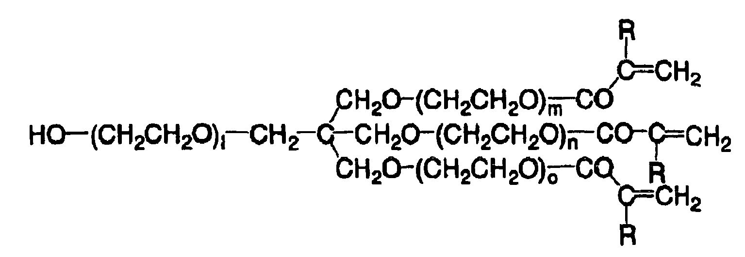
l, m, n and o: an integer of from 1 to 20
l, m, n and o: an integer of from 1 to 20
l, m, n and o: an integer of from 1 to 20
l, m, n and o: an integer of from 1 to 20


- Here, as a method for introducing a crosslinking group into the side chain of the polyurethane resin, a method for using a diisocyanate compound having a crosslinking group in the side chain thereof as the raw material for producing a polyurethane resin is suitable. Examples of a diisocyanate compound having a crosslinking group in the side chain thereof, which can be obtained by addition reaction of a triisocyanate compound and one equivalent of a crosslinking group-containing monofunctional alcohol or monofunctional amine compound will be given below, but it should not be construed that the invention is limited thereto.
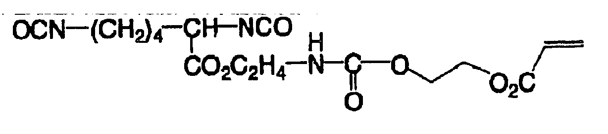


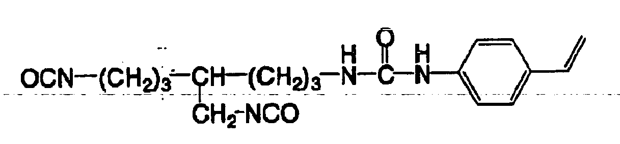


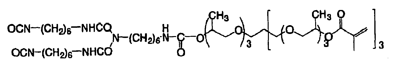
- As a method for introducing an unsaturated group into the side chain of the polyurethane resin, in addition to the foregoing methods, a method for using a diol compound containing an unsaturated group in the side chain thereof as the raw material for producing a polyurethane resin is suitable. As such a diol compound, commercially available products such as trimethylolpropane monoallyl ether may be employed. Compounds which are easily produced by reaction of a halogenated diol compound, a triol compound or an aminodiol compound with an unsaturated group-containing carboxylic acid, acid chloride, isocyanate, alcohol, amine, thiol or halogenated alkyl compound may also be employed. Specific examples of these compounds include the following compounds, but it should not be construed that the invention is limited thereto.


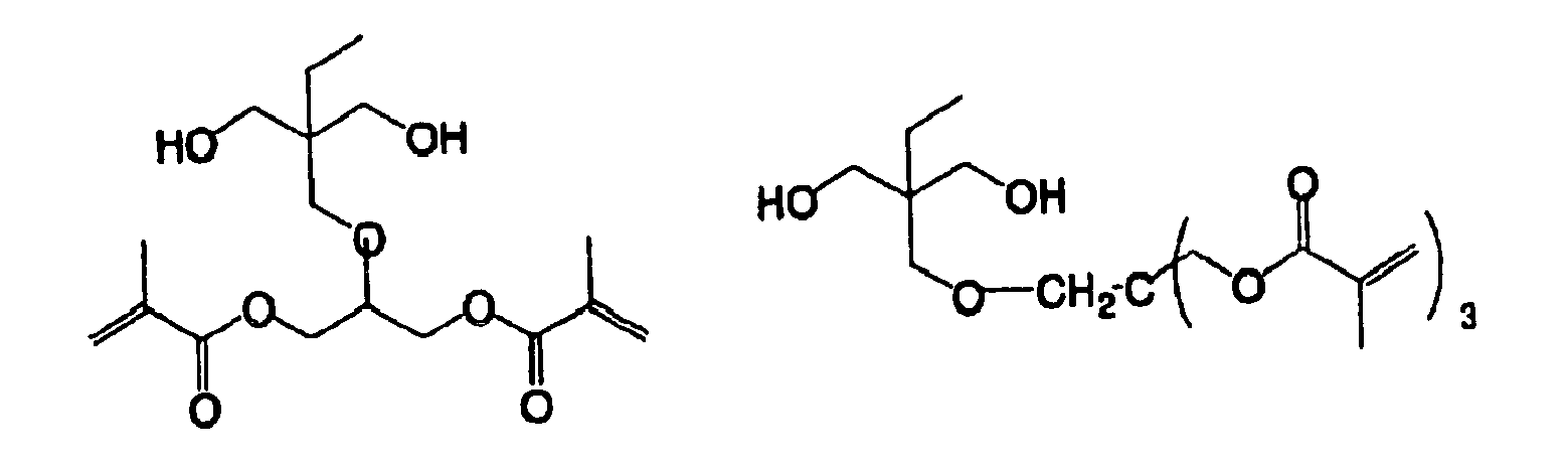


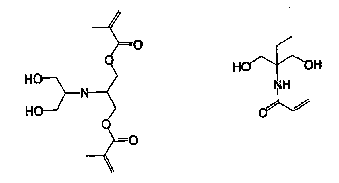


- In addition, examples of still other diol compounds include ethylene glycol compounds represented by the following formula (A').
HO-(CH2CH2O)n-H (A')
- In the foregoing formula (A'), n represents an integer of 1 or more.
- Furthermore, there are numerated hydroxyl group-terminated random copolymers and block copolymers of ethylene oxide and propylene oxide.
- In addition, ethylene oxide adducts of bisphenol A (the number of addition of ethylene oxide is 27 to 100), ethylene oxide adducts of bisphenol F (the number of addition of ethylene oxide is from 22 to 100), ethylene oxide adducts of hydrogenated bisphenol A (the number of addition of ethylene oxide is from 23 to 100), and ethylene oxide adducts of hydrogenated bisphenol F (the number of addition of ethylene oxide is from 18 to 100) can be used. More specifically, ethylene glycol compounds represented by the formula (A') are preferable in view of staining properties; ethylene glycol compounds wherein n is from 2 to 50 are more preferable; ethylene glycol compounds wherein n is from 3 to 30 are further preferable; and ethylene glycol compounds wherein n is from 4 to 10 are especially preferable.
- Specific examples thereof include 1,2-propylene glycol, di-1,2-propylene glycol, tri-1,2-propylene glycol, tetra-1,2-propylene glycol, hexa-1,2-propylene glycol, 1,3-propylene glycol, di-1,3-propylene glycol, tri-1,3-propylene glycol, tetra-1,3-propylene glycol, 1,3-butylene glycol, di-1,3-butylene glycol, tri-1,3-butylene glycol, hexa-1,3-butylene glycol, polypropylene glycol having an average molecular weight of 400, polypropylene glycol having an average molecular weight of 700, polypropylene glycol having an average molecular weight of 1,000, polypropylene glycol having an average molecular weight of 2,000, polypropylene glycol having an average molecular weight of 3,000, polypropylene glycol having an average molecular weight of 4,000, neopentyl glycol, 2-butene-1,4-diol, 2,2,4-trimethyl-1,3-pentanediol, 1,4-bis-β-hydroxyethoxycyclohexane, 1,4-butanediol, 1,5-pentanediol, 1,6-hexanediol, 1,7-heptanediol, 1,8-octanediol, cyclohexanedimethanol, tricyclodecanedimethanol, hydrogenated bisphenol A, hydrogenated bisphenol F, an ethylene oxide adduct of bisphenol A (the number of addition of ethylene oxide is not more than 26), an ethylene oxide adduct of bisphenol F (the number of addition of ethylene oxide is not more than 21), an ethylene oxide adduct of hydrogenated bisphenol A (the number of addition of ethylene oxide is not more than 22), an ethylene oxide adduct of hydrogenated bisphenol F (the number of addition of ethylene oxide is not more than 17), a propylene oxide adduct of bisphenol A, a propylene oxide adduct of bisphenol F, a propylene oxide adduct of hydrogenated bisphenol A, a propylene oxide adduct of hydrogenated bisphenol F, hydroquinonedihydroxyethyl ether, p-xylylene glycol, dihydroxyethylsulfone, bis(2-hydroxyethyl)-2,4-tolylene dicarbamate, 2,4-tolylene-bis-(2-hydroxyethyl carbamide), bis(2-hydroxyethyl)-m-xylylene dicarbamate, and bis(2-hydroxyethyl) isophthalate.
- Polyether diol compounds of a compound represented by the formula (A), (B), (C), (D) or (E) can also be suitably used.


HO-(CH2CH2CH2CH2-O)c-H (C)


- In the foregoing formulae, R6 represents a hydrogen atom or a methyl group, provided that in the formula (A), R6 represents a methyl group. X represents either one of the following groups:

- In the foregoing formulae, a, b, c, d, e, and f each represents an integer of 2 or more, and preferably an integer of from 2 to 100.
- In addition, polyester diol compounds represented by the formulae (11) and (12) can be enumerated as specific examples.


- In the foregoing formulae, L1, L2, and L3 may be the same or different and each a divalent aliphatic or aromatic hydrocarbon group; and L4 represents a divalent aliphatic hydrocarbon group. Preferably, L1, L2, and L3 each represents an alkylene group, an alkenylene group, an alkynylene group, or an arylene group; and L4 represents an alkylene group. Furthermore, L1, L2, L3, and L4 may contain other functional group which does not react with the isocyanate group, such as an ether group, a carbonyl group, an ester group, a cyano group, an olefin group, a urethane group, an amide group, an ureido group, and a halogen atom. n1 and n2 each represents an integer of 2 or more, and preferably an integer of from 2 to 100.
- In addition, polycarbonate diol compounds represented by the formula (13) can be enumerated as specific examples.

- In the foregoing formula (13), L5s may be the same or different and each represents a divalent aliphatic or aromatic hydrocarbon group. Preferably, L5 represents an alkylene group, an alkenylene group, an alknylene group, or an arylene group. Furthermore, L5 may contain other functional group which does not react with the isocyanate group, such as an ether group, a carbonyl group, an ester group, a cyano group, an olefin group, a urethane group, an amide group, an ureido group, and a halogen atom. n3 represents an integer of 2 or more, and preferably an integer of from 2 to 100.
- Specific examples of the diol compounds represented by the formulae (11), (12) and (13) include the following compounds. In the following specific examples, n represents an integer of 2 or more.


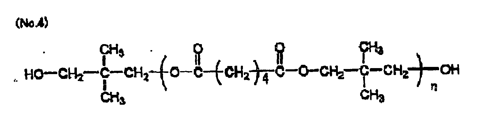





- Moreover, diol compounds which do not contain a carboxyl group and may contain other substituent which does not react with the isocyanate can be used.
- Such a diol compound includes the following compounds.
HO-L6-O-CO-L7-CO-O-L6-OH (14)
HO-L7-CO-O-L6-OH (15)
- In the foregoing formulae, L6 and L7 may be the same or different and each represents an optionally substituted divalent aliphatic hydrocarbon group, aromatic hydrocarbon group or heterocyclic group (examples of the substituent include an alkyl group, an aralkyl group, an aryl group, an alkoxy group, an aryloxy group, and a halogen atom (for example, -F, -Cl, -Br, and -I). If desired, L6 and L7 may each contain other functional group which does not react with the isocyanate group, such as a carbonyl group, an ester group, a urethane group, an amide group, and an ureido group. Incidentally, L6 and L7 may be taken together to form a ring.
- Specific examples of the compound represented by the formula (14) or (15) include the following compounds.


(No.105) HO―CH2CH2―O―CO―CH=CH―COO―CH2CH2―OH
(No.106) HO―CH2CH2―O―COC11H22COO―CH2CH2―OH
(No.107) HO―CH2CH2―O―COC12H24COO―CH2CH2―OH
(No.108) HO―CH2CH2―O―COC14H28COO―CH2CH2―OH

(No.110) HO-CH2CH2-O-CO-C≡C-COO-CH2CH2-OH


(No.113) HO-CH2CH2-O-CO-CH2-O-CH2-COO-CH2CH2-OH





(No. 123) HO-CH2CH2-COO-CH2CH2-OH


- The following diol compounds can also be suitably used.

HO-CH2-C≡C-CH2-OH (17)
HO-CH2-CH=CH-CH2-OH (18)
- In the foregoing formulae, R7 and R8 may be the same or different and each represents an optionally substituted alkyl group, and preferably an optionally substituted alkyl group having from 1 to 10 carbon atoms (examples of the substituent include a cyano group, a nitro group, a halogen atom (for example, -F, -Cl, -Br, and -I), a - CONH2 group, -COOR group, and an -OR group (wherein Rs may be the same or different and each represents an alkyl group having from 1 to 10 carbon atoms, an aryl group having from 7 to 15 carbon atoms, or an aralkyl group)).
- Specific examples of the diol compound represented by the formula (16) include the following compounds.
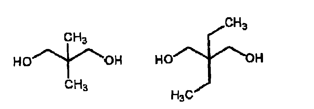

- 2-Butyne-1,4-diol is enumerated as the formula (17); and cis-2-butene-1,4-diol and trans-2-butene-1,4-diol are enumerated as the formula (18).
- Diol compounds represented by the following formulae (19) and (20) can also be suitably used.
HO-L8-NH-CO-L9-CO-NH-L8-OH (19)
HO-L9-CO-NH-L8-OH (20)
- In the foregoing formulae, L8 and L9 may be the same or different and each represents an optionally substituted divalent aliphatic hydrocarbon group, aromatic hydrocarbon group or heterocyclic group (examples of the substituent include an alkyl group, an aralkyl group, an aryl group, an alkoxy group, an aryloxy group, and a halogen atom (for example, -F, -Cl, -Br, and -I)). If desired, L8 and L9 may each contain other functional group which does not react with the isocyanate group, such as a carbonyl group, an ester group, a urethane group, an amide group, and an ureido group. Incidentally, L8 and L9 may be taken together to form a ring.
- Specific examples of the compound represented by the formula (19) or (20) include the following compounds.

(No203) HO-CH2CH2―NH―CO―CH=CH―CO―NH―CH2CH2―OH
(No204) HO―CH2CH2―NH―CO―C=C―CO―NH―CH2CH2―OH


(No.215) HO―CH2CH2―NH-CO-CH2―O―CH2―CO―NH―CH2CH2―OH


(No.218) HO―CH2CH2―NH―CO-CH2―S―CH2―CO―NH-CH2CH2―OH


- In addition, diol compounds represented by the following formulae (21) and (22) can be suitably used.
HO-Ar2-(L16-Ar3)n-OH (21)
HO-Ar2-L16-OH (22)
- In the foregoing formulae, L16 represents an optionally substituted divalent aliphatic hydrocarbon group (examples of the substituent include an alkyl group, an aralkyl group, an aryl group, an alkoxy group, an aryloxy group, and a halogen atom. If desired, L16 may contain other functional group which does not react with the isocyanate group, such as an ester group, a urethane group, an amide group, and an ureido group.
- Ar2 and Ar3 may be the same or different and each represents an optionally substituted divalent aromatic hydrocarbon group, and preferably an aromatic hydrocarbon group having from 6 to 15 carbon atoms; and n represents an integer of from 0 to 10.
- Specific examples of the diol compound represented by the formula (21) or (22) include the following compounds.
- Namely, examples include catechol, resorcin, hydroquinone, 4-methylcatechol, 4-t-butylcatechol, 4-acetylcatechol, 3-methoxycatechol, 4-phenylcatechol, 4-methylresorcin, 4-ethylresorcin, 4-t-butylresorcin, 4-hexylresorcin, 4-chlororesorcin, 4-benzylresorcin, 4-acetylresorcin, 4-carbomethoxyresorcin, 2-methylresorcin, 5-methylresorcin, t-butylhydroquinone, 2,5-di-t-butylhydroquinone, 2,5-di-t-amylhydroquinone, tetramethylhydroquinone, tetrachlorohydroquinone, methylcarbaminohydroquione, methylureidohydroquinone, methylthiohydroquinone, benzonorbornene-3,6-diol, bisphenol A, bisphenol S, 3,3'-dichlorobisphenol S, 4,4'-dihydroxybenzophenone, 4,4'-dihydroxybiphenyl, 4,4'-thiodiphenol, 2,2'-dihydroxydiphenylmethane, 3,4-bis(p-hydroxyphenyl)hexane, 1,4-bis(2-(p-hydroxyphenyl)propyl)-benzene, bis(4-hydroxyphenyl)methylamine, 1,3-dihydroxynaphthalene, 1,4-dihydroxynaphthalene, 1,5-dihydroxynaphthalene, 2,6-dihydroxynaphthalene, 1,5-dihydroxyanthraquinone, 2-hydroxybenzyl alcohol, 4-hydroxybenzyl alcohol, 2-hydroxy-3,5-di-t-butylbenzyl alcohol, 4-hydroxy-3,5-di-t-butylbenzyl alcohol, 4-hydroxyphenethyl alcohol, 2-hydroxyethyl-4-hydroxybenzoate, 2-hydroxyethyl-4-hydroxyphenyl acetate, and resorcin mono-2-hydroxyethyl ether. The following diol compounds can also be suitably used.
- In the polyurethane resin binder in the invention, a structure of a polyurethane resin as prepared by combining an amino group-containing compound represented by the following formula (31) or (32) and allowing it to react with a diisocyanate compound, thereby forming a urea structure may be incorporated.


- In the foregoing formulae, R106 and R106' may be the same or different and each represents a hydrogen atom or an optionally substituted alkyl, aralkyl or aryl group (examples of the substituent include an alkoxy group, a halogen atom (for example, -F, - Cl, -Br, and -I), an ester group, and a carboxyl group), and preferably a hydrogen atom or an alkyl group having from 1 to 8 carbon atoms or an aryl group having from 6 to 15 carbon atoms, each of which may contain a carboxyl group as a substituent. L17 represents an optionally substituted divalent aliphatic hydrocarbon group, aromatic hydrocarbon group or heterocyclic hydrocarbon group (examples of the substituent include an alkyl group, an aralkyl group, an aryl group, an alkoxy group, an aryloxy group, a halogen atom (for example, -F, -Cl, -Br, and -I), and a carboxyl group). If desired, L17 may contain other functional group which does not react with the isocyanate group, such as a carbonyl group, an ester group, a urethane group, and an amide group. Incidentally, two of R106, L17, and R106' may be taken together to form a ring.
- Specific examples of the compound represented by the formula (31) or (32) include the following compounds.
- Namely, examples include aliphatic diamine compounds (for example, ethylenediamine, propylenediamine, tetramethylenediamine, pentamethylenediamine, hexamethylenediamine, heptamethylenediamine, octamethylenediamine, dodecamethylenediamine, propane-1,2-diamine, bis(3-aminopropyl)methylamine, 1,3-bis(3-aminopropyl)tetramethylsiloxane, piperazine, 2,5-dimethylpiperazine, N-(2-aminoethyl)piperazine, 4-amino-2,2,6,6-tetramethylpiperidine, N,N-dimethylethylenediamine, lysine, L-cystine, and isophoronediamine); aromatic diamine compounds (for example, o-phenylenediamine, m-phenylenediamine, p-phenylenediamine, 2,4-tolylenediamine, benzidine, o-ditoluidine, o-dianisidine, 4-nitro-m-phenylenediamine, 2,5-dimethoxy-p-phenylenediamine, bis(4-aminophenyl)sulfone, 4-carboxy-o-phenylenediamine, 3-carboxy-m-phenylenediamine, 4,4'-diaminophenyl ether, and 1,8-naphthalenediamine); heterocyclic amine compounds (for example, 2-aminoimidazole, 3-aminotriazole, 5-amino-1H-tetrazole, 4-aminopyrazole, 2-aminobenzimidazole, 2-amino-5-carboxy-triazole, 2,4-diamino-6-methyl-S-triazine, 2,6-diaminopyridine, L-histidine, DL-tryptophan, and adenine); and amino alcohol or amino phenol compounds (for example, ethanolamine, N-methylethanolamine, N-ethylethanolamine, 1-amino-2-propanol, 1-amino-3-propanol, 2-aminoethoxyethanol, 2-aminothioethoxyethanol, 2-amino-2-methyl-1-propanol, p-aminophenol, m-aminophenol, o-aminophenol, 4-methyl-2-aminophenol, 2-chloro-4-aminophenol, 4-methoxy-3-aminophenol, 4-hydroxybenzylamine, 4-amino-1-naphthol, 4-aminosalicylic acid, 4-hydroxy-N-phenylglycine, 2-aminobenzyl alcohol, 4-aminophenethyl alcohol, 2-carboxy-5-amino-1-naphthol, and L-tyrosine).
- In addition to the foregoing polyurethane resins as obtained by introducing a crosslinking group in the side chain thereof at the time of synthesis of polyurethane, polyurethane resins as obtained by introducing a crosslinking group into a carboxyl group-containing polyurethane by polymeric reaction as described in JP-A-2003-270775 can be used as the polymer binder according to the invention.
- The (meth)acrylic resin having a crosslinking group in the side chain thereof used in the invention will be hereunder described.
- As the (meth)acrylic resin having a crosslinking group in the side chain thereof which is used in the invention, a resin containing a repeating unit represented by the following formula (i) is preferable from the viewpoint of developability.
- The resin containing a repeating unit represented by the formula (i) will be hereunder properly referred to as a "specific (meth)acrylic resin" and described below in detail.

- In the foregoing formula (i), R1 represents a hydrogen atom or a methyl group; R2 represents a connecting group constituted of one or more atoms selected from the group consisting of a carbon atom, a hydrogen atom, an oxygen atom, a nitrogen atom, and a sulfur atom; A represents an oxygen atom or -NR3-; R3 represents a hydrogen atom or a monovalent hydrocarbon group having from 1 to 10 carbon atoms; and n represents an integer of from 1 to 5.
- First of all, R1 in the formula (i) represents a hydrogen atom or a methyl group, and especially preferably a methyl group.
- The connecting group represented by R2 in the formula (i) is constituted of one or more atoms selected from the group consisting of a carbon atom, a hydrogen atom, an oxygen atom, a nitrogen atom, and a sulfur atom, and it is preferable that the number of atoms exclusive of its substituent is from 2 to 82. Specifically, the number of atoms constituting the principal skeleton of the connecting group represented by R2 is preferably from 1 to 30, more preferably from 3 to 25, further preferably from 4 to 20, and most preferably from 5 to 10. Incidentally, the term "principal skeleton of the connecting group" as referred to in the invention refers to atoms or an atomic group to be used only for connecting A to the terminal COOH in the formula (i); and in particular, when plural connecting routes are present, this term refers to atoms or an atomic group for constituting a route where the number of atoms to be used is the smallest. Accordingly, in the case where a cyclic structure is contained in the connecting group, the number of atoms to be counted varies depending upon its connecting site (for example, o-, m-, and p-).
- Furthermore, more specifically, examples of the connecting group include an alkylene, a substituted alkylene, an arylene, and a substituted arylene. The connecting group may have a structure in which a plural number of such divalent groups are connected to each other via an amide bond or an ester bond.
- Examples of the connecting group of a chain structure include ethylene and propylene. Structures in which such alkylenes are connected to each other via an ester bond can also be enumerated as a preferred structure.
- Above all, it is preferable that the connecting group represented by R2 in the formula (i) is a hydrocarbon group having a valence of (n + 1) and having an aliphatic cyclic structure having from 3 to 30 carbon atoms. More specifically, a hydrocarbon group having a valence of (n + 1) resulting from elimination of (n + 1) hydrogen atoms on arbitrary carbon atoms constituting a compound having an aliphatic cyclic structure, which may be substituted with one or more arbitrary substituents, such as cyclopropane, cyclopentane, cyclohexane, cycloheptane, cyclooctane, cyclodecane, dicyclohexyl, tercyclohexyl, and norbornane can be enumerated. Furthermore, it is preferable that R2 has from 3 to 30 carbon atoms including the substituent.
- One or more arbitrary carbon atoms of a compound constituting an aliphatic cyclic structure may be substituted with a hetero atom selected from a nitrogen atom, an oxygen atom, and a sulfur atom. In view of printing resistance, R2 is preferably a hydrocarbon group having a valence of (n + 1) and having an optionally substituted aliphatic cyclic structure, which has from 5 to 30 carbon atoms and contains two or more rings, such as fused polycyclic aliphatic hydrocarbons, crosslinked alicyclic hydrocarbons, spiro aliphatic hydrocarbons, and aliphatic hydrocarbon ring agglomerations (in which plural rings are connected to each other via a bond or a connecting group). In this case, the number of carbon atoms is one including the number of carbon atoms which the substituent has, too.
- As the connecting group represented by R2, a connecting group having the number of atoms constituting the principal skeleton of the connecting group of from 5 to 10 is preferable. With respect to the structure, a connecting group having a chain structure and containing an ester bond in the structure thereof and a connecting group having the foregoing cyclic structure are preferable.
- As the substituent which can be introduced into the connecting group represented by R2, a monovalent non-metallic atomic group excluding hydrogen can be enumerated. Examples thereof include a halogen atom (for example, -F, -Br, -Cl, and -I), a hydroxyl group, an alkoxy group, an aryloxy group, a mercapto group, an alkylthio group, an arylthio group, an alkyldithio group, an aryldithio group, an amino group, an N-alkylamino group, an N,N-dialkylamino group, an N-arylamino group, an N,N-diarylamino group, an N-alkyl-N-arylamino group, an acyloxy group, a carbamoyloxy group, an N-alkylcarbamoyloxy group, an N-arylcarbamoyloxy group, an N,N-dialkylcarbamoyloxy group, an N,N-diarylcarbamoyloxy group, an N-alkyl-N-arylcarbamoyloxy group, an alkylsulfoxy group, an arylsulfoxy group, an acylthio group, an acylamino group, an N-alkylacylamino group, an N-arylactylamino group, an ureido group, an N'-alkylureido group, an N',N'-dialkylureido group, an N'-arylureido group, an N',N'-diarylureido group, an N'-alkyl-N'-arylureido group, an N-alkylureido group, an N-arylureido group, an N'-alkyl-N-alkylureido group, an N'-alkyl-N-arylureido group, an N',N'-dialkyl-N-alkylureido group, an N',N'-dialkyl-N-arylureido group, an N'-aryl-N-alkylureido group, an N'-aryl-N-arylureido group, an N',N'-diaryl-N-alkylureido group, an N',N'-diaryl-N-arylureido group, an N'-alkyl-N'-aryl-N-alkylureido group, an N'-alkyl-N'-aryl-N-arylureido group, an alkoxycarbonylamino group, an aryloxycarbonylamino group, an N-alkyl-N-alkoxycarbonylamino group, an N-alkyl-N-aryloxycabonylamino group, an aryl-N-alkoxycarbonylamino group, an N-aryl-N-aryloxycarbonylamino group, a formyl group, an acyl group, a carboxyl group and its conjugated base group, an alkoxycarbonyl group, an aryloxycarbonyl group, a carbamoyl group, an N-alkylcarbamoyl group, an N,N-dialkylcarbamoyl group, an N-arylcarbamoyl group, an N,N-diarylcarbamoyl group, an N-alkyl-N-arylcarbamoyl group, an alkylsulfinyl group, an arylsulfinyl group, an alkylsulfonyl group, an arylsulfonyl group, a sulfo group (-SO3H) and its conjugated base group, an alkoxy-sulfonyl group, an aryloxysulfonyl group, a sulfinamoyl group, an N-alkylsulfinamoyl group, an N,N-dialkylsulfinamoyl group, an N-arylsulfinamoyl group, an N,N-diarylsulfinamoyl group, an N-alkyl-N-arylsulfinamoyl group, a sulfamoyl group, an N-alkylsulfamoyl group, an N,N-dialkylsulfamoyl group, an N-arylsulfamoyl group, an N,N-diarylsulfamoyl group, an N-alkyl-N-arylsulfamoyl group, an N-acylsulfamoyl group and its conjugated base group, an N-alkylsulfonylsulfamoyl group (-SO2NHSO2(alkyl)) and its conjugated base group, an N-arylsulfonylsulfamoyl group (-SO2NHSO2(aryl)) and its conjugated base group, an N-alkylsulfonylcarbamoyl group (-CONHSO2(alkyl)) and its conjugated base group, an N-arylsulfonylcarbamoyl group (-CONHSO2(aryl)) and its conjugated base group, an alkoxysilyl group (-Si(Oalkyl)3), an aryloxysilyl group (-Si(Oaryl)3), a hydroxysilyl group (-Si(OH)3) and its conjugated base group, a phosphono group (-PO3H2) and its conjugated base group, a dialkylphosphono group (-PO3(alkyl)2), a diarylphosphono group (-PO3(aryl)2), an alkylarylphosphono group (-PO3(alkyl)(aryl)), a monoalkylphosphono group (-PO3H(alkyl)) and its conjugated base group, a monoarylphosphono group (-PO3H(aryl)) and its conjugated base group, a phosphonoxy group (-OPO3H2) and its conjugated base group, a dialkylphosphonoxy group (-OPO3(alkyl)2), a diarylphosphonoxy group (-OPO3(aryl)2), an alkylarylphosphonoxy group (-OPO3(alkyl)(aryl)), a monoalkylphosphonoxy group (-OPO3H(alkyl)) and its conjugated base group, a monoarylphosphonoxy group (-OPO3H(aryl)) and its conjugated base group, a cyano group, a nitro group, a dialkylboryl group (-B(alkyl)2), a diarylboryl group (-B(aryl)2), an alkylarylboryl group (-B(alkyl)(aryl)), a dihydroxyboryl group (-B(OH)2) and its conjugated base group, an alkylhydroxyboryl group (-B(alkyl)(OH)) and its conjugated base group, an arylhydroxyboryl group (-B(aryl)(OH)) and its conjugated base group, an aryl group, an alkenyl group, and an alkynyl group.
- In the photosensitive lithographic printing plate of the invention, a hydrogencontaining substituent which can undergo hydrogen bonding, and especially an acidic substituent having an acid dissociation constant (pKa) lower than carboxylic acids are not preferable because they are liable to lower the printing resistance, an aspect of which, however, varies depending upon the design of the photosensitive layer. On the other hand, a halogen atom and a hydrophobic substituent such as a hydrocarbon group (for example, an alkyl group, an aryl group, an alkenyl group, and an alkynyl group), an alkoxy group, and an aryloxy group are preferable because they are liable to enhance the printing resistance. In particular, in the case where the cyclic structure is a monocyclic aliphatic hydrocarbon constructed of not more than 6 members, such as cyclopentane and cyclohexane, it is preferable that such a hydrophobic substituent is contained. If possible, such substituents may be taken together or bonded to a hydrocarbon group as substituted to form a ring. The substituent may be further substituted.
- When A in the formula (i) is NR3-, R3 represents a hydrogen atom or a monovalent hydrocarbon group having from 1 to 10 carbon atoms. Examples of the monovalent hydrocarbon group having from 1 to 10 carbon atoms as represented by R3 include an alkyl group, an aryl group, an alkenyl group, and an alkynyl group.
- Specific examples of the alkyl group include linear, branched or cyclic alkyl groups having from 1 to 10 carbon atoms such as a methyl group, an ethyl group, a propyl group, a butyl group, a pentyl group, a hexyl group, a heptyl group, an octyl group, a nonyl group, a decyl group, an isopropyl group, an isobutyl group, a sec-butyl group, a tert-butyl group, an isopentyl group, a neopentyl group, a 1-methylbutyl group, an isohexyl group, a 2-ethylhexyl group, a 2-methylhexyl group, a cyclopentyl group, a cyclohexyl group, a 1-adamantyl group, and a 2-norbornyl group.
- Specific examples of the aryl group include aryl groups having from 1 to 10 carbon atoms (for example, a phenyl group, a naphthyl group, and an indenyl group) and heteroaryl groups having from 1 to 10 carbon atoms and containing one hetero atom selected from the group consisting of a nitrogen atom, an oxygen atom, and a sulfur atom (for example, a furyl group, a thienyl group, a pyrrolyl group, a pyridyl group, and a quinolyl group).
- Specific examples of the alkenyl group include linear, branched or cyclic alkenyl groups having from 1 to 10 carbon atoms such as a vinyl group, a 1-propenyl group, a 1-butenyl group, a 1-methyl-1-propenyl group, a 1-cyclopentenyl group, and a 1-cyclohexenyl group.
- Specific examples of the alkynyl group include alkynyl groups having from 1 to 10 carbon atoms such as an ethynyl group, a 1-propynyl group, a 1-butynyl group, and a 1-octynyl group. The substituent which R3 may contain is the same as the substituent which R2 can introduce. However, the number of carbon atoms of R3 is from 1 to 10 inclusive of the number of carbon atoms of the substituent.
- A in the formula (i) is preferably an oxygen atom or -NH- because of easiness of the synthesis.
- n in the formula (i) represents an integer of from 1 to 5, and preferably 1 in view of printing resistance.
- Preferred specific examples of the repeating unit represented by the formula (i) will be given below, but it should not be construed that the invention is limited thereto.


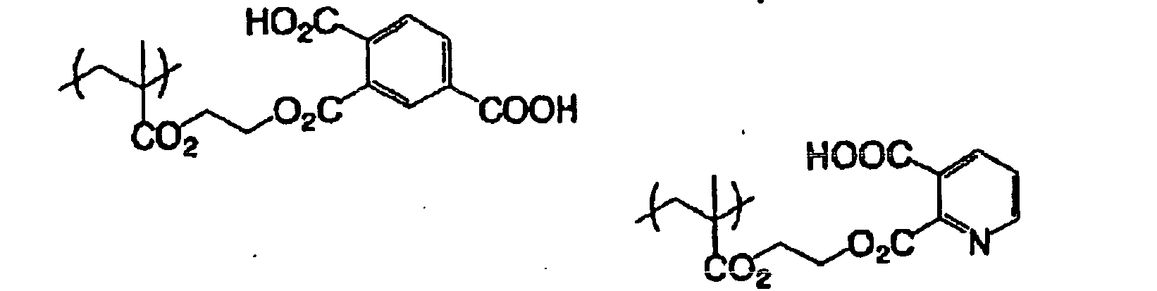










- The specific (meth)acrylic resin for use in the present invention is preferably a copolymer obtained by combining a repeating unit represented by formula (i), a repeating unit having a crosslinking group in the side chain and, if desired, other copolymerization components. As for the repeating unit represented by formula (i), one kind of the repeating unit may be contained in the specific (meth)acrylic resin, or two or more kinds of the repeating units may be contained. The total content of the repeating unit represented by formula (i) is appropriately selected according to the structure of the repeating unit, the design of the polymerizable compound, or the like, but the total content is preferably from 1 to 99 mol%, more preferably from 5 to 40 mol%, still more preferably from 5 to 20 mol%, based on the total molar amount of the resin components.
- Examples of the polymer having an ethylenically unsaturated bond as a crosslinking group in the side chain include a polymer which is a polymer of acrylic or methacrylic acid ester or amide and in which the ester or amide residue (R in -COOR or -CONHR) has an ethylenically unsaturated bond.
- Examples of the residue (R above) having an ethylenically unsaturated bond include -(CH2)nCR1=CR2R3, -(CH20)nCH2CR1=CR2R3, -(CH2CH2O)nCH2CR1=CR2R3, -(CH2)nNH-CO-O-CH2CR1=CR2R3, -(CH2)n-O-CO-CR1=CR2R3 and -(CH2CH2O)2-X (wherein R1 to R3 each represents a hydrogen atom, a halogen atom or an alkyl, aryl, alkoxy or aryloxy group having from 1 to 20 carbon atoms, R1 may combine with R2 or R3 to form a ring, n represents an integer of 1 to 10, and X represents a dicyclopentadienyl residue).
- Specific examples of the ester residue include -CH2CH=CH2 (described in
JP-B-7-21633 - Specific examples of the amide residue include -CH2CH=CH2, -CH2CH2-Y (wherein Y represents a cyclohexene residue) and -CH2CH2-OCO-CH=CH2.
- In the binder polymer having a crosslinking property, for example, a free radical (a polymerization initiating radical or a radical grown in the process of polymerization of a polymerizable compound) is added to the crosslinking functional group to cause addition-polymerization between polymers directly or through a polymerization chain of the polymerizable compound, as a result, crosslinking is formed between polymer molecules and thereby curing is effected. Alternatively, an atom (for example, a hydrogen atom on the carbon atom adjacent to the functional crosslinking group) in the polymer is withdrawn by a free radical to produce a polymer radical and the polymer radicals combine with each other to form crosslinking between polymer molecules, thereby effecting curing.
- The content of the crosslinking group (content of the radical-polymerizable unsaturated double bond determined by iodine titration) in the binder polymer is preferably from 0.1 to 10.0 mmol, more preferably from 1.0 to 7.0 mmol, most preferably from 2.0 to 5.5 mmol, per g of the binder polymer. Within this range, good sensitivity and good storage stability are obtained.
- As for other copolymerization components, a conventionally known monomer may be used without limitation as long as it is a radical-polymerizable monomer. Specific examples thereof include monomers described in Kobunshi Data Handbook-Kiso Hen- (Polymer Data Handbook -Basic Edition-), compiled by The Society of Polymer Science, Japan, Baifukan (1986). One of these copolymerization components may be used, or two or more thereof may be used in combination.
- The amount of the polymer binder having a crosslinking group in the photopolymerizable composition may be appropriately selected but is usually from 10 to 90 mass%, preferably from 20 to 80 mass%, more preferably from 30 to 70 mass%, based on the entire mass of nonvolatile components in the photopolymerizable composition.
- Also, the ratio of the photopolymerizable ethylenically unsaturated bond-containing compound and the polymer binder having a crosslinking group is, in terms of the mass ratio, preferably from 1/9 to 9/1, more preferably from 2/8 to 8/2, still more preferably from 3/7 to 7/3.
- Together with the polymer binder having a crosslinking group, one or more kinds of other resins may be used as the binder in combination.
- The resin used in combination is generally added in an amount of 50 mass% or less, preferably 30 mass% or less, based on the mass of the polymer binder having a crosslinking group.
- The molecular weight of the polymer binder for use in the present invention is appropriately selected in view of image formability and press life. The mass average molecular weight is preferably from 2,000 to 1,000,000, more preferably from 5,000 to 500,000, still more preferably from 10,000 to 200,000.
- The polymer binder for use in the present invention may be used as a sole polymer binder, or two or more kinds of the polymer binders may be used in combination. Also, the polymer binder may be used as a mixture by using one or more kinds of other binder polymers having no crosslinking group in combination. As for the binder polymer which can be used in combination, a conventionally known alkalisoluble or swellable binder may be used without limitation. More specifically, for example, an acryl main chain binder or a urethane binder, which are often used in this industry, is preferably used.
- The total amount of the polymer binder and the binder polymer which may be used in combination, in the photosensitive layer, may be appropriately selected but is usually from 10 to 90 mass%, preferably from 20 to 80 mass%, more preferably from 30 to 70 mass%, based on the total mass of nonvolatile components in the photosensitive layer.
- The polymerization initiation system contained in the photosensitive layer for use in the present invention may be either a photopolymerization initiation system (photon-mode initiation system) or a heat-mode initiation system.
- The photopolymerization initiation system (initiator) contained in the photosensitive layer of the photosensitive lithographic printing plate of the present invention may be appropriately selected from various photopolymerization initiators or a combination system of two or more photopolymerization initiators (photo-initiation system) known, for example, in patents and publications, according to the wavelength of the light source used. Specific examples thereof include, but are not limited to, the followings.
- In the case of using a light source of 400 nm or more, such as visible ray, Ar laser, second harmonic of semiconductor laser, or SHG-YAG laser, various photoinitiators have been proposed. Examples thereof include a certain kind of a photoreducing dye, such as Rose Bengal, eosin and erythrosine, described in
U.S. Patent 2,850,445 , and a combination system of a dye and an initiator, such as a composite initiation system of a dye and an amine (see,JP-B-44-20189 JP-B-45-37377 JP-B-47-2528 JP-A-54-155292 JP-A-2-63054 JP-A-62-143044 JP-A-62-150242 JP-A-64-13140 JP-A-64-13141 JP-A-64-13142 JP-A-64-13143 JP-A-64-17048 JP-A-1-229003 JP-A-1-298348 JP-A-1-138204 JP-A-4-221958 JP-A-4-219756 JP-A-6-295061 JP-A-8-334897 - Furthermore, with recent development of a laser having a wavelength of 400 to 410 nm (violet laser), a photo-initiation system responding thereto and showing high sensitivity to light at the wavelength of 450 nm or less has been developed and such a photo-initiation system may also be used. Examples thereof include a cationic dye/borate system (see, JP-A-11-84647), a merocyanine dye/titanocene system (see, JP-A-2000-147763), and a carbazole-type coloring matter/titanocene system (see, JP-A-2001-42524). In the present invention, a titanocene compound and a hexaarylbiimidazole compound are particularly preferred.
- As for the titanocene compound, various titanocene compounds may be used, but an appropriate titanocene compound may be selected from those described in JP-A-59-152396 and JP-A-61-151197. Specific examples thereof include dicyclopentadienyl-Ti-dichloride, dicyclopentadienyl-Ti-bisphenyl, dicyclopentadienyl-Ti-bis-2,3,4,5,6-pentafluorophen-1-yl, dicyclopentadienyl-Ti-bis-2,3,5,6-tetrafluorophen-1-yl, dicyclopentadienyl-Ti-bis-2,4,6-trifluorophen-1-yl, dicyclopentadienyl-Ti-bis-2,6-difluorophen-1-yl, dicyclopentadienyl-Ti-bis-2,4-difluorophen-1-yl, dimethylcyclopentadienyl-Ti-bis-2,3,4,5,6-pentafluorophen-1-yl, dimethylcyclopentadienyl-Ti-bis-2,6-difluorophen-1-yl and dicyclopentadienyl-Ti-bis-2,6-difluoro-3-(pyr-1-lyl)-phen-1-yl.
- As for the hexaarylbiimidazole compound, various hexaarylbiimidazole compounds may be used, but examples thereof include lophine dimers described in JP-B-45-37377 and JP-B-44-86516, such as 2,2'-bis(o-chlorophenyl)-4,4',5,5'-tetraphenylbiimidazole, 2,2'-bis(o-bromophenyl)-4,4',5,5'-tetraphenylbiimidazole, 2,2'-bis(o,p-dichlorophenyl)-4,4',5,5'-tetraphenylbiimidazole, 2,2'-bis(o-chlorophenyl)-4,4',5,5'-tetra(m-methoxyphenyl)biimidazole, 2,2'-bis(o,o'-dichlorophenyl)-4,4',5,5'-tetraphenylbiimidazole, 2,2'-bis(o-nitrophenyl)-4,4',5,5'-tetraphenylbiimidazole, 2,2'-bis(o-methylphenyl)-4,4',5,5'-tetraphenylbiimidazole, 2,2'-bis(o-trifluorophenyl)-4,4',5,5'-tetraphenylbiimidazole, 2,2'-bis(o,m-dichlorophenyl)-4,4',5,5'-tetraphenylbiimidazole and 2,2'-bis(o-chlorophenyl)-4,4',5,5'-tetra(p-bromophenyl)biimidazole.
- Among these, preferred are 2,2'-bis(o-chlorophenyl)-4,4',5,5'-tetraphenylbiimidazole, 2,2'-bis(o,m-dichlorophenyl)-4,4',5,5'-tetraphenylbiimidazole and 2,2'-bis(o-chlorophenyl)-4,4',5,5'-tetra(p-bromophenyl)biimidazole.
- Furthermore, if desired, a compound called chain transfer agent or sensitization aid known to more enhance the photo-initiation ability when used in combination with a photopolymerization initiator may be used in the above-described photopolymerization initiation system. Examples of such a compound include a hydrogen-donating compound such as thiol compound (e.g., 2-mercaptobenzothiazole, 2-mercaptobenzimidazole, 2-mercaptobenzoxazole) and amine compound (e.g., N-phenylglycin, N,N-dialkylamino-aromatic alkyl ether).
- The photopolymerization initiator (initiation system) is used in an amount of 0.05 to 100 parts by mass, preferably from 0.1 to 70 parts by mass, more preferably from 0.2 to 50 parts by mass, per 100 parts by mass of an ethylenically unsaturated compound described later.
- A heat-mode polymerization system may also be applied to the photosensitive lithographic printing plate of the present invention. In the heat-mode polymerization system, a combination of an infrared absorbent and a polymerization initiator is used in place of the above-described photopolymerization initiation system. As for the hydrogen-donating compound or chain transfer agent for accelerating the polymerization, a compound described in connection with the photopolymerization system may be appropriately used, if desired.
- It is essential to use an infrared absorbent in the photosensitive composition of the present invention. The infrared absorbent has a function of converting the absorbed infrared ray into heat. By the effect of heat generated here, the polymerization initiator (radical generator) described later is thermally decomposed to generate a radical. The infrared absorbent for use in the present invention is preferably a dye or pigment having absorption maximum in the wavelength region from 760 to 1,200 nm.
- As for the dye, commercially available dyes and known dyes, for example, those described in publications such as Senryo Binran (Handbook of Dyes), compiled by The Society of Synthetic Organic Chemistry, Japan (1970) may be used. Specific examples thereof include dyes such as azo dye, metal complex salt azo dye, pyrazolone azo dye, naphthoquinone dye, anthraquinone dye, phthalocyanine dye, carbonium dye, quinoneimine dye, methine dye, cyanine dye, squarylium dye, pyrylium salt and metal thiolate complex.
- Preferred examples of the dye include cyanine dyes described in
JP-A-58-125246 JP-A-59-84356 JP-A-60-78787 JP-A-58-173696 JP-A-58-181690 JP-A-58-194595 JP-A-58-112793 JP-A-58-224793 JP-A-59-48187 JP-A-59-73996 JP-A-60-52940 JP-A-60-63744 JP-A-58-112792 British Patent 434,875 - Also, near infrared absorbing sensitizers described in
U.S. Patent 5,156,938 may be suitably used. Furthermore, substituted arylbenzo(thio)pyrylium salts described inU.S. Patent 3,881,924 , trimethinethiapyrylium salts described inJP-A-57-142645 U.S. Patent 4,327,169 ), pyrylium-based compounds described inJP-A-58-181051 JP-A-58-220143 JP-A-59-41363 JP-A-59-84248 JP-59-84249 JP-A-59-146063 JP-A-59-146061 JP-A-59-216146 U.S. Patent 4,283,475 , and pyrylium compounds described inJP-B-5-13514 JP-B-5-19702 U.S. Patent 4,756,993 . - Also, other preferred examples of the infrared absorbing dye for use in the present invention include specific indolenine cyanine dyes described in
Japanese Patent Application Nos. 2001-6326 2001-237840 


- Among these dyes, preferred are a cyanine dye, a squarylium dye, a pyrylium salt, a nickel thiolate complex and an indolenine cyanine dye, more preferred are a cyanine dye and an indolenine cyanine dye. A particularly preferred example of the dye is a cyanine dye represented by the following formula (a):

- In formula (a), X1 represents a hydrogen atom, a halogen atom, -NPh2, X2-L1 or a group shown below (wherein X2 represents an oxygen atom, a nitrogen atom or a sulfur atom, L1 represents a hydrocarbon group having from 1 to 12 carbon atoms, an aromatic ring having a heteroatom, or a hydrocarbon group having from 1 to 12 carbon atoms and containing a heteroatom (the heteroatom as used herein indicates N, S, O, a halogen atom or Se), Xa - has the same definition as Z1- described later, and Ra represents a substituent selected from a hydrogen atom, an alkyl group, an aryl group, a substituted or unsubstituted amino group and a halogen atom).

- R1 and R2 each independently represents a hydrocarbon group having from 1 to 12 carbon atoms. In view of storage stability of the coating solution for recording layer, R1 and R2 each is preferably a hydrocarbon group having 2 or more carbon atoms, and R1 and R2 are more preferably combined with each other to form a 5- or 6-membered ring.
- Ar1 and Ar2 may be the same or different and each represents an aromatic hydrocarbon group which may have a substituent. Preferred examples of the aromatic hydrocarbon group include a benzene ring and a naphthalene ring. Preferred examples of the substituent include a hydrocarbon group having 12 or less carbon atoms, a halogen atom and an alkoxy group having 12 or less carbon atoms. Y1 and Y2 may be the same or different and each represents a sulfur atom or a dialkylmethylene group having 12 or less carbon atoms. R3 and R4 may be the same or different and each represents a hydrocarbon group having 20 or less carbon atoms, which may have a substituent. Preferred examples of the substituent include an alkoxy group having 12 or less carbon atoms, a carboxyl group and a sulfo group. R5, R6, R7 and R8 may be the same or different and each represents a hydrogen atom or a hydrocarbon group having 12 or less carbon atoms and in view of availability of the raw material, preferably a hydrogen atom. Za- represents a counter anion, but when the cyanine dye represented by formula (a) has an anionic substituent in its structure and neutralization of electric charge is not necessary, Za- is not present. In view of storage stability of the coating solution for recording layer, Za- is preferably halogen ion, perchlorate ion, tetrafluoroborate ion, hexafluorophosphate ion or sulfonate ion, more preferably perchlorate ion, hexafluorophosphate ion or arylsulfonate ion.
- Specific examples of the cyanine dye represented by formula (a), which can be suitably used in the present invention, include those described in paragraphs [0017] to [0019] of
JP-A-2001-133969 - Other preferred examples include specific indolenine cyanine dyes described in
Japanese Patent Application Nos. 2001-6326 2001-237840 - As for the pigment used in the present invention, commercially available pigments and pigments described in Color Index (C.I.) Binran (C.I. Handbook), Saishin Ganryo Binran (Handbook of Latest Pigments), compiled by Nippon Ganryo Gijutsu Kyokai (1977), Saishin Ganryo Oyo Gijutsu (Latest Pigment Application Technology), CMC Shuppan (1986), and Insatsu Ink Gijutsu (Printing Ink Technology), CMC Shuppan (1984) can be used.
- The kind of the pigment includes black pigment, yellow pigment, orange pigment, brown pigment, red pigment, violet pigment, blue pigment, green pigment, fluorescent pigment, metal powder pigment and polymer bond pigment. Specific examples of the pigment which can be used include an insoluble azo pigment, an azo lake pigment, a condensed azo pigment, a chelate azo pigment, a phthalocyanine-based pigment, an anthraquinone-based pigment, a perylene- or perynone-based pigment, a thioindigo-based pigment, a quinacridone-based pigment, a dioxazine-based pigment, an isoindolinone-based pigment, a quinophthalone-based pigment, a dyed lake pigment, an azine pigment, a nitroso pigment, a nitro pigments, a natural pigment, a fluorescent pigment, an inorganic pigment and carbon black. Among these pigments, carbon black is preferred.
- These pigments may or may not be surface-treated before use. Examples of the method for surface treatment include a method of coating the surface with resin or wax, a method of attaching a surfactant, and a method of binding a reactive substance (for example, a silane coupling agent, an epoxy compound or an isocyanate) to the pigment surface. These surface-treating methods are described in Kinzoku Sekken no Seishitsu to Oyo (properties and Application of Metal Soap), Saiwai Shobo, Insatsu Ink Gijutsu (Printing Ink Technology), CMC Shuppan (1984), and Saishin Ganryo Oyo Gijutsu (Latest Pigment Application Technology), CMC Shuppan (1986).
- The particle diameter of the pigment is preferably from 0.01 to 10 µm, more preferably from 0.05 to 1 µm, still more preferably from 0.1 to 1 µm. If the particle diameter of the pigment is less than 0.01 µm, this is not preferred in view of stability of the dispersion in the coating solution for photosensitive layer, and a particle diameter exceeding 10 µm is not preferred in view of uniformity of the photosensitive layer.
- As for the method of dispersing the pigment, a known dispersion technique employed in the production of ink or toner may be used. Examples of the disperser include an ultrasonic disperser, a sand mill, an attritor, a pearl mill, a super-mill, a ball mill, an impeller, a disperser, a KD mill, a colloid mill, a dynatron, a three-roll mill and a pressure kneader. These are described in detail in Saishin Ganryo Oyo Gijutsu (Latest Pigment Application Technology), CMC Shuppan (1986).
- In the case of applying the photosensitive composition of the present invention to a photosensitive lithographic printing plate, the infrared absorbent may be added together with other components in the same layer or may be added to a layer provided separately, but the infrared absorbent is preferably added such that when a negative lithographic printing plate precursor is produced, the absorbancy of the photosensitive layer at a maximum absorption wavelength in the wavelength range from 760 to 1,200 nm becomes from 0.5 to 1.2, more preferably from 0.6 to 1.15, as measured by a reflection measuring method. If the absorbancy is out of this range, the strength of the image area is reduced and the number of printed sheets at the printing decreases. The cause thereof is not clearly known, but it is presumed that if the absorbancy is less than 0.5, the infrared ray irradiated cannot be satisfactorily absorbed, as a result, radical polymerization does not sufficiently proceed in the entire photosensitive layer, whereas if the absorbancy exceeds 1.2, the ultraviolet ray is absorbed only in the outermost surface of the photosensitive layer and fails in reaching the vicinity of the support, as a result, radical polymerization does not occur in the vicinity of the support and the adhesive strength between the support and the photosensitive layer becomes insufficient.
- The absorbancy of the photosensitive layer can be adjusted by the amount of the infrared absorbent added to the photosensitive layer and the thickness of the photosensitive layer. The absorbancy can be measured by an ordinary method. Examples of the measuring method include a method where a photosensitive layer having a thickness appropriately decided within the range of the dry coated amount necessary as a lithographic printing plate is formed on a reflective support such as aluminum and the reflection density is measured by an optical densitometer, and a method of measuring the absorbancy by a spectrophotometer according to a reflection method using an integrating sphere.
- In the heat-mode system, a polymerization initiator is used in combination with the above-described infrared absorbent, and this polymerization initiator generates a radical by the effect of heat generated from the ultraviolet absorbent upon irradiation with an infrared laser. The polymerization initiator for the heat-mode system may be selected from the polymerization initiators described for the photopolymerization system, but an onium salt is preferably used and a sulfonium salt polymerization initiator is more preferred. In the present invention, when the infrared absorbent is combined with an onium salt polymerization initiator, high-sensitivity heat-mode recording can be achieved.
- Examples of the sulfonium salt polymerization initiator which is suitably used in the present invention include an onium salt represented by the following formula (I):

- In formula (I), R11, R12 and R13, which may be the same or different, each represents a hydrocarbon group having 20 or less carbon atoms, which may have a substituent. Preferred examples of the substituent include a halogen atom, a nitro group, an alkyl group having 12 or less carbon atoms, an alkoxy group having 12 or less carbon atoms, and an aryloxy group having 12 or less carbon atoms. Z11- represents a counter ion selected from a halogen ion, a perchlorate ion, a tetrafluoroborate ion, a hexafluorophosphate ion, a carboxylate ion and a sulfonate ion, and is preferably a perchlorate ion, a hexafluorophosphate ion, a carboxylate ion or an arylsulfonate ion.
- Specific examples of the onium salt represented by formula (I) are set forth below ([OS-1] to [OS-10], but the present invention is not limited thereto.


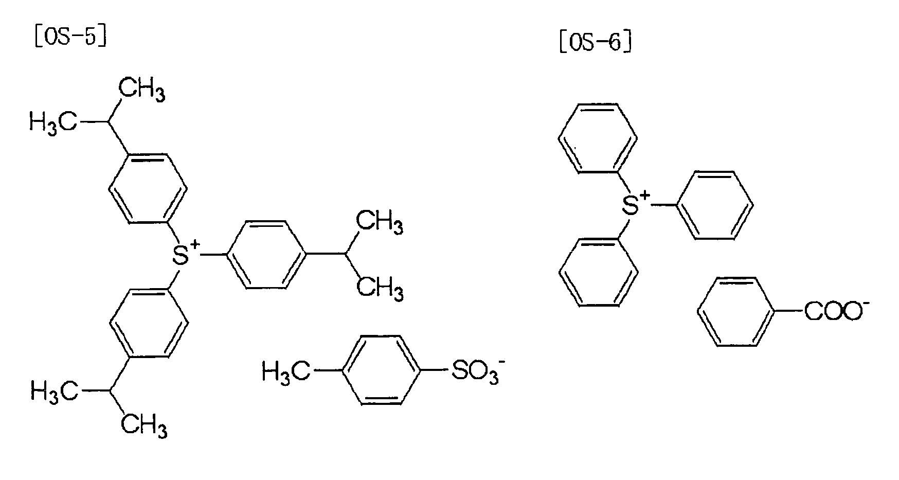


- Other than those described above, specific aromatic sulfonium salts described in
JP-A-2002-148790 JP-A-2002-148790 JP-A-2002-350207 JP-A-2002-6482 - In the present invention, an onium salt except for the above-described sulfonium salt polymerization initiator is also suitably used. Examples of such an onium salt include an iodonium salt and a diazonium salt. Specific examples thereof include onium salts represented by the following formulae (II) and (III):
Formula (II): Ar21―I+―Ar22 Z21-
Formula (III): Ar31-N+≡N Z31-
- In formula (II), Ar21 and Ar22 each independently represents an aryl group having 20 or less carbon atoms, which may have a substituent. When the aryl group has a substituent, preferred examples of the substituent include a halogen atom, a nitro group, an alkyl group having from 12 or less carbon atoms, an alkoxy group having 12 or less carbon atoms, and an aryloxy group having 12 or less carbon atoms. Z21- represents a counter ion having the same meaning as Z11-.
- In formula (III), Ar31 represents an aryl group having 20 or less carbon atoms, which may have a substituent. Preferred examples of the substituent include a halogen atom, a nitro group, an alkyl group having 12 or less carbon atoms, an alkoxy group having 12 or less carbon atoms, an aryloxy group having 12 or less carbon atoms, an alkylamino group having 12 or less carbon atoms, a dialkylamino group having 12 or less carbon atoms, an arylamino group having 12 or less carbon atoms, and a diarylamino group having 12 or less carbon atoms. Z31- represents a counter ion having the same meanings as Z11-.
- Specific examples of the onium salt represented by formula (II) ([OI-1] to [OI-10]) and the onium salt represented by formula (III) ([ON-1] to [ON-5]), which can be suitably used in the present invention, are set forth below, but the present invention is not limited thereto.


- Specific examples of the onium salt which can be suitably used as the polymerization initiator in the present invention include those described in JP-A-2001-133969.
- The polymerization initiator (radical generator) for use in the present invention preferably has a maximum absorption wavelength of 400 nm or less, more preferably 360 nm or less. By specifying the absorption wavelength in this way to the ultraviolet region, the photosensitive lithographic printing plate can be handled under white light.
- The total content of the polymerization initiator in the photosensitive layer is from 0.1 to 50 mass%, preferably from 0.5 to 30 mass%, more preferably from 1 to 20 mass%, based on the entire solid content.
- Furthermore, in the invention, in addition to the foregoing basic components, it is desired to add a small amount of a thermal polymerization inhibitor during the production or storage of the photopolymerizable composition for the purpose of preventing unnecessary thermal polymerization of the polymerizable ethylenically unsaturated bond-containing compound from occurring. Examples of a suitable thermal polymerization inhibitor include hydroquinone, p-methoxyphenol, di-t-butyl-p-cresol, pyrogallol, t-butyl chatecol, benzoquinone, 4,4'-thiobis(3-methyl-6-t-butylphenol), 2,2'-methylenebis(4-methyl-6-t-butylphenol), N-nitrosophenylhydroxylamine cerous salt, and N-nitrosophenylhydroxylamine aluminum salt.
- The amount of addition of the thermal polymerization inhibitor is preferably from about 0.01 % by weight to about 5 % by weight based on the whole of solids constituting the photosensitive layer. Furthermore, if desired, for the purpose of preventing polymerization hindrance due to oxygen, a higher fatty acid derivative such as behenic acid and behenic amide may be added, thereby unevenly distributing it on the surface of the photosensitive layer during a drying step to be carried out after coating. The amount of addition of the higher fatty acid derivative or the like is preferably from about 0.5 % by weight to about 10 % by weight based on the whole of solids constituting the photosensitive layer.
- In addition, for the purpose of coloring the photosensitive layer, a coloring agent may be added. Examples of the coloring agent include pigments (for example, phthalocyanine based pigments (for example, C.I. Pigment Blue 15:3, C.I. Pigment Blue 15:4, and C.I. Pigment Blue 15:6), azo based pigments, carbon black, and titanium oxide) and dyes (for example, Ethyl Violet, Crystal Violet, azo based dyes, anthraquinone based dyes, and cyanine based dyes). The amount of addition of the dye or pigment is preferably from about 0.5 % by weight to about 20 % by weight of the entire composition. In addition, for the purpose of improving physical properties of the cured film, additives such as an inorganic filler and a plasticizer (for example, dioctyl phthalate, dimethyl phthalate, and tricresyl phosphate) may be added. The amount of addition of such an additive is preferably not more than 10 % by weight of the entire composition.
- In coating the photosensitive layer, the foregoing respective components are dissolved in a solvent to form a coating liquid. Examples of the solvent which is used herein include organic solvents such as acetone, methyl ethyl ketone, cyclohexane, ethyl acetate, ethylene dichloride, tetrahydrofuran, toluene, ethylene glycol monomethyl ether, ethylene glycol monoethyl ether, ethylene glycol dimethyl ether, propylene glycol monomethyl ether, propylene glycol monoethyl ether, acetyl acetone, cyclohexanone, diacetone alcohol, ethylene glycol monomethyl ether acetate, ethylene glycol ethyl ether acetate, ethylene glycol monoisopropyl ether, ethylene glycol monobutyl ether acetate, 3-methoxypropanol, methoxymethoxyethanol, diethylene glycol monomethyl ether, diethylene glycol monoethyl ether, diethylene glycol dimethyl ether, diethylene glycol diethyl ether, propylene glycol monomethyl ether acetate, propylene glycol monoethyl ether acetate-3-methoxypropyl acetate, N,N-dimethylformamide, dimethyl sulfoxide, γ-butyrolactone, methyl lactate, and ethyl lactate. Such a solvent can be used singly or in admixture.
- The concentration of solids in the coating liquid is usually from 1 to 50 % by weight.
- Furthermore, for the purpose of enhancing the coating surface quality, it is possible to add a surfactant.
- The coating amount of the photosensitive layer is usually from about 0.1 to about 10 g/m2, preferably from 0.3 to 5 g/m2, and more preferably from 0.5 to 3 g/m2 in terms of weight after drying.
- In order to obtain a lithographic printing plate in the invention, the foregoing photosensitive layer is provided on a support, the surface of which is hydrophilic. As the hydrophilic support, conventionally known hydrophilic supports which are useful in lithographic printing plates can be used without limitations. It is preferable that the support to be used is a dimensionally stable plate-like material. Examples of the support include papers, papers laminated with a plastic (for example, polyethylene, polypropylene, and polystyrene), metal plates (for example, aluminum, zinc, and copper), plastic films (for example, cellulose diacetate, cellulose triacetate, cellulose propionate, cellulose butyrate, cellulose acetate butyrate, cellulose nitrate, polyethylene terephthalate, polyethylene, polystyrene, polypropylene, polycarbonates, and polyvinyl acetal), and papers or plastic films having the foregoing metal laminated or vapor deposited thereon. If desired, the surface of such a support may be subjected to a proper known physical or chemical treatment for the purposes of imparting hydrophilicity, enhancing the strength, and so on.
- In particular, as the preferred support, there are enumerated papers, polyester films, and aluminum plates. Of these, aluminum plates which have good dimensional stability, are relatively cheap and can provide a surface having more excellent hydrophilicity and strength by a surface treatment as the need arises are especially preferable. Furthermore, a composite sheet having an aluminum sheet coupled on a polyethylene terephthalate film as described in
JP-B-48-18327 - The aluminum substrate is a dimensionally stable metal plate containing aluminum as the major component and includes pure aluminum plates and alloy plates containing aluminum as the major component and a slight amount of foreign elements. Plastic films or papers having aluminum (alloy) laminated or vapor deposited thereon are also employable.
- In the foregoing description, the foregoing substrate made of aluminum or an aluminum alloy is named generically as an aluminum substrate and used. Examples of the foreign elements in the alloy include silicon, iron, manganese, copper, magnesium, chromium, zinc, bismuth, nickel, and titanium. The content of the foreign elements in the alloy is not more than 10 % by weight. In the invention, while a pure aluminum plate is suitable, since it is difficult to produce completely pure aluminum according to the smelting technology, a slight amount of foreign elements may be contained.
- With respect to the aluminum plate which is applied in the invention, its composition is not specified, but conventionally known and publicly used raw materials such as JIS A 1050, JIS A 1100, JIS A 3103, and JIS A 3005 can be properly utilized. Furthermore, the thickness of the aluminum substrate which is used in the invention is from about 0.1 mm to 0.6 mm, preferably from 0.15 mm to 0.4 mm, and especially preferably from 0.2 mm to 0.3 mm. This thickness can be properly varied depending upon the size of a printing machine, the size of a printing plate, and the desire of a user. The aluminum substrate may be properly subjected to a substrate surface treatment as described later as the need arises. As a matter of course, the aluminum substrate may not be subjected to a substrate surface treatment.
- The aluminum substrate is usually subjected to a surface roughing treatment. Examples of the surface roughing treatment include mechanical surface roughing, chemical etching, and electrolytic graining as disclosed in
JP-A-56-28893 - The thus surface roughed aluminum substrate may be chemically etched with an acid or an alkali. Examples of an etching agent which is suitably used include sodium hydroxide, sodium carbonate, sodium aluminate, sodium metasilicate, sodium phosphate, potassium hydroxide, and lithium hydroxide. Preferred ranges of the concentration and temperature are from 1 to 50 % and from 20 to 100 °C, respectively. After the etching, for the purpose of removing smuts remaining on the surface, acid washing is carried out. Examples of the acid to be used include nitric acid, sulfuric acid, phosphoric acid, chromic acid, hydrofluoric acid, and borofluoric acid. In particular, as the method for removing smuts after the electrochemical surface roughing treatment, a method for bringing it into contact with sulfuric acid of from 15 to 65 % by weight at a temperature of from 50 to 90 °C as described in
JP-A-53-12739 JP-B-48-28123 - The thus surface roughed aluminum substrate is then subjected to an anodic oxidation treatment to form an oxidized film. For the anodic oxidation treatment, an aqueous solution of sulfuric acid, phosphoric acid, oxalic acid, or boric acid/sodium borate is used singly, or a combination of plural kinds thereof is used as the major component of an electrolytic bath. As a matter of course, the electrolytic liquid may contain components which are usually at least contained in Al alloy plate, electrodes, tap water, ground water, or the like. In addition, a second or third component may be added. Examples of the second or third component as referred to herein include cations such as ions of metals (for example, Na, K, Mg, Li, Ca, Ti, Al, V, Cr, Mn, Fe, Co, Ni, Cu, and Zn) and an ammonium ion; and anions such as a nitric acid ion, a carbonic acid ion, a chlorine ion, a phosphoric acid ion, a fluorine ion, a phosphorous acid ion, a titanium acid ion, a silicic acid ion, and a boric acid ion. The second or third component may be contained in a concentration of from approximately 0 to 10,000 ppm. Though the conditions of the anodic oxidation treatment are not particularly limited, the anodic oxidation treatment is carried out by direct current or alternating current electrolysis in a concentration ranging from 30 to 500 g/liter at a treatment temperature ranging from 10 to 70 °C in a current density ranging from 0.1 to 40 A/m2. The thickness of the formed anodically oxidized film is in the range of from 0.5 to 1.5 µm, and preferably in the range of from 0.5 to 1.0 µm.
- In addition, after carrying out these treatments, a treatment for undercoating a water-soluble resin (for example, polyvinyl phosphonic acid, polymers or copolymers having a sulfonic group in the side chain thereof, and polyacrylic acid), a water-soluble metal salt (for example, zinc borate), a yellow dye, an amine salt, etc. is suitable. Moreover, a sol-gel treated substrate which has been subjected to covalent bonding with a functional group capable of causing addition reaction by a radical as disclosed in JP-A-7-159983 is suitably used.
- As other preferred examples, there can be enumerated ones in which a waterproof hydrophilic layer is provided as a surface layer on an arbitrary support. Examples of such a surface layer include layers comprising an inorganic pigment and a binder as described in U.S. Patent No. 3,055,295 and JP-A-56-13168, hydrophilic swelling layers as described in JP-A-9-80744, and sol-gel films comprising titanium oxide, polyvinyl alcohol, and a silicic acid as described in JP-T-8-507727. Such a hydrophilic treatment is carried out for the purposes of, in addition to making the surface of the support hydrophilic, preventing harmful reaction of the photopolymerizable composition to be provided thereon and enhancing adhesion of the photosensitive layer.
- For the purpose of improving adhesion between the photosensitive layer and the substrate and staining properties, the photosensitive lithographic printing plate in the invention may be provided with an intermediate layer. Specific examples of the such an intermediate layer include ones as described in
JP-B-50-7481 JP-A-54-72104 JP-A-59-101651 JP-A-60-149491 JP-A-60-232998 JP-A-3-56177 JP-A-4-282637 JP-A-5-16558 JP-A-5-246171 JP-A-7-159983 JP-A-7-314937 JP-A-8-202025 JP-A-8-320551 JP-A-9-34104 JP-A-9-236911 JP-A-9-269593 JP-A-10-69092 JP-A-10-115931 JP-A-10-161317 JP-A-10-260536 JP-A-10-282682 JP-A-11-84674 JP-A-11-38635 JP-A-11-38629 JP-A-10-282645 JP-A-10-301262 JP-A-11-24277 JP-A-11-109641 JP-A-10-319600 JP-A-11-327152 JP-A-2000-10292 JP-A-2000-235254 JP-A-2000-352824 JP-A-2001-209170 - In the present invention, an inserting paper is used for preventing the protective layer from being damaged during storage or conveyance of the photosensitive lithographic printing plate.
- Generally, the photosensitive lithographic printing plate is, for example, stored, stocked or transported in the state that an inserting paper is interposed between plate materials so as to prevent mechanical shock during storage or reduce unwanted impact during conveyance, and various inserting papers are known.
- As for the paper material of the inserting paper, wood pulp, synthetic pulp (polyethylene fiber), natural fiber such as hemp, regenerated cellulose and the like may be used.
- In many cases, a low-cost raw material is selected for the inserting paper so as to reduce the material cost. Examples of the inserting paper which can be used include a paper using 100% wood pulp, a paper using a mixture of wood pulp and synthetic pulp, and a paper obtained by providing a low-density or high-density polyethylene layer on the surface of such a paper. Particularly, in the case of a paper not using synthetic pulp or a polyethylene layer, the material cost is low and in turn, the inserting paper can be produced at a low cost.
- More specifically, the inserting paper is preferably a paper produced from a paper material prepared by beating bleached kraft pulp, diluting it to a concentration of 4%, adding a sizing agent and a paper-strengthening agent in an amount of 0.1% and 0.2%, respectively, based on the mass of the base paper, and further adding aluminum sulfate until the pH value reaches 5.0, in which the inserting paper has a basis weight of 20 to 60 g/m2, preferably from 25 to 50 g/m2 (according to the measurement method prescribed in JIS P 8124), and a thickness of 42 to 80 µm, preferably from 45 to 55 µm, more preferably from 40 to 50 µm (according to the measurement method prescribed in JIS P 8118), and satisfies the chemical requirement that no NH3 gas is detected by a NH3 gas detection method of cutting 20 g of a sample into fine pieces, placing the sample in 100 g of pure water and after heating it in a sealed state at 110°C for 10 minutes, measuring a NH3 gas by a Kitagawa gas detecting tube (for 20 ppm) and at the same time, no white turbidity is observed in a chloride detection method of placing 3 ml of an inserting paper sample in 6 ml of distilled water, adding 2 drops of a 1 mass% silver nitrate solution thereto, and observing the presence or absence of white turbidity due to chloride. Among the inserting papers according to this design, preferred is an inserting paper having a basis weight of 30 to 60 g/m2, a smoothness of 10 to 100 seconds as measured by the Bekk smoothness measurement method prescribed in JIS P 8119, a water content of 4 to 8% as measured by the water content measurement method prescribed in JIS P 8127, and a density of 0.7 to 0.9 g/cm3.
- In the present invention, such a known inserting paper may be appropriately selected and used.
- The plate-making method for the photosensitive lithographic printing plate of the present invention is described in detail below. The above-described photosensitive lithographic printing plate is image-exposed and then developed with an aqueous alkali solution. The developer for use in the plate-making method of the present invention is described below.
- Though the developing solution to be used in the plate-making process of the photosensitive lithographic printing plate of the invention is not particularly limited, for example, a developing solution containing an inorganic alkaline salt and a nonionic surfactant and usually having a pH of from 11.0 to 12.5 is suitably used.
- The inorganic alkaline salt can be properly used. Examples thereof include inorganic alkaline agents such as sodium hydroxide, potassium hydroxide, ammonium hydroxide, lithium hydroxide, sodium silicate, potassium silicate, ammonium silicate, lithium silicate, sodium triphosphate, potassium triphosphate, ammonium triphosphate, sodium carbonate, potassium carbonate, ammonium carbonate, sodium hydrogencarbonate, potassium hydrogencarbonate, ammonium hydrogencarbonate, sodium borate, potassium borate, and ammonium borate. These inorganic alkaline agents may be used singly or in combination of two or more kinds thereof.
- In the case where a silicate is used, it is possible to easily adjust developability by regulating a mixing ratio and a concentration of silicon oxide SiO2 as a component of the silicate and an alkaline oxide M2O (wherein M represents an alkali metal or an ammonium group). Among the foregoing alkaline aqueous solutions, ones having a mixing ratio of the foregoing silicon oxide SiO2 and the alkaline oxide M2O (a molar ratio of SiO2/M2O) of from 0.5 to 3.0 are preferable, and ones having the subject mixing ratio of from 1.0 to 2.0 are more preferable. The amount of addition of the foregoing SiO2/M2O mixture is preferably from 1 to 10 % by weight, more preferably from 3 to 8 % by weight, and most preferably from 4 to 7 % by weight based on the weight of the alkaline aqueous solution. When this concentration falls within the foregoing range, the developability and treatment ability are not lowered, the generation of precipitation or the formation of a crystal does not occur, and gelation does not occur during neutralization at the time of discharging a waste liquid so that the treatment of waste liquid is not impaired.
- Furthermore, for the purposes of finely regulating the alkaline concentration and assisting the solubility of the photosensitive layer, an organic alkaline agent may be auxiliarily used jointly. Examples of the organic alkaline agent which can be used jointly include monomethylamine, dimethylamine, trimethylamine, monoethylamine, diethylamine, triethylamine, monoisopropylamine, diisopropylamine, triisopropylamine, n-butylamine, monoethanolamine, diethanolamine, triethanolamine, monoisopropanolamine, diisopropanolamine, ethyleneimine, ethylenediamine, pyridine, and tetramethylammonium hydroxide. These alkaline agents are used singly or in combination of two or more kinds thereof.
- The surfactant can be properly used. Examples thereof include nonionic surfactants such as polyoxyalkylene ether group-containing nonionic surfactants, polyoxyethylene alkyl esters (for example, polyoxyethylene stearate), sorbitan alkyl esters (for example, sorbitan monolaurate, sorbitan monostearate, sorbitan distearate, sorbitan monooleate, sorbitan sesquioleate, and sorbitan trioleate), and monoglyceride alkyl esters (for example, glycerol monostearate and glycerol monooleate); anionic surfactants such as alkylbenzenesulfonic acid salts (for example, sodium dodecylbenzenesulfonate), alkylnaphthalenesulfonic acid salts (for example, sodium butylnaphthalenesulfonate, sodium pentylnaphthalenesulfonate, sodium hexylnaphthalenesulfonate, and sodium octylnaphthalenesulfonate), alkylsulfuric acid salts (for example, sodium laurylsulfate), alkylsulfonic acid salts (for example, sodium dodecylsulfonate), and sulfosuccinic acid ester salts (for example, sodium dilaurylsulfosuccinate); and ampholytic surfactants such as alkyl betaines (for example, lauryl betaine and stearyl betaine) and amino acids. Of these, polyoxyalkylene ether group-containing nonionic surfactants are especially preferable.
- As the polyoxyalkylene ether group-containing nonionic surfactant, ones having a structure represented by the following formula (IV) are suitably used.
R40-O-(R41-O)pH (IV)
- In the foregoing formula (IV), R40 represents an alkyl group having from 3 to 15 carbon atoms, an aromatic hydrocarbon group having from 6 to 15 carbon atoms, or a heteroaromatic ring group having from 4 to 15 carbon atoms (incidentally, examples of the substituent include an alkyl group having from 1 to 20 carbon atoms, a halogen atom (for example, Br, Cl, and I), an aromatic hydrocarbon group having from 6 to 15 carbon atoms, an aralkyl group having from 7 to 17 carbon atoms, an alkoxy group having from 1 to 20 carbon atoms, an alkoxycarbonyl group having from 2 to 20 carbon atoms, and an acyl group having from 2 to 15 carbon atoms); R41 represents an alkylene group having from 1 to 100 carbon atoms; and p represents an integer of from 1 to 100. Incidentally, these respective groups may contain a substituent, and examples of the substituent include an alkyl group having from 1 to 20 carbon atoms and an aromatic hydrocarbon group having from 6 to 15 carbon atoms.
- In the definition of the foregoing formula (IV), specific examples of the "aromatic hydrocarbon group" include a phenyl group, a tolyl group, a naphthyl group, an anthryl group, a biphenyl group, and a phenanthryl group; and specific examples of the "heteroaromatic ring group" include a furyl group, a thienyl group, an oxazolyl group, an imidazolyl group, a pyranyl group, a pyridinyl group, an acridinyl group, a benzofuranyl group, a benzothienyl group, a benzopyranyl group, a benzoxazolyl group, and a benzimidazolyl group.
- Furthermore, the (R41-O)p moiety of the formula (IV) may be a combination of two or three kinds of groups so far as it falls within the foregoing range. Specifically, there are enumerated random or block-like forms of a combination, for example, a combination of an ethyleneoxy group and a propyleneoxy group, a combination of an ethyleneoxy group and an isopropyloxy group, a combination of an ethyleneoxy group and a butyleneoxy group, and a combination of an ethyleneoxy group and an isobutylene group. In the invention, the polyoxyalkylene ether group-containing surfactant is used singly or in a composite system. It is effective to add the polyoxyalkylene ether group-containing surfactant in an amount of from 1 to 30 % by weight, and preferably from 2 to 20 % by weight in the developing solution. When the addition amount is too low, the developability may be possibly lowered, while it is too high, damage of the development is so strong that printing resistance of a printing plate may be possibly lowered.
- Furthermore, examples of the polyoxyalkylene ether group-containing nonionic surfactant represented by the foregoing formula (IV) include polyoxyethylene alkyl ethers (for example, polyoxyethylene lauryl ether, polyoxyethylene cetyl ether, and polyoxyethylene stearyl ether), polyoxyethylene aryl ethers (for example, polyoxyethylene phenyl ether and polyoxyethylene naphthyl ether), and polyoxyethylene alkylaryl ethers (for example, polyoxyethylene methylphenyl ether, polyoxyethylene octylphenyl ether, and polyoxyethylene nonylphenyl ether).
- Such a surfactant can be used singly or in combination. Furthermore, the content of such a surfactant in the developing solution is suitably in the range of from 0.1 to 20 % by weight as reduced into an active ingredient.
- The pH of the developing solution which is used in the plate-making process of the invention is usually from 11.0 to 12.7, and preferably from 11.5 to 12.5 in view of the image formation and development damage in the exposed area.
- Furthermore, it is preferable that the developing solution which is used in the invention has a conductivity of from 3 to 30 mS/cm. When the conductivity is lower than the foregoing range, in general, elution of the photopolymerizable composition on the surface of the aluminum plate support becomes difficult, thereby causing staining during printing. On the other hand, when the conductivity exceeds the foregoing range, since the salt concentration is high, an elution rate of the photosensitive layer becomes extremely low so that a residual film may be possibly generated in an unexposed area. The conductivity is especially preferably in the range of from 5 to 20 mS/cm.
- By image exposing the photosensitive lithographic printing plate in the invention by conventionally known active rays such as a carbon arc lamp, a high pressure mercury vapor lamp, a xenon lamp, a metal halide lamp, a fluorescent lamp, a tungsten lamp, a halogen lamp, a helium-cadmium laser, an argon ion laser, an FD · YAG laser, a helium-neon laser, and a semiconductor laser (from 350 nm to 600 nm) and then developing it, it is possible to form an image on the surface of the aluminum plate support.
- For the purpose of enhancing a rate of curing of the photosensitive layer, a heating process to be carried out at a temperature of from 50 °C to 140 °C for a period of time of from 1 second to 5 minutes may be provided and carried out after the image exposure but before the development. When the heating temperature falls within the foregoing range, an effect for increasing the rate of curing is brought, and a residual film due to dark polymerization in an unexposed area is not generated.
- Furthermore, as described previously, the protective layer is provided on the photosensitive layer of the photosensitive lithographic printing plate in the invention. There is known a method for achieving the removal of the protective layer and the removal of the unexposed area of the photosensitive layer at the same time by using a developing solution, or a method for removing the protective layer with water or warm water and then removing the photosensitive layer in the unexposed area with a developing solution. An antiseptic, etc. as described in
JP-A-10-10754 JP-A-8-278636 - The development of the photosensitive lithographic printing plate in the invention with the foregoing developing solution is carried out according to a usual method at a temperature of from about 0 to 60 °C, and preferably from about 15 to 40 °C by, for example, dipping the exposed photosensitive lithographic printing plate in the developing solution and rubbing it by a brush or other means.
- In addition, in the case where the development treatment is carried out by using an automatic processor, since the developing solution fatigues corresponding to the amount of treatment, treatment ability may be recovered by using a replenisher or a fresh developing solution. The thus developed photosensitive lithographic printing plate is subjected to post treatments with washing water, a rinse liquid containing a surfactant, etc., and a desensitizing liquid containing gum arabic, a starch derivative, etc. as described in
JP-A-54-8002 JP-A-55-115045 JP-A-59-58431 - In the printing plate as obtained by the foregoing treatments, its printing resistance can be enhanced by a post exposure treatment or a heating treatment such as burning as described in
JP-A-2000-89478 - The lithographic printing plate as obtained by these treatments is set in an offset printing machine and provided for printing of a number of sheets.
- The invention will be hereunder described in detail with reference to the following Examples, but as a matter of course, it should not be construed that the invention is limited thereto.
- An aluminum plate having a thickness of 0.3 mm was etched by dipping in 10 % by weight sodium hydroxide at 60 °C for 25 seconds, washed with running water, neutralized and washed with 20 % by weight nitric acid, and then washed with water.
- This aluminum plate was subjected to an electrolytic surface roughing treatment in a quantity of electricity at the time of anode of 300 coulombs/dm2 in a 1 % by weight nitric acid aqueous solution using an alternating waveform current of sine wave. Subsequently, the resulting aluminum plate was dipped in a 1 % by weight sodium hydroxide aqueous solution at 40 °C for 5 seconds; dipped in a 30 % by weight sulfuric acid aqueous solution; subjected to a desmutting treatment at 60 °C for 40 seconds; and then subjected to an anodic oxidation treatment in a 20 % by weight sulfuric acid aqueous solution for 2 minutes in a current density of 2 A/dm2 such that the anodically oxidized film had a thickness of 2.7 g/m2. A surface roughness thereof was measured and found to be 0.3 µm (in terms of an Ra expression according to JIS B0601).
- On the thus treated aluminum plate, the following intermediate layer liquid was first coated using a bar coater and then dried at 80 °C for 20 seconds. A coating weight of the intermediate layer after drying was 10 mg/m2.
-
- Sol liquid as described below: 100 g
- Methanol: 900 g
-
- • PHOSMER PE (manufactured by Uni-Chemical Co., Ltd.): 5 g
- • Methanol: 45 g
- • Water: 10 g
- • 85 % phosphoric acid: 5 g
- • Tetraethoxysilane: 20 g
- • 3-Methacryloxypropyltrimethoxysilane: 15 g
- A highly sensitive photopolymerizable composition P-1 having the following composition was coated on this intermediate layer in a dry coating weight of 1.4 g/m2 and dried at 100 °C for one minute to form a photosensitive layer.
-
Ethylenically unsaturated bond-containing compound (A1): 4.2 parts by weight Linear organic high molecular polymer (polymer binder) (B 1): 3.6 parts by weight Sensitizer (C1): 0.21 parts by weight Photopolymerization initiator (D1): 0.81 parts by weight Chain transfer agent (E1): 0.3 parts by weight ε-Phthalocyanine dispersion: 0.76 parts by weight Fluorine based nonionic surfactant, MEGAFAC F780 (manufactured by Dainippon Ink and Chemicals, Incorporated) 0.05 parts by weight Methyl ethyl ketone: 58 parts by weight Propylene glycol monomethyl ether acetate: 53 parts by weight 


- Coating solutions for the upper layer, intermediate layer and lower layer were each prepared by mixing 98 mass% of a composition shown in Table 1 and 2 mass% of Surfactant EMALEX 710 (surfactant, produced by Nihon Emulsion Co., Ltd.) and sequentially coated on the photosensitive layer to have a dry coated mass value shown in Table 1 of each layer, thereby forming a protective layer. In this way, Negative Photosensitive Lithographic Printing Plate [P] was obtained. The drying conditions were 120°C and 1 minute.
Table 1: Composition of Protective Layer (unit in column of material: mass%) Upper Layer composition T1 T2 T3 T4 T5 T6 T7 Coated amount (g/m2) 0.5 0.5 0.5 0.5 0.5 0.5 0.5 PVA-105 98 85 85 85 85 PVA-205 13 SOMASIF ME-100 13 MERPOL MF-25 13 98 PAOGEN EP-25 13 98 Intermediate layer composition M1 M2 M3 Coated amount (g/m2) 1.8 1.8 1.8 PVA-105 98 85 PVA-205 98 PVP K30 13 Lower layer composition B1 B2 B3 B4 B5 B6 B7 Coated amount (g/m2) 0.5 0.5 0.5 0.5 0.5 0.5 0.5 PVA-105 98 85 85 85 85 PVA-205 13 SOMASIF ME-100 13 MERPOL MF-25 13 98 PAOGEN EP-25 13 98 Comparative protective layer composition R1 R2 R3 Coated amount (g/m2) 2.5 2.5 2.5 PVA-105 98 85 PVA-205 98 PVP K30 13 - PVA-105:
- produced by Kuraray Co., Ltd. (saponification degree: 98 mol%, polymerization degree: 500)
- PVA-205:
- produced by Kuraray Co., Ltd. (saponification degree: 88 mol%, polymerization degree: 500)
- PVA-405:
- produced by Kuraray Co., Ltd. (saponification degree: 81 mol%, polymerization degree: 500)
- PVP K30:
- polyvinylpyrrolidone; produced by Wako Pure Chemical Industries, Ltd.
- Luvitec VA64W:
- vinylpyrrolidone-vinyl acetate copolymer, produced by ICP
- SOMASIF ME-100:
- produced by CO-OP Chemical Co., Ltd., aspect ratio: 1,000 or more
- MERPOL MF-25:
- water-soluble polymer, produced by Daiichi Kogyo Kagaku K.K.
- PAOGEN EP-25:
- water-soluble polymer, produced by Daiichi Kogyo Kagaku K.K.
- A paper material was prepared by beating bleached kraft pulp and diluting it to a concentration of 4 mass% and after adding aluminum sulfate thereto until the pH value became 5.0, subjected to papermaking to produce an inserting paper for photosensitive printing plate, having a basis weight of 35 g/m2.
- The obtained photosensitive lithographic printing plate was subjected to imagewise drawing on Vx9600CTP (light source wavelength: 405 nm) manufactured by Fuji Photo Film Co., Ltd. under the control of adjusting the exposure amount on the photosensitive material to 0.05 mJ/cm2, then developed by using PS Processor IP850HD (manufactured by G & J) into which an alkali developer having the following composition was charged, for a development time of 28 seconds while keeping the liquid temperature to 25°C, and further subjected to printing in Lithrone (printing press, manufactured by Komori Corp.) by using DIC-GEOS(N) (black ink, produced by DaiNippon Ink & Chemicals, Inc.). The press life was evaluated by the number of sheets printed until it was recognized with an eye that the density of a solid image started thinning. The evaluation results are shown in Table 2.
-
Potassium hydroxide 0.15 g Polyoxyethylene naphthyl ether (n=13) 5.0 g Chelest 400 (chelating agent) 0.1 g Water 94.75 g - An inserting paper was laminated on the obtained Negative Photosensitive Lithographic Printing Plate [P] to produce a laminated product.
- The dynamic friction coefficient between the protective layer surface of Negative Photosensitive Lithographic Printing Plate [P] and the inserting paper was measured according to the method prescribed in JIS P 8147, and the results are shown in Table 2.
- The laminated product comprising a negative photosensitive lithographic printing plate and an inserting paper produced above was set in a cassette, and 500 plates were conveyed by an autoloader from the setting portion to the exposure part and then to the development part. How many plates were not normally processed (jamming) was evaluated. The evaluation results are shown in Table 2.
- The laminated product of Negative Photosensitive Lithographic Printing Plate [P] produced was set in a cassette and conveyed by an autoloader from the setting portion to the exposure part and then to the development part, and development was performed by the above-described automatic developing machine. The state of scratches generated in this process was evaluated. The evaluation was performed according to the following criteria. The exposure and development conditions were as described above. Also, in the evaluation of scratch resistance, the presence or absence of a white spotted state was inspected, because when the photosensitive material surface is scratched before development, an image is not formed in this portion at the development and the image area provides a white spotted state.
- The evaluation results are shown in Table 2.
- ○ : Scratches were not observed.
- Δ : Scratches were faintly observed.
- × : Scratches were clearly observed.
- The lithographic printing plate developed and used for the evaluation of scratch resistance above was subjected to printing in a printing press, SOR-M, manufactured by Heilderberg Co., by using a commercially available oily ink. At this time, whether staining was generated or not in the non-image area was observed with an eye and used as an index for scumming resistance. The exposure and development conditions were as described above. The evaluation results are shown in Table 2.
- ○ : Staining was not observed.
- Δ : Staining was faintly observed.
- × : Staining was clearly observed.
- On the surface of a photographic paper having a thickness of about 200 µm, where polyethylene was coated to a thickness of about 20 µm on both surfaces, the protective layer described above was coated under the same conditions as above and dried to produce a sample for measurement. The oxygen permeability of the photographic paper measured previously under the following measurement conditions was about 700 [cm3/(m2·day)], and this was a sufficiently negligible value at the measurement of permeability in the protective layer.
- Using the thus-obtained sample, the oxygen permeability [cm3/(m2·day)] was measured under the conditions of 25°C and 60% RH according to the gas permeability test method prescribed in JIS K7126B and ASTM D3985 by using OX-TRAN2/20 manufactured by Mocon. The evaluation results are shown in Table 2.
- A universal tensile tester, Tensilon (manufactured by Baldwin Co., Ltd.), was used. In the measurement, a pressure-sensitive adhesive tape (width: 20 cm) was attached on the protective layer of the unexposed plate material, and the protective layer with the tape was peeled off from the photosensitive layer by the universal tensile tester, Tensilon, at a rate of 40 mm/min. The peeling force (g) required for the separation was measured.
- The halftone dot area was measured in the same manner except for using a photosensitive lithographic printing plate which was hermetically packaged together with the inserting paper by an aluminum kraft paper and left standing at 60°C for 3 days. As for the halftone dot area, the area of 30 to 70% halftone dot was measured by using a reflection densitometer, Gretag D19C (manufactured by Gretag-Macbeth), in the halftone dot area ratio mode and the cyan mode of the reflection densitometer. Thereafter, the difference between the halftone dot area with standing at 60°C for 3 days and the halftone dot area without standing at 60°C for 3 days was calculated, and the dot fluctuation (Δ%) due to enforced aging was determined. As the absolute value of the numeral obtained is smaller, the effect by the enforced aging is smaller, that is, the storage safety is higher. The evaluation results are shown in Table 2.

- The procedure until the formation of photosensitive layer was performed in the same manner as in Example 1 except for chaining Polymer Binder B1 of Photopolymerizable Composition P-1 to B2, and then the protective layer shown in Table 3 was provided to produce photosensitive lithographic printing plates of Examples 11 to 13 and Comparative Example 4. The photosensitive lithographic printing plates obtained were evaluated. The evaluation results are shown in Table 3.

Table 3: Examples 11 to 13 and Comparative Example 4 Example Comparative Example 11 12 20 4 Protective Layer Upper layer T2 T2 T4 R1 Intermediate layer M3 M2 M2 Lower layer none none none Dynamic friction coefficient 0.55 0.55 0.35 0.75 Oxygen permeability (cm3/cm2·day) 3.2 3.1 2.9 0.1 Adhesive force between photosensitive layer and protective layer (g/cm) 28 41 45 13 Conveyability (plates) 0 0 1 29 Scratch resistance ○ ○ ○ Δ Scumming resistance Δ Δ Δ × Press life (sheets in ten thousand) 16 18 18 18 Dot fluctuation in enforced aging (%) 1 0 0 fogged - As apparent from Tables 2 and 3, in all of the lithographic printing plates of the present invention, the conveyability and scratch resistance are excellent, the storage stability is also good, a high-quality image free of staining in the non-image area is formed, and high press life is maintained even under the high-sensitivity condition that the exposure amount is 0.05 mJ/cm2. On the other hand, in all of the lithographic printing plates of Comparative Examples having an excessively high dynamic friction coefficient, the conveyability and scratch resistance are inferior and staining is generated in the non-image area.
- Also, in the photosensitive lithographic printing plates of Examples where the oxygen permeability A of the protective layer is in the range of 1.0≤A≤20 (cm3/m2 · day), satisfactory results are obtained in view of both the press life and the storage stability.
- This application is based on
Japanese Patent application JP 2005-84081, filed March 23, 2005
Claims (8)
- A photosensitive lithographic printing plate comprising: a hydrophilic support; a photosensitive layer; and a protective layer in this order, wherein the photosensitive layer contains a compound having an ethylenically unsaturated double bond and a polymer binder, and the protective layer includes at least two layers each containing water-soluble resin.
- The photosensitive lithographic printing plate as claimed in claim 1, wherein at least one of the layers included in the protective layer has an oxygen permeability at 25°C under 1 atm of from 1.0 to 20 cm3/m2·day, and a dynamic friction coefficient between an outermost surface of the protective layer and an inserting paper or back surface of the photosensitive lithographic printing plate is from 0.2 to 0.7.
- The photosensitive lithographic printing plate as claimed in claim 2, wherein the dynamic friction coefficient between an outermost surface of the protective layer and an inserting paper or back surface of the photosensitive lithographic printing plate is from 0.3 to 0.6.
- The photosensitive lithographic printing plate as claimed in any one of claims 1 to 3, wherein at least one of the layers included in the protective layer contains a polyvinyl alcohol.
- The photosensitive lithographic printing plate as claimed in any one of claims 1 to 3, wherein at least one of the layers included in the protective layer contains polyester or polyurethane.
- The photosensitive lithographic printing plate as claimed in any one of claim 4, wherein at least one of the layers included in the protective layer contains polyester or polyurethane, and the at least one layer containing polyester or polyurethane is other layer than the at least one layer containing a polyvinyl alcohol.
- The photosensitive lithographic printing plate as claimed in any one of claims 1 to 6, wherein the polymer binder is a polyurethane resin having a crosslinking group in a side chain or a (meth)acrylic resin having a crosslinking group in a side chain.
- The photosensitive lithographic printing plate as claimed in any one of claims 1 to 6, wherein the polymer binder is a polyurethane resin having a crosslinking group in a side chain.
Applications Claiming Priority (1)
| Application Number | Priority Date | Filing Date | Title |
|---|---|---|---|
| JP2005084081A JP4425168B2 (en) | 2005-03-23 | 2005-03-23 | Photosensitive planographic printing plate |
Publications (2)
| Publication Number | Publication Date |
|---|---|
| EP1720065A1 true EP1720065A1 (en) | 2006-11-08 |
| EP1720065B1 EP1720065B1 (en) | 2017-06-14 |
Family
ID=36848379
Family Applications (1)
| Application Number | Title | Priority Date | Filing Date |
|---|---|---|---|
| EP06005825.2A Expired - Lifetime EP1720065B1 (en) | 2005-03-23 | 2006-03-22 | Photosensitive lithographic printing plate |
Country Status (2)
| Country | Link |
|---|---|
| EP (1) | EP1720065B1 (en) |
| JP (1) | JP4425168B2 (en) |
Cited By (1)
| Publication number | Priority date | Publication date | Assignee | Title |
|---|---|---|---|---|
| US8318405B2 (en) | 2009-03-13 | 2012-11-27 | Eastman Kodak Company | Negative-working imageable elements with overcoat |
Citations (5)
| Publication number | Priority date | Publication date | Assignee | Title |
|---|---|---|---|---|
| EP0819987A1 (en) * | 1996-07-19 | 1998-01-21 | Toyo Boseki Kabushiki Kaisha | Photosensitive resin laminate, production method thereof and package thereof |
| JP2004125876A (en) * | 2002-09-30 | 2004-04-22 | Fuji Photo Film Co Ltd | Photopolymerizable planographic printing plate |
| EP1450207A1 (en) * | 2003-02-20 | 2004-08-25 | Fuji Photo Film Co., Ltd. | Planographic printing plate precursor |
| JP2004361720A (en) * | 2003-06-05 | 2004-12-24 | Fuji Photo Film Co Ltd | Lithographic printing plate and its manufacturing method |
| US20050005794A1 (en) * | 2003-06-05 | 2005-01-13 | Fuji Photo Film Co., Ltd. | Coating method and planographic printing plate |
-
2005
- 2005-03-23 JP JP2005084081A patent/JP4425168B2/en not_active Expired - Fee Related
-
2006
- 2006-03-22 EP EP06005825.2A patent/EP1720065B1/en not_active Expired - Lifetime
Patent Citations (5)
| Publication number | Priority date | Publication date | Assignee | Title |
|---|---|---|---|---|
| EP0819987A1 (en) * | 1996-07-19 | 1998-01-21 | Toyo Boseki Kabushiki Kaisha | Photosensitive resin laminate, production method thereof and package thereof |
| JP2004125876A (en) * | 2002-09-30 | 2004-04-22 | Fuji Photo Film Co Ltd | Photopolymerizable planographic printing plate |
| EP1450207A1 (en) * | 2003-02-20 | 2004-08-25 | Fuji Photo Film Co., Ltd. | Planographic printing plate precursor |
| JP2004361720A (en) * | 2003-06-05 | 2004-12-24 | Fuji Photo Film Co Ltd | Lithographic printing plate and its manufacturing method |
| US20050005794A1 (en) * | 2003-06-05 | 2005-01-13 | Fuji Photo Film Co., Ltd. | Coating method and planographic printing plate |
Cited By (1)
| Publication number | Priority date | Publication date | Assignee | Title |
|---|---|---|---|---|
| US8318405B2 (en) | 2009-03-13 | 2012-11-27 | Eastman Kodak Company | Negative-working imageable elements with overcoat |
Also Published As
| Publication number | Publication date |
|---|---|
| JP4425168B2 (en) | 2010-03-03 |
| EP1720065B1 (en) | 2017-06-14 |
| JP2006267422A (en) | 2006-10-05 |
Similar Documents
| Publication | Publication Date | Title |
|---|---|---|
| EP1195646B1 (en) | Photosensitive lithographic printing plate precursor | |
| EP1736826B1 (en) | Photosensitive lithographic printing plate | |
| EP2725422A1 (en) | Photosensitive composition, master plate for planographic printing plate, polyurethane, and method for producing polyurethane | |
| JP2007199647A (en) | Polymerizable composition and planographic printing plate precursor using the same | |
| EP1685958B1 (en) | Lithographic printing plate precursor and polymerizable composition | |
| JP2008249851A (en) | Planographic printing plate precursor | |
| US20050031986A1 (en) | Radical polymerizable composition and lithographic printing plate precursor using the same | |
| JP2006085049A (en) | Negative image forming material | |
| JP2007272134A (en) | Negative lithographic printing original plate | |
| JP4864789B2 (en) | Planographic printing plate precursor and laminate of planographic printing plate precursor | |
| EP1739486B1 (en) | Photosensitive lithographic printing plate | |
| EP1720065B1 (en) | Photosensitive lithographic printing plate | |
| EP1757984B1 (en) | Photosensitive lithographic printing plate | |
| EP1562078A2 (en) | Polymerizable lithographic printing plate precursor | |
| JP2006225432A (en) | Alkali-soluble polyurethane resin, polymerizable composition and lithographic printing original plate | |
| JP4512538B2 (en) | Photosensitive planographic printing plate | |
| JP2007114738A (en) | Photosensitive planographic printing plate | |
| JP4425124B2 (en) | Photosensitive lithographic printing plate laminate | |
| JP2005048143A (en) | Polymerizable composition | |
| JP4411168B2 (en) | Photosensitive planographic printing plate | |
| JP4368323B2 (en) | Photosensitive planographic printing plate | |
| JP4593390B2 (en) | Negative image forming material | |
| JP2009053632A (en) | Polymerizable composition, lithographic printing plate precursor and alkali-soluble resin | |
| JP2008249841A (en) | Photosensitive planographic printing plate | |
| JP2007272133A (en) | Planographic printing plate precursor and lithographic printing plate precursor laminate |
Legal Events
| Date | Code | Title | Description |
|---|---|---|---|
| PUAI | Public reference made under article 153(3) epc to a published international application that has entered the european phase |
Free format text: ORIGINAL CODE: 0009012 |
|
| AK | Designated contracting states |
Kind code of ref document: A1 Designated state(s): AT BE BG CH CY CZ DE DK EE ES FI FR GB GR HU IE IS IT LI LT LU LV MC NL PL PT RO SE SI SK TR |
|
| AX | Request for extension of the european patent |
Extension state: AL BA HR MK YU |
|
| RAP1 | Party data changed (applicant data changed or rights of an application transferred) |
Owner name: FUJIFILM CORPORATION |
|
| 17P | Request for examination filed |
Effective date: 20070507 |
|
| AKX | Designation fees paid |
Designated state(s): AT BE BG CH CY CZ DE DK EE ES FI FR GB GR HU IE IS IT LI LT LU LV MC NL PL PT RO SE SI SK TR |
|
| 17Q | First examination report despatched |
Effective date: 20160714 |
|
| GRAP | Despatch of communication of intention to grant a patent |
Free format text: ORIGINAL CODE: EPIDOSNIGR1 |
|
| INTG | Intention to grant announced |
Effective date: 20170217 |
|
| GRAS | Grant fee paid |
Free format text: ORIGINAL CODE: EPIDOSNIGR3 |
|
| GRAA | (expected) grant |
Free format text: ORIGINAL CODE: 0009210 |
|
| AK | Designated contracting states |
Kind code of ref document: B1 Designated state(s): AT BE BG CH CY CZ DE DK EE ES FI FR GB GR HU IE IS IT LI LT LU LV MC NL PL PT RO SE SI SK TR |
|
| REG | Reference to a national code |
Ref country code: GB Ref legal event code: FG4D |
|
| REG | Reference to a national code |
Ref country code: CH Ref legal event code: EP Ref country code: AT Ref legal event code: REF Ref document number: 901520 Country of ref document: AT Kind code of ref document: T Effective date: 20170615 |
|
| REG | Reference to a national code |
Ref country code: IE Ref legal event code: FG4D |
|
| REG | Reference to a national code |
Ref country code: DE Ref legal event code: R096 Ref document number: 602006052766 Country of ref document: DE |
|
| REG | Reference to a national code |
Ref country code: NL Ref legal event code: MP Effective date: 20170614 |
|
| REG | Reference to a national code |
Ref country code: LT Ref legal event code: MG4D |
|
| PG25 | Lapsed in a contracting state [announced via postgrant information from national office to epo] |
Ref country code: GR Free format text: LAPSE BECAUSE OF FAILURE TO SUBMIT A TRANSLATION OF THE DESCRIPTION OR TO PAY THE FEE WITHIN THE PRESCRIBED TIME-LIMIT Effective date: 20170915 Ref country code: ES Free format text: LAPSE BECAUSE OF FAILURE TO SUBMIT A TRANSLATION OF THE DESCRIPTION OR TO PAY THE FEE WITHIN THE PRESCRIBED TIME-LIMIT Effective date: 20170614 Ref country code: LT Free format text: LAPSE BECAUSE OF FAILURE TO SUBMIT A TRANSLATION OF THE DESCRIPTION OR TO PAY THE FEE WITHIN THE PRESCRIBED TIME-LIMIT Effective date: 20170614 Ref country code: FI Free format text: LAPSE BECAUSE OF FAILURE TO SUBMIT A TRANSLATION OF THE DESCRIPTION OR TO PAY THE FEE WITHIN THE PRESCRIBED TIME-LIMIT Effective date: 20170614 |
|
| REG | Reference to a national code |
Ref country code: AT Ref legal event code: MK05 Ref document number: 901520 Country of ref document: AT Kind code of ref document: T Effective date: 20170614 |
|
| PG25 | Lapsed in a contracting state [announced via postgrant information from national office to epo] |
Ref country code: LV Free format text: LAPSE BECAUSE OF FAILURE TO SUBMIT A TRANSLATION OF THE DESCRIPTION OR TO PAY THE FEE WITHIN THE PRESCRIBED TIME-LIMIT Effective date: 20170614 Ref country code: NL Free format text: LAPSE BECAUSE OF FAILURE TO SUBMIT A TRANSLATION OF THE DESCRIPTION OR TO PAY THE FEE WITHIN THE PRESCRIBED TIME-LIMIT Effective date: 20170614 Ref country code: SE Free format text: LAPSE BECAUSE OF FAILURE TO SUBMIT A TRANSLATION OF THE DESCRIPTION OR TO PAY THE FEE WITHIN THE PRESCRIBED TIME-LIMIT Effective date: 20170614 Ref country code: BG Free format text: LAPSE BECAUSE OF FAILURE TO SUBMIT A TRANSLATION OF THE DESCRIPTION OR TO PAY THE FEE WITHIN THE PRESCRIBED TIME-LIMIT Effective date: 20170914 |
|
| PG25 | Lapsed in a contracting state [announced via postgrant information from national office to epo] |
Ref country code: EE Free format text: LAPSE BECAUSE OF FAILURE TO SUBMIT A TRANSLATION OF THE DESCRIPTION OR TO PAY THE FEE WITHIN THE PRESCRIBED TIME-LIMIT Effective date: 20170614 Ref country code: RO Free format text: LAPSE BECAUSE OF FAILURE TO SUBMIT A TRANSLATION OF THE DESCRIPTION OR TO PAY THE FEE WITHIN THE PRESCRIBED TIME-LIMIT Effective date: 20170614 Ref country code: AT Free format text: LAPSE BECAUSE OF FAILURE TO SUBMIT A TRANSLATION OF THE DESCRIPTION OR TO PAY THE FEE WITHIN THE PRESCRIBED TIME-LIMIT Effective date: 20170614 Ref country code: SK Free format text: LAPSE BECAUSE OF FAILURE TO SUBMIT A TRANSLATION OF THE DESCRIPTION OR TO PAY THE FEE WITHIN THE PRESCRIBED TIME-LIMIT Effective date: 20170614 Ref country code: CZ Free format text: LAPSE BECAUSE OF FAILURE TO SUBMIT A TRANSLATION OF THE DESCRIPTION OR TO PAY THE FEE WITHIN THE PRESCRIBED TIME-LIMIT Effective date: 20170614 |
|
| PG25 | Lapsed in a contracting state [announced via postgrant information from national office to epo] |
Ref country code: PL Free format text: LAPSE BECAUSE OF FAILURE TO SUBMIT A TRANSLATION OF THE DESCRIPTION OR TO PAY THE FEE WITHIN THE PRESCRIBED TIME-LIMIT Effective date: 20170614 Ref country code: IT Free format text: LAPSE BECAUSE OF FAILURE TO SUBMIT A TRANSLATION OF THE DESCRIPTION OR TO PAY THE FEE WITHIN THE PRESCRIBED TIME-LIMIT Effective date: 20170614 Ref country code: IS Free format text: LAPSE BECAUSE OF FAILURE TO SUBMIT A TRANSLATION OF THE DESCRIPTION OR TO PAY THE FEE WITHIN THE PRESCRIBED TIME-LIMIT Effective date: 20171014 |
|
| REG | Reference to a national code |
Ref country code: DE Ref legal event code: R097 Ref document number: 602006052766 Country of ref document: DE |
|
| PLBE | No opposition filed within time limit |
Free format text: ORIGINAL CODE: 0009261 |
|
| STAA | Information on the status of an ep patent application or granted ep patent |
Free format text: STATUS: NO OPPOSITION FILED WITHIN TIME LIMIT |
|
| PG25 | Lapsed in a contracting state [announced via postgrant information from national office to epo] |
Ref country code: DK Free format text: LAPSE BECAUSE OF FAILURE TO SUBMIT A TRANSLATION OF THE DESCRIPTION OR TO PAY THE FEE WITHIN THE PRESCRIBED TIME-LIMIT Effective date: 20170614 |
|
| 26N | No opposition filed |
Effective date: 20180315 |
|
| PG25 | Lapsed in a contracting state [announced via postgrant information from national office to epo] |
Ref country code: SI Free format text: LAPSE BECAUSE OF FAILURE TO SUBMIT A TRANSLATION OF THE DESCRIPTION OR TO PAY THE FEE WITHIN THE PRESCRIBED TIME-LIMIT Effective date: 20170614 |
|
| REG | Reference to a national code |
Ref country code: CH Ref legal event code: PL |
|
| PG25 | Lapsed in a contracting state [announced via postgrant information from national office to epo] |
Ref country code: MC Free format text: LAPSE BECAUSE OF FAILURE TO SUBMIT A TRANSLATION OF THE DESCRIPTION OR TO PAY THE FEE WITHIN THE PRESCRIBED TIME-LIMIT Effective date: 20170614 |
|
| REG | Reference to a national code |
Ref country code: BE Ref legal event code: MM Effective date: 20180331 |
|
| REG | Reference to a national code |
Ref country code: IE Ref legal event code: MM4A |
|
| PG25 | Lapsed in a contracting state [announced via postgrant information from national office to epo] |
Ref country code: LU Free format text: LAPSE BECAUSE OF NON-PAYMENT OF DUE FEES Effective date: 20180322 |
|
| PG25 | Lapsed in a contracting state [announced via postgrant information from national office to epo] |
Ref country code: IE Free format text: LAPSE BECAUSE OF NON-PAYMENT OF DUE FEES Effective date: 20180322 |
|
| PG25 | Lapsed in a contracting state [announced via postgrant information from national office to epo] |
Ref country code: CH Free format text: LAPSE BECAUSE OF NON-PAYMENT OF DUE FEES Effective date: 20180331 Ref country code: BE Free format text: LAPSE BECAUSE OF NON-PAYMENT OF DUE FEES Effective date: 20180331 Ref country code: LI Free format text: LAPSE BECAUSE OF NON-PAYMENT OF DUE FEES Effective date: 20180331 |
|
| PG25 | Lapsed in a contracting state [announced via postgrant information from national office to epo] |
Ref country code: FR Free format text: LAPSE BECAUSE OF NON-PAYMENT OF DUE FEES Effective date: 20180331 |
|
| PGFP | Annual fee paid to national office [announced via postgrant information from national office to epo] |
Ref country code: GB Payment date: 20190320 Year of fee payment: 14 Ref country code: DE Payment date: 20190312 Year of fee payment: 14 |
|
| PG25 | Lapsed in a contracting state [announced via postgrant information from national office to epo] |
Ref country code: TR Free format text: LAPSE BECAUSE OF FAILURE TO SUBMIT A TRANSLATION OF THE DESCRIPTION OR TO PAY THE FEE WITHIN THE PRESCRIBED TIME-LIMIT Effective date: 20170614 |
|
| PG25 | Lapsed in a contracting state [announced via postgrant information from national office to epo] |
Ref country code: HU Free format text: LAPSE BECAUSE OF FAILURE TO SUBMIT A TRANSLATION OF THE DESCRIPTION OR TO PAY THE FEE WITHIN THE PRESCRIBED TIME-LIMIT; INVALID AB INITIO Effective date: 20060322 Ref country code: PT Free format text: LAPSE BECAUSE OF FAILURE TO SUBMIT A TRANSLATION OF THE DESCRIPTION OR TO PAY THE FEE WITHIN THE PRESCRIBED TIME-LIMIT Effective date: 20170614 |
|
| PG25 | Lapsed in a contracting state [announced via postgrant information from national office to epo] |
Ref country code: CY Free format text: LAPSE BECAUSE OF FAILURE TO SUBMIT A TRANSLATION OF THE DESCRIPTION OR TO PAY THE FEE WITHIN THE PRESCRIBED TIME-LIMIT Effective date: 20170614 |
|
| REG | Reference to a national code |
Ref country code: DE Ref legal event code: R119 Ref document number: 602006052766 Country of ref document: DE |
|
| PG25 | Lapsed in a contracting state [announced via postgrant information from national office to epo] |
Ref country code: DE Free format text: LAPSE BECAUSE OF NON-PAYMENT OF DUE FEES Effective date: 20201001 |
|
| GBPC | Gb: european patent ceased through non-payment of renewal fee |
Effective date: 20200322 |
|
| PG25 | Lapsed in a contracting state [announced via postgrant information from national office to epo] |
Ref country code: GB Free format text: LAPSE BECAUSE OF NON-PAYMENT OF DUE FEES Effective date: 20200322 |