EP1720004A1 - X-ray tomograph and stereoradioscopic image constructing device - Google Patents
X-ray tomograph and stereoradioscopic image constructing device Download PDFInfo
- Publication number
- EP1720004A1 EP1720004A1 EP05710749A EP05710749A EP1720004A1 EP 1720004 A1 EP1720004 A1 EP 1720004A1 EP 05710749 A EP05710749 A EP 05710749A EP 05710749 A EP05710749 A EP 05710749A EP 1720004 A1 EP1720004 A1 EP 1720004A1
- Authority
- EP
- European Patent Office
- Prior art keywords
- image
- ray
- tomographic
- stereoradioscopic
- subject
- Prior art date
- Legal status (The legal status is an assumption and is not a legal conclusion. Google has not performed a legal analysis and makes no representation as to the accuracy of the status listed.)
- Withdrawn
Links
- 230000005540 biological transmission Effects 0.000 claims abstract description 38
- 239000000284 extract Substances 0.000 claims description 2
- 230000005855 radiation Effects 0.000 description 9
- 238000000034 method Methods 0.000 description 8
- 238000002591 computed tomography Methods 0.000 description 4
- 238000010586 diagram Methods 0.000 description 3
- 238000009825 accumulation Methods 0.000 description 2
- 238000007689 inspection Methods 0.000 description 2
- 101150018759 CG10 gene Proteins 0.000 description 1
- 230000015572 biosynthetic process Effects 0.000 description 1
- 230000006378 damage Effects 0.000 description 1
- 230000003247 decreasing effect Effects 0.000 description 1
- 239000000126 substance Substances 0.000 description 1
- 238000003786 synthesis reaction Methods 0.000 description 1
- 230000002194 synthesizing effect Effects 0.000 description 1
Images



Classifications
-
- G—PHYSICS
- G01—MEASURING; TESTING
- G01N—INVESTIGATING OR ANALYSING MATERIALS BY DETERMINING THEIR CHEMICAL OR PHYSICAL PROPERTIES
- G01N23/00—Investigating or analysing materials by the use of wave or particle radiation, e.g. X-rays or neutrons, not covered by groups G01N3/00 – G01N17/00, G01N21/00 or G01N22/00
- G01N23/02—Investigating or analysing materials by the use of wave or particle radiation, e.g. X-rays or neutrons, not covered by groups G01N3/00 – G01N17/00, G01N21/00 or G01N22/00 by transmitting the radiation through the material
- G01N23/04—Investigating or analysing materials by the use of wave or particle radiation, e.g. X-rays or neutrons, not covered by groups G01N3/00 – G01N17/00, G01N21/00 or G01N22/00 by transmitting the radiation through the material and forming images of the material
- G01N23/046—Investigating or analysing materials by the use of wave or particle radiation, e.g. X-rays or neutrons, not covered by groups G01N3/00 – G01N17/00, G01N21/00 or G01N22/00 by transmitting the radiation through the material and forming images of the material using tomography, e.g. computed tomography [CT]
-
- G—PHYSICS
- G01—MEASURING; TESTING
- G01N—INVESTIGATING OR ANALYSING MATERIALS BY DETERMINING THEIR CHEMICAL OR PHYSICAL PROPERTIES
- G01N23/00—Investigating or analysing materials by the use of wave or particle radiation, e.g. X-rays or neutrons, not covered by groups G01N3/00 – G01N17/00, G01N21/00 or G01N22/00
- G01N23/02—Investigating or analysing materials by the use of wave or particle radiation, e.g. X-rays or neutrons, not covered by groups G01N3/00 – G01N17/00, G01N21/00 or G01N22/00 by transmitting the radiation through the material
- G01N23/06—Investigating or analysing materials by the use of wave or particle radiation, e.g. X-rays or neutrons, not covered by groups G01N3/00 – G01N17/00, G01N21/00 or G01N22/00 by transmitting the radiation through the material and measuring the absorption
- G01N23/083—Investigating or analysing materials by the use of wave or particle radiation, e.g. X-rays or neutrons, not covered by groups G01N3/00 – G01N17/00, G01N21/00 or G01N22/00 by transmitting the radiation through the material and measuring the absorption the radiation being X-rays
-
- G—PHYSICS
- G01—MEASURING; TESTING
- G01N—INVESTIGATING OR ANALYSING MATERIALS BY DETERMINING THEIR CHEMICAL OR PHYSICAL PROPERTIES
- G01N2223/00—Investigating materials by wave or particle radiation
- G01N2223/40—Imaging
- G01N2223/419—Imaging computed tomograph
Definitions
- the present invention relates to an X-ray tomograph for creating a tomographic image by processing plural transmission images received by radiating X-rays and to a stereoradioscopic image constructing equipment provided with the X-ray tomograph.
- an X-ray tomograph is used to inspect, for example, the inside structure of a subj ect without destruction.
- the X-ray tomograph comprises an X-ray generator for radiating X-rays to a subject and an X-ray image receiving element for receiving transmission images formed by the X-rays radiated from the X-ray generator.
- the X-ray generator is configured to be rotatable around the subject on the same plane by a mechanical movable mechanism.
- the X-ray image receiving element can be rotated by a mechanical movable mechanism in correspondence with the movement of the X-ray generator.
- the X-ray image receiving element is connected to an image processing device which processes the transmission images received by the X-ray image receiving element to create a tomographic image. (See, for example, Patent Document 1)
- a method using the above X-ray tomograph has a disadvantage that a high-precision movable mechanism must be used to rotate the X-ray generator and the X-ray image receiving element in order to keep a spatial resolution of several micrometers.
- Patent Document 1 JP-A 2-501411 (page 12 and Fig. 1)
- the present invention has been made to solve these problems, and an object thereof is to provide an X-ray tomograph that can provide a tomographic image without having a high-precision movable mechanism and also obtain a tomographic image of a soft subject, and a stereoradioscopic image constructing equipment having the X-ray tomograph.
- the X-ray tomograph of the invention comprises an X-ray generator having a function of moving a focal position and radiating X-rays toward a subject, an X-ray image receiving element for receiving a plurality of transmission images of the subject formed by the X-rays radiated from the X-ray generator while the focal position is moved, and an image processing section for creating a tomographic image by processing the plurality of transmission images of the subj ect received by the X-ray image receiving element.
- the stereoradioscopic image constructing equipment of the invention comprises the above-described X-ray tomograph of the invention, and a stereoradioscopic image constructing section for creating a stereoradioscopic image by processing the plurality of tomographic images created by the X-ray tomograph.
- the tomographic image of the subject can be obtained easily without provision of a movable mechanism for moving, for example, an X-ray generator, an X-ray image receiving element or a subject by radiating the X-rays to the subject while moving a focal position of the X-ray generator, receiving by the X-ray image receiving element the plural transmission images of the subject formed by the X-rays from the different focal positions, and processing the received transmission images by the image processing section to create the tomographic image.
- a tomographic image of, for example, a soft subject can also be obtained securely.
- Fig. 1 shows the stereoradioscopic image constructing equipment of one embodiment of the invention.
- This stereoradioscopic image constructing equipment is provided with an X-ray CT (computed tomography) apparatus 1 as an X-ray tomograph and an image processing device 2.
- the stereoradioscopic image constructing equipment is used for nondestructive inspection or the like of a subject 3.
- the X-ray CT apparatus 1 is provided with an X-ray tube 4 as an X-ray generator and an X-ray image receiving element 5.
- the X-raytube 4 and the X-ray image receiving element 5 are disposed to face each other, and the X-ray image receiving element 5 is connected to the image processing device 2.
- the subject 3 is disposed between the X-ray tube 4 and the X-ray image receiving element 5 and fixed on a fixing stand such as an X-Y-Z table (not shown).
- the X-ray tube 4 is formed to have a substantially cylindrical shape and disposed such that a central axis O agrees substantially with the center of the X-ray image receiving element 5.
- the X-ray tube 4 has a radiation plane 4a which is parallel to the X-ray image receiving element 5.
- the radiation plane 4a has an X-ray generating source 4b as a focal point for generation of X-rays toward the subject 3.
- the X-ray generating source 4b is disposed to be rotatable on a circumference having a prescribed radius r with the central axis O of the X-ray tube 4 as the center on the radiation plane 4a.
- the X-ray tube 4 has a function to move the positions of the X-ray generating source 4b, and the X-ray generating source 4b is configured to be rotatable , for example, one degree at a time with respect to the central axis O along the entire circumference, namely 360 degrees.
- the X-ray image receiving element 5 is, for example, a square planar image intensifier or a planar X-ray detector, and receives an X-ray image, which has passed through the subject 3 after radiation from the X-ray generating source 4b of the X-ray tube 4, upon converting into a transmission image G which is an image signal. And, the transmission image G is sent to the image processing device 2.
- the image processing device 2 has a computer 6 as a processing arithmetic logic unit and a monitor 7 as an image display part connected to the computer 6.
- the computer 6 processes the transmission image G transmitted from the X-ray image receiving element 5 and has an image processing section and a stereoradioscopic image constructing section.
- the image processing section of the computer 6 cuts out square images from individual transmission images G0, G1, ..., Gi, ..., Gn corresponding to individual positions A0, A1, ..., Ai, ..., An of the X-ray generating source 4b of the X-ray tube 4 as shown in Fig. 2 through Fig. 4 and accumulates the cut-out images CG to create an accumulated image SG.
- the images are cut out into a square shape with a virtual center 0B, which is positioned on a circumference having a radius R from a center 0G of the transmission image, determined as the center.
- the cutout images CG correspond to arbitrary tomographic planes S which intersect in the axial direction of the X-ray tube 4 and are different from one another.
- Laminographs namely tomographic images T, of the subject 3 corresponding to the individual tomographic planes S are created by calculating a brightness value B of each pixel of the obtained accumulated image SG and extracting pixels having the brightness value B which is between a prescribed upper limit threshold value TH and a prescribed lower limit threshold value TL smaller than the upper limit threshold value TH.
- the upper limit threshold value TH and the lower limit threshold value TL are previously determined according to the brightness value B of the pixels of the accumulated image SG.
- the stereoradioscopic image constructing section of the computer 6 creates a three-dimensional image, namely a stereoradioscopic image D, by composing upon correcting a geometrical enlargement ratio P of the tomographic images T created by the image processing section for each of the plural tomographic planes S which intersect in the axial direction of the X-ray tube 4 and are different from one another.
- the monitor 7 displays the tomographic images T of the subj ect 3 and the stereoradioscopic image D created by the computer 6.
- the subject 3 is fixed to the fixing stand, and the rotating radius r of the X-ray generating source 4b of the X-ray tube 4 is determined such that an X-ray is radiated to a prescribed tomographic plane S1 of the subject 3.
- an X-ray is radiated from the X-ray generating source 4b located at A0 to the subject 3 as shown in Fig. 2. And, the X-ray generating source 4b is moved, for example, one degree at a time with respect to the central axis O along the circumference with the radius r on the radiation plane 4a, to convert the X-ray image of the subject 3 corresponding to a position Ai into a transmission image Gi.
- the X-ray image receiving element 5 has the center 0B of the X-ray image of the subject 3 positioned on a virtual circumference C1 with a radius R1 corresponding to the position of the tomographic plane S1 with a center 0G of the transmission images G as the center, and the X-ray image of the subject 3 rotates along the circumference about the center 0G of the transmission image G with the movement of the X-ray generating source 4b of the X-ray tube 4.
- the computer 6 of the image processing device 2 having received the transmission images G0, G1, ..., Gi, ..., Gn cuts out square images with the center 0B, which is positioned on the virtual circle C1 of the radius R1 from the center of the transmission images G0, G1, ..., Gi, ..., Gn as a center, and accumulates cutout images CG10, CG11, ..., CGli, ..., CG1n to create an accumulated image SG1.
- the whole of the X-ray image of the subject 3 is moved such that its center is positioned on a circumference C with a radius R having the center 0G of the transmission images G as the center.
- the hole H2 positioned outside of the tomographic plane S1 which passes through the center of the subject 3 as shown in Fig. 7 and Fig. 8A through Fig. 8D changes its positions within a circle with the center of the cutout images CGof the transmission images G0, G1, ..., Gi, ..., Gn determined as the center.
- the accumulated image SG has a small brightness value B of pixels at the position corresponding to the hole H2 because the brightness value B of the pixels at the position corresponding to the hole H2 cancel each other in the individual transmission images G0, G1, ..., Gi, ... , Gn as shown in Fig. 9A through Fig. 9C.
- the computer 6 extracts pixels having the brightness value B between the upper limit threshold value TH and the lower limit threshold value TL from the individual pixels of the accumulated image SG1 to create the tomographic image T1 shown in Fig. 3. And, the tomographic image T1 is sent to and shown on the monitor 7.
- the computer 6 of the image processing device 2 creates square cutout images CGm0, CGm1, ..., CGmi, ..., CGmn with a center 0B, which is positioned on a virtual circle Cm having a radius Rm with respect to the transmission images G0, G1, ..., Gi, ... , Gn determined as the center, and accumulates the cutout images CGm0, CGm1, ... , CGmi, ..., CGmn to create the accumulated image SGm.
- pixels with the brightness value B between the upper limit threshold value TH and the lower limit threshold value TL are extracted from the pixels of the individual accumulated images SGm to create a tomographic image Tm corresponding to individual tomographic plane Sm.
- the computer 6 corrects geometrical enlargement ratios P1, P2, ..., Pi, ..., Pm of individual tomographic images T1, T2, ..., Ti, ..., Tm corresponding to individual tomographic planes S1, S2, ..., Si, ... , Sm as shown in Fig. 10. Specifically, the individual tomographic images T1, T2, ..., Ti, ..., Tm are divided by the geometrical enlargement ratios P1, P2, ..., Pi, ... , Pm, and the individual tomographic images T1, T2, ..., Ti, ..., Tm having corrected the geometrical enlargement ratios P1, P2, ... , Pi, ..., Pm are synthesized by the computer 6 to create a stereoradioscopic image D.
- an X-ray is radiated to the subject 3 while moving the position of the X-ray generating source 4b of the X-ray tube 4, and the transmission images G0, G1, ..., Gi, ..., Gn of the subject 3 by the X-rays with the different focal positions are received by the X-ray image receiving element 5. And, the received transmission images G0, G1, ..., Gi, ..., Gn are processed by the image processing section of the computer 6 to obtain the tomographic image T.
- the X-ray generating source 4b of the X-ray tube 4 is moved along the circumference, the transmission images G0, G1, ..., Gi, ..., Gn of the subject 3 corresponding to the individual positions of the X-raygenerating source 4b are accumulated to create the accumulated image SG, and the pixels with the brightness value B of the accumulated image SG between the prescribed upper limit threshold value TH and the prescribed lower limit threshold value TL are extracted to create the tomographic images T.
- the X-ray CT apparatus 1 which is a conventional X-ray transmission inspection apparatus is provided with a function to rotate the positions of the X-ray generating source 4b of the X-ray tube 4 along the circumference, so that the tomographic image T of the subject 3 can be obtained easily without disposing a movable mechanism for moving the X-ray tube 4 or the like.
- a tomographic image of a soft subject 3 can also be obtained surely.
- the stereoradioscopic image D can be obtained easily by synthesizing upon correcting the geometrical enlargement ratio P of the tomographic image T, so that the stereoradioscopic image constructing equipment can be made compact and inexpensive.
- the tomographic images T corresponding to the individual tomographic planes S can be obtained by one rotation of the X-ray generating source 4b along the circumference, so that a photographing speed of the tomographic image T can be enhanced, and a time required to obtain the tomographic image T can be decreased regardless of the size of the subject 3 in comparison with the method to rotate and translate the X-ray tube or the subject. Therefore, if the subject 3 is a human, a burden on the subject can be reduced when photographing.
- the X-ray generating source 4b can be moved along a variety of orbits other than the circumference, such as a figure of 8 in a planar view.
- an tomographic image of a subject can be obtained easily without provision of a movable mechanism for moving, for example, an X-ray generator, an X-ray image receiving element or a subject, and an tomographic image of a soft subject or the like can also be obtained securely.
Landscapes
- Health & Medical Sciences (AREA)
- General Physics & Mathematics (AREA)
- Pathology (AREA)
- Life Sciences & Earth Sciences (AREA)
- Chemical & Material Sciences (AREA)
- Analytical Chemistry (AREA)
- Biochemistry (AREA)
- Physics & Mathematics (AREA)
- General Health & Medical Sciences (AREA)
- Immunology (AREA)
- Engineering & Computer Science (AREA)
- Nuclear Medicine, Radiotherapy & Molecular Imaging (AREA)
- Pulmonology (AREA)
- Radiology & Medical Imaging (AREA)
- Theoretical Computer Science (AREA)
- Toxicology (AREA)
- Analysing Materials By The Use Of Radiation (AREA)
Abstract
An X-ray tomograph comprises an X-ray generator having a function of moving the focal position and radiating X-rays toward a subject, an X-ray image receiving element for receiving transmission images created by X-rays radiated from the X-ray generator, and an image processing section for creating a tomographic image by processing the transmission images of the subject received by the X-ray image receiving element. A stereoradioscopic image constructing equipment comprises the X-ray tomograph and a stereoradioscopic image constructing section for creating a stereoradioscopic image by subjecting the created tomographic images to image processing. By using the X-ray tomograph, a tomographic image can be created without providing any high-precision movable mechanism, and a tomographic image of even a soft subject can be correctly created.
Description
- The present invention relates to an X-ray tomograph for creating a tomographic image by processing plural transmission images received by radiating X-rays and to a stereoradioscopic image constructing equipment provided with the X-ray tomograph.
- Conventionally, an X-ray tomograph is used to inspect, for example, the inside structure of a subj ect without destruction. The X-ray tomograph comprises an X-ray generator for radiating X-rays to a subject and an X-ray image receiving element for receiving transmission images formed by the X-rays radiated from the X-ray generator. The X-ray generator is configured to be rotatable around the subject on the same plane by a mechanical movable mechanism. The X-ray image receiving element can be rotated by a mechanical movable mechanism in correspondence with the movement of the X-ray generator. Besides, the X-ray image receiving element is connected to an image processing device which processes the transmission images received by the X-ray image receiving element to create a tomographic image. (See, for example, Patent Document 1)
- But, a method using the above X-ray tomograph has a disadvantage that a high-precision movable mechanism must be used to rotate the X-ray generator and the X-ray image receiving element in order to keep a spatial resolution of several micrometers.
- The subject may be rotated and translated instead of the rotations of the X-ray generator and the X-ray image receiving element, but such a method needs a high-precision movable mechanism for rotation of the subject and has a disadvantage that it cannot be used for examination of, for example, a soft subject which is deformed when rotated.
Patent Document 1:JP-A 2-501411 - The present invention has been made to solve these problems, and an object thereof is to provide an X-ray tomograph that can provide a tomographic image without having a high-precision movable mechanism and also obtain a tomographic image of a soft subject, and a stereoradioscopic image constructing equipment having the X-ray tomograph.
- The X-ray tomograph of the invention comprises an X-ray generator having a function of moving a focal position and radiating X-rays toward a subject, an X-ray image receiving element for receiving a plurality of transmission images of the subject formed by the X-rays radiated from the X-ray generator while the focal position is moved, and an image processing section for creating a tomographic image by processing the plurality of transmission images of the subj ect received by the X-ray image receiving element.
- The stereoradioscopic image constructing equipment of the invention comprises the above-described X-ray tomograph of the invention, and a stereoradioscopic image constructing section for creating a stereoradioscopic image by processing the plurality of tomographic images created by the X-ray tomograph.
- According to the present invention, the tomographic image of the subject can be obtained easily without provision of a movable mechanism for moving, for example, an X-ray generator, an X-ray image receiving element or a subject by radiating the X-rays to the subject while moving a focal position of the X-ray generator, receiving by the X-ray image receiving element the plural transmission images of the subject formed by the X-rays from the different focal positions, and processing the received transmission images by the image processing section to create the tomographic image. A tomographic image of, for example, a soft subject can also be obtained securely.
-
- [FIG. 1] FIG. 1 is an explanatory view showing a stereoradioscopic image constructing equipment according to one embodiment of the invention.
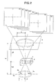
- [FIG. 2] FIG. 2 is an explanatory diagram showing an X-ray tomograph of the stereoradioscopic image constructing equipment according to the embodiment of the invention.
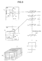
- [FIG. 3] FIG. 3 is an explanatory diagram showing accumulation of transmission images by the X-ray tomograph of the invention.
- [FIG. 4] FIG. 4 is an explanatory diagram showing accumulation of other transmission images by the X-ray tomograph of the invention.
- [FIG. 5] FIG. 5 is a perspective view showing an example of a subject to be examined by the X-ray tomograph of the invention.
- [FIG. 6] FIG. 6 is a plan view showing a transmission image to be processes by the X-ray tomograph of the invention.
- [FIG. 7] FIG. 7 is an explanatory view showing the X-ray tomograph of the invention and a transmission image of a subject by the X-ray tomograph.
- [FIG. 8A] FIG. 8A is a plan view showing a transmission image of a subject when a focal point is at a start position.
- [FIG. 8B] FIG. 8B is a plan view showing a transmission image of the subject when the focal point is rotated 45 degrees with respect to the start position.
- [FIG. 8C] FIG. 8C is a plan view showing a transmission image of the subject when the focal point is rotated 90 degrees with respect to the start position.
- [FIG. 8D] FIG. 8D is a plan view showing a transmission image of the subject when the focal point is rotated 225 degrees with respect to the start position.
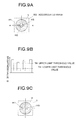
- [FIG. 9A] FIG. 9A is a plan view showing an accumulated image obtained by processing by the X-ray tomograph of the invention.
- [FIG. 9B] FIG. 9B is a view showing a luminance profile taken along line a-a of the accumulated image shown in Fig. 9A processed by the X-ray tomograph of the invention.
- [FIG. 9C] FIG. 9C is a plan view showing a tomographic image processed by the X-ray tomograph of the invention.
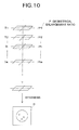
- [FIG. 10] FIG. 10 is an explanatory view showing synthesis of tomographic images by the stereoradioscopic image constructing equipment of the invention.
- Preferred embodiments of the invention will be described with reference to the drawings. It is to be understood that the present invention is not limited to the following embodiments.
- Fig. 1 shows the stereoradioscopic image constructing equipment of one embodiment of the invention. This stereoradioscopic image constructing equipment is provided with an X-ray CT (computed tomography)
apparatus 1 as an X-ray tomograph and animage processing device 2. The stereoradioscopic image constructing equipment is used for nondestructive inspection or the like of asubject 3. - The
X-ray CT apparatus 1 is provided with anX-ray tube 4 as an X-ray generator and an X-rayimage receiving element 5. TheX-raytube 4 and the X-rayimage receiving element 5 are disposed to face each other, and the X-rayimage receiving element 5 is connected to theimage processing device 2. Thesubject 3 is disposed between theX-ray tube 4 and the X-rayimage receiving element 5 and fixed on a fixing stand such as an X-Y-Z table (not shown). - The
X-ray tube 4 is formed to have a substantially cylindrical shape and disposed such that a central axis O agrees substantially with the center of the X-rayimage receiving element 5. TheX-ray tube 4 has aradiation plane 4a which is parallel to the X-rayimage receiving element 5. Theradiation plane 4a has an X-ray generatingsource 4b as a focal point for generation of X-rays toward thesubject 3. TheX-ray generating source 4b is disposed to be rotatable on a circumference having a prescribed radius r with the central axis O of theX-ray tube 4 as the center on theradiation plane 4a. In other words, theX-ray tube 4 has a function to move the positions of theX-ray generating source 4b, and theX-ray generating source 4b is configured to be rotatable , for example, one degree at a time with respect to the central axis O along the entire circumference, namely 360 degrees. - The X-ray
image receiving element 5 is, for example, a square planar image intensifier or a planar X-ray detector, and receives an X-ray image, which has passed through thesubject 3 after radiation from theX-ray generating source 4b of theX-ray tube 4, upon converting into a transmission image G which is an image signal. And, the transmission image G is sent to theimage processing device 2. - The
image processing device 2 has acomputer 6 as a processing arithmetic logic unit and amonitor 7 as an image display part connected to thecomputer 6. Thecomputer 6 processes the transmission image G transmitted from the X-rayimage receiving element 5 and has an image processing section and a stereoradioscopic image constructing section. - The image processing section of the
computer 6 cuts out square images from individual transmission images G0, G1, ..., Gi, ..., Gn corresponding to individual positions A0, A1, ..., Ai, ..., An of theX-ray generating source 4b of theX-ray tube 4 as shown in Fig. 2 through Fig. 4 and accumulates the cut-out images CG to create an accumulated image SG. The images are cut out into a square shape with a virtual center 0B, which is positioned on a circumference having a radius R from a center 0G of the transmission image, determined as the center. The cutout images CG correspond to arbitrary tomographic planes S which intersect in the axial direction of theX-ray tube 4 and are different from one another. - Laminographs, namely tomographic images T, of the subject 3 corresponding to the individual tomographic planes S are created by calculating a brightness value B of each pixel of the obtained accumulated image SG and extracting pixels having the brightness value B which is between a prescribed upper limit threshold value TH and a prescribed lower limit threshold value TL smaller than the upper limit threshold value TH.
- Here, a ratio between the radius r and the radius R is indicated as a ratio between a distance fod and a distance Δf as shown in Fig. 2. Specifically, it is expressed as R=r × Δf/fod, where the distance fod indicates a distance from the
radiation plane 4a of theX-ray tube 4 to the tomographic plane S of the subject 3, and the distance Δf indicates a difference between the distance fod and a distance fid from theradiation plane 4a of theX-ray tube 4 to the X-rayimage receiving element 5. The upper limit threshold value TH and the lower limit threshold value TL are previously determined according to the brightness value B of the pixels of the accumulated image SG. - The stereoradioscopic image constructing section of the
computer 6 creates a three-dimensional image, namely a stereoradioscopic image D, by composing upon correcting a geometrical enlargement ratio P of the tomographic images T created by the image processing section for each of the plural tomographic planes S which intersect in the axial direction of theX-ray tube 4 and are different from one another. Here, the geometrical enlargement ratio P is indicated as a ratio between the distance fid (a distance from theradiation plane 4a of theX-ray tube 4 to the X-ray image receiving element 5) and the distance fod (a distance from theradiation plane 4a of theX-ray tube 4 to the tomographic plane S of the subj ect 3) shown in Fig. 2. Specifically, it is expressed as P=fid/fod. - The
monitor 7 displays the tomographic images T of thesubj ect 3 and the stereoradioscopic image D created by thecomputer 6. - An X-ray tomographic process and a stereoradioscopic image constructing process according to an embodiment of the invention will be described with reference to Fig. 2 through Fig. 4.
- First, the
subject 3 is fixed to the fixing stand, and the rotating radius r of theX-ray generating source 4b of theX-ray tube 4 is determined such that an X-ray is radiated to a prescribed tomographic plane S1 of thesubject 3. - Then, an X-ray is radiated from the
X-ray generating source 4b located at A0 to the subject 3 as shown in Fig. 2. And, theX-ray generating source 4b is moved, for example, one degree at a time with respect to the central axis O along the circumference with the radius r on theradiation plane 4a, to convert the X-ray image of the subject 3 corresponding to a position Ai into a transmission image Gi. - At this time, the X-ray
image receiving element 5 has the center 0B of the X-ray image of the subject 3 positioned on a virtual circumference C1 with a radius R1 corresponding to the position of the tomographic plane S1 with a center 0G of the transmission images G as the center, and the X-ray image of the subject 3 rotates along the circumference about the center 0G of the transmission image G with the movement of theX-ray generating source 4b of theX-ray tube 4. - Then, the
computer 6 of theimage processing device 2 having received the transmission images G0, G1, ..., Gi, ..., Gn cuts out square images with the center 0B, which is positioned on the virtual circle C1 of the radius R1 from the center of the transmission images G0, G1, ..., Gi, ..., Gn as a center, and accumulates cutout images CG10, CG11, ..., CGli, ..., CG1n to create an accumulated image SG1. - Creation of the accumulated image will be described more specifically assuming that the
subject 3 has a shape as shown in, for example, Fig. 5 or a shape that a spherical substance has three holes H1, H2, H3 therein. - As shown in Fig. 6, the whole of the X-ray image of the subject 3 is moved such that its center is positioned on a circumference C with a radius R having the center 0G of the transmission images G as the center. At the same time, the hole H2 positioned outside of the tomographic plane S1 which passes through the center of the subject 3 as shown in Fig. 7 and Fig. 8A through Fig. 8D changes its positions within a circle with the center of the cutout images CGof the transmission images G0, G1, ..., Gi, ..., Gn determined as the center. As a result, the accumulated image SG has a small brightness value B of pixels at the position corresponding to the hole H2 because the brightness value B of the pixels at the position corresponding to the hole H2 cancel each other in the individual transmission images G0, G1, ..., Gi, ... , Gn as shown in Fig. 9A through Fig. 9C.
- The
computer 6 extracts pixels having the brightness value B between the upper limit threshold value TH and the lower limit threshold value TL from the individual pixels of the accumulated image SG1 to create the tomographic image T1 shown in Fig. 3. And, the tomographic image T1 is sent to and shown on themonitor 7. - Similarly, the
computer 6 of theimage processing device 2 creates square cutout images CGm0, CGm1, ..., CGmi, ..., CGmn with a center 0B, which is positioned on a virtual circle Cm having a radius Rm with respect to the transmission images G0, G1, ..., Gi, ... , Gn determined as the center, and accumulates the cutout images CGm0, CGm1, ... , CGmi, ..., CGmn to create the accumulated image SGm. And, pixels with the brightness value B between the upper limit threshold value TH and the lower limit threshold value TL are extracted from the pixels of the individual accumulated images SGm to create a tomographic image Tm corresponding to individual tomographic plane Sm. - Then, the
computer 6 corrects geometrical enlargement ratios P1, P2, ..., Pi, ..., Pm of individual tomographic images T1, T2, ..., Ti, ..., Tm corresponding to individual tomographic planes S1, S2, ..., Si, ... , Sm as shown in Fig. 10. Specifically, the individual tomographic images T1, T2, ..., Ti, ..., Tm are divided by the geometrical enlargement ratios P1, P2, ..., Pi, ... , Pm, and the individual tomographic images T1, T2, ..., Ti, ..., Tm having corrected the geometrical enlargement ratios P1, P2, ... , Pi, ..., Pm are synthesized by thecomputer 6 to create a stereoradioscopic image D. - Thus, according to the above embodiment, an X-ray is radiated to the subject 3 while moving the position of the
X-ray generating source 4b of theX-ray tube 4, and the transmission images G0, G1, ..., Gi, ..., Gn of the subject 3 by the X-rays with the different focal positions are received by the X-rayimage receiving element 5. And, the received transmission images G0, G1, ..., Gi, ..., Gn are processed by the image processing section of thecomputer 6 to obtain the tomographic image T. - Specifically, it is configured that the
X-ray generating source 4b of theX-ray tube 4 is moved along the circumference, the transmission images G0, G1, ..., Gi, ..., Gn of the subject 3 corresponding to the individual positions of theX-raygenerating source 4b are accumulated to create the accumulated image SG, and the pixels with the brightness value B of the accumulated image SG between the prescribed upper limit threshold value TH and the prescribed lower limit threshold value TL are extracted to create the tomographic images T. - Therefore, the
X-ray CT apparatus 1 which is a conventional X-ray transmission inspection apparatus is provided with a function to rotate the positions of theX-ray generating source 4b of theX-ray tube 4 along the circumference, so that the tomographic image T of the subject 3 can be obtained easily without disposing a movable mechanism for moving theX-ray tube 4 or the like. For example, a tomographic image of asoft subject 3 can also be obtained surely. - And, the stereoradioscopic image D can be obtained easily by synthesizing upon correcting the geometrical enlargement ratio P of the tomographic image T, so that the stereoradioscopic image constructing equipment can be made compact and inexpensive.
- Besides, the tomographic images T corresponding to the individual tomographic planes S can be obtained by one rotation of the
X-ray generating source 4b along the circumference, so that a photographing speed of the tomographic image T can be enhanced, anda time required to obtain the tomographic image T can be decreased regardless of the size of the subject 3 in comparison with the method to rotate and translate the X-ray tube or the subject. Therefore, if the subject 3 is a human, a burden on the subject can be reduced when photographing. - In the above-described embodiment, if the tomographic image T of the subject 3 can be obtained without fail, the
X-ray generating source 4b can be moved along a variety of orbits other than the circumference, such as a figure of 8 in a planar view. - According to the present invention, an tomographic image of a subject can be obtained easily without provision of a movable mechanism for moving, for example, an X-ray generator, an X-ray image receiving element or a subject, and an tomographic image of a soft subject or the like can also be obtained securely.
Claims (5)
- An X-ray tomograph, comprising:an X-ray generator having a function of moving a focal position and radiating X-rays toward a subject;an X-ray image receiving element for receiving a plurality of transmission images of the subj ect formed by the X-rays radiated from the X-ray generator while the focal position is moved; andan image processing section for creating a tomographic image by processing the plurality of transmission images of the subject received by the X-ray image receiving element.
- The X-ray tomograph according to claim 1,
wherein the X-ray generator is configured to make the focal position movable on a circumference; and
wherein the image processing section accumulates the transmission images of the subject corresponding to individual focal positions of the X-ray generator to create an accumulated image and extracts pixels having a brightness value of the accumulated image between a prescribed upper limit threshold value and a lower limit threshold value to create a tomographic image. - The X-ray tomograph according to claim 1 or 2,
wherein it is configured to create the tomographic image of the subject for each of a plurality of tomographic planes which intersect in prescribed directions and are different from one another. - A stereoradioscopic image constructing equipment, comprising:the X-ray tomograph according to any one of claims 1 to 3 ; anda stereoradioscopic image constructing section for creating a stereoradioscopic image by processing the plurality of tomographic images obtained by the X-ray tomograph.
- The stereoradioscopic image constructing equipment according to claim 4,
wherein the stereoradioscopic image constructing section corrects geometrical enlargement ratios of the plurality of tomographic images obtained by the X-ray tomograph and combines the corrected tomographic images to create a stereoradioscopic image.
Applications Claiming Priority (2)
| Application Number | Priority Date | Filing Date | Title |
|---|---|---|---|
| JP2004054625A JP2005241575A (en) | 2004-02-27 | 2004-02-27 | X-ray tomography apparatus and stereoscopic image forming apparatus |
| PCT/JP2005/003199 WO2005083403A1 (en) | 2004-02-27 | 2005-02-25 | X-ray tomograph and stereoradioscopic image constructing device |
Publications (1)
| Publication Number | Publication Date |
|---|---|
| EP1720004A1 true EP1720004A1 (en) | 2006-11-08 |
Family
ID=34908799
Family Applications (1)
| Application Number | Title | Priority Date | Filing Date |
|---|---|---|---|
| EP05710749A Withdrawn EP1720004A1 (en) | 2004-02-27 | 2005-02-25 | X-ray tomograph and stereoradioscopic image constructing device |
Country Status (6)
| Country | Link |
|---|---|
| US (1) | US7729468B2 (en) |
| EP (1) | EP1720004A1 (en) |
| JP (1) | JP2005241575A (en) |
| KR (1) | KR20060114720A (en) |
| CN (1) | CN1922475A (en) |
| WO (1) | WO2005083403A1 (en) |
Cited By (1)
| Publication number | Priority date | Publication date | Assignee | Title |
|---|---|---|---|---|
| CN109923403A (en) * | 2016-11-01 | 2019-06-21 | 株式会社岛津制作所 | Method for correcting imaging magnification of radiation tomography apparatus |
Families Citing this family (11)
| Publication number | Priority date | Publication date | Assignee | Title |
|---|---|---|---|---|
| US8125220B2 (en) * | 2005-12-22 | 2012-02-28 | Koninklijke Philips Electronics N.V. | Magnetic induction tomography system and method |
| EP2239560B1 (en) * | 2007-12-27 | 2020-04-22 | Omron Corporation | X-ray examining apparatus and x-ray examining method |
| TWI394490B (en) * | 2008-09-10 | 2013-04-21 | Omron Tateisi Electronics Co | X-ray inspecting device and method for inspecting x ray |
| JP2012024519A (en) * | 2010-07-28 | 2012-02-09 | Fujifilm Corp | Radiological image radiographing and displaying method and apparatus |
| JP5275377B2 (en) * | 2011-01-19 | 2013-08-28 | ヤマハ発動機株式会社 | X-ray inspection equipment |
| CN102253061B (en) * | 2011-04-19 | 2013-07-10 | 东南大学 | Vertical cone beam CT (Computed Tomography) imaging calibration system and method applying same |
| KR101823743B1 (en) * | 2014-01-23 | 2018-01-31 | 가부시키가이샤 죠부 | X-ray inspection apparatus and x-ray inspection method |
| CN104374786B (en) * | 2014-11-27 | 2017-01-11 | 中国科学院上海应用物理研究所 | Synchrotron-radiation X-ray CT (computed tomography) axis correcting system and method |
| CN104483334B (en) * | 2014-12-22 | 2017-11-10 | 中国矿业大学 | A kind of method of visual representation cement-based material moisture spatial distribution and content |
| US10697904B2 (en) * | 2016-03-31 | 2020-06-30 | Job Corporation | X-ray detection system, X-ray device, and device and method for processing X-ray detection data |
| JP6843683B2 (en) * | 2017-04-11 | 2021-03-17 | 東芝Itコントロールシステム株式会社 | X-ray inspection equipment |
Family Cites Families (22)
| Publication number | Priority date | Publication date | Assignee | Title |
|---|---|---|---|---|
| JP4054402B2 (en) * | 1997-04-25 | 2008-02-27 | 株式会社東芝 | X-ray tomography equipment |
| US3973127A (en) * | 1974-10-09 | 1976-08-03 | Tokyo Shibaura Electric Co., Ltd. | X-ray tomography apparatus |
| US4105922A (en) | 1977-04-11 | 1978-08-08 | General Electric Company | CT number identifier in a computed tomography system |
| CA1182997A (en) | 1980-12-08 | 1985-02-26 | Gunter J. Lissy | Powder spray booth |
| JPS58218948A (en) * | 1982-06-16 | 1983-12-20 | 横河電機株式会社 | Data converting apparatus |
| JPS62227320A (en) * | 1986-03-28 | 1987-10-06 | 株式会社東芝 | Stereoscopic image display device |
| US5081656A (en) * | 1987-10-30 | 1992-01-14 | Four Pi Systems Corporation | Automated laminography system for inspection of electronics |
| US5621811A (en) * | 1987-10-30 | 1997-04-15 | Hewlett-Packard Co. | Learning method and apparatus for detecting and controlling solder defects |
| US5097492A (en) * | 1987-10-30 | 1992-03-17 | Four Pi Systems Corporation | Automated laminography system for inspection of electronics |
| US5561696A (en) * | 1987-10-30 | 1996-10-01 | Hewlett-Packard Company | Method and apparatus for inspecting electrical connections |
| US4926452A (en) | 1987-10-30 | 1990-05-15 | Four Pi Systems Corporation | Automated laminography system for inspection of electronics |
| US5259012A (en) * | 1990-08-30 | 1993-11-02 | Four Pi Systems Corporation | Laminography system and method with electromagnetically directed multipath radiation source |
| US5278884A (en) * | 1992-12-18 | 1994-01-11 | General Electric Company | Complete 3D CT data acquisition using practical scanning paths on the surface of a sphere |
| JPH075125A (en) * | 1993-06-17 | 1995-01-10 | Fujitsu Ltd | Method and apparatus for X-ray tomography |
| JP2501411B2 (en) | 1993-08-12 | 1996-05-29 | 株式会社東芝 | Active matrix display device |
| EP0683389A1 (en) * | 1994-05-12 | 1995-11-22 | Kabushiki Kaisha Toshiba | Laminograph and inspection and repair device using the same |
| JP3614214B2 (en) * | 1995-08-29 | 2005-01-26 | 東芝Itコントロールシステム株式会社 | Tomography equipment |
| JPH10227749A (en) * | 1997-02-14 | 1998-08-25 | Matsushita Electric Ind Co Ltd | X-ray inspection apparatus and X-ray inspection method |
| US6002739A (en) * | 1998-04-28 | 1999-12-14 | Hewlett Packard Company | Computed tomography with iterative reconstruction of thin cross-sectional planes |
| US6483890B1 (en) * | 2000-12-01 | 2002-11-19 | Koninklijke Philips Electronics, N.V. | Digital x-ray imaging apparatus with a multiple position irradiation source and improved spatial resolution |
| JP4778163B2 (en) * | 2001-07-13 | 2011-09-21 | 株式会社吉田製作所 | Linear motion X-ray tomography system |
| US20080247505A1 (en) * | 2007-04-07 | 2008-10-09 | Rohit Patnaik | Xray device for planar tomosynthesis |
-
2004
- 2004-02-27 JP JP2004054625A patent/JP2005241575A/en active Pending
-
2005
- 2005-02-25 WO PCT/JP2005/003199 patent/WO2005083403A1/en not_active Ceased
- 2005-02-25 CN CNA2005800059502A patent/CN1922475A/en active Pending
- 2005-02-25 EP EP05710749A patent/EP1720004A1/en not_active Withdrawn
- 2005-02-25 KR KR1020067019576A patent/KR20060114720A/en not_active Ceased
- 2005-02-25 US US10/590,517 patent/US7729468B2/en not_active Expired - Lifetime
Non-Patent Citations (1)
| Title |
|---|
| See references of WO2005083403A1 * |
Cited By (2)
| Publication number | Priority date | Publication date | Assignee | Title |
|---|---|---|---|---|
| CN109923403A (en) * | 2016-11-01 | 2019-06-21 | 株式会社岛津制作所 | Method for correcting imaging magnification of radiation tomography apparatus |
| CN109923403B (en) * | 2016-11-01 | 2022-01-04 | 株式会社岛津制作所 | Imaging magnification correction method for radiation tomography apparatus |
Also Published As
| Publication number | Publication date |
|---|---|
| JP2005241575A (en) | 2005-09-08 |
| US7729468B2 (en) | 2010-06-01 |
| KR20060114720A (en) | 2006-11-07 |
| CN1922475A (en) | 2007-02-28 |
| US20080267347A1 (en) | 2008-10-30 |
| WO2005083403A1 (en) | 2005-09-09 |
Similar Documents
| Publication | Publication Date | Title |
|---|---|---|
| US7436927B2 (en) | Imaging apparatus and method for the operation thereof | |
| US7729468B2 (en) | X-ray tomograph and stereoradioscopic image construction equipment | |
| EP2262428B1 (en) | Fast tomosynthesis scanner apparatus and ct-based method based on rotational step-and-shoot image acquisition without focal spot motion during continuous tube movement for use in cone-beam volume ct mammography imaging | |
| EP0117524B1 (en) | Method of obtaining x-ray ct image and apparatus for utilizing the same method | |
| US6574296B2 (en) | Computer tomography unit and method for operating same | |
| US8693618B2 (en) | Scanner device and method for computed tomography imaging | |
| US20040252811A1 (en) | Radiographic apparatus | |
| JPH0242347A (en) | Dynamic tomograph system computerized | |
| US8634515B2 (en) | Method and apparatus for obtaining panoramic image | |
| JP2010500146A (en) | Image acquisition for image stitching with rotation of radiation detector | |
| KR101425530B1 (en) | Apparatus for Correction of Object Classification Algorism Using X-ray Computed Tomography | |
| JP5060862B2 (en) | Tomography equipment | |
| JP6430239B2 (en) | Medical diagnostic imaging equipment | |
| US6728331B1 (en) | Method and system for trauma application of CT imaging | |
| JP4640589B2 (en) | X-ray equipment | |
| US6798860B1 (en) | Methods and apparatus for deconvolving imaging data | |
| JP4561990B2 (en) | X-ray equipment | |
| JP5251264B2 (en) | X-ray CT system | |
| CN110731790B (en) | Image forming apparatus and image forming method | |
| JP4479503B2 (en) | Tomography equipment | |
| JP4600661B2 (en) | X-ray CT system | |
| JP4505256B2 (en) | Computed tomography equipment | |
| JPH04307035A (en) | Radiographic apparatus | |
| US6510194B1 (en) | Method and apparatus for acquiring transmitted-radiation image data | |
| JP4609643B2 (en) | X-ray CT system |
Legal Events
| Date | Code | Title | Description |
|---|---|---|---|
| PUAI | Public reference made under article 153(3) epc to a published international application that has entered the european phase |
Free format text: ORIGINAL CODE: 0009012 |
|
| 17P | Request for examination filed |
Effective date: 20060825 |
|
| AK | Designated contracting states |
Kind code of ref document: A1 Designated state(s): DE FR GB |
|
| DAX | Request for extension of the european patent (deleted) | ||
| RBV | Designated contracting states (corrected) |
Designated state(s): DE FR GB |
|
| STAA | Information on the status of an ep patent application or granted ep patent |
Free format text: STATUS: THE APPLICATION IS DEEMED TO BE WITHDRAWN |
|
| 18D | Application deemed to be withdrawn |
Effective date: 20090901 |