EP1719926A1 - Skew contact double ball bearing and pre-load adding method therefor - Google Patents
Skew contact double ball bearing and pre-load adding method therefor Download PDFInfo
- Publication number
- EP1719926A1 EP1719926A1 EP05719326A EP05719326A EP1719926A1 EP 1719926 A1 EP1719926 A1 EP 1719926A1 EP 05719326 A EP05719326 A EP 05719326A EP 05719326 A EP05719326 A EP 05719326A EP 1719926 A1 EP1719926 A1 EP 1719926A1
- Authority
- EP
- European Patent Office
- Prior art keywords
- balls
- ball bearing
- diameter
- double row
- preload
- Prior art date
- Legal status (The legal status is an assumption and is not a legal conclusion. Google has not performed a legal analysis and makes no representation as to the accuracy of the status listed.)
- Withdrawn
Links
Images



Classifications
-
- F—MECHANICAL ENGINEERING; LIGHTING; HEATING; WEAPONS; BLASTING
- F16—ENGINEERING ELEMENTS AND UNITS; GENERAL MEASURES FOR PRODUCING AND MAINTAINING EFFECTIVE FUNCTIONING OF MACHINES OR INSTALLATIONS; THERMAL INSULATION IN GENERAL
- F16C—SHAFTS; FLEXIBLE SHAFTS; ELEMENTS OR CRANKSHAFT MECHANISMS; ROTARY BODIES OTHER THAN GEARING ELEMENTS; BEARINGS
- F16C19/00—Bearings with rolling contact, for exclusively rotary movement
- F16C19/54—Systems consisting of a plurality of bearings with rolling friction
- F16C19/546—Systems with spaced apart rolling bearings including at least one angular contact bearing
- F16C19/547—Systems with spaced apart rolling bearings including at least one angular contact bearing with two angular contact rolling bearings
- F16C19/548—Systems with spaced apart rolling bearings including at least one angular contact bearing with two angular contact rolling bearings in O-arrangement
-
- F—MECHANICAL ENGINEERING; LIGHTING; HEATING; WEAPONS; BLASTING
- F16—ENGINEERING ELEMENTS AND UNITS; GENERAL MEASURES FOR PRODUCING AND MAINTAINING EFFECTIVE FUNCTIONING OF MACHINES OR INSTALLATIONS; THERMAL INSULATION IN GENERAL
- F16C—SHAFTS; FLEXIBLE SHAFTS; ELEMENTS OR CRANKSHAFT MECHANISMS; ROTARY BODIES OTHER THAN GEARING ELEMENTS; BEARINGS
- F16C19/00—Bearings with rolling contact, for exclusively rotary movement
- F16C19/02—Bearings with rolling contact, for exclusively rotary movement with bearing balls essentially of the same size in one or more circular rows
- F16C19/14—Bearings with rolling contact, for exclusively rotary movement with bearing balls essentially of the same size in one or more circular rows for both radial and axial load
- F16C19/18—Bearings with rolling contact, for exclusively rotary movement with bearing balls essentially of the same size in one or more circular rows for both radial and axial load with two or more rows of balls
- F16C19/181—Bearings with rolling contact, for exclusively rotary movement with bearing balls essentially of the same size in one or more circular rows for both radial and axial load with two or more rows of balls with angular contact
- F16C19/182—Bearings with rolling contact, for exclusively rotary movement with bearing balls essentially of the same size in one or more circular rows for both radial and axial load with two or more rows of balls with angular contact in tandem arrangement
-
- F—MECHANICAL ENGINEERING; LIGHTING; HEATING; WEAPONS; BLASTING
- F16—ENGINEERING ELEMENTS AND UNITS; GENERAL MEASURES FOR PRODUCING AND MAINTAINING EFFECTIVE FUNCTIONING OF MACHINES OR INSTALLATIONS; THERMAL INSULATION IN GENERAL
- F16C—SHAFTS; FLEXIBLE SHAFTS; ELEMENTS OR CRANKSHAFT MECHANISMS; ROTARY BODIES OTHER THAN GEARING ELEMENTS; BEARINGS
- F16C25/00—Bearings for exclusively rotary movement adjustable for wear or play
- F16C25/06—Ball or roller bearings
-
- F—MECHANICAL ENGINEERING; LIGHTING; HEATING; WEAPONS; BLASTING
- F16—ENGINEERING ELEMENTS AND UNITS; GENERAL MEASURES FOR PRODUCING AND MAINTAINING EFFECTIVE FUNCTIONING OF MACHINES OR INSTALLATIONS; THERMAL INSULATION IN GENERAL
- F16H—GEARING
- F16H57/00—General details of gearing
- F16H57/02—Gearboxes; Mounting gearing therein
- F16H57/037—Gearboxes for accommodating differential gearings
-
- F—MECHANICAL ENGINEERING; LIGHTING; HEATING; WEAPONS; BLASTING
- F16—ENGINEERING ELEMENTS AND UNITS; GENERAL MEASURES FOR PRODUCING AND MAINTAINING EFFECTIVE FUNCTIONING OF MACHINES OR INSTALLATIONS; THERMAL INSULATION IN GENERAL
- F16C—SHAFTS; FLEXIBLE SHAFTS; ELEMENTS OR CRANKSHAFT MECHANISMS; ROTARY BODIES OTHER THAN GEARING ELEMENTS; BEARINGS
- F16C2229/00—Setting preload
-
- F—MECHANICAL ENGINEERING; LIGHTING; HEATING; WEAPONS; BLASTING
- F16—ENGINEERING ELEMENTS AND UNITS; GENERAL MEASURES FOR PRODUCING AND MAINTAINING EFFECTIVE FUNCTIONING OF MACHINES OR INSTALLATIONS; THERMAL INSULATION IN GENERAL
- F16C—SHAFTS; FLEXIBLE SHAFTS; ELEMENTS OR CRANKSHAFT MECHANISMS; ROTARY BODIES OTHER THAN GEARING ELEMENTS; BEARINGS
- F16C2240/00—Specified values or numerical ranges of parameters; Relations between them
- F16C2240/40—Linear dimensions, e.g. length, radius, thickness, gap
- F16C2240/46—Gap sizes or clearances
-
- F—MECHANICAL ENGINEERING; LIGHTING; HEATING; WEAPONS; BLASTING
- F16—ENGINEERING ELEMENTS AND UNITS; GENERAL MEASURES FOR PRODUCING AND MAINTAINING EFFECTIVE FUNCTIONING OF MACHINES OR INSTALLATIONS; THERMAL INSULATION IN GENERAL
- F16C—SHAFTS; FLEXIBLE SHAFTS; ELEMENTS OR CRANKSHAFT MECHANISMS; ROTARY BODIES OTHER THAN GEARING ELEMENTS; BEARINGS
- F16C2240/00—Specified values or numerical ranges of parameters; Relations between them
- F16C2240/40—Linear dimensions, e.g. length, radius, thickness, gap
- F16C2240/70—Diameters; Radii
- F16C2240/80—Pitch circle diameters [PCD]
-
- F—MECHANICAL ENGINEERING; LIGHTING; HEATING; WEAPONS; BLASTING
- F16—ENGINEERING ELEMENTS AND UNITS; GENERAL MEASURES FOR PRODUCING AND MAINTAINING EFFECTIVE FUNCTIONING OF MACHINES OR INSTALLATIONS; THERMAL INSULATION IN GENERAL
- F16C—SHAFTS; FLEXIBLE SHAFTS; ELEMENTS OR CRANKSHAFT MECHANISMS; ROTARY BODIES OTHER THAN GEARING ELEMENTS; BEARINGS
- F16C2361/00—Apparatus or articles in engineering in general
- F16C2361/61—Toothed gear systems, e.g. support of pinion shafts
-
- F—MECHANICAL ENGINEERING; LIGHTING; HEATING; WEAPONS; BLASTING
- F16—ENGINEERING ELEMENTS AND UNITS; GENERAL MEASURES FOR PRODUCING AND MAINTAINING EFFECTIVE FUNCTIONING OF MACHINES OR INSTALLATIONS; THERMAL INSULATION IN GENERAL
- F16H—GEARING
- F16H48/00—Differential gearings
- F16H48/38—Constructional details
- F16H48/42—Constructional details characterised by features of the input shafts, e.g. mounting of drive gears thereon
- F16H2048/423—Constructional details characterised by features of the input shafts, e.g. mounting of drive gears thereon characterised by bearing arrangement
-
- F—MECHANICAL ENGINEERING; LIGHTING; HEATING; WEAPONS; BLASTING
- F16—ENGINEERING ELEMENTS AND UNITS; GENERAL MEASURES FOR PRODUCING AND MAINTAINING EFFECTIVE FUNCTIONING OF MACHINES OR INSTALLATIONS; THERMAL INSULATION IN GENERAL
- F16H—GEARING
- F16H57/00—General details of gearing
- F16H57/02—Gearboxes; Mounting gearing therein
- F16H57/021—Shaft support structures, e.g. partition walls, bearing eyes, casing walls or covers with bearings
Definitions
- the present invention relates to an oblique contact double row ball bearing for supporting a pinion shaft of a differential device additionally provided in a vehicle or the like under a free rotation, more specifically to an oblique contact double row ball bearing in which pitch circle diameters of double rows are different to each other, in other words, raceway diameters of the double rows are different to each other, and a method of imparting a preload to the ball bearing.
- a tapered roller bearing is used as a roller bearing for supporting a pinion shaft of a differential device additionally provided in a vehicle, or the like under a free rotation.
- the tapered roller bearing has a large load capacity, however, its rotation torque is large. Therefore, an oblique contact ball bearing (angular contact ball bearing) may be incorporated into the differential device or the like in place of the tapered roller bearing (for example, see the Patent Document 1), or an oblique contact double row ball bearing called a tandem double row ball bearing in which pitch circle diameters of double rows are different to each other, in other words, raceway diameters of the double rows are different to each other, may occasionally be incorporated into the differential device or the like.
- the oblique contact double row ball bearing having the pitch circle diameters different to each other is effectively used particularly for the opinion shaft of the differential device or the like because the rotation torque thereof is smaller than that of the tapered roller bearing and the load capacity is sufficiently large.
- Patent Document 1 No. 2003-156128 of the Japanese Patent Application Laid-Open
- the preload is controlled (adjusted) in the bearing through the measurement of the rotation torque of the bearing. Therefore, a range where the preload is set is increased as the rotation torque is larger, which facilitates the adjustment.
- the tapered roller bearing is advantageous in its large load capacity and at the same time the rotation torque thereof is large. As a result, the adjustment range of the preload to be set with respect to the bearing is large, which makes it easy to control the preload.
- the rotation torque is small and the adjustment range of the preload to be set with respect to the bearing is thereby reduced. As a result, it is difficult for the preload to be set with a high accuracy.
- a main object of the present invention is to facilitate the control of the preload in the oblique contact ball bearing.
- an oblique contact double row ball bearing according to the present invention comprises double rows of balls axially interposed in raceways of inner and outer rings, wherein an inner clearance between the balls in one of the rows and the raceway in which the balls are rolled, and an inner clearance between the balls in the other row and the raceway in which the balls are rolled are different to each other.
- the inner clearance between the balls in one of the rows and the raceway of the inner and outer rings corresponding to the one of the rows in which the balls are rolled, and the inner clearance between the balls in the other row and the raceway of the inner and outer rings corresponding to the other row in which the balls are rolled, are set to be different to each other, and then a load is given to the inner and outer rings so that the inner clearances are sequentially reduced in order to provide the preload to the inner and outer rings.
- any one of the clearances may be reduced earlier than the other.
- the preload to be imparted to the bearing is generally obtained through measurement of a rotation torque.
- the case of imparting the preload to the oblique contact double row ball bearing is considered here.
- a thrust load S to be imparted to the inner and outer rings is hypothetically a "S2" value
- comparison of an adjustment range "T1" of a rotation torque T in a conventional oblique contact double row ball bearing to an adjustment range "T2" of the rotation torque T in the oblique contact double row ball bearing according to the present invention which correspond to the "S2" value, it becomes T2 > T1.
- the preload can be adjusted in the range wider in the oblique contact ball bearing according to the present invention than that of the conventional oblique contact ball bearing, which consequently makes it easy to impart the preload with a high accuracy.
- the preload may be set while the thrust load "S2" is being adjusted in the range of [S1] - [S3] in view of its tolerance in setting the preload.
- T4 > T3 is obtained.
- the preload can be adjusted in the adjustment range wider than that of the conventional oblique contact bearing by making the rotation torque large, and the preload can be thereby accurately and easily imparted.
- Fig. 1 is a sectional view illustrating a schematic constitution of a differential device.
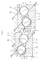
- Fig. 2 is a sectional view in which double row ball bearings are enlarged.
- a differential device 1 comprises a differential case 2.
- the differential case 2 comprises a front case 3 and a rear case 4. These cases 3 and 4 are coupled to each other by a bolt / nut 2a so as to thereby be integrated.
- Annular walls 27A and 27B in which ball bearings are applied are formed in the front case 3.
- the differential case 2 comprises internally a differential speed-change mechanism 5 for differentially gearing right and left wheels, and a pinion shaft (drive pinion) 7 having a pinion gear 6 on one side thereof.
- the pinion gear 6 is meshed with a ring gear 8 of the differential speed-change mechanism 5.
- a shaft part 9 of the pinion shaft 7 is formed in a stepwise shape so that a diameter thereof is gradually reduced on the other side than one side thereof.
- the one side of the shaft part 9 of the pinion shaft 7 is supported by the annular wall 27A of the front case 3 so as to freely rotate around an axial center via a first double row ball bearing 10.
- the other side of the shaft part 9 of the pinion shaft 7 is supported by the annular wall 27B of the front case 3 so as to freely rotate around the axial center via a second double row ball bearing 25.
- the first double row ball bearing 10 is an oblique contact double row ball bearing, and comprises a single first outer ring 11 fitted to an inner peripheral surface of the annular wall 27A and a first assembly component 21.
- the first assembly component 21 is assembled into the first outer ring 11 from the pinion-gear side toward the opposite side of the pinion gear 6 (hereinafter, referred to as counter-pinion-gear side) along an axial direction so as to thereby constitute the first double row ball bearing 10.
- the first outer ring 11 has a structure of a counterbored outer ring. More specifically, the first outer ring 11 comprises a large diameter outer ring raceway 11a on the pinion-gear side and a small diameter outer ring raceway 11b on the counter-pinion-gear side. A planar part 11c is formed between the large diameter outer ring raceway 11a and the small diameter outer ring raceway 11b. The planar part 11c has a diameter larger than that of the small diameter outer ring raceway 11b and continuous to the large diameter outer ring raceway 11a. An inner peripheral surface of the first outer ring 11 is thus formed in the stepwise shape.
- the first assembly component 21 comprises a single first inner ring 13, a large-diameter-side row of balls 15, a small-diameter-side row of balls 16, and retainers 19 and 20.
- the first inner ring 13 has a structure of a counterbored inner ring. More specifically, the first inner ring 13 comprises a large diameter inner ring raceway 13a and a small diameter inner ring raceway 13b.
- the large diameter inner ring raceway 13a faces the large diameter outer ring raceway 11a in a radial direction.
- the small diameter inner ring raceway 13b faces the small diameter outer ring raceway 11b in a radial direction.
- a planar part 13c is formed between the large diameter inner ring raceway 13a and the small diameter inner ring raceway 13b.
- the planar part 13c has a diameter larger than that of the small diameter inner ring raceway 13b and continuous to the large diameter inner ring raceway 13a.
- An outer peripheral surface of the first inner ring 13 is thus formed in the stepwise shape.
- the large-diameter-side row of balls 15 are fitted to place on the pinion-gear side, in other words, between the large diameter outer ring raceway 11a and the large diameter inner ring raceway 13a.
- the small-diameter-side row of balls 16 are fitted to place on the counter-pinion-gear side, in other words, between the small diameter outer ring raceway 11b and the small diameter inner ring raceway 13b.
- a contact angle of the row of balls 15 and a contact angle of the row of balls 16 have a same direction.
- a line of action ⁇ 1 in accordance with the contact angle of the row of balls 15 and a line of action ⁇ 2 in accordance with the contact angle of the row of balls 16 face each other in a such a direction that an angle ⁇ 1 (not shown) made by the lines of action ⁇ 1 and ⁇ 2 is 0° or an acute angle (0° ⁇ ⁇ 1 ⁇ 90°).
- Such a constitution is adopted so that a preload is imparted to the both rows of balls 15 and 16 in a same direction (in the present case, direction from the pinion-gear side toward the counter-pinion-gear side).
- the lines of action ⁇ 1 and ⁇ 2 are tilted in such a direction that outer-diameter sides thereof are on the counter-pinion-gear side and inner-diameter sides thereof are on the pinion-gear side with respect to a thrust surface.
- the lines of action ⁇ 1 and ⁇ 2 are tilted in the upper-right direction in Fig. 2 and FIG. 3.
- the retainers 19 and 20 retain balls 17 and 18 respectively constituting the rows of balls 15 and 16 at a position with circumferentially equal interval.
- the pinion shaft 17 is inserted through the first inner ring 13, and an end surface of the first inner ring 13 abuts an end surface of the pinion gear 6 from the axial-center direction.
- the first inner ring 13 is sandwiched from the axial-center direction between the end surface of the pinion gear 6 and a plastic spacer 23 externally mounted on the shaft part 9 of the pinion shaft 7 at an intermediate position thereof for setting the preload.
- a diameter of the ball 17 in the large-diameter-side row of balls 15 and a diameter of the ball 18 in the small-diameter-side row of balls 16 are equal to each other, while pitch circle diameters D1 and D2 of the respective rows of balls 15 and 16 are different to each other. More specifically, the pitch circle diameter D1 of the large-diameter-side row of balls 15 is set to a value larger than that of the pitch circle diameter D2 of the small-diameter-side row of balls 16.
- the first double row ball bearing 10 has a double row structure (rows of balls 15 and 16) in which the two rows of balls have the different pitch circle diameters D1 and D2 each other.
- the balls 17 of the large-diameter-side row of balls 15 are placed so as to space at a predetermined radial clearance ⁇ 1 between the large diameter outer ring raceway 11a and the large diameter inner ring raceway 13a in an initial state before assembling into the differential device.
- the balls 18 of the small-diameter-side row of balls 16 are placed so as to space at a predetermined radial clearance ⁇ 1 smaller than the radial clearance ⁇ 1 ( ⁇ 1 > ⁇ 1) between the small diameter outer ring raceway 11b and the small diameter inner ring raceway 13b in the initial state before assembling into the differential device.
- the second double row ball bearing 25 is an oblique contact double row ball bearing, and comprises a single second outer ring 12 fitted to an inner peripheral surface of the annular wall 27B and a second assembly component 22.
- the second assembly component 22 is assembled into the second outer ring 12 from the counter-pinion-gear side toward the pinion-gear side along the axial-center direction.
- the second outer ring 12 has a structure of a counterbored outer ring. More specifically, the second outer ring 12 comprises a small diameter outer ring raceway 12a on the pinion-gear side and a large diameter outer ring raceway 12b on the counter-pinion-gear side. A planar part 12c is formed between the small diameter outer ring raceway 12a and the large diameter outer ring raceway 12b. The planar part 12c has a diameter larger than that of the small diameter outer ring raceway 12b and continuous to the large diameter outer ring raceway 12a. Accordingly, an inner peripheral surface of the second outer ring 12 is thus formed in the stepwise shape.
- the second assembly component 22 comprises a single second inner ring 14, a small-diameter-side row of balls 28, a large-diameter-side row of balls 29, and retainers 32 and 33.
- the second inner ring 14 has a structure of a counterbored inner ring. More specifically, the second inner ring 14 comprises a small diameter inner ring raceway 14a and a large diameter inner ring raceway 14b.
- the small diameter inner ring raceway 14a faces the small diameter outer ring raceway 12a in a radial direction.
- the large diameter inner ring raceway 14b faces the large diameter outer ring raceway 12b in a radial direction.
- Aplanarpart 14c is formedbetween the small diameter inner ring raceway 14a and the large diameter inner ring raceway 14b.
- the planar part 14c has a diameter smaller than that of the large diameter inner ring raceway 14b and continuous to the small diameter inner ring raceway 14a.
- An outer peripheral surface of the first inner ring 14 is thus formed in the stepwise shape.
- the pinion shaft 7 is inserted through the second inner ring 14.
- the second inner ring 14 is sandwiched from the axial-center direction between the plastic spacer 23 for setting the preload and a shield 37.
- the small-diameter-side row of balls 28 are placed to fit on the pinion-gear side, that is, between the small diameter outer ring raceway 12a and the small diameter inner ring raceway 14a.
- the large-diameter-side row of balls 29 are placed to fit on the counter-pinion-gear side, that is, between the large diameter outer ring raceway 12b and the large diameter inner ring raceway 14b.
- a contact angle of the row of balls 28 and a contact angle of the row of balls 29 have a same direction.
- a line of action ⁇ 3 in accordance with the contact angle of the row of balls 28 and a line of action ⁇ 4 in accordance with the contact angle of the row of balls 29 face each other in a such a direction that an angle ⁇ 2 (not shown) made by the lines of action ⁇ 3 and ⁇ 4 is 0° or an acute angle (0° ⁇ ⁇ 2 ⁇ 90°).
- Such a constitution is adopted so that the preload is imparted to the both rows of balls 28 and 29 in a same direction (in the present case, direction from the counter-pinion-gear side toward the pinion-gear side).
- the lines of action ⁇ 3 and ⁇ 4 are tilted in such a direction that outer-diameter sides thereof are on the pinion-gear side and inner-diameter sides thereof are on the counter-pinion-gear side with respect to the thrust surface.
- the lines of action are tilted on the downside in Figs. 2 and 3.
- the retainers 32 and 33 retain balls 30 and 31 respectively constituting the rows of balls 28 and 29 at a position with circumferentially equal intervals.
- the inner-diameter sides of the lines of action ⁇ 1 and ⁇ 2 of the first double row ball bearing 10 are on the pinion-gear side with respect to the thrust surface
- the outer-diameter sides of the lines of action ⁇ 3 and ⁇ 4 of the second double row ball bearing 25 are on the pinion-gear side with respect to the thrust surface, so that the gradients of the lines of action in accordance with the contact angles of the bearings 10 and 25 are thereby reverse to each other.
- Such a constitution is adopted in order to reverse the directions where the preload is imparted in the bearings 10 and 25.
- a diameter of the ball 30 in the small-diameter-side row of balls 28 and a diameter of the ball 31 in the large-diameter-side row of balls 29 are equal to each other, while pitch circle diameters D3 and D4 of the respective rows of balls 28 and 29 are different to each other. More specifically, the pitch circle diameter D3 of the large-diameter-side row of balls 28 is set to a value smaller than that of the pitch circle diameter D4 of the small-diameter-side row of balls 29.
- the second double row ball bearing 25 has a double row structure (rows of balls 28 and 29) in which the two rows of balls have the different pitch circle diameters D3 and D4 to each other.
- the balls 30 of the small-diameter-side row of balls 28 are placed to space at a predetermined radial clearance ⁇ 2 between the small diameter outer ring raceway 12a and the small diameter inner ring raceway 14a in the initial state before assembling into the differential device.
- the balls 31 of the large-diameter-side row of balls 29 are placed to space at a predetermined radial clearance ⁇ 2 smaller than the radial clearance ⁇ 2 ( ⁇ 2 > ⁇ 2) between the large diameter outer ring raceway 12b and the large diameter inner ring raceway 14b in the initial state before assembling into the differential device.
- An oil-circulating path 40 is formed between an outer wall of the front case 3 and one side of the annular wall 27A.
- An oil inlet 41 of the oil circulating path 40 is opened toward a ring-gear-8 side of the oil circulating path 40, while an oil outlet 42 of the oil circulating path 40 is opened toward between the annular walls 27A and 27B.
- the differential device 1 comprises a companion flange 43.
- the companion flange 43 comprises a barrel part 44 and a flange part 45 formed as united with the barrel part 44.
- the barrel part 44 is externally mounted on the shaft part 9 of the pinion shaft 7 on the other side thereof, namely, on a drive-shaft side (not shown) thereof.
- the shield 37 is interposed between an end surface of the barrel part 44 and an end surface of the second inner ring 14 of the second double row ball bearing 25.
- An oil seal 46 is arranged between an outer peripheral surface of the barrel part 44 and an inner peripheral surface of an opening of the front case 3 on the other side thereof.
- a seal protective cap 47 is attached to the other-side opening of the front case 3.
- the oil seal 46 is covered with the seal protective cap 47.
- a screw part 48 is formed at an end part of the shaft part 9 on the other side thereof.
- the screw part 48 is protruded into a central recess part 43a of the flange part 45.
- a nut 49 is screwed into the screw part 48 so that the first inner ring 13 of the first double row ball bearing 10 and the second inner ring 14 of the second double row ball bearing 25 are sandwiched between the end surface of the pinion gear 6 and an end surface of the companion flange 43 in the axial-center direction.
- a predetermined preload is imparted to the first double row ball bearing 10 and the second double row ball bearing 25 via the shield 37 and the plastic spacer 23.
- a lubricating oil 50 is reserved in the differential case 2 at a predetermined level L in a state where the operation is halted.
- the lubricating oil 50 is raised upward by the rotation of the ring gear 8 when the operation starts, travels through the oil circulating path 40 in the front case 3, and is introduced and supplied to upper parts of the first double row ball bearing 10 and the second double row ball bearing 25.
- the lubricating oil 50 circulates in the differential case 2 so as to lubricate the first double row ball bearing 10 and the second double row ball bearing 25.
- the first double row ball bearing 10 and the second double row ball bearing 25 are assembled in advance.
- the radial clearance ⁇ 1 is adjusted to be smaller than the radial clearance ⁇ 1 as described earlier. More specifically, the respective parts of the first double row ball bearing 10 are formed so as to obtain the foregoing relationship between the clearances, and further, shapes of the respective parts are adjusted so that the clearances in the predetermined state can be obtained in the assembly.
- an clearance between the small-diameter-side row of balls 28, and the small diameter outer ring raceway 12a and the small diameter inner ring raceway 14a is adjusted so that the radial clearance ⁇ 2 is smaller than the radial clearance ⁇ 2 as described earlier.
- the respective parts of the second double row ball bearing 25 are formed so as to obtain the foregoing relationship between the clearances, and further, shapes of the respective parts are adjusted so that the clearance in the predetermined state can be obtained in the assembly.
- the first double row ball bearing 10 is disassembled into the first outer ring 11 and the first assembly component 21, and the second double row ball bearing 25 is disassembled into the second outer ring 12 and the second assembly component 22. Then, the first double row ball bearing 10 and the second double row ball bearing 25 are incorporated into the differential device 1. More specifically, the first outer ring 11 and the second outer ring 12 are respectively pressed into the annular walls 27A and 27B.
- the first outer ring 11 is incorporated into the front case 3 and further pressed in the axial-center direction from the one-side opening of the front case 3 until it abuts a step part formed on the annular wall 27A.
- the second outer ring 12 is pressed in the axial-center direction from the other-side opening of the front case 3 until it abuts a step part formed on the annular wall 28B.
- the first assembly component 21 (specifically, first inner ring 13) is inserted through the pinion shaft 7. Then, the first assembly component 21 is incorporated into the pinion shaft 7 so as to locate on the pinion-gear-6 side of the shaft part 9 of the pinion shaft 7.
- the pinion shaft 7 into which the first assembly component 21 is incorporated is inserted through the one-side opening of the front case 3 from the small-diameter side thereof. At the time, the pinion shaft 7 is inserted so that the balls 18 of the small-diameter-side row of balls 16 of the first assembly component 21 are fitted into the small-diameter outer ring raceway 11b of the first outer ring 11. Further, the pinion shaft 7 is inserted so that the balls 17 of the large-diameter-side row of balls 15 are fitted into the large-diameter outer ring raceway 11a of the first outer ring 11.
- the small-diameter-side row of balls 18 is arranged to be closer to a rear side in the direction where the pinion shaft 7 is inserted (the counter-pinion-gear side) than the large-diameter-side row of balls 16.
- the plastic spacer 23 is inserted by externally fitting to the shaft part 9 of the pinion shaft 7 from the other-side opening of the front case 3.
- the second assembly component 22 (specifically, second inner ring 14) is inserted by externally fitting to the shaft part 9 of the pinion shaft 7 from the other-side opening of the front case 3.
- the small-diameter-side row of balls 28 is arranged to be closer to a rear side in the direction where the pinion shaft 7 is inserted (pinion-gear side) than the large-diameter-side row of balls 29.
- the shield 37 is inserted through the shaft part 9 of the pinion shaft 7 from the other-side opening of the front case 3.
- the oil seal 46 is fixed on the shaft part 9 of the pinion shaft 7 from the other-side opening of the front case 3.
- the seal protective cap 47 is mounted on the other-side opening of the front case 3.
- the barrel part 44 of the companion flange 43 is inserted through the seal protective cap 47 so that the end surface of the barrel part 44 abuts the shield 37.
- the nut 49 is screwed into the screw part 48.
- a thrust load is imparted to the first double row ball bearing 10 and the second double row ball bearing 25, and a predetermined preload is imparted thereto.
- the direction to impart the preload id done as below.
- the preload is imparted to the first double row ball bearing 10 along the direction from the pinion-gear side toward the counter-pinion-gear side, while the preload is imparted to the second double row ball bearing 25 along the direction from the counter-pinion-gear side toward the pinion-gear side.
- the preload is imparted to the first and second double row ball bearings 10 and 25 in the reverse directions.
- the radial clearance ⁇ 1 is set to a value smaller than that of the radial clearance ⁇ 1. Therefore, when the thrust load for imparting the preload is applied to the first double row ball bearing 10, the balls 18 of the small-diameter-side row of balls 16 are fitted into the raceways 11b and 13b at the predetermined contact angle before the balls 17 of the large-diameter-side row of balls 15 are fitted into the raceways 11b and 13b, and thereby the rotation torque is generated.
- the radial clearance ⁇ 2 is set to a value smaller than that of the radial clearance ⁇ 2 in a similar manner. Therefore, when the thrust load for imparting the preload is applied to the second double row ball bearing 25, the balls 31 of the large-diameter-side row of balls 29 are fitted into the raceways 12b and 14b at the predetermined contact angle before the balls 30 of the small-diameter-side row of balls 28 are fitted into the raceways 12a and 14a, and thereby the rotation torque is generated.
- the radial clearance ⁇ 1 that is on the side of the smaller clearance
- the balls 18 of the small-diameter-side row of balls 16 the small diameter outer ring raceway 11b and the small diameter inner ring raceway 13b are thereby already fitted with respect to one another at the predetermined contact angle in the first double row ball bearing 10
- the radial clearance ⁇ 2 that is on the side of the smaller clearance, is reduced so that the balls 31 of the large-diameter-side row of balls 29 and the raceways 12b and 14b are fitted with respect to one another at the predetermined contact angle in the second double row ball bearing 25.
- the radial clearance ⁇ 1 that is on the side of the larger clearance
- the radial clearance ⁇ 2 that is on the side of the larger clearance
- the radial clearance ⁇ 2 is reduced so that the balls 30 of the small-diameter-side row of balls 28 and the raceways 12a and 14a are fitted with respect to one another at the predetermined contact angle in the second double row ball bearing 25, and thereby the rotation torque is generated.
- the rotation torque is selectively obtained in the row of balls 16 alone in the first double row ball bearing 10, and thereafter the rotation torque resulting from the synthesized rotation torques of the rows of balls 15 and 16 is obtained with a time lag.
- the rotation torque is selectively obtained in the row of balls 29 alone, and thereafter the rotation torque resulting from the synthesized rotation torques of the rows of balls 28 and 29 is obtained with a time lag. Accordingly, a maximum rotation torque thereby obtained is increased, which expands the range of the adjustable torque.
- the adjustment range of the preload to be set is thereby increased, and the preload control is consequently facilitated.
- a graph of Fig. 4 shows a relationship between the thrust load S (preload) imparted to the oblique contact double row ball bearing and the rotation torque T corresponding to the thrust load S.
- the thrust load applied to the oblique contact double row ball bearing can be known through the measurement of the rotation torque T.
- a broken line 60 shows a result of the conventional oblique contact double row ball bearing (double row ball bearing in which the pitch circle diameters of the respective rows are different to each other), while a solid line 61 shows a result of the first and second oblique contact double row ball bearings 10 and 25 according to the present invention (oblique contact double row ball bearings in which the pitch circle diameters of the respective rows are different to each other). Comparing a tilt of the broken line 60 to that of the solid line 61 to each other, the tilt of the solid line 61 is larger than that of the broken line 60. A reason is described below.
- the balls 18 of the small-diameter-side row of balls 16 and the raceways 11b and 13b are first fitted with respect to one another so that the initial rotation torque is generated, and thereafter, the balls 17 of the large-diameter-side row of balls 15 and the raceways 11a and 13a are fitted with respect to one another so that the rotation torque is further generated.
- the balls 31 of the large-diameter-side row of balls 29 and the raceways 12b and 14b are first fitted with respect to one another so that the initial rotation torque is generated, and thereafter, the balls 30 of the small-diameter-side row of balls 28 and the raceways 12a and 14a are fitted with respect to one another so that the rotation torque is further generated.
- the rotation torque can be largely set and the range of the torque to be set can be increased in comparison to the conventional oblique contact double row ball bearing in which the balls of the both rows are simultaneously fitted into the raceways, and the gradient of the full line 61 is larger than that of the broken line 60.
- the thrust load "S2" to be imparted is in the range from “S1" through “S3” in terms of its tolerance.
- the adjustment range of the rotation torque T in the conventional oblique contact double row ball bearing is T3
- the adjustment range of the rotation torque T is T4 in the first and second double row ball bearings 10 and 25 according to the present invention, that is, it is T4 > T3 as shown in Fig. 5.
- the first and second double row ball bearings 10 and 25 according to the present invention can achieve the adjustment range wider than that of the conventional double rowball bearing when it is tried to obtain the same preload.
- the thrust load S preload
Landscapes
- Engineering & Computer Science (AREA)
- General Engineering & Computer Science (AREA)
- Mechanical Engineering (AREA)
- Rolling Contact Bearings (AREA)
- Support Of The Bearing (AREA)
- Mounting Of Bearings Or Others (AREA)
Abstract
Description
- The present invention relates to an oblique contact double row ball bearing for supporting a pinion shaft of a differential device additionally provided in a vehicle or the like under a free rotation, more specifically to an oblique contact double row ball bearing in which pitch circle diameters of double rows are different to each other, in other words, raceway diameters of the double rows are different to each other, and a method of imparting a preload to the ball bearing.
- A tapered roller bearing is used as a roller bearing for supporting a pinion shaft of a differential device additionally provided in a vehicle, or the like under a free rotation. The tapered roller bearing has a large load capacity, however, its rotation torque is large. Therefore, an oblique contact ball bearing (angular contact ball bearing) may be incorporated into the differential device or the like in place of the tapered roller bearing (for example, see the Patent Document 1), or an oblique contact double row ball bearing called a tandem double row ball bearing in which pitch circle diameters of double rows are different to each other, in other words, raceway diameters of the double rows are different to each other, may occasionally be incorporated into the differential device or the like.
- The oblique contact double row ball bearing having the pitch circle diameters different to each other is effectively used particularly for the opinion shaft of the differential device or the like because the rotation torque thereof is smaller than that of the tapered roller bearing and the load capacity is sufficiently large.
- In the case of incorporating these bearings into the differential device, the bearings are managed and stored in a state where a preload as prescribed is applied thereto.
Patent Document 1: No.2003-156128 of the Japanese Patent Application Laid-Open - The preload is controlled (adjusted) in the bearing through the measurement of the rotation torque of the bearing. Therefore, a range where the preload is set is increased as the rotation torque is larger, which facilitates the adjustment. As described earlier, the tapered roller bearing is advantageous in its large load capacity and at the same time the rotation torque thereof is large. As a result, the adjustment range of the preload to be set with respect to the bearing is large, which makes it easy to control the preload. However, in the oblique contact ball bearing, which has the structure of the ball bearing, the rotation torque is small and the adjustment range of the preload to be set with respect to the bearing is thereby reduced. As a result, it is difficult for the preload to be set with a high accuracy.
- A main object of the present invention is to facilitate the control of the preload in the oblique contact ball bearing.
- In order to achieve the foregoing object, an oblique contact double row ball bearing according to the present invention comprises double rows of balls axially interposed in raceways of inner and outer rings, wherein an inner clearance between the balls in one of the rows and the raceway in which the balls are rolled, and an inner clearance between the balls in the other row and the raceway in which the balls are rolled are different to each other.
- In a method of imparting a preload to the oblique contact double row ball bearing according to the present invention, the inner clearance between the balls in one of the rows and the raceway of the inner and outer rings corresponding to the one of the rows in which the balls are rolled, and the inner clearance between the balls in the other row and the raceway of the inner and outer rings corresponding to the other row in which the balls are rolled, are set to be different to each other, and then a load is given to the inner and outer rings so that the inner clearances are sequentially reduced in order to provide the preload to the inner and outer rings.
- In the oblique contact double row ball bearing according to the present invention, any one of the clearances may be reduced earlier than the other.
- The preload to be imparted to the bearing is generally obtained through measurement of a rotation torque. The case of imparting the preload to the oblique contact double row ball bearing is considered here. In this case, when a thrust load S to be imparted to the inner and outer rings is hypothetically a "S2" value, comparison of an adjustment range "T1" of a rotation torque T in a conventional oblique contact double row ball bearing to an adjustment range "T2" of the rotation torque T in the oblique contact double row ball bearing according to the present invention, which correspond to the "S2" value, it becomes T2 > T1. Therefore, when it is tried to obtain the same preload, the preload can be adjusted in the range wider in the oblique contact ball bearing according to the present invention than that of the conventional oblique contact ball bearing, which consequently makes it easy to impart the preload with a high accuracy.
- In addition, the preload may be set while the thrust load "S2" is being adjusted in the range of [S1] - [S3] in view of its tolerance in setting the preload. Such a case is considered. Comparing an adjustment range [T3] of the rotation torque T in the conventional bearing to an adjustment range [T4] of the rotation torque T in the bearing according to the present invention, T4 > T3 is obtained. When it is tried to obtain the same preload, the adjustment range of the rotation torque T (in other words, adjustment range of the preload) is increased in the bearing according to the present invention in comparison to that of the conventional bearing. As a result, the preload can be easily and accurately imparted.
- According to the present invention, the preload can be adjusted in the adjustment range wider than that of the conventional oblique contact bearing by making the rotation torque large, and the preload can be thereby accurately and easily imparted.
-
- Fig. 1 is a sectional view illustrating a schematic constitution of a differential device according to a preferred embodiment of the present invention.
- Fig. 2 is a sectional view in which double row ball bearings in the differential device are enlarged.
- Fig. 3 is a sectional view in which the double row ball bearings are further enlarged.
- Fig. 4 is a sectional view illustrating a state where the double row ball bearings are being assembled.
- Fig. 5 is a graph showing a relationship between a thrust load and a rotation torque.
-
- 1
- differential device
- 2
- differential case
- 6
- pinion gear
- 7
- pinion shaft
- 10
- first double row ball bearing
- 25
- second double row ball bearing
- 11
- first outer ring
- 21
- first assembly component
- 13
- first inner ring
- 12
- second outer ring
- 22
- second assembly component
- 14
- second inner ring
- 28,29
- row of balls
- 30,31
- balls
- A preferred embodiment of the present invention is described referring to the drawings. Fig. 1 is a sectional view illustrating a schematic constitution of a differential device. Fig. 2 is a sectional view in which double row ball bearings are enlarged.
- As shown in Fig. 1, a
differential device 1 comprises adifferential case 2. Thedifferential case 2 comprises afront case 3 and arear case 4. Thesecases nut 2a so as to thereby be integrated.Annular walls front case 3. - The
differential case 2 comprises internally a differential speed-change mechanism 5 for differentially gearing right and left wheels, and a pinion shaft (drive pinion) 7 having apinion gear 6 on one side thereof. Thepinion gear 6 is meshed with aring gear 8 of the differential speed-change mechanism 5. Ashaft part 9 of thepinion shaft 7 is formed in a stepwise shape so that a diameter thereof is gradually reduced on the other side than one side thereof. - The one side of the
shaft part 9 of thepinion shaft 7 is supported by theannular wall 27A of thefront case 3 so as to freely rotate around an axial center via a first doublerow ball bearing 10. The other side of theshaft part 9 of thepinion shaft 7 is supported by theannular wall 27B of thefront case 3 so as to freely rotate around the axial center via a second doublerow ball bearing 25. - As shown in Fig. 2, the first double
row ball bearing 10 is an oblique contact double row ball bearing, and comprises a single firstouter ring 11 fitted to an inner peripheral surface of theannular wall 27A and afirst assembly component 21. Thefirst assembly component 21 is assembled into the firstouter ring 11 from the pinion-gear side toward the opposite side of the pinion gear 6 (hereinafter, referred to as counter-pinion-gear side) along an axial direction so as to thereby constitute the first doublerow ball bearing 10. - The first
outer ring 11 has a structure of a counterbored outer ring. More specifically, the firstouter ring 11 comprises a large diameterouter ring raceway 11a on the pinion-gear side and a small diameterouter ring raceway 11b on the counter-pinion-gear side. Aplanar part 11c is formed between the large diameterouter ring raceway 11a and the small diameterouter ring raceway 11b. Theplanar part 11c has a diameter larger than that of the small diameterouter ring raceway 11b and continuous to the large diameterouter ring raceway 11a. An inner peripheral surface of the firstouter ring 11 is thus formed in the stepwise shape. - The
first assembly component 21 comprises a single firstinner ring 13, a large-diameter-side row ofballs 15, a small-diameter-side row ofballs 16, andretainers inner ring 13 has a structure of a counterbored inner ring. More specifically, the firstinner ring 13 comprises a large diameterinner ring raceway 13a and a small diameterinner ring raceway 13b. The large diameterinner ring raceway 13a faces the large diameterouter ring raceway 11a in a radial direction. The small diameterinner ring raceway 13b faces the small diameterouter ring raceway 11b in a radial direction. Aplanar part 13c is formed between the large diameterinner ring raceway 13a and the small diameterinner ring raceway 13b. Theplanar part 13c has a diameter larger than that of the small diameterinner ring raceway 13b and continuous to the large diameterinner ring raceway 13a. An outer peripheral surface of the firstinner ring 13 is thus formed in the stepwise shape. - The large-diameter-side row of
balls 15 are fitted to place on the pinion-gear side, in other words, between the large diameterouter ring raceway 11a and the large diameterinner ring raceway 13a. The small-diameter-side row ofballs 16 are fitted to place on the counter-pinion-gear side, in other words, between the small diameterouter ring raceway 11b and the small diameterinner ring raceway 13b. - In the first double
row ball bearing 10, a contact angle of the row ofballs 15 and a contact angle of the row ofballs 16 have a same direction. In other words, a line of action γ1 in accordance with the contact angle of the row ofballs 15 and a line of action γ2 in accordance with the contact angle of the row ofballs 16 face each other in a such a direction that an angle θ1 (not shown) made by the lines ofaction γ 1 and γ2 is 0° or an acute angle (0° ≦ θ1 < 90°). Such a constitution is adopted so that a preload is imparted to the both rows ofballs action γ 1 and γ2 are tilted in such a direction that outer-diameter sides thereof are on the counter-pinion-gear side and inner-diameter sides thereof are on the pinion-gear side with respect to a thrust surface. To be brief, the lines of action γ1 and γ2 are tilted in the upper-right direction in Fig. 2 and FIG. 3. Theretainers balls balls - The
pinion shaft 17 is inserted through the firstinner ring 13, and an end surface of the firstinner ring 13 abuts an end surface of thepinion gear 6 from the axial-center direction. The firstinner ring 13 is sandwiched from the axial-center direction between the end surface of thepinion gear 6 and aplastic spacer 23 externally mounted on theshaft part 9 of thepinion shaft 7 at an intermediate position thereof for setting the preload. - In the first double
row ball bearing 10, a diameter of theball 17 in the large-diameter-side row ofballs 15 and a diameter of theball 18 in the small-diameter-side row ofballs 16 are equal to each other, while pitch circle diameters D1 and D2 of the respective rows ofballs balls 15 is set to a value larger than that of the pitch circle diameter D2 of the small-diameter-side row ofballs 16. As described, the first doublerow ball bearing 10 has a double row structure (rows ofballs 15 and 16) in which the two rows of balls have the different pitch circle diameters D1 and D2 each other. - As shown in an enlarged view of Fig. 3, the
balls 17 of the large-diameter-side row ofballs 15 are placed so as to space at a predetermined radial clearance α1 between the large diameterouter ring raceway 11a and the large diameterinner ring raceway 13a in an initial state before assembling into the differential device. Theballs 18 of the small-diameter-side row ofballs 16 are placed so as to space at a predetermined radial clearance β1 smaller than the radial clearance α1 (α1 > β1) between the small diameterouter ring raceway 11b and the small diameterinner ring raceway 13b in the initial state before assembling into the differential device. - The second double
row ball bearing 25 is an oblique contact double row ball bearing, and comprises a single secondouter ring 12 fitted to an inner peripheral surface of theannular wall 27B and asecond assembly component 22. Thesecond assembly component 22 is assembled into the secondouter ring 12 from the counter-pinion-gear side toward the pinion-gear side along the axial-center direction. - The second
outer ring 12 has a structure of a counterbored outer ring. More specifically, the secondouter ring 12 comprises a small diameterouter ring raceway 12a on the pinion-gear side and a large diameterouter ring raceway 12b on the counter-pinion-gear side. Aplanar part 12c is formed between the small diameterouter ring raceway 12a and the large diameterouter ring raceway 12b. Theplanar part 12c has a diameter larger than that of the small diameterouter ring raceway 12b and continuous to the large diameterouter ring raceway 12a. Accordingly, an inner peripheral surface of the secondouter ring 12 is thus formed in the stepwise shape. - The
second assembly component 22 comprises a single secondinner ring 14, a small-diameter-side row ofballs 28, a large-diameter-side row ofballs 29, andretainers 32 and 33. The secondinner ring 14 has a structure of a counterbored inner ring. More specifically, the secondinner ring 14 comprises a small diameterinner ring raceway 14a and a large diameterinner ring raceway 14b. The small diameterinner ring raceway 14a faces the small diameterouter ring raceway 12a in a radial direction. The large diameterinner ring raceway 14b faces the large diameterouter ring raceway 12b in a radial direction.Aplanarpart 14c is formedbetween the small diameterinner ring raceway 14a and the large diameterinner ring raceway 14b. Theplanar part 14c has a diameter smaller than that of the large diameterinner ring raceway 14b and continuous to the small diameterinner ring raceway 14a. An outer peripheral surface of the firstinner ring 14 is thus formed in the stepwise shape. - The
pinion shaft 7 is inserted through the secondinner ring 14. The secondinner ring 14 is sandwiched from the axial-center direction between theplastic spacer 23 for setting the preload and ashield 37. - The small-diameter-side row of
balls 28 are placed to fit on the pinion-gear side, that is, between the small diameterouter ring raceway 12a and the small diameterinner ring raceway 14a. The large-diameter-side row ofballs 29 are placed to fit on the counter-pinion-gear side, that is, between the large diameterouter ring raceway 12b and the large diameterinner ring raceway 14b. - In the second double
row ball bearing 25, a contact angle of the row ofballs 28 and a contact angle of the row ofballs 29 have a same direction. In other words, a line of action γ3 in accordance with the contact angle of the row ofballs 28 and a line of action γ4 in accordance with the contact angle of the row ofballs 29 face each other in a such a direction that an angle θ2 (not shown) made by the lines ofaction γ 3 andγ 4 is 0° or an acute angle (0° ≦ θ2 < 90°). Such a constitution is adopted so that the preload is imparted to the both rows ofballs retainers 32 and 33 retainballs balls - Thus, the inner-diameter sides of the lines of action γ1 and γ2 of the first double
row ball bearing 10 are on the pinion-gear side with respect to the thrust surface, while the outer-diameter sides of the lines of action γ3 and γ4 of the second doublerow ball bearing 25 are on the pinion-gear side with respect to the thrust surface, so that the gradients of the lines of action in accordance with the contact angles of thebearings bearings - In the second double
row ball bearing 25, a diameter of theball 30 in the small-diameter-side row ofballs 28 and a diameter of theball 31 in the large-diameter-side row ofballs 29 are equal to each other, while pitch circle diameters D3 and D4 of the respective rows ofballs balls 28 is set to a value smaller than that of the pitch circle diameter D4 of the small-diameter-side row ofballs 29. As described, the second doublerow ball bearing 25 has a double row structure (rows ofballs 28 and 29) in which the two rows of balls have the different pitch circle diameters D3 and D4 to each other. - As shown in an enlarged view of Fig. 3, the
balls 30 of the small-diameter-side row ofballs 28 are placed to space at a predetermined radial clearance α2 between the small diameterouter ring raceway 12a and the small diameterinner ring raceway 14a in the initial state before assembling into the differential device. Theballs 31 of the large-diameter-side row ofballs 29 are placed to space at a predetermined radial clearance β2 smaller than the radial clearance α2 (α2 > β2) between the large diameterouter ring raceway 12b and the large diameterinner ring raceway 14b in the initial state before assembling into the differential device. - An oil-circulating
path 40 is formed between an outer wall of thefront case 3 and one side of theannular wall 27A. Anoil inlet 41 of theoil circulating path 40 is opened toward a ring-gear-8 side of theoil circulating path 40, while anoil outlet 42 of theoil circulating path 40 is opened toward between theannular walls - The
differential device 1 comprises acompanion flange 43. Thecompanion flange 43 comprises abarrel part 44 and aflange part 45 formed as united with thebarrel part 44. - The
barrel part 44 is externally mounted on theshaft part 9 of thepinion shaft 7 on the other side thereof, namely, on a drive-shaft side (not shown) thereof. Theshield 37 is interposed between an end surface of thebarrel part 44 and an end surface of the secondinner ring 14 of the second doublerow ball bearing 25. - An
oil seal 46 is arranged between an outer peripheral surface of thebarrel part 44 and an inner peripheral surface of an opening of thefront case 3 on the other side thereof. A sealprotective cap 47 is attached to the other-side opening of thefront case 3. Theoil seal 46 is covered with the sealprotective cap 47. Ascrew part 48 is formed at an end part of theshaft part 9 on the other side thereof. Thescrew part 48 is protruded into acentral recess part 43a of theflange part 45. Anut 49 is screwed into thescrew part 48 so that the firstinner ring 13 of the first doublerow ball bearing 10 and the secondinner ring 14 of the second doublerow ball bearing 25 are sandwiched between the end surface of thepinion gear 6 and an end surface of thecompanion flange 43 in the axial-center direction. A predetermined preload is imparted to the first doublerow ball bearing 10 and the second doublerow ball bearing 25 via theshield 37 and theplastic spacer 23. - In the
differential device 1 thus constituted, a lubricatingoil 50 is reserved in thedifferential case 2 at a predetermined level L in a state where the operation is halted. The lubricatingoil 50 is raised upward by the rotation of thering gear 8 when the operation starts, travels through theoil circulating path 40 in thefront case 3, and is introduced and supplied to upper parts of the first doublerow ball bearing 10 and the second doublerow ball bearing 25. Thereby, the lubricatingoil 50 circulates in thedifferential case 2 so as to lubricate the first doublerow ball bearing 10 and the second doublerow ball bearing 25. - Next, a method of assembling the
differential device 1 is described referring to a partial sectional view of Fig. 4. In order to assemble thedifferential device 1, the first doublerow ball bearing 10 and the second doublerow ball bearing 25 are assembled in advance. Before the first doublerow ball bearing 10 is assembled, the radial clearance β1 is adjusted to be smaller than the radial clearance α1 as described earlier. More specifically, the respective parts of the first doublerow ball bearing 10 are formed so as to obtain the foregoing relationship between the clearances, and further, shapes of the respective parts are adjusted so that the clearances in the predetermined state can be obtained in the assembly. - Before the seconddoublerowballbearing25 is assembled, an clearance between the small-diameter-side row of
balls 28, and the small diameterouter ring raceway 12a and the small diameterinner ring raceway 14a is adjusted so that the radial clearance β2 is smaller than the radial clearance α2 as described earlier. More specifically, the respective parts of the second doublerow ball bearing 25 are formed so as to obtain the foregoing relationship between the clearances, and further, shapes of the respective parts are adjusted so that the clearance in the predetermined state can be obtained in the assembly. - After the foregoing adjustments and preparations are made, the first double
row ball bearing 10 is disassembled into the firstouter ring 11 and thefirst assembly component 21, and the second doublerow ball bearing 25 is disassembled into the secondouter ring 12 and thesecond assembly component 22. Then, the first doublerow ball bearing 10 and the second doublerow ball bearing 25 are incorporated into thedifferential device 1. More specifically, the firstouter ring 11 and the secondouter ring 12 are respectively pressed into theannular walls front case 3 and therear case 4 are still separated, the firstouter ring 11 is incorporated into thefront case 3 and further pressed in the axial-center direction from the one-side opening of thefront case 3 until it abuts a step part formed on theannular wall 27A. Then, the secondouter ring 12 is pressed in the axial-center direction from the other-side opening of thefront case 3 until it abuts a step part formed on the annular wall 28B. - The first assembly component 21 (specifically, first inner ring 13) is inserted through the
pinion shaft 7. Then, thefirst assembly component 21 is incorporated into thepinion shaft 7 so as to locate on the pinion-gear-6 side of theshaft part 9 of thepinion shaft 7. - The
pinion shaft 7 into which thefirst assembly component 21 is incorporated is inserted through the one-side opening of thefront case 3 from the small-diameter side thereof. At the time, thepinion shaft 7 is inserted so that theballs 18 of the small-diameter-side row ofballs 16 of thefirst assembly component 21 are fitted into the small-diameterouter ring raceway 11b of the firstouter ring 11. Further, thepinion shaft 7 is inserted so that theballs 17 of the large-diameter-side row ofballs 15 are fitted into the large-diameterouter ring raceway 11a of the firstouter ring 11. In order to realize the assembly process described above, the small-diameter-side row ofballs 18 is arranged to be closer to a rear side in the direction where thepinion shaft 7 is inserted (the counter-pinion-gear side) than the large-diameter-side row ofballs 16. - Next, the
plastic spacer 23 is inserted by externally fitting to theshaft part 9 of thepinion shaft 7 from the other-side opening of thefront case 3. Subsequently, the second assembly component 22 (specifically, second inner ring 14) is inserted by externally fitting to theshaft part 9 of thepinion shaft 7 from the other-side opening of thefront case 3. In order to realize the foregoing insertion by externally fitting, the small-diameter-side row ofballs 28 is arranged to be closer to a rear side in the direction where thepinion shaft 7 is inserted (pinion-gear side) than the large-diameter-side row ofballs 29. - Thereafter, the
shield 37 is inserted through theshaft part 9 of thepinion shaft 7 from the other-side opening of thefront case 3. Further, theoil seal 46 is fixed on theshaft part 9 of thepinion shaft 7 from the other-side opening of thefront case 3. The sealprotective cap 47 is mounted on the other-side opening of thefront case 3. Thebarrel part 44 of thecompanion flange 43 is inserted through the sealprotective cap 47 so that the end surface of thebarrel part 44 abuts theshield 37. Then, thenut 49 is screwed into thescrew part 48. Thereby, a thrust load is imparted to the first doublerow ball bearing 10 and the second doublerow ball bearing 25, and a predetermined preload is imparted thereto. The direction to impart the preload id done as below. The preload is imparted to the first doublerow ball bearing 10 along the direction from the pinion-gear side toward the counter-pinion-gear side, while the preload is imparted to the second doublerow ball bearing 25 along the direction from the counter-pinion-gear side toward the pinion-gear side. Thus, the preload is imparted to the first and second doublerow ball bearings - In the
differential device 1, theradial clearance β 1 is set to a value smaller than that of the radial clearance α1. Therefore, when the thrust load for imparting the preload is applied to the first doublerow ball bearing 10, theballs 18 of the small-diameter-side row ofballs 16 are fitted into theraceways balls 17 of the large-diameter-side row ofballs 15 are fitted into theraceways - In the same way, in the
differential device 1, the radial clearance β2 is set to a value smaller than that of the radial clearance α2 in a similar manner. Therefore, when the thrust load for imparting the preload is applied to the second doublerow ball bearing 25, theballs 31 of the large-diameter-side row ofballs 29 are fitted into theraceways balls 30 of the small-diameter-side row ofballs 28 are fitted into theraceways - In the first double
row ball bearing 10 and the second doublerow ball bearing 25, the initial rotation torques are obtained as described, and the larger thrust load which is further applied so that the preload at a necessary level is applied. Explanation is given below. - In the state where the initial rotation torques are generated, as described, the radial clearance β1, that is on the side of the smaller clearance, is reduced, and the
balls 18 of the small-diameter-side row ofballs 16, the small diameterouter ring raceway 11b and the small diameterinner ring raceway 13b are thereby already fitted with respect to one another at the predetermined contact angle in the first doublerow ball bearing 10, while the radial clearance β2, that is on the side of the smaller clearance, is reduced so that theballs 31 of the large-diameter-side row ofballs 29 and theraceways row ball bearing 25. - When the thrust load is further imparted to the first double
row ball bearing 10 and the second doublerow ball bearing 25 in the described state, the radial clearance α1, that is on the side of the larger clearance, is reduced so that theballs 17 of the large-diameter-side row ofballs 15 and theraceways row ball bearing 10, and thereby the rotation torque is generated. In a similar manner, the radial clearance α2, that is on the side of the larger clearance, is reduced so that theballs 30 of the small-diameter-side row ofballs 28 and theraceways row ball bearing 25, and thereby the rotation torque is generated. - By slightly shifting the fitting timing in the respective rows of balls as described, the rotation torque is selectively obtained in the row of
balls 16 alone in the first doublerow ball bearing 10, and thereafter the rotation torque resulting from the synthesized rotation torques of the rows ofballs row ball bearing 25, the rotation torque is selectively obtained in the row ofballs 29 alone, and thereafter the rotation torque resulting from the synthesized rotation torques of the rows ofballs - A graph of Fig. 4 shows a relationship between the thrust load S (preload) imparted to the oblique contact double row ball bearing and the rotation torque T corresponding to the thrust load S. The thrust load applied to the oblique contact double row ball bearing can be known through the measurement of the rotation torque T.
- In the drawing, a
broken line 60 shows a result of the conventional oblique contact double row ball bearing (double row ball bearing in which the pitch circle diameters of the respective rows are different to each other), while asolid line 61 shows a result of the first and second oblique contact doublerow ball bearings broken line 60 to that of thesolid line 61 to each other, the tilt of thesolid line 61 is larger than that of thebroken line 60. A reason is described below. - As described, in the first double
row ball bearing 10, theballs 18 of the small-diameter-side row ofballs 16 and theraceways balls 17 of the large-diameter-side row ofballs 15 and theraceways - In a similar manner, in the second
double rowball bearing 25, theballs 31 of the large-diameter-side row ofballs 29 and theraceways balls 30 of the small-diameter-side row ofballs 28 and theraceways - As a result, the rotation torque can be largely set and the range of the torque to be set can be increased in comparison to the conventional oblique contact double row ball bearing in which the balls of the both rows are simultaneously fitted into the raceways, and the gradient of the
full line 61 is larger than that of thebroken line 60. - Description is given here, for example, to a case where it is tried to obtain the "S2" value as the thrust load S referring to a graph shown in Fig. 5. Because the tilt of the
solid line 61 is larger than that of thebroken line 60, the adjustment range of the rotation torque T corresponding to the "S2" value is T1 in the broken line 60 (conventional example), while the adjustment rage of the rotation torque T is T2 in the first and second doublerow ball bearings row ball bearings - Consideration is done about a case where the thrust load "S2" to be imparted is in the range from "S1" through "S3" in terms of its tolerance. In this case, the adjustment range of the rotation torque T in the conventional oblique contact double row ball bearing is T3, while the adjustment range of the rotation torque T is T4 in the first and second double
row ball bearings row ball bearings
Claims (8)
- An oblique contact double row ball bearing comprising double rows of balls axially interposed in between raceways of inner and outer rings, wherein
an inner clearance between the balls in one of the rows and the raceway in which the balls are rolled and an inner clearance between the balls in the other row and the raceway in which the balls are rolled, are different to each other. - The oblique contact double row ball bearing according to Claim 1, wherein the inner clearance is a radial clearance.
- The oblique contact double row ball bearing according to Claim 1, wherein pitch circle diameters of the both rows are different to each other.
- The oblique contact double row ball bearing according to Claim 1, wherein a contact angle of the ball in one of the rows and a contact angle of the ball in the other row have a same direction.
- A method of imparting a preload to an oblique contact double rowballbearing in which double rows of balls are arranged in between raceways of inner and outer rings with inner clearances, wherein
the inner clearance between the balls in one of the rows and the raceway of the inner and outer rings corresponding to the one of the rows in which the balls are rolled, and the inner clearance between the balls in the other row and the raceway of the inner and outer rings corresponding to the other row in which the balls are rolled are set to be different to each other, and then
a load is given to the inner and outer rings so that the inner clearances are sequentially reduced in order to impart the preload to the inner and outer rings. - The method of imparting the preload to the oblique contact double row ball bearing according to Claim 5, wherein
the inner clearance is a radial clearance, and
a thrust load is given to the inner and outer rings in order to impart the preload. - The method of imparting the preload to the oblique contact double row ball bearing according to Claim 5, wherein
pitch circle diameters of the double rows are different to each other. - The method of imparting the preload to the oblique contact double row ball bearing according to Claim 5, wherein
a contact angle of the ball in one of the rows and a contact angle of the ball in the other row have a same direction.
Applications Claiming Priority (2)
| Application Number | Priority Date | Filing Date | Title |
|---|---|---|---|
| JP2004046947A JP2005233406A (en) | 2004-02-23 | 2004-02-23 | Double-row slant contact ball bearing and its preloading method |
| PCT/JP2005/002707 WO2005080809A1 (en) | 2004-02-23 | 2005-02-21 | Skew contact double ball bearing and pre-load adding method therefor |
Publications (2)
| Publication Number | Publication Date |
|---|---|
| EP1719926A1 true EP1719926A1 (en) | 2006-11-08 |
| EP1719926A4 EP1719926A4 (en) | 2007-04-25 |
Family
ID=34879457
Family Applications (1)
| Application Number | Title | Priority Date | Filing Date |
|---|---|---|---|
| EP05719326A Withdrawn EP1719926A4 (en) | 2004-02-23 | 2005-02-21 | Skew contact double ball bearing and pre-load adding method therefor |
Country Status (4)
| Country | Link |
|---|---|
| US (1) | US7594759B2 (en) |
| EP (1) | EP1719926A4 (en) |
| JP (1) | JP2005233406A (en) |
| WO (1) | WO2005080809A1 (en) |
Cited By (3)
| Publication number | Priority date | Publication date | Assignee | Title |
|---|---|---|---|---|
| US7775722B2 (en) * | 2004-01-31 | 2010-08-17 | Wolfgang Friedl | Double-row antifriction bearing |
| US8794843B2 (en) | 2009-11-19 | 2014-08-05 | Nsk Ltd. | Rotation support device for pinion shaft |
| US9599151B2 (en) | 2013-05-10 | 2017-03-21 | Roller Bearing Company Of America, Inc. | Double row preloaded ball bearing with spacer balls |
Families Citing this family (11)
| Publication number | Priority date | Publication date | Assignee | Title |
|---|---|---|---|---|
| JP4862458B2 (en) | 2006-04-03 | 2012-01-25 | 株式会社ジェイテクト | Double-row rolling bearing for pinion shaft support and rolling bearing device provided with the same |
| JP4948063B2 (en) * | 2006-07-14 | 2012-06-06 | Ntn株式会社 | Wheel bearing device |
| JP4940847B2 (en) * | 2006-09-14 | 2012-05-30 | 日本精工株式会社 | Manufacturing method of wheel bearing rolling bearing unit |
| US8341843B2 (en) | 2006-09-14 | 2013-01-01 | Nsk Ltd. | Method for manufacturing wheel supporting rolling bearing unit and method for inspecting double row rolling bearing unit |
| JP5011025B2 (en) * | 2007-08-16 | 2012-08-29 | 株式会社アンテックス | Double row 4-point contact ball bearing |
| WO2011062269A1 (en) * | 2009-11-19 | 2011-05-26 | 日本精工株式会社 | Rotation support device for pinion shaft |
| JP5862162B2 (en) * | 2011-09-27 | 2016-02-16 | 日本精工株式会社 | Tandem angular contact ball bearings |
| JP5966851B2 (en) * | 2012-10-23 | 2016-08-10 | 日本精工株式会社 | Wheel support hub unit |
| JP6459370B2 (en) * | 2014-04-10 | 2019-01-30 | 株式会社ジェイテクト | Drive unit and drive module |
| US20160281785A1 (en) * | 2015-03-23 | 2016-09-29 | Amarillo Gear Company Llc | Device and method for setting a bearing |
| FR3101373B1 (en) * | 2019-09-27 | 2021-10-08 | Safran Aircraft Engines | Turbomachine fan assembly comprising a roller bearing and a double row angular contact ball bearing |
Family Cites Families (23)
| Publication number | Priority date | Publication date | Assignee | Title |
|---|---|---|---|---|
| US1325113A (en) * | 1919-12-16 | Ball-bearing | ||
| GB206606A (en) * | 1922-08-16 | 1923-11-15 | Henry Marles | Improvements in ball bearings |
| DE497760C (en) * | 1926-09-23 | 1930-05-14 | Auto Machinery Co Ltd | Double row ball bearing |
| DE3503215A1 (en) * | 1985-01-31 | 1986-08-07 | Schaeffler Wälzlager GmbH, 6650 Homburg | Angular contact ball bearing and method for assembling such an angular contact ball bearing |
| DE3540224A1 (en) * | 1985-11-13 | 1987-05-14 | Kugelfischer G Schaefer & Co | Double row angular contact ball bearing |
| JP2882105B2 (en) * | 1991-06-28 | 1999-04-12 | 日本精工株式会社 | Method and apparatus for measuring the preload of a rolling bearing |
| JPH0566328A (en) | 1991-09-06 | 1993-03-19 | Japan Aviation Electron Ind Ltd | Method for fitting optical connector to optical fiber cord |
| JP2581974Y2 (en) * | 1992-02-19 | 1998-09-24 | 光洋精工株式会社 | Drive mechanism of linear guide device |
| US5509198A (en) * | 1992-02-24 | 1996-04-23 | Nsk Ltd. | Preloading method for preload-adjustable rolling bearing and manufacture of the same |
| US6394657B1 (en) * | 1993-02-22 | 2002-05-28 | Nsk Ltd. | Preloading method for preload-adjustable rolling bearing and manufacture of the same |
| US5795037A (en) * | 1994-03-01 | 1998-08-18 | Hub Nut Corporation | Controlled position axle nut system and method to preload tapered roller bearings |
| JP3648919B2 (en) * | 1996-05-27 | 2005-05-18 | 日本精工株式会社 | Bearing preload measuring method and measuring apparatus |
| US6824489B2 (en) * | 1998-08-29 | 2004-11-30 | Ina-Schaeffler Kg | Differential for a motor vehicle |
| DE19839481C2 (en) | 1998-08-29 | 2003-06-05 | Ina Schaeffler Kg | Transfer case for a motor vehicle |
| US6715923B2 (en) * | 2000-01-06 | 2004-04-06 | Nsk Ltd. | Double row bearing device |
| JP2002327738A (en) * | 2001-05-08 | 2002-11-15 | Koyo Seiko Co Ltd | Method and unit for measuring preload of double row angular contact ball bearing |
| JP2003156128A (en) * | 2001-11-20 | 2003-05-30 | Koyo Seiko Co Ltd | Pinion shaft supporting bearing device |
| JP2003314541A (en) * | 2002-04-19 | 2003-11-06 | Koyo Seiko Co Ltd | Double row rolling bearing |
| DE10239742B4 (en) * | 2002-05-10 | 2011-07-28 | Schaeffler Technologies GmbH & Co. KG, 91074 | Single-sided double angular contact ball bearings |
| DE10325584A1 (en) * | 2002-06-18 | 2004-03-11 | Ntn Corp. | wheel bearing device |
| JP2004162729A (en) * | 2002-09-24 | 2004-06-10 | Minebea Co Ltd | Double row ball bearing and preload providing method for double row ball bearing |
| US7059777B2 (en) * | 2002-09-30 | 2006-06-13 | Koyo Seiko Co., Ltd. | Assembly for ball bearing with double raceway and method of manufacturing ball bearing with double raceway |
| JP4285017B2 (en) * | 2002-12-19 | 2009-06-24 | 株式会社ジェイテクト | Differential equipment |
-
2004
- 2004-02-23 JP JP2004046947A patent/JP2005233406A/en active Pending
-
2005
- 2005-02-21 US US10/590,253 patent/US7594759B2/en not_active Expired - Lifetime
- 2005-02-21 EP EP05719326A patent/EP1719926A4/en not_active Withdrawn
- 2005-02-21 WO PCT/JP2005/002707 patent/WO2005080809A1/en not_active Ceased
Cited By (3)
| Publication number | Priority date | Publication date | Assignee | Title |
|---|---|---|---|---|
| US7775722B2 (en) * | 2004-01-31 | 2010-08-17 | Wolfgang Friedl | Double-row antifriction bearing |
| US8794843B2 (en) | 2009-11-19 | 2014-08-05 | Nsk Ltd. | Rotation support device for pinion shaft |
| US9599151B2 (en) | 2013-05-10 | 2017-03-21 | Roller Bearing Company Of America, Inc. | Double row preloaded ball bearing with spacer balls |
Also Published As
| Publication number | Publication date |
|---|---|
| JP2005233406A (en) | 2005-09-02 |
| EP1719926A4 (en) | 2007-04-25 |
| US7594759B2 (en) | 2009-09-29 |
| WO2005080809A1 (en) | 2005-09-01 |
| US20070172166A1 (en) | 2007-07-26 |
Similar Documents
| Publication | Publication Date | Title |
|---|---|---|
| US7594759B2 (en) | Oblique contact double row ball bearing and method of imparting preload in the ball bearing | |
| US7811000B2 (en) | Rolling bearing device for supporting pinion shaft | |
| EP1724478B1 (en) | Skew contact double row ball bearing and bearing device for supporting pinion shaft | |
| US20020183156A1 (en) | Pinion mounting with direct tapered roller bearing arrangement | |
| US7175351B2 (en) | Tapered roller bearing | |
| JP2003314541A (en) | Double row rolling bearing | |
| EP4279766B1 (en) | Ball screw device and method for manufacturing screw shaft | |
| EP2187096A2 (en) | Planetary rolling rotation transmission device | |
| US20200018352A1 (en) | Rotator support shaft, method for manufacturing rotator support shaft, and roller bearing | |
| US20140355920A1 (en) | Bearing assembly | |
| JP4862458B2 (en) | Double-row rolling bearing for pinion shaft support and rolling bearing device provided with the same | |
| JP2003294032A (en) | Double-row rolling bearing and assembling method therefor | |
| EP1975427A2 (en) | Double row ball bearing and differential gear device | |
| US7175350B2 (en) | Thermally compensated bearing system | |
| JP2003294033A (en) | Double-row rolling bearing and assembling method therefor | |
| JP5012438B2 (en) | Needle roller bearing | |
| US6929578B1 (en) | Planetary gear carrier assembly | |
| WO2002093039A1 (en) | Automotive differential | |
| EP1734268A1 (en) | Oblique contact ball bearing and bearing device for supporting pinion shaft | |
| US20030167869A1 (en) | Transfer gear assembly for transmission | |
| JP2001336603A (en) | Pinion shaft supporting bearing unit | |
| JP4411831B2 (en) | Assembly for double row ball bearing and assembly method of apparatus using the assembly | |
| JP2009243677A (en) | Planetary roller type rotation transmission device | |
| EP2733045A2 (en) | Transmission ratio variable device | |
| JP2007146936A (en) | Rolling bearing applied with pre-load |
Legal Events
| Date | Code | Title | Description |
|---|---|---|---|
| PUAI | Public reference made under article 153(3) epc to a published international application that has entered the european phase |
Free format text: ORIGINAL CODE: 0009012 |
|
| 17P | Request for examination filed |
Effective date: 20060818 |
|
| AK | Designated contracting states |
Kind code of ref document: A1 Designated state(s): DE FR GB |
|
| A4 | Supplementary search report drawn up and despatched |
Effective date: 20070328 |
|
| RIC1 | Information provided on ipc code assigned before grant |
Ipc: F16C 19/18 20060101ALI20070322BHEP Ipc: F16C 25/06 20060101AFI20070322BHEP Ipc: F16H 57/02 20060101ALI20070322BHEP |
|
| DAX | Request for extension of the european patent (deleted) | ||
| RBV | Designated contracting states (corrected) |
Designated state(s): DE FR GB |
|
| 17Q | First examination report despatched |
Effective date: 20070907 |
|
| STAA | Information on the status of an ep patent application or granted ep patent |
Free format text: STATUS: THE APPLICATION IS DEEMED TO BE WITHDRAWN |
|
| 18D | Application deemed to be withdrawn |
Effective date: 20091205 |