EP1719628A1 - Printer - Google Patents
Printer Download PDFInfo
- Publication number
- EP1719628A1 EP1719628A1 EP05709907A EP05709907A EP1719628A1 EP 1719628 A1 EP1719628 A1 EP 1719628A1 EP 05709907 A EP05709907 A EP 05709907A EP 05709907 A EP05709907 A EP 05709907A EP 1719628 A1 EP1719628 A1 EP 1719628A1
- Authority
- EP
- European Patent Office
- Prior art keywords
- gear
- motor
- platen roller
- main frame
- fitting member
- Prior art date
- Legal status (The legal status is an assumption and is not a legal conclusion. Google has not performed a legal analysis and makes no representation as to the accuracy of the status listed.)
- Granted
Links
Images


Classifications
-
- B—PERFORMING OPERATIONS; TRANSPORTING
- B41—PRINTING; LINING MACHINES; TYPEWRITERS; STAMPS
- B41J—TYPEWRITERS; SELECTIVE PRINTING MECHANISMS, i.e. MECHANISMS PRINTING OTHERWISE THAN FROM A FORME; CORRECTION OF TYPOGRAPHICAL ERRORS
- B41J29/00—Details of, or accessories for, typewriters or selective printing mechanisms not otherwise provided for
- B41J29/02—Framework
- B41J29/023—Framework with reduced dimensions
-
- B—PERFORMING OPERATIONS; TRANSPORTING
- B41—PRINTING; LINING MACHINES; TYPEWRITERS; STAMPS
- B41J—TYPEWRITERS; SELECTIVE PRINTING MECHANISMS, i.e. MECHANISMS PRINTING OTHERWISE THAN FROM A FORME; CORRECTION OF TYPOGRAPHICAL ERRORS
- B41J11/00—Devices or arrangements of selective printing mechanisms, e.g. ink-jet printers or thermal printers, for supporting or handling copy material in sheet or web form
- B41J11/02—Platens
- B41J11/04—Roller platens
-
- B—PERFORMING OPERATIONS; TRANSPORTING
- B41—PRINTING; LINING MACHINES; TYPEWRITERS; STAMPS
- B41J—TYPEWRITERS; SELECTIVE PRINTING MECHANISMS, i.e. MECHANISMS PRINTING OTHERWISE THAN FROM A FORME; CORRECTION OF TYPOGRAPHICAL ERRORS
- B41J2/00—Typewriters or selective printing mechanisms characterised by the printing or marking process for which they are designed
- B41J2/315—Typewriters or selective printing mechanisms characterised by the printing or marking process for which they are designed characterised by selective application of heat to a heat sensitive printing or impression-transfer material
- B41J2/32—Typewriters or selective printing mechanisms characterised by the printing or marking process for which they are designed characterised by selective application of heat to a heat sensitive printing or impression-transfer material using thermal heads
- B41J2/375—Protection arrangements against overheating
-
- B—PERFORMING OPERATIONS; TRANSPORTING
- B41—PRINTING; LINING MACHINES; TYPEWRITERS; STAMPS
- B41J—TYPEWRITERS; SELECTIVE PRINTING MECHANISMS, i.e. MECHANISMS PRINTING OTHERWISE THAN FROM A FORME; CORRECTION OF TYPOGRAPHICAL ERRORS
- B41J29/00—Details of, or accessories for, typewriters or selective printing mechanisms not otherwise provided for
- B41J29/38—Drives, motors, controls or automatic cut-off devices for the entire printing mechanism
Abstract
a motor; idler gears, for transmitting a rotational force provided by the motor to the platen roller; and a gear fitting member, integrally formed with gear support shafts that support the idler gears, wherein the motor and idler gears are capable of being mounted in the main frame while attached to the gear fitting member, and wherein a drive gear of the motor and the idler gears are stored in a space defined by the gear fitting member and one of the side walls of the main frame.
Description
- The present invention relates to a printer that conveys a sheet using a platen roller, and relates in particular to the structure of a drive transmission mechanism for driving a platen roller.
- As a printer, for example, for printing receipts for cash registers or a portable label printer for printing POS labels for foods and labels for logistics management, a thermal printer is frequently employed wherein a thermal head that includes a heat generating member is pressed against a platen roller, and thermal recording paper is sandwiched between them to perform printing.
- According to the structure of a conventional thermal printer, for example, provided at the least are printing means, which includes a thermal head, conveying means, which includes a platen roller, and a drive transmission mechanism, which includes a motor that serves as the drive source for the platen roller, that are arranged in a main frame, and the main frame wherein these members are mounted is fixed at a predetermined position in a printer housing.
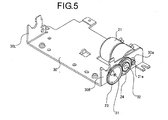
- Fig. 5 is a perspective view of the drive transmission mechanism of a conventional thermal printer. In Fig. 5, a
main frame 30 has substantially a half-rectangular shape consisting of side walls, opposite the direction of the paper width, and a bottom plate. Aninsertion hole 30a is formed in aright side wall 30R in order to insert adrive gear 21a of amotor 21 and to position themotor 21, and beside theinsertion hole 30a, twogear support shafts main frame 30, generally, sheet metal processing is performed using a metallic material, such as steel, to obtain themain frame 30 having a predetermined shape. Therefore, it is difficult to integrally form thegear support shafts main frame 30, and as described above, thegear support shafts - Further,
idler gears motor 21 to the platen roller, are fitted over thegear support shafts main frame 30, and themotor 21 is attached to themain frame 30 by screws and engages theidler gears idler gears motor 21, that are mounted on themain frame 30 in this manner constitute the drive transmission mechanism. Further, there is another thermal printer wherein, although not shown in Fig. 5, a dust cover is provided outside gears to prevent dust from entering the drive transmission mechanism. - Furthermore, as an additional technique related to a drive transmission mechanism for driving a platen roller, the present inventor has proposed thermal printers wherein a housing frame is constituted as a resin frame separable into two upper and lower segments, and wherein a plurality of holding units that freely hold the rotary shafts of a motor and idler gears are formed in the housing frame (see patent documents 1 and 2).
- Patent Document 1:
Japanese Patent Laid-Open Publication No. 2003-237118 - Patent Document 2:
Japanese Patent Laid-Open Publication No. 2003-237121 - According to the structure of the thermal printer in Fig. 5, the
idler gears gear support shafts main frame 30, and engage thedrive gear 21a of themotor 21 and the coupled gear of the platen roller. Therefore, many factors are present that adversely affect the tolerance between gears, and accurate assembly of the drive transmission mechanism is limited. That is, the tolerances for the gears is affected by an inclination that occurs when thegear support shafts motor 21 is positioned by theinsertion hole 30a in themain frame 30, it is not easy to mount themotor 21 very accurately. Therefore, problems would arise in that efficiency of transmission of motor torque is deteriorated and in that durability of the drive transmission mechanism is reduced. - In addition, according to the conventional technique, assembly of the drive transmission mechanism is simplified; however, since a resin frame is employed, durability and heat releasing properties are inferior to those of a steel frame. Therefore, in order to cope with downsizing and increasing output, it can not always be said that this technique is appropriate.
- One objective of the present invention is to provide a printer that employs a platen roller as conveying means, for which the accuracy of the assembly of the constituents of a drive transmission mechanism that drives a platen roller is increased, and the heat releasing function of a motor that is a drive source is also improved, so that downsizing and increasing output can be coped with.
- To achieve this objective, according to the present invention, a printer comprises:
- a platen roller, for conveying a recording sheet,
- a print head, arranged opposite the platen roller,
- a drive unit, for rotating the platen roller, and
- a main frame, including a pair of side walls that can rotatably support the platen roller,
- wherein the drive unit includes: a motor; idler gears, for transmitting a rotational force provided by the motor to the platen roller; and a gear fitting member, integrally formed with gear support shafts that support the idler gears,
- wherein the motor and idler gears are capable of being mounted in the main frame while attached to the gear fitting member, and
- wherein a drive gear of the motor and the idler
- gears are stored in a space defined by the gear fitting member and one of the side walls of the main frame.
- In addition, the gear fitting member is formed of an alloy material by die casting. Specifically, a material having a superior heat release property and an appropriate rigidity is preferable, and as an example, a zinc alloy, a magnesium alloy or a titanium alloy can be employed.
- Further, the motor is attached through a flange member to the gear fitting member, and an engagement groove that is to be fitted in the distal end of the gear shaft is formed in the flange member. Thus, the positioning of a motor is performed by fitting the distal end of the gear shaft into the engagement groove. Further, a thermal head is prepared as printing means.
- A diagram is a perspective view of the printing portion of a thermal printer for which the present invention is applied. Fig. 2 is a perspective view of a main frame, from which all members except for a drive unit have been removed. Fig. 3 is an enlarged perspective view of the drive unit. Fig. 4 is an exploded perspective view of the drive unit. Fig. 5 is a perspective view of a conventional drive transmission mechanism.
- A preferred mode according to the present invention will now be specifically described while referring to the drawings. In this mode, an explanation will be given for a portable thermal printer that is designed to be extended horizontally so as to perform comparatively wide printing, although not especially specified, and that prints, as a recording medium, a recording sheet with release paper such that an adhesive surface is exposed by peeling off the release paper on the reverse side.
- Fig. 1 is a perspective view of the printing portion of a thermal printer for which the present invention is applied. Fig. 2 is a perspective view of a main frame, from which all members other than a drive unit have been removed.
- A
thermal printer 100 according to this mode includes a printing portion constituted by: athermal head 11, wherein a plurality ofheat generating members 11a are horizontally arranged, in a line; a platen roller (not shown), for pressing a sheet against thethermal head 11 and conveying the sheet by rotating; adrive unit 20, for rotating the platen roller through a gear drive mechanism; and amain frame 10, to which the individual members can be attached. - The
main frame 10 is formed of steel, through sheet metal processing, substantially in a half-rectangular shape that is formed by side walls, opposite each other in the direction of sheet width, and a bottom plate. Holder grooves 10a, 10a, for holding the rotary shaft of the platen roller, are provided in left andright walls main frame 10. Also, in the left andright walls head support member 12 securely fitted to the thermal head 11) and alock arm member 13. In addition, screw holes (not shown) for securing the drive unit are formed in theright side wall 10R. - The
lock arm member 13 is formed, entirely in a U shape, andhooks thermal head 11 is securely attached to thehead support member 12 that functions as heat release means, for releasing heat generated by thethermal head 11. A plurality ofcoil springs head support member 12 and thelock arm member 13, and push against these two, so that the two can repel each other. Further, the rear face portion of thethermal head 13 is exposed below the rear face of thehead support member 15, and an FPC (Flexible Print Circuit) 16 is connected at almost the center of the rear face portion of thethermal head 13 that is exposed. Thelock arm member 13 and thethermal head 11 are rotatably supported by the shaft that is inserted through the shaft holes 10b, 10b of themain frame 10. Further, apaper guide 15 is attached in front of thethermal head 11. - With this structure, the arm of the
lock arm member 13 is pulled backward by thecoil springs 14. Thus, the rotary shaft of the platen roller is held in theholder grooves main frame 10 and between thehooks lock arm member 13, and thethermal head 11 is pressed against the platen roller. When an open/close lever 13a, which is arranged in the front portion of the right arm of thelock arm member 13, is pressed, and when thelock arm member 13 is pivoted at the shaft and thehooks 13b are released from the rotary shaft of the platen roller, the platen roller can be detached. - In this mode, the motor and the individual parts of the gear transmission mechanism are not directly mounted on the
main frame 10, but these parts are to be assembled as thedrive unit 20, and thereafter, the assembly is to be attached to themain frame 10. This is one difference from the conventional printer. - While referring to Figs. 3 and 4, a specific explanation will be given for the
drive unit 20 that is secured, by screws, to theright side wall 10R of themain frame 10. Fig. 3 is an enlarged perspective view of the drive unit, and Fig. 4 is an exploded perspective view of the drive unit. - The
drive unit 20 includes: the idler gears 23, 24, for transmitting the rotational force provided by themotor 21 to the platen roller; and thegear fitting member 22, to which the idler gears 23, 24 are to be fitted. - Specifically, the
gear fitting member 22 is made of a zinc alloy by die casting, andgear support shafts gear support shafts gear fitting member 22. And in a state wherein thedrive gear 21a is inserted into astorage portion 22c and engages theidler gear 24, themotor 21 is secured to thegear fitting member 22 by screws (not shown) at two locations. As a result, thedrive unit 20 is provided. At this time, the distal end of thegear support shaft 22b is fitted into anengagement groove 25a that is formed in amotor flange 25 and supports theidler gear 24 and also positions themotor 21. Further, since the motor is closely attached to thegear fitting member 22, heat generated by themotor 21 is released through thegear fitting member 22. Thus, it is preferable that thegear fitting member 22 be formed of a material having a superior heat release property. - When the
drive unit 20 having the above structure is secured, by screws, to theright side wall 10R of themain frame 10, the distal end of thegear support shaft 22a is fitted into the engagement groove formed in themain frame 10 and supports theidler gear 23. Furthermore, when the platen roller is to be attached to themain frame 10 and thelock arm member 13, the coupled gear of the platen roller engages theidler gear 23, so that the rotation force provided by themotor 21 is transmitted to the platen roller. - As described above, since conventionally the gear support shafts are provided for the main frame by forcible insertion, this causes a variation in the inter-shaft distance for the individual gears. However, in this mode, since the
gear support shafts gear fitting member 22 by die casting, the accuracy of the assembly of thedrive gear 21a of the motor, the idler gears 23, 24 and the coupled gear of the platen roller can be improved considerably. Therefore, since the variation in the inter-shaft distance for the gears is removed, the efficiency for the transmission of motor torque is increased, and the durability of the thermal printer is also increased. For example, the durability of the conventional thermal printer was 30 km for the sheet conveying distance, while in this embodiment, the durability was considerably increased to 50 km. - Furthermore, the
drive unit 20, wherein themotor 21 and the idler gears 23, 24 are mounted and positioned on thegear fitting member 22, can be attached to themain frame 10. Thus, the assembly efficiency is considerably improved. Further, since thedrive gear 21a of themotor 21 and the idler gears 23, 24 are stored in the space defined by thegear fitting member 22 and theright side wall 10R of themain frame 10, the entry of dust, etc., will not occur. That is, unlike the conventional case, a dust cover is not required to prevent the entry of dust, and the number of parts can be reduced. - In addition, since the accuracy for the mounting of the parts on the
drive unit 20 can be improved, a predetermined accuracy can be maintained, even though the sizes of parts are reduced, and since the heat releasing function is superior, the downsizing of the printer and the increase in the output can also be coped with. - The invention provided by the present inventor has been specifically explained based on the mode. However, the present invention is not limited to the above described mode, and various modifications are available. For example, in the above mode, a zinc alloy is employed for the material of the
gear fitting member 22. However, a magnesium alloy, a titanium alloy or another alloy that has a superior heat release property and an appropriate rigidity can also be employed. It is preferable that an alloy material be employed while taking heat resistance and heat releasing properties into account. However, thegear fitting member 22 can also be formed of a resin material, and in this case, the effects, such as the improvement of the assembly efficiency, can also be obtained. - According to the invention, since the gear support shafts, for supporting the idler gears, are integrally formed with the gear fitting member, the drive gear of the motor, the idler gears, and the coupled gear of the platen roller can be accurately assembled. Thus, since the variation in the inter-shaft distance between the gears can be removed, the efficiency for the transmission of motor torque can be improved, and energy saving can be provided.
- Furthermore, since the drive unit, wherein the motor and idler gears are attached and positioned on the gear fitting member, can be mounted on the main frame, the assembly efficiency can be considerably increased. In addition, since the drive gear for the motor and the idler gears are stored in the space defined by the gear fitting member and one side wall of the main frame, the dust cover function can be provided without attaching a cover, as in the conventional case, and the number of parts can be reduced. Further, since heat generated by the motor is released through the gear fitting member, the heat releasing efficiency is improved, and the increase in the output can be coped with.
- As described above, since the accuracy of the mounting of the gear transmission mechanism can be improved, a desired accuracy can be maintained even though the sizes of the parts are reduced, and since the heat releasing function is also superior, effects are obtained such that the downsizing of a printer and the increase in the output can be coped with.
- In addition, since the gear fitting member is made of an alloy material by die casting, the gear support shaft can be formed at an extremely high processing accuracy. Further, since as an example, a zinc alloy, a magnesium alloy or a titanium alloy that has a superior heat release property and an appropriate rigidity is employed, heat generated by the motor can be efficiently released, and superior durability is provided.
- Furthermore, the motor is mounted on the gear storage portion though the flange member, and the engagement groove into the distal end of the gear shaft is fitted are formed in the flange member. And since the positioning of the motor is performed by fitting the distal end of the gear shaft into the engagement groove, the accuracy of the assembly of the motor can be improved, and a variation in the inter-shaft distance between the drive gear of the motor and the idle gear can be removed.
- Moreover, the preset invention is especially effective for a thermal printer for which downsizing and an increase in output are requested.
Claims (5)
- A printer, which comprises:a platen roller, for conveying a recording sheet,a print head, arranged opposite the platen roller,a drive unit, for rotating the platen roller, anda main frame, including a pair of side walls that can rotatably support the platen roller, characterized in that:the drive unit includesa motor,idler gears, for transmitting a rotational force provided by the motor to the platen roller, anda gear fitting member, integrally formed with gear support shafts that support the idler gears;the motor and idler gears are capable of being mounted in the main frame while attached to the gear fitting member; anda drive gear of the motor and the idler gears are stored in a space defined by the gear fitting member and one of the side walls of the main frame.
- A printer according to claim 1, characterized in that the gear fitting member is formed of an alloy material by die casting.
- A printer according to claim 2, characterized in that the alloy material is a zinc alloy, a magnesium alloy or a titanium alloy.
- A printer according to one of claims 1 to 3,
characterized in that the motor is attached through a flange member to the gear fitting member, and an engagement groove that is to be fitted in the distal end of the gear shaft is formed in the flange member. - A printer according to one of claims 1 to 4, wherein the print head is a thermal head in which a plurality of heat generating members are arranged in one direction.
Applications Claiming Priority (2)
| Application Number | Priority Date | Filing Date | Title |
|---|---|---|---|
| JP2004052098A JP4421916B2 (en) | 2004-02-26 | 2004-02-26 | Printer device |
| PCT/JP2005/001855 WO2005082634A1 (en) | 2004-02-26 | 2005-02-08 | Printer |
Publications (3)
| Publication Number | Publication Date |
|---|---|
| EP1719628A1 true EP1719628A1 (en) | 2006-11-08 |
| EP1719628A4 EP1719628A4 (en) | 2008-10-15 |
| EP1719628B1 EP1719628B1 (en) | 2009-11-04 |
Family
ID=34908657
Family Applications (1)
| Application Number | Title | Priority Date | Filing Date |
|---|---|---|---|
| EP05709907A Expired - Fee Related EP1719628B1 (en) | 2004-02-26 | 2005-02-08 | Printer |
Country Status (6)
| Country | Link |
|---|---|
| US (1) | US7862247B2 (en) |
| EP (1) | EP1719628B1 (en) |
| JP (1) | JP4421916B2 (en) |
| KR (1) | KR101076532B1 (en) |
| CN (1) | CN100509417C (en) |
| WO (1) | WO2005082634A1 (en) |
Cited By (4)
| Publication number | Priority date | Publication date | Assignee | Title |
|---|---|---|---|---|
| KR100949523B1 (en) | 2007-09-19 | 2010-03-25 | 후지쯔 콤포넌트 가부시끼가이샤 | Printer device |
| US7942595B2 (en) | 2007-04-26 | 2011-05-17 | Kabushiki Kaisha Sato | Gear unit apparatus for printer |
| EP3246169A1 (en) * | 2016-05-16 | 2017-11-22 | Seiko Instruments Inc. | Thermal printer and portable terminal |
| EP3566876A1 (en) * | 2018-05-08 | 2019-11-13 | APS Trading OOD | Compact thermal printing mechanism |
Families Citing this family (7)
| Publication number | Priority date | Publication date | Assignee | Title |
|---|---|---|---|---|
| US8002214B2 (en) * | 2006-03-28 | 2011-08-23 | Seiko Epson Corporation | Rolled medium holding device holding a rolled medium at both ends and a recording apparatus including the rolled medium holding device |
| JP5048432B2 (en) * | 2007-09-19 | 2012-10-17 | 富士通コンポーネント株式会社 | Printer device |
| JP5159244B2 (en) * | 2007-10-24 | 2013-03-06 | シチズン・システムズ株式会社 | Thermal printer |
| JP5081577B2 (en) * | 2007-10-24 | 2012-11-28 | 株式会社リコー | Image forming apparatus |
| JP5671858B2 (en) * | 2010-07-15 | 2015-02-18 | セイコーエプソン株式会社 | Printing apparatus, roll diameter calculation method, and program |
| WO2018020762A1 (en) * | 2016-07-27 | 2018-02-01 | 京セラドキュメントソリューションズ株式会社 | Drive transmission mechanism and image forming device provided with same |
| CN108016150B (en) * | 2017-11-30 | 2020-01-03 | 森大(深圳)技术有限公司 | Feed roll supporting seat and printing equipment with same |
Family Cites Families (14)
| Publication number | Priority date | Publication date | Assignee | Title |
|---|---|---|---|---|
| GB2186342A (en) * | 1986-02-06 | 1987-08-12 | Johnson Electric Ind Mfg | An electric motor and gearbox unit and component parts thereof |
| JPH01145170A (en) * | 1987-11-30 | 1989-06-07 | Nec Home Electron Ltd | Paper feeder |
| JP3124767B2 (en) * | 1989-10-02 | 2001-01-15 | シャープ株式会社 | Paper feeder |
| US5198836A (en) * | 1989-12-11 | 1993-03-30 | Seiko Instruments Inc. | Compact line thermal printer |
| JPH07237324A (en) * | 1994-02-28 | 1995-09-12 | Tamura Seisakusho Co Ltd | Paper feed driver in thermal printer |
| JPH08156350A (en) * | 1994-12-05 | 1996-06-18 | Seiko Epson Corp | Printer |
| JPH0986000A (en) * | 1995-09-27 | 1997-03-31 | Casio Comput Co Ltd | Printing device |
| JP2000094767A (en) * | 1998-09-25 | 2000-04-04 | Fujitsu Takamisawa Component Ltd | Thermal printer |
| ATE303903T1 (en) * | 1999-01-11 | 2005-09-15 | Seiko Epson Corp | POWER TRANSFER SWITCHING DEVICE |
| JP4116733B2 (en) * | 1999-04-26 | 2008-07-09 | 株式会社サトー | Bar code printer |
| WO2002042084A1 (en) * | 2000-11-27 | 2002-05-30 | F & F Limited | Printer |
| JP2003162070A (en) * | 2001-11-27 | 2003-06-06 | Fuji Photo Film Co Ltd | Sheet material holding drum |
| JP2004189384A (en) * | 2002-12-10 | 2004-07-08 | Murata Mach Ltd | Invert carrying unit and image forming apparatus |
| US20050022946A1 (en) * | 2003-07-31 | 2005-02-03 | Douglas Domel | Drive mechanism for motorized window coverings |
-
2004
- 2004-02-26 JP JP2004052098A patent/JP4421916B2/en not_active Expired - Fee Related
-
2005
- 2005-02-08 KR KR1020067016844A patent/KR101076532B1/en active IP Right Grant
- 2005-02-08 US US10/590,587 patent/US7862247B2/en not_active Expired - Fee Related
- 2005-02-08 WO PCT/JP2005/001855 patent/WO2005082634A1/en active Application Filing
- 2005-02-08 CN CNB2005800060247A patent/CN100509417C/en not_active Expired - Fee Related
- 2005-02-08 EP EP05709907A patent/EP1719628B1/en not_active Expired - Fee Related
Non-Patent Citations (2)
| Title |
|---|
| No further relevant documents disclosed * |
| See also references of WO2005082634A1 * |
Cited By (9)
| Publication number | Priority date | Publication date | Assignee | Title |
|---|---|---|---|---|
| US7942595B2 (en) | 2007-04-26 | 2011-05-17 | Kabushiki Kaisha Sato | Gear unit apparatus for printer |
| KR100949523B1 (en) | 2007-09-19 | 2010-03-25 | 후지쯔 콤포넌트 가부시끼가이샤 | Printer device |
| EP2039526A3 (en) * | 2007-09-19 | 2010-12-08 | Fujitsu Takamisawa Component Limited | Printing apparatus |
| US8550733B2 (en) | 2007-09-19 | 2013-10-08 | Fujitsu Component Limited | Printing apparatus with sealed gear drive mechanism |
| EP3246169A1 (en) * | 2016-05-16 | 2017-11-22 | Seiko Instruments Inc. | Thermal printer and portable terminal |
| US10350923B2 (en) | 2016-05-16 | 2019-07-16 | Seiko Instruments Inc. | Thermal printer and portable terminal |
| EP3566876A1 (en) * | 2018-05-08 | 2019-11-13 | APS Trading OOD | Compact thermal printing mechanism |
| WO2019214902A1 (en) * | 2018-05-08 | 2019-11-14 | Aps Trading Ood | Compact thermal printing mechanism |
| US11220113B2 (en) | 2018-05-08 | 2022-01-11 | Aps Trading Ood | Compact thermal printing mechanism |
Also Published As
| Publication number | Publication date |
|---|---|
| CN1922024A (en) | 2007-02-28 |
| CN100509417C (en) | 2009-07-08 |
| KR101076532B1 (en) | 2011-10-24 |
| EP1719628B1 (en) | 2009-11-04 |
| US20080019757A1 (en) | 2008-01-24 |
| EP1719628A4 (en) | 2008-10-15 |
| JP2005238658A (en) | 2005-09-08 |
| KR20060127148A (en) | 2006-12-11 |
| JP4421916B2 (en) | 2010-02-24 |
| US7862247B2 (en) | 2011-01-04 |
| WO2005082634A1 (en) | 2005-09-09 |
Similar Documents
| Publication | Publication Date | Title |
|---|---|---|
| EP1719628B1 (en) | Printer | |
| US8579528B2 (en) | Thermal printer | |
| US7245312B2 (en) | Thermal printer with quick-release printhead assembly | |
| EP1736319B1 (en) | Image generating apparatus | |
| US5746527A (en) | Printing apparatus provided with an auto cutter | |
| JP2008094009A (en) | Printing apparatus | |
| JP4412531B2 (en) | Thermal printer | |
| CN102120389A (en) | Recording device and recording medium supply mechanism for a recording device | |
| JP2006240084A (en) | Cover opening/closing device and recorder having the same | |
| JP2003237118A (en) | Thermal printer | |
| EP1338424B1 (en) | Thermal printer | |
| JP5754222B2 (en) | Printing device | |
| JP5055943B2 (en) | Printing device | |
| JP2000318257A (en) | Line thermal printer | |
| JP2008137319A (en) | Printer driving mechanism | |
| JP2000071587A (en) | Ribbon cartridge and printer apparatus using this | |
| JP2963618B2 (en) | Thermal printer | |
| US8096549B2 (en) | Image generating apparatus | |
| JPH081879Y2 (en) | Mount guide device for label printer | |
| JP4715609B2 (en) | Image forming apparatus | |
| JP2008110484A (en) | Printer | |
| JP2000071497A (en) | Head pressing mechanism for printing apparatus | |
| JP2000072268A (en) | Paper feeding mechanism | |
| JPH10279146A (en) | Take-up mechanism, and printer using same | |
| JP2000072261A (en) | Paper feeding mechanism and sheet cassette employed by the mechanism |
Legal Events
| Date | Code | Title | Description |
|---|---|---|---|
| PUAI | Public reference made under article 153(3) epc to a published international application that has entered the european phase |
Free format text: ORIGINAL CODE: 0009012 |
|
| 17P | Request for examination filed |
Effective date: 20060904 |
|
| AK | Designated contracting states |
Kind code of ref document: A1 Designated state(s): FR IT |
|
| DAX | Request for extension of the european patent (deleted) | ||
| RBV | Designated contracting states (corrected) |
Designated state(s): FR IT |
|
| A4 | Supplementary search report drawn up and despatched |
Effective date: 20080915 |
|
| GRAP | Despatch of communication of intention to grant a patent |
Free format text: ORIGINAL CODE: EPIDOSNIGR1 |
|
| GRAS | Grant fee paid |
Free format text: ORIGINAL CODE: EPIDOSNIGR3 |
|
| GRAA | (expected) grant |
Free format text: ORIGINAL CODE: 0009210 |
|
| AK | Designated contracting states |
Kind code of ref document: B1 Designated state(s): FR IT |
|
| PLBE | No opposition filed within time limit |
Free format text: ORIGINAL CODE: 0009261 |
|
| STAA | Information on the status of an ep patent application or granted ep patent |
Free format text: STATUS: NO OPPOSITION FILED WITHIN TIME LIMIT |
|
| 26N | No opposition filed |
Effective date: 20100805 |
|
| REG | Reference to a national code |
Ref country code: FR Ref legal event code: PLFP Year of fee payment: 12 |
|
| REG | Reference to a national code |
Ref country code: FR Ref legal event code: PLFP Year of fee payment: 13 |
|
| REG | Reference to a national code |
Ref country code: FR Ref legal event code: PLFP Year of fee payment: 14 |
|
| PGFP | Annual fee paid to national office [announced via postgrant information from national office to epo] |
Ref country code: IT Payment date: 20200128 Year of fee payment: 16 |
|
| PGFP | Annual fee paid to national office [announced via postgrant information from national office to epo] |
Ref country code: FR Payment date: 20200113 Year of fee payment: 16 |
|
| PG25 | Lapsed in a contracting state [announced via postgrant information from national office to epo] |
Ref country code: FR Free format text: LAPSE BECAUSE OF NON-PAYMENT OF DUE FEES Effective date: 20210228 |
|
| PG25 | Lapsed in a contracting state [announced via postgrant information from national office to epo] |
Ref country code: IT Free format text: LAPSE BECAUSE OF NON-PAYMENT OF DUE FEES Effective date: 20210208 |