EP1719434A2 - System for moving fitments in a piece of furniture - Google Patents
System for moving fitments in a piece of furniture Download PDFInfo
- Publication number
- EP1719434A2 EP1719434A2 EP06009022A EP06009022A EP1719434A2 EP 1719434 A2 EP1719434 A2 EP 1719434A2 EP 06009022 A EP06009022 A EP 06009022A EP 06009022 A EP06009022 A EP 06009022A EP 1719434 A2 EP1719434 A2 EP 1719434A2
- Authority
- EP
- European Patent Office
- Prior art keywords
- fitment
- space
- base body
- guiding
- vertical
- Prior art date
- Legal status (The legal status is an assumption and is not a legal conclusion. Google has not performed a legal analysis and makes no representation as to the accuracy of the status listed.)
- Withdrawn
Links
Images

Classifications
-
- A—HUMAN NECESSITIES
- A47—FURNITURE; DOMESTIC ARTICLES OR APPLIANCES; COFFEE MILLS; SPICE MILLS; SUCTION CLEANERS IN GENERAL
- A47B—TABLES; DESKS; OFFICE FURNITURE; CABINETS; DRAWERS; GENERAL DETAILS OF FURNITURE
- A47B96/00—Details of cabinets, racks or shelf units not covered by a single one of groups A47B43/00 - A47B95/00; General details of furniture
- A47B96/16—Drawers or movable shelves coupled to doors
-
- A—HUMAN NECESSITIES
- A47—FURNITURE; DOMESTIC ARTICLES OR APPLIANCES; COFFEE MILLS; SPICE MILLS; SUCTION CLEANERS IN GENERAL
- A47B—TABLES; DESKS; OFFICE FURNITURE; CABINETS; DRAWERS; GENERAL DETAILS OF FURNITURE
- A47B81/00—Cabinets or racks specially adapted for other particular purposes, e.g. for storing guns or skis
- A47B81/002—Corner cabinets; Cabinets designed for being placed in a corner or a niche
-
- A—HUMAN NECESSITIES
- A47—FURNITURE; DOMESTIC ARTICLES OR APPLIANCES; COFFEE MILLS; SPICE MILLS; SUCTION CLEANERS IN GENERAL
- A47B—TABLES; DESKS; OFFICE FURNITURE; CABINETS; DRAWERS; GENERAL DETAILS OF FURNITURE
- A47B2210/00—General construction of drawers, guides and guide devices
- A47B2210/05—Metal wire baskets for vertical drawers
-
- A—HUMAN NECESSITIES
- A47—FURNITURE; DOMESTIC ARTICLES OR APPLIANCES; COFFEE MILLS; SPICE MILLS; SUCTION CLEANERS IN GENERAL
- A47B—TABLES; DESKS; OFFICE FURNITURE; CABINETS; DRAWERS; GENERAL DETAILS OF FURNITURE
- A47B88/00—Drawers for tables, cabinets or like furniture; Guides for drawers
- A47B88/40—Sliding drawers; Slides or guides therefor
- A47B88/42—Vertically-oriented drawers, i.e. drawers where the height exceeds the width
Landscapes
- Drawers Of Furniture (AREA)
- Hinges (AREA)
Abstract
a first, closing position (I), in which the outer and inner fitments (Ue, Ui) are situated inside the base body (1), respectively in a first space (S1) and in a second space (S2);
an intermediate position (M), in which the inner fitment (Ui) remains in the second space (S2) and the outer fitment (Ue) is removed from base body (1), to free the first space (S1);
a second position (O), in which the outer fitment (Ue) is rotated outwards and the inner fitment (Ui) is moved longitudinally to occupy the first space (S1) and free the second space (S2).
Description
- The present invention relates to the technical field concerning the moving fitments in a piece of furniture, e.g. an angle-shaped element.
-
- The outer and inner fitments are connected by levers, which allow the inner built-in fitment to be moved toward or away from the free space, while the outer fitment, mounted on a rotating guide, is removed from the basic unit in a position corresponding to its front face and rotated by at least 90° with respect to a vertical axis.
- The outer and inner fitment include: a flat sliding frame, arranged vertically; a plurality of baskets, suspended on one side on respective flat sliding frames, extending horizontally from the frames.
- Moreover, the sliding frame of the inner fitment is removably mounted on a flat, stationary guide frame.
- The piece of furniture described in the above document has disadvantages deriving from the assembling of its parts.
- The positioning of the flat and stationary guide frame, of the inner fitment and the connecting of the two fitments by levers, must be performed precisely by skilled operators, so as not to put at risk the correct motion, which affects negatively the assembling time and costs.
- The object of the present invention is to propose a system for moving fitments in an angle-shaped piece of furniture, which allows its easy and rapid assembling.
- Another object of the present invention is to propose a system obtained by elements, which can be assembled also by not particularly skilled operators.
- A further object of the present invention is to propose a system of a simple concept and obtained at low cost.
- The above mentioned objects are obtained by the present invention, as it is understood from the claims.
- The characteristic features of the invention are pointed out with reference to the enclosed Figures, in which:
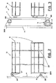
- Figure 1 is a schematic, top view of a first embodiment of a system for moving fitments in a piece of furniture, proposed by the present invention, with a first position of the fitment of said piece of furniture pointed out;
- Figure 2 is an enlarged section view, taken along the II - II of Figure 1;
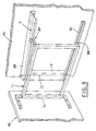
- Figure 3 is an enlarged section view, taken along the III - III of Figure1;
- Figure 4 is the same view as Figure 1, with an intermediate position of the fitments of the piece of furniture pointed out;
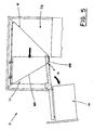
- Figure 5 is the same view as Figure 1, with a second position of the fitments of the piece of furniture pointed out;
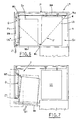
- Figure 6 is a schematic, top view of a second embodiment of the system for moving fitments in a piece of furniture, with a first position of the fitments of said piece of furniture pointed out;
- Figure 7 is the same view as Figure 6, with an initial movement of a fitment of the piece of furniture pointed out;
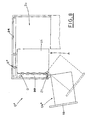
- Figure 8 is the same view as Figure 6, with a second position of the fitment of the piece of furniture pointed out;
- Figure 9 is an enlarged, schematic and prospective view of the detail Y of Figure 7, pointing out a subsequent position, with respect to Figure 7.
- The enclosed Figures show a system for moving fitments in a piece of furniture, e.g. angle shaped.
- According to a first embodiment, shown in Figures 1, 2, 3, 4, 5, the system includes: a
base body 1, whose inner, rear, vertical wall P carries, longitudinally fastened thereto, known guiding means, e.g. alower track 23 and anupper track 24, to whose inner, transverse, vertical wall Pt, the lower part of a guiding arm B is articulated, rotating with respect to a vertical axis Z. - A
stationary guide 300 is fastened to the upper part of the wall Pt, as shown in Figure 3. - The
base body 1 has a first space S1, delimited thereinside, near its opening A, and a second inner space S2, adjacent to the first space S1. - There are two built-in fitments, an outer fitment Ue and an inner fitment Ui.
- The outer fitment Ue (Figure 3) includes a vertical frame T, on which
baskets 3, e.g. two, are suspended. - The vertical frame T has guiding
elements 30 of known type, whose lower part couple telescopically with the rotating guiding arm B and whose upper part couples with thestationary guide 300. - The inner fitment Ui (Figure 2) includes
containers 2, e.g. two, mutually connected byvertical uprights 22 and carrying known guiding and/or rolling means R, R*. - For example, the first guiding means R are defined by a roll having a horizontal axis and the second guiding means R* include rolls having vertical axis, guided respectively in the
lower track 23 and theupper track 24. - The inner fitment Ui carries, fastened thereto, connecting
elements 200, e.g. as shown in Figure 2, brackets fixed to thelower container 2. - The outer fitment Ue and the inner fitment Ui are connected by connecting means F, including a
cable 4, which is set loop-like on threeidle elements base body 1. - The
cable 4 is fastened to the connectingelements 200 of the inner fitment Ui and fixed in a point K to the rotating guiding arm B, to define anupstream branch 40 and adownstream branch 49. - The connecting means F include also tension means 6 of known type, e.g. coaxial springs or outer tension devices, fastened to the
base body 1, so as to act on thecable 4 in order to keep it taut. - The outer fitment Ue and the inner fitment Ui take:
- a first, closing position I (Figure 1), in which the outer fitment Ue is situated within the first space S1 and the inner fitment Ui within the second space S2;
- an intermediate position M (Figure 4), in which the inner fitment Ui remains in the second space S2 and the outer fitment Ue is removed from the
base body 1, to let the first space S1 free; - a second position O (Figure 5), in which the outer fitment Ue is rotated on the vertical axis Z outwards and the inner fitment Ui is moved longitudinally to occupy the first space S1 and let the second space S2 free.
- If a user is going to use only the outer fitment Ue, to remove or place things in the
baskets 3, he/she must determine the passage from the first position I to the intermediate position M. - The user pulls the outer fitment Ue outwards, in the direction indicated with the arrow J (Figure 4), making the guiding
elements 30 slide in the guiding arm B and in thestationary guide 300, until the outer fitment Ue is removed from the first space S1, thus making thebaskets 3 accessible. - If the user needs to use the
containers 2 of the inner fitment Ui, he/she must first place the outer fitment Ue in the intermediate position M, and then rotate it in the direction of the arrow W (Figure 5). - Before the above rotation, the
guiding elements 30, sliding in thestationary guide 300, are removed from the latter and the guiding arm B rotates on the vertical axis Z, which consequently draws theupstream branch 40 of thecable 4 to make the inner fitment Ui move longitudinally, so as to free the second space S2 and occupy the first space S1, thus making thecontainers 2 accessible. - After having used the
containers 2, the user must restore the first closing position I, therefore he/she must make the guiding arm B rotate in the direction opposite to the arrow W, bring the outer fitment Ue back to the intermediate position M and then push it inwards, in the direction opposite to the arrow J. - The above movements make the lower part of the guiding
elements 30 slide in the guiding arm B and the upper part thereof enter and slide in thestationary guide 300, which causes the pulling of thedownstream branch 49 of thecable 4, thus making the inner fitment Ui move longitudinally, so as to let the first space S1 free and occupy the second space S2, to allow the outer fitment Ue enter again the first space S1. - According to a second embodiment, shown in Figures 6, 7, 8, 9, the upper part of the inner, transverse, vertical wall Pt of the base body 1 (Figure 9), carries fastened thereto, a
stationary guide 39, in which a shaped path G is made, and the lower part of the same wall Pt carries, articulated thereto, a guiding arm B1, rotating on a vertical axis Z1. - The axis Z1 is contained in a vertical upright V, which is integral with the guiding arm B1 and which extends upwards up to the
stationary guide 39. - The outer fitment Ue*, obtained according to the second embodiment (Figure 9), includes a vertical frame T1, whose outer upright carries, fastened thereto, a
door 10 of the piece of furniture. - The baskets, not shown, are suspended on the frame T1, which has first and second guiding
elements elements 38 couple telescopically with the rotating guiding arm B1 and the second guidingelements 37 couple with thestationary guide 39, so as to enter the shaped guiding path G. - The inner fitment Ui, like the one described in the first embodiment, and the outer fitment Ue* are connected by the same connecting means F (Figure 6), as described previously, with reference to the first embodiment.
- The outer fitment Ue* and the inner fitment Ui take: a first closing position I* (Figure 6), in which the outer fitment Ue* is situated in the first space S1 and the inner fitment Ui in the second space S2; a second position O* (Figure 8), in which the outer fitment Ue* is rotated outwards on the vertical axis Z1, to free the first space S1 and the inner fitment Ui is moved longitudinally to occupy the first space S1 and to free the second space S2.
- If a user wants to use the outer fitment Ue* and/or the inner fitment Ui to take or place things from or in the
baskets 3 and/orcontainers 2, he/she must pull the outer fitment Ue* outwards, in the direction of the arrow J1 (Figure 6), which causes the sliding of the first guidingelements 38 in the guiding arm B and of the second guidingelements 37 in the shaped path G of thestationary guide 39, so as to define initially the oblique movement outwards of the outer fitment Ue* (Figure 7). - The guiding arm B1 rotates, in step relation with the sliding of the first and second guiding
elements - The rotation of the guiding arm B1 causes the subsequent activation, as already described with reference to the first embodiment, of the connecting means F, which make the inner fitment Ui move longitudinally, to free the second space S2 and occupy the first space S1.
- After having used the
baskets 3 and/or thecontainers 2, the user must resume the first closing position I*, therefore he/she must make the guiding arm B1 rotate in the direction opposite to the arrow W1 and push the outer fitment Ue* inwards, in the direction opposite to the arrow J1. - The above movements make the first and second guiding
elements stationary guide 39, which causes the pulling of the downstream branch of thecable 4, thus making the inner fitment Ui move longitudinally, so as to free the first space S1 and occupy the second space S2, and to allow the outer fitment Ue* enter again the first space S1. - The system for moving fitments in a piece of furniture proposed by the present invention includes advantageously the connecting means F, including a
cable 4, which is mounted loop-like on thepulleys base body 1 by any operator, which results in a considerable reduction of assembling time and costs. - The tension means 6, associated to the connecting means F, allow the
cable 4 to maintain the initial tautness in all the intermediate positions of the passage of the outer fitments Ue, Ue* and the inner fitment Ui from the first position I, I*, to the second position O, O*, and vice versa. - The combination of the guiding means 23, 24, the guiding arm B, B1, the
stationary guide - In case of damage of the cable and/or wear of the pulleys, the simplicity of the connecting means F facilitates the rapid and cheap substitution of the cable and/or the pulleys.
- The above described system for moving fitments is particularly advantageous because of its adaptability to pieces of furniture of different dimensions, since the
pulleys cable 4 have suitable dimensions, in relation to the length of thebase body 1. - In the second embodiment (Figures 6 - 9), the oblique movement of the
door 10 avoids interference with parts of elements adjacent to the piece of furniture involved.
Claims (12)
- System for moving fitments in a piece of furniture including: a base body (1), having guiding means (23, 24), fastened to the rear, vertical, inner wall (P) of the base body (1), and at least one guiding arm (B), rotating with respect to a vertical axis (Z) and articulated to the transverse, vertical, inner wall (Pt) of said base body (1); two built-in units, outer (Ue) and inner (Ui), sliding respectively in said guiding arm (B) in said guiding means (23, 24), said units being mutually connected by connecting means (F), so as to take: a first, closing position (I), in which said outer and inner fitments (Ue, Ui) are situated inside said base body (1), respectively in a first space (S1) and in a second space (S2); an intermediate position (M), in which said inner fitment (Ui) remains in said second space (S2) and said outer fitment (Ue) is removed from base body (1), to free said first space (S1); a second position (O), in which said outer fitment (Ue) is rotated outwards and said inner fitment (Ui) is moved longitudinally to occupy said first space (S1) and free said second space (S2), characterized in that said connecting means (F) include a cable (4), mounted loop-like on at least three idle elements (5a, 5b, 5c) and fastened to connecting elements (200), situated in said inner fitment (Ui), and fixed to said guiding arm (B) in an anchoring point (K), to define, on said cable, an upstream branch (40) and a downstream branch (49), with said upstream branch (40) being pulled, so as to move said inner fitment (Ui), during the passage from the intermediate position (M) to said second position (O), forward in order to occupy said first space (S1), and with said downstream branch (49) being pulled, so as to move back said inner fitment (Ui), during the passage from said second position (O) to said intermediate position (M), toward the second space (S2) and to free said first space (S1).
- System for moving fitments in a piece of furniture including: a base body (1), having guiding means (23, 24), fastened to the rear, vertical, inner wall (P) of the base body (1), and a guiding arm (B1), rotating with respect to a vertical axis (Z1) and articulated to the transverse, vertical, inner wall (Pt) of said base body (1) and a stationary guide (39), fastened to said vertical, inner wall (Pt); an outer built-in unit (Ue), sliding in said guiding arm (B1) and said stationary guide (39), and a built-in inner fitment (Ui), sliding in said guiding means (23, 24), said units being mutually connected by connecting means (F), so as to assume: a first, closing position (I*), in which said outer and inner fitments (Ue*, Ui) are situated inside said base body (1), respectively in a first space (S1) and in a second space (S2); a second position (O*), in which said outer fitment (Ue*) is removed from the first space (S1) and rotated outwards and said inner fitment (Ui) is moved longitudinally to occupy said first space (S1) and free said second space (S2), characterized in that said connecting means (F) include a cable (4), mounted loop-like on at least three idle elements (5a, 5b, 5c) and fastened to connecting means, situated in said inner fitment (Ui), and fixed to said guiding arm (B1) in an anchoring point (K), to define, on said cable, an upstream branch and a downstream branch, with said upstream branch being pulled, so as to move said inner fitment (Ui), during the passage from the first position (I*) to the second position (O*), forward in order to occupy said first space (S1), and with said downstream branch being pulled, so as to move back said inner fitment (Ui), during the passage from the second position (O*) to the first position (I*), toward the second space (S2) and to free said first space (S1).
- System, according to claim 1, characterized in that it includes tension means (6), connected to the base body (1), so as to act on the cable (4) in order to keep it taut in all the intermediate positions, during the passage of said outer and inner fitments (Ue, Ui) from the intermediate position (M) to the second position (O), and vice-versa.
- System, according to claim 2, characterized in that it includes tension means, connected to the base body (1), so as to act on the cable (4) in order to keep it taut in all the intermediate positions, during the passage of said outer and inner fitments (Ue*, Ui) from the first position (I*) to the second position (O*), and vice-versa.
- System, according to claim 1 or 2, characterized in that at least said inner fitment (Ui) includes containers (2), mutually connected by vertical uprights (22), carrying guiding and/or rolling means (R, R*), coupled with said guiding means (23, 24).
- System, according to claim 1, characterized in that said outer fitment (Ue) includes a vertical frame (T), which carries, suspended thereon, baskets (3), and which has guiding means (30), coupling telescopically with said guiding arm (B).
- System, according to claim 1, characterized in that said outer fitment (Ue) includes a vertical frame (T), which carries stable baskets (3), suspended thereon, and which has guiding means (30), whose lower part couple telescopically with said guiding arm (B) and whose upper part couple with a stationary guide (300), fastened to the transverse, vertical, inner wall (Pt) of said base body (1), above the position of said guiding arm (B), and in that, in the second position (O), said guiding elements (30), connected to the stationary guide (300) are removed from the latter.
- System, according to claim 2, characterized in that said outer fitment (Ue*) includes a vertical frame (T1), which carries stable baskets, suspended thereon, and which has first guiding means (38), which couple telescopically with said guiding arm (B1); second guiding means (37), guided in a shaped path (G), made in said stationary guide (39), and in that said shaped path (G) determines initially the oblique outward movement of said outer fitment (Ue*), during the passage from the second position (I*) to the second position (O*).
- System, according to claim 1 or 2, characterized in that said connecting elements (200) of the inner fitment (Ui) include brackets fixed to the lower container (2).
- System, according to claim 1 or 2, characterized in that said connecting elements (F) are situated on the bottom of said base body (1).
- System, according to claim 1 or 2, characterized in that said connecting elements (F) are situated on the top of said base body (1).
- System for moving fitments in a piece of furniture including: a base body (1), having guiding means (23, 24), fastened to the rear, vertical, inner wall (P) of the base body (1), and at least one guiding arm (B), rotating with respect to a vertical axis (Z) and articulated to the transverse, vertical, inner wall (Pt) of said base body (1); two built-in units, outer (Ue) and inner (Ui), sliding respectively in said guiding arm (B) in said guiding means (23, 24), said units being mutually connected by connecting means (F), so as to assume: a first, closing position (I), in which said outer and inner fitments (Ue, Ui) are situated inside said base body (1), respectively in a first space (S1) and in a second space (S2); an intermediate position (M), in which said inner fitment (Ui) remains in said second space (S2) and said outer fitment (Ue) is removed from base body (1), to free said first space (S1); a second position (O), in which said outer fitment (Ue) is rotated outwards and said inner fitment (Ui) is moved longitudinally to occupy said first space (S1) and free said second space (S2), characterized in that at least said inner fitment (Ui) includes containers (2), mutually connected by vertical uprights (22), and carrying guiding and/or rolling means (R, R*), coupled with said guiding means (23, 24).
Applications Claiming Priority (1)
| Application Number | Priority Date | Filing Date | Title |
|---|---|---|---|
| IT000305A ITBO20050305A1 (en) | 2005-05-03 | 2005-05-03 | SYSTEM FOR HANDLING OF UNITS IN A MOBILE ELEMENT |
Publications (2)
| Publication Number | Publication Date |
|---|---|
| EP1719434A2 true EP1719434A2 (en) | 2006-11-08 |
| EP1719434A3 EP1719434A3 (en) | 2007-01-17 |
Family
ID=36888975
Family Applications (1)
| Application Number | Title | Priority Date | Filing Date |
|---|---|---|---|
| EP06009022A Withdrawn EP1719434A3 (en) | 2005-05-03 | 2006-05-02 | System for moving fitments in a piece of furniture |
Country Status (2)
| Country | Link |
|---|---|
| EP (1) | EP1719434A3 (en) |
| IT (1) | ITBO20050305A1 (en) |
Cited By (2)
| Publication number | Priority date | Publication date | Assignee | Title |
|---|---|---|---|---|
| EP1961677A1 (en) * | 2007-02-23 | 2008-08-27 | VIBO S.p.A. | Container means |
| EP1974631A1 (en) * | 2007-03-24 | 2008-10-01 | Vauth-Sagel Holding GmbH & Co. KG | Extending fittings for a cupboard with an angled front |
Citations (1)
| Publication number | Priority date | Publication date | Assignee | Title |
|---|---|---|---|---|
| EP0441919A1 (en) | 1989-09-04 | 1991-08-21 | Pekametall Ag | Furniture unit for installation in a right-angled corner of a room. |
Family Cites Families (3)
| Publication number | Priority date | Publication date | Assignee | Title |
|---|---|---|---|---|
| US5127721A (en) * | 1991-03-05 | 1992-07-07 | Michael Inden | Retractable storage system for confined spaces |
| DE29903410U1 (en) * | 1999-02-15 | 1999-08-12 | Yang Oni | Storage device |
| EP1050246B1 (en) * | 1999-05-05 | 2005-06-15 | Peka-Metall Ag | Cupboard |
-
2005
- 2005-05-03 IT IT000305A patent/ITBO20050305A1/en unknown
-
2006
- 2006-05-02 EP EP06009022A patent/EP1719434A3/en not_active Withdrawn
Patent Citations (1)
| Publication number | Priority date | Publication date | Assignee | Title |
|---|---|---|---|---|
| EP0441919A1 (en) | 1989-09-04 | 1991-08-21 | Pekametall Ag | Furniture unit for installation in a right-angled corner of a room. |
Cited By (3)
| Publication number | Priority date | Publication date | Assignee | Title |
|---|---|---|---|---|
| EP1961677A1 (en) * | 2007-02-23 | 2008-08-27 | VIBO S.p.A. | Container means |
| EP1974631A1 (en) * | 2007-03-24 | 2008-10-01 | Vauth-Sagel Holding GmbH & Co. KG | Extending fittings for a cupboard with an angled front |
| WO2008116577A1 (en) * | 2007-03-24 | 2008-10-02 | Vauth-Sagel Holding Gmbh & Co. Kg | Extension brace for a cabinet with an angled front |
Also Published As
| Publication number | Publication date |
|---|---|
| EP1719434A3 (en) | 2007-01-17 |
| ITBO20050305A1 (en) | 2005-08-02 |
Similar Documents
| Publication | Publication Date | Title |
|---|---|---|
| TWI461163B (en) | Device for opening and closing a movable part of a furniture unit | |
| EP2032791B1 (en) | Cabinet or similar article of furniture with a sliding foldaway door | |
| US4729612A (en) | Hinge support system | |
| KR20060107870A (en) | Picking out device of drawer type | |
| EP3346882B1 (en) | Dispensing device | |
| TWI612920B (en) | A retraction device for furniture parts | |
| EP2930112A1 (en) | A table arrangement | |
| US20180128032A1 (en) | Piece of Furniture, in Particular a Cabinet Unit | |
| EP2722460B1 (en) | Extensible roller-type pergola comprising electronic locking means in the end position | |
| CN108086842A (en) | A kind of adjustable lazy-tongs for furniture push-and-pull opening and closing | |
| KR20100122459A (en) | Cupboard unit with extensible pull-out element | |
| WO2014148977A1 (en) | Method and device for a height adjustable cabinet interior | |
| EP1719434A2 (en) | System for moving fitments in a piece of furniture | |
| CN204552402U (en) | The equipment of furniture and the furniture lid for moving furniture | |
| EP3254586A1 (en) | Furniture piece comprising a sliding and lifting mechanism of a shelf | |
| EP2881029A1 (en) | Built-in domestic appliance with decorative panel applied to the door | |
| CN201864258U (en) | Opening-door type garbage bin | |
| CN108368719A (en) | Lifting system for sliding flabellum | |
| KR101623044B1 (en) | Semi-automatic Opening and Closing Device of Sliding Door | |
| KR101654922B1 (en) | Semi-automatic Opening and Closing Device of Sliding Door | |
| EP1359826B1 (en) | Storage apparatus | |
| CN208875667U (en) | A kind of corner pull-basket structure | |
| KR100384083B1 (en) | Furnishing element | |
| JPH04208632A (en) | Front window opening/closing device of cabin for construction machine | |
| DE102008040609A1 (en) | Cooling device i.e. household cooling device, for cooling and/or freezing foods, has door having degree of freedom in addition to translation degree of freedom, and trays having degree of freedom in addition to translation degree of freedom |
Legal Events
| Date | Code | Title | Description |
|---|---|---|---|
| PUAI | Public reference made under article 153(3) epc to a published international application that has entered the european phase |
Free format text: ORIGINAL CODE: 0009012 |
|
| AK | Designated contracting states |
Kind code of ref document: A2 Designated state(s): AT BE BG CH CY CZ DE DK EE ES FI FR GB GR HU IE IS IT LI LT LU LV MC NL PL PT RO SE SI SK TR |
|
| AX | Request for extension of the european patent |
Extension state: AL BA HR MK YU |
|
| PUAL | Search report despatched |
Free format text: ORIGINAL CODE: 0009013 |
|
| AK | Designated contracting states |
Kind code of ref document: A3 Designated state(s): AT BE BG CH CY CZ DE DK EE ES FI FR GB GR HU IE IS IT LI LT LU LV MC NL PL PT RO SE SI SK TR |
|
| AX | Request for extension of the european patent |
Extension state: AL BA HR MK YU |
|
| AKX | Designation fees paid | ||
| REG | Reference to a national code |
Ref country code: DE Ref legal event code: 8566 |
|
| STAA | Information on the status of an ep patent application or granted ep patent |
Free format text: STATUS: THE APPLICATION IS DEEMED TO BE WITHDRAWN |
|
| 18D | Application deemed to be withdrawn |
Effective date: 20070718 |