EP1717070A2 - Ventilation device, in particular for a motor vehicle - Google Patents
Ventilation device, in particular for a motor vehicle Download PDFInfo
- Publication number
- EP1717070A2 EP1717070A2 EP06007106A EP06007106A EP1717070A2 EP 1717070 A2 EP1717070 A2 EP 1717070A2 EP 06007106 A EP06007106 A EP 06007106A EP 06007106 A EP06007106 A EP 06007106A EP 1717070 A2 EP1717070 A2 EP 1717070A2
- Authority
- EP
- European Patent Office
- Prior art keywords
- air
- ventilation device
- louvers
- ducts
- filter
- Prior art date
- Legal status (The legal status is an assumption and is not a legal conclusion. Google has not performed a legal analysis and makes no representation as to the accuracy of the status listed.)
- Granted
Links
Images


Classifications
-
- B—PERFORMING OPERATIONS; TRANSPORTING
- B60—VEHICLES IN GENERAL
- B60H—ARRANGEMENTS OF HEATING, COOLING, VENTILATING OR OTHER AIR-TREATING DEVICES SPECIALLY ADAPTED FOR PASSENGER OR GOODS SPACES OF VEHICLES
- B60H1/00—Heating, cooling or ventilating [HVAC] devices
- B60H1/00642—Control systems or circuits; Control members or indication devices for heating, cooling or ventilating devices
- B60H1/00814—Control systems or circuits characterised by their output, for controlling particular components of the heating, cooling or ventilating installation
- B60H1/00821—Control systems or circuits characterised by their output, for controlling particular components of the heating, cooling or ventilating installation the components being ventilating, air admitting or air distributing devices
- B60H1/00835—Damper doors, e.g. position control
- B60H1/00849—Damper doors, e.g. position control for selectively commanding the induction of outside or inside air
-
- B—PERFORMING OPERATIONS; TRANSPORTING
- B60—VEHICLES IN GENERAL
- B60H—ARRANGEMENTS OF HEATING, COOLING, VENTILATING OR OTHER AIR-TREATING DEVICES SPECIALLY ADAPTED FOR PASSENGER OR GOODS SPACES OF VEHICLES
- B60H3/00—Other air-treating devices
- B60H3/06—Filtering
- B60H3/0608—Filter arrangements in the air stream
- B60H3/0641—Filter arrangements in the air stream near ventilating openings in the vehicle exterior
Definitions
- the invention relates to a ventilation device according to the preamble of claim 1.
- the centrifugal fan is arranged centrally between two such control flaps, wherein the control flaps have parallel axes and are operated in opposite directions.
- the flow of fresh and recirculated air takes place from opposite directions, with a deflection by 90 ° in the spiral housing into it.
- a ventilation device still leaves something to be desired.
- a not designed symmetrically to the longitudinal axis damper, which can be used in such a ventilation device is, for example, in the DE 100 53 814 A1 described.
- a device for the heating, ventilation and / or air conditioning of a vehicle interior is known, with an air blower which sucks controlled by wing flaps air from the vehicle interior and / or from the environment.
- air blowers and a manifold which includes a heat exchanger for heating the air admitted into the manifold and is provided with air outlets to introduce cold or hot air in different areas of the vehicle interior, arranged vertically one above the other, wherein an air supply duct is provided which extends in an approximately vertical direction and is connected at the top with an opening for the supply of air from the environment and at the bottom with the air inlet of the air blower.
- two recirculation air inlets are provided, which open from the side into the air supply duct, controlled by two wing flaps whose pivot axes are arranged on the air duct outside above the recirculation air inlets.
- a ventilation device is provided with at least one intake fan, at least two air ducts controlled by at least one common air flap, through which air, in particular fresh air and / or recirculated air, can reach the intake fan, and at least one filter arranged between air dampers and intake fan, wherein two air dampers are provided are, which preferably control the air flows from three air ducts, the pivot axes of the louvers adjacent and parallel to the air inlet surface of the filter and are arranged parallel to each other, and the louvers extend from the pivot axes of at least partially in the direction of the air ducts.
- This arrangement of the filter is particularly advantageous in trucks, since in this case often the suction fan between the front wall and front hood of the vehicle is arranged, which often leads to design problems that make the ventilation device more expensive.
- the arrangement of exactly one filter, which is arranged in front of the suction fan the number of filters can be minimized.
- the air damper (s) can be minimized in this respect, the cost.
- the flow cross section in the region of the filter (and the adjoining region) is greater than the free flow cross section of the feeding air channels when the louvers completely close one or more of the air channels.
- the air flaps are preferably cylinder flaps or corresponding flaps with an at least partially arcuate cross section perpendicular to the pivot axis. These louvers are particularly well suited to control two airflows coming from different directions, optimally diverting the airflows and distributing them to a wider flow area.
- the flaps on one or both sides, but particularly preferably on the side which is adjacent to the other flap have an outwardly projecting edge or leg, which increases the flap surface, which is particularly advantageous in connection with a cross-sectional enlargement of the air channels in the corresponding area.
- the edge or leg preferably extends in the radial direction to the outside.
- an edge is arranged on the flap side, which is adjacent to the other flap. If edges are formed on both sides of the flap, then the edge on the flap side, which is adjacent to the other flap, is preferably made larger. However, other embodiments are also possible.
- an asymmetrical design of the individual flaps may be useful for acoustic reasons.
- An asymmetric design is also suitable for narrow spaces, since the louvers can be very small in width.
- the individual flaps can also be designed differently, for example, the edges or legs can be designed to have different lengths, to allow optimum adaptation to the given Bauraurntechnik and air channel dimensions, in particular the side channels.
- the ventilation device is formed in mirror image with respect to a median plane, i. E. the two flaps are formed in this particularly preferred case also mirror images with respect to the median plane.
- the filter length preferably corresponds to the length of both louvers (including a possibly present, outwardly, in particular radially projecting edge or leg) on the side, which are adjacent to the filter, in the position in which the two louvers furthest apart are arranged, plus the distance the pivot axes of the louvers +/- 10%, in particular +/- 5% and ideally approximately exactly, so that the entire filter length is traversed as uniformly as possible without special deflection or covering measures and thus can be fully utilized.
- the two louvers preferably regulate the air flows through three air ducts, wherein the air flow through two of the air ducts, preferably the recirculation ducts, is opposite to each other, and the air flow through the third of the air ducts, preferably the fresh air duct, directed perpendicular thereto.
- the fresh air is supplied through the lateral ducts and the circulating air via the central air duct, so that spray water can not get into the ventilating device.
- a ventilation device 1 according to the invention for a truck is described in more detail with reference to Figures 1 to 3, which is arranged between the front wall and the front hood of the vehicle, where the ventilation device 1 is relatively easily accessible, so that replacement work can be carried out quickly.
- the ventilation device 1 has a housing 2, which forms two fan-side ends of circulating air ducts 3 and a fan-side end of a short fresh air duct 4, and a filter 5 and two intake fan 6 together with their volute casing, impellers and their centrally located between the electric drive motor receives.
- a housing 2 which forms two fan-side ends of circulating air ducts 3 and a fan-side end of a short fresh air duct 4, and a filter 5 and two intake fan 6 together with their volute casing, impellers and their centrally located between the electric drive motor receives.
- a common end portion 7 of the circulating air ducts 3 and 4 of the fresh air duct 4 designed as a cylinder flaps damper 8.
- the louvers 8 have a quarter-Hahlzylindrisch trained shut-off surface 9, two perpendicular to the pivot axis at the respective ends of the shut-9 arranged side walls 10 and at both parallel to the pivot axis S ends of the shut-off 9 a radially outwardly projecting edge 11 which extending also outwardly extending over the side walls 10 (see Fig. 1).
- the edge 11 is presently widened on the mutually facing side of the two louvers 8, so that with limited space height in the direction the Umluftkanalford and relatively large fresh air duct width, connected to a relatively large filter length L
- any flap shapes are possible, for example, such as in the DE 100 53 814 A1 are described, but preferably but not necessarily without air guide.
- the pivot axes S of the louvers 8 are arranged parallel to each other according to the embodiment, wherein each pivot axis S present is arranged approximately centrally with respect to the subsequently arranged suction fan 2.
- each pivot axis S present is arranged approximately centrally with respect to the subsequently arranged suction fan 2.
- the pivot axis S respectively arranged approximately in extension of the lateral wall of the fresh air duct 4.
- louvers 8 completely close one of the circulating air ducts 3 in their one end position (cf., FIGS. 1 and 2) and thus substantially the entire common end region 7, through which air drawn in by the fresh air duct 4 is flowed through by the intake blower 6 Filter 5 due to the inner flap shape evenly distributed over the entire filter length L and filter width B flows through the filter 5.
- the edge ends are arranged in shock, but other, for example, overlapping arrangements are possible or it can Bridge be provided in the air duct, against which the edges.
- additional sealing elements such as sealing lips, be provided for improved sealing against the contact surfaces.
- a softer configuration of the edges is conceivable at least in the outermost end regions.
- a corresponding sealing embodiment can of course be provided over the entire edge region of the air flap.
- the air flap 8 is formed asymmetrically, wherein the air damper at an approximately 70 ° angle has a hollow cylindrical shut-off surface 9 according to the first embodiment, which has an edge 11 at both ends, However, on the other air flap 8 side facing an umbrella-like projecting portion 20 is provided, which is also completed by an edge 21. Both the edge 11 and the edge 21 are formed on the housing in the end regions of the air ducts 3 and 4, as can be seen from the illustration of Fig. 4, corresponding contact surfaces to allow sufficient sealing in the flap end positions.
- a V-shaped web 22 is arranged for improved sealing and as an end stop, against which the edges 21 of the louver 8 rest in recirculation mode.
- the louvers 8 are not only mirror images of a plane which is parallel to the page plane of the representation of Fig. 5, but also a mirror image of a plane in the radial direction of the pivot axis S across the damper 8 runs.
- the same air damper 8 can be used on both sides, whereby the number of different parts can be reduced.
- an intermediate piece 32 is provided at the Um Kunststoffkanalende, which covers the space between the air damper and filter devisem end of the circulating air duct, so that in fresh air operation no circulating air can get through the gap.
- the air distribution on the filter is slightly more uneven, especially in the outer end regions, but a simpler adaptation to different filter widths is possible.
Abstract
Description
Die Erfindung betrifft eine Lüftungsvorrichtung gemäß dem Oberbegriff des Anspruchs 1.The invention relates to a ventilation device according to the preamble of
Aus der
Eine nicht symmetrisch zur Längsachse ausgebildete Luftklappe, die in einer derartigen Lüftungsvorrichtung verwendet werden kann, ist beispielsweise in der
Aus der
Es ist Aufgabe der Erfindung, eine verbesserte Lüftungsvorrichtung zur Verfügung zu steilen.It is an object of the invention to provide an improved ventilation device available.
Diese Aufgabe wird gelöst durch eine Lüftungsvorrichtung mit den Merkmalen des Anspruchs 1. Vorteilhafte Ausgestaltungen sind Gegenstand der Unteransprüche.This object is achieved by a ventilation device with the features of
Erfindungsgemäß ist eine Lüftungsvorrichtung vorgesehen mit mindestens einem Ansauggebläse, mindestens zwei durch mindestens eine gemeinsame Luftklappe geregelte Luftkanäle, durch die Luft, insbesondere Frischluft und/oder Umluft, zum Ansauggebläse gelangen kann, und mindestens einem zwischen Luftklappen und Ansauggebläse angeordneten Filter, wobei zwei Luftklappen vorgesehen sind, welche bevorzugt die Luftströmungen aus drei Luftkanäle regeln, die Schwenkachsen der Luftklappen benachbart und parallel zur Lufteintrittsfläche des Filters und parallel zueinander angeordnet sind, und sich die Luftklappen sich von deren Schwenkachsen aus zumindest bereichsweise in Richtung der Luftkanäle erstrecken. Diese Anordnung des Filters ist insbesondere bei Lkws besonders vorteilhaft, da hierbei häufig das Ansauggebläse zwischen die Stirnwand und Fronthaube des Fahrzeugs angeordnet wird, was häufig zu konstruktiven Problemen führt, die die Lüftungsvorrichtung verteuern. Durch die Anordnung von genau einem Filter, der vor dem Ansauggebläse angeordnet ist, kann die Zahl der Filter minimiert werden. Zudem können durch entsprechende Anordnung und Ausgestaltung der Luftklappe(n) auch in diesem Hinblick die Kosten minimiert werden. Bevorzugt ist der Strömungsquerschnitt im Bereich des Filters (und des anschließenden Bereichs) größer als der freie Strömungsquerschnitt der zuführenden Luftkanäle, wenn die Luftklappen einen oder mehrere der Luftkanäle vollständig verschließen.According to the invention, a ventilation device is provided with at least one intake fan, at least two air ducts controlled by at least one common air flap, through which air, in particular fresh air and / or recirculated air, can reach the intake fan, and at least one filter arranged between air dampers and intake fan, wherein two air dampers are provided are, which preferably control the air flows from three air ducts, the pivot axes of the louvers adjacent and parallel to the air inlet surface of the filter and are arranged parallel to each other, and the louvers extend from the pivot axes of at least partially in the direction of the air ducts. This arrangement of the filter is particularly advantageous in trucks, since in this case often the suction fan between the front wall and front hood of the vehicle is arranged, which often leads to design problems that make the ventilation device more expensive. The arrangement of exactly one filter, which is arranged in front of the suction fan, the number of filters can be minimized. In addition, by appropriate arrangement and design of the air damper (s) can be minimized in this respect, the cost. Preferably, the flow cross section in the region of the filter (and the adjoining region) is greater than the free flow cross section of the feeding air channels when the louvers completely close one or more of the air channels.
Bei den Luftklappen handelt es sich bevorzugt um Zylinderklappen oder entsprechende Klappen mit einem zumindest bereichsweise bogenförmigen Querschnitt senkrecht zur Schwenkachse. Diese Luftklappen sind besonders gut für eine Regelung zweier Luftströme, die aus unterschiedlichen Richtungen kommen, geeignet, wobei sie die Luftströme optimal umlenken und auf einen breiteren Strömungsquerschnitt verteilen. Dabei können die Klappen auf einer oder beiden Seiten, insbesondere bevorzugt jedoch auf der Seite, die benachbart der anderen Klappe ist, einen nach außen überstehenden Rand oder Schenkel aufweisen, welcher die Klappenfläche vergrößert, welches besonders vorteilhaft in Verbindung mit einer Querschnittsvergrößerung der Luftkanäle im entsprechenden Bereich ist. Der Rand oder Schenkel erstreckt sich vorzugsweise in radialer Richtung nach außen.The air flaps are preferably cylinder flaps or corresponding flaps with an at least partially arcuate cross section perpendicular to the pivot axis. These louvers are particularly well suited to control two airflows coming from different directions, optimally diverting the airflows and distributing them to a wider flow area. In this case, the flaps on one or both sides, but particularly preferably on the side which is adjacent to the other flap, have an outwardly projecting edge or leg, which increases the flap surface, which is particularly advantageous in connection with a cross-sectional enlargement of the air channels in the corresponding area. The edge or leg preferably extends in the radial direction to the outside.
Besonders bevorzugt ist ein Rand auf der Klappenseite angeordnet, die benachbart zur anderen Klappe ist. Sind auf beiden Klappenseiten Ränder ausgebildet, so ist der Rand auf der Klappenseite, die benachbart zur anderen Klappe ist, bevorzugt größer ausgebildet. Andere Ausgestaltungen sind jedoch auch möglich.Particularly preferably, an edge is arranged on the flap side, which is adjacent to the other flap. If edges are formed on both sides of the flap, then the edge on the flap side, which is adjacent to the other flap, is preferably made larger. However, other embodiments are also possible.
Ferner kann eine asymmetrische Ausgestaltung der einzelnen Klappen aus akustischen Gründen sinnvoll sein. Eine asymmetrische Ausgestaltung eignet sich auch für schmale Bauräume, da die Luftklappen in der Breite auch sehr klein sein können.Furthermore, an asymmetrical design of the individual flaps may be useful for acoustic reasons. An asymmetric design is also suitable for narrow spaces, since the louvers can be very small in width.
Die einzelnen Klappen können auch unterschiedlich ausgebildet sein, bspw. können die Ränder oder Schenkel unterschiedlich lang ausgebildet sein, um eine optimale Anpassung an die gegebenen Bauraurnverhältnisse und Luftkanalabmessungen, insbesondere der Seitenkanäle, zu ermöglichen.The individual flaps can also be designed differently, for example, the edges or legs can be designed to have different lengths, to allow optimum adaptation to the given Bauraurnverhältnisse and air channel dimensions, in particular the side channels.
Bevorzugt sind genau zwei Luftklappen vorgesehen, wobei in besonders bevorzugter Ausführung die Lüftungsvorrichtung spiegelbildlich bezüglich einer Mittelebene ausgebildet ist, d.h. die beiden Klappen sind in diesem besonders bevorzugten Fall auch spiegelbildlich bezüglich der Mittelebene ausgebildet.Preferably, exactly two louvers are provided, wherein in a particularly preferred embodiment, the ventilation device is formed in mirror image with respect to a median plane, i. E. the two flaps are formed in this particularly preferred case also mirror images with respect to the median plane.
Die Filterlänge entspricht vorzugsweise der Länge beider Luftklappen (einschließlich eines ggf. vorhandenen, nach außen, insbesondere in radialer Richtung überstehenden Randes oder Schenkels) auf der Seite, die benachbart sind zum Filter, in der Stellung, in welcher die beiden Luftklappen am weitesten voneinander beabstandet angeordnet sind, zuzüglich dem Abstand der Schwenkachsen der Luftklappen +/- 10%, insbesondere +/- 5% und im Idealfall annähernd exakt, so dass die gesamte Filterlänge ohne besondere Umlenk- oder Abdeckmaßnahmen möglichst gleichmäßig durchströmt wird und somit vollständig ausgenutzt werden kann.The filter length preferably corresponds to the length of both louvers (including a possibly present, outwardly, in particular radially projecting edge or leg) on the side, which are adjacent to the filter, in the position in which the two louvers furthest apart are arranged, plus the distance the pivot axes of the louvers +/- 10%, in particular +/- 5% and ideally approximately exactly, so that the entire filter length is traversed as uniformly as possible without special deflection or covering measures and thus can be fully utilized.
Die beiden Luftklappen regeln vorzugsweise die Luftströme durch drei Luftkanäle, wobei die Luftströmung durch zwei der Luftkanäle, vorzugsweise der Umluftkanäle, einander entgegengerichtet ist, und die Luftströmung durch den dritten der Luftkanäle, vorzugsweise dem Frischluftkanal, senkrecht hierzu gerichtet ist. Es ist jedoch bei einem kurzen Frischluftkanal auch eine Anordnung vorteilhaft, gemäß der die Frischluft durch die seitlichen Kanäle und die Umluft über den mittleren Luftkanal zugeführt wird, so dass Spritzwasser nicht in die Lüftungsvorrichtung gelangen kann.The two louvers preferably regulate the air flows through three air ducts, wherein the air flow through two of the air ducts, preferably the recirculation ducts, is opposite to each other, and the air flow through the third of the air ducts, preferably the fresh air duct, directed perpendicular thereto. However, in the case of a short fresh air duct, an arrangement is also advantageous according to which the fresh air is supplied through the lateral ducts and the circulating air via the central air duct, so that spray water can not get into the ventilating device.
Im Folgenden wird die Erfindung anhand eines Ausführungsbeispiels unter Bezugnahme auf die Zeichnung im Einzelnen erläutert. In der Zeichnung zeigen:
- Fig. 1
- eine perspektivische Ansicht einer Lüftungsvorrichtung gemäß dem Ausführungsbeispiel,
- Fig. 2
- eine geschnittene Ansicht der Lüftungsvorrichtung von Fig. 1 mit Fig. 1 entsprechenden Klappenstellungen (Frischluftstellung),
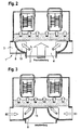
- Fig. 3
- eine geschnittene Ansicht der Lüftungsvorrichtung von Fig. 1, bei der die Luftklappen in der Umluftstellung sind,
- Fig. 4
- eine geschnittene Ansicht einer ersten Variante der Lüftungsvorrichtung, bei der die Luftklappen in der Frischluftstellung durchgezogen und in der Umluftstellung gestrichelt dargestellt sind, und
- Fig. 5
- eine geschnittene Ansicht einer zweiten Variante der Lüftungsvorrichtung mit Darstellung der Luftklappen entsprechend Fig. 4.
- Fig. 1
- a perspective view of a ventilation device according to the embodiment,
- Fig. 2
- a sectional view of the ventilation device of Fig. 1 with Fig. 1 corresponding flap positions (fresh air position),
- Fig. 3
- 1 is a sectional view of the ventilation device of FIG. 1, in which the louvers are in the circulating air position,
- Fig. 4
- a sectional view of a first variant of the ventilation device, wherein the louvers in the fresh air position drawn through and dashed lines in the air circulation position, and
- Fig. 5
- a sectional view of a second variant of the ventilation device with representation of the louvers according to Fig. 4th
Im Folgenden wird unter Bezugnahme auf die Figuren 1 bis 3 eine erfindungsgemäße Lüftungsvorrichtung 1 für einen Lkw näher beschrieben, die zwischen der Stimwand und der Fronthaube des Fahrzeugs angeordnet ist, wo die Lüftungsvorrichtung 1 relativ einfach zugänglich ist, so dass Austauscharbeiten schnell durchführbar sind.In the following, a
Die Lüftungsvorrichtung 1 weist ein Gehäuse 2 auf, welches zwei gebläseseitige Enden von Umluftkanälen 3 und ein gebläseseitiges Ende eines kurzen Frischluftkanals 4 bildet, und einen Filter 5 und zwei Ansauggebläse 6 mitsamt deren Spiralgehäuse, Laufrädern und deren mittig zwischen denselben angeordneten elektrischen Antriebsmotor aufnimmt. Im Gehäuse 2 sind femer in einem gemeinsamen Endbereich 7 der Umluftkanäle 3 und des Frischluftkanals 4 zwei als Zylinderklappen ausgebildete Luftklappen 8 vorgesehen.The
Die Luftklappen 8 weisen eine viertels-hahlzylindrisch ausgebildete Absperrfläche 9, zwei senkrecht zur Schwenkachse an den jeweiligen Enden der Absperrfläche 9 angeordnete Seitenwände 10 und an beiden parallel zur Schwenkachse S verlaufenen Enden der Absperrfläche 9 einen in radialer Richtung nach außen überstehenden Rand 11 auf, der sich auch nach außen erstreckend über die Seitenwände 10 hinzieht (siehe Fig. 1). Der Rand 11 ist vorliegend auf der einander zugewandten Seite der beiden Luftklappen 8 verbreitert ausgebildet, so dass bei beschränkter Bauraumhöhe in Richtung der Umluftkanalhöhe und relativ großer Frischluftkanalbreite, verbunden mit einer relativ großen Filterlänge LThe
Prinzipiell sind beliebige Klappenformen möglich, beispielsweise auch solche, wie in der
Die Schwenkachsen S der Luftklappen 8 sind gemäß dem Ausführungsbeispiel parallel zueinander angeordnet, wobei jede Schwenkachse S vorliegend etwa mittig bezüglich des nachfolgend angeordneten Ansauggebläses 2 angeordnet ist. Um eine optimale Strömungsverteilung auf den nachfolgenden Filter 5 zu ermöglichen, ist bei den Luftklappen 8, welche eine Absperrfläche 9 in Form eines 90°-Abschnitts eines Hohlzylinders aufweisen, und bei einem Winkel des Umluftkanals 3 zum Frischluftkanal 4 von 90° sowie einer Klappen-Schwenkbewegung von ca. 90°, die Schwenkachse S jeweils etwa in Verlängerung der seitlichen Wand des Frischluftkanals 4 angeordnet.The pivot axes S of the
Die Luftklappen 8 verschließen in ihrer einen Endstellung je einen der Umluftkanäle 3 vollständig (vgl. Fig. 1 und Fig. 2) und dadurch im Wesentlichen den gesamten gemeinsamen Endbereich 7, der durch den Frischluftkanal 4 vom Ansauggebläse 6 angesaugten Luft durchströmt wird und durch den Filter 5 auf Grund der inneren Klappenform gleichmäßig verteilt über die gesamte Filterlänge L und Filterbreite B durch den Filter 5 strömt.The
In der anderen Endstellung, die in Fig. 3 dargestellt ist, verschließen die beiden Luftklappen 8 dank des verbreitert ausgebildeten Randes 11 gemeinsam den Frischluftkanal 4. Vorliegend sind die Randenden auf Stoß angeordnet, jedoch sind auch andere, beispielsweise überlappende Anordnungen möglich oder es kann ein Steg im Luftkanal vorgesehen sein, an dem die Ränder anliegen. An den Rändern können ferner zusätzliche Dichtelemente, wie beispielsweise Dichtlippen, für eine verbesserte Abdichtung gegenüber den Anlageflächen vorgesehen sein. Ebenfalls ist eine weichere Ausgestaltung der Ränder zumindest in den äußersten Endbereichen denkbar. Eine entsprechendende abdichtende Ausgestaltung kann natürlich über den gesamten Randbereich der Luftklappe vorgesehen sein.In the other end position, which is shown in Fig. 3, close the two
Gemäß der ersten Variante, die in Fig. 4 dargestellt ist, ist die Luftklappe 8 asymmetrisch ausgebildet, wobei die Luftklappe in einem ca. 70°-Winkel eine hohlzylindrische Absperrfläche 9 entsprechendend dem ersten Ausführungsbeispiel aufweist, die an beiden Enden einen Rand 11 aufweist, jedoch ist auf der der anderen Luftklappe 8 zugewandten Seite ein schirmartig überstehender Bereich 20 vorgesehen, der ebenfalls durch einen Rand 21 abgeschlossen ist. Sowohl für den Rand 11 als auch den Rand 21 sind am Gehäuse in den Endbereichen der Luftkanäle 3 und 4, wie aus der Darstellung von Fig. 4 ersichtlich ist, entsprechende Anlageflächen ausgebildet, um in den Klappenendstellungen ein ausreichendes Abdichten zu ermöglichen.According to the first variant, which is shown in Fig. 4, the
In der Mitte zwischen den beiden Luftklappen 8 ist zur verbesserten Abdichtung und als Endanschlag ein V-förmig ausgebildeter Steg 22 angeordnet, an welchem die Ränder 21 der Luftklappe 8 im Umluftbetrieb anliegen.In the middle between the two
In Folge der schirmartigen Ausgestaltung der Luftklappe 8 kann bei relativ geringer Umluftkanalhöhe und relativ großer Filterbreite auf relativ einfache Weise und bei einem für beide Endstellungen optimierten Strömungsverlauf eine dem zuvor beschriebenen Ausführungsbeispiel entsprechende Klappenanordnung vorgesehen werden.As a result of the umbrella-like design of the
Gemäß der in Fig. 5 dargestellten zweiten Variante sind die Luftklappen 8 nicht nur spiegelbildlich zu einer Ebene ausgebildet, die parallel zur Blattebene der Darstellung von Fig. 5 ist, sondem auch spiegelbildlich zu einer Ebene, die in radialer Richtung der Schwenkachse S quer durch die Luftklappe 8 verläuft. Somit kann auf beiden Seiten die gleiche Luftklappe 8 verwendet werden, wodurch die Anzahl unterschiedlicher Teile verringert werden kann. Um jedoch die unterschiedlichen Filterlängen L und der entsprechenden Abmessungen der Luftklappen auf Grund der Begrenzung der Bauraumhöhe seitens der Luftklappen auszugleichen, ist vorliegend ein Zwischenstück 32 am Umluftkanalende vorgesehen, welches den Zwischenraum zwischen Luftklappe und filterseitigem Ende des Umluftkanals abdeckt, so dass bei Frischluftbetrieb keine Umluft durch den Zwischenraum gelangen kann. Die Luftverteilung auf den Filter ist etwas ungleichmäßiger, insbesondere in den äußeren Endbereichen, jedoch ist eine einfachere Anpassung an unterschiedliche Filterbreiten möglich.According to the second variant shown in Fig. 5, the
Claims (12)
Applications Claiming Priority (1)
| Application Number | Priority Date | Filing Date | Title |
|---|---|---|---|
| DE200510019912 DE102005019912A1 (en) | 2005-04-27 | 2005-04-27 | Ventilation device, in particular for a motor vehicle |
Publications (3)
| Publication Number | Publication Date |
|---|---|
| EP1717070A2 true EP1717070A2 (en) | 2006-11-02 |
| EP1717070A3 EP1717070A3 (en) | 2008-02-20 |
| EP1717070B1 EP1717070B1 (en) | 2010-06-16 |
Family
ID=36694380
Family Applications (1)
| Application Number | Title | Priority Date | Filing Date |
|---|---|---|---|
| EP20060007106 Expired - Fee Related EP1717070B1 (en) | 2005-04-27 | 2006-04-04 | Ventilation device, in particular for a motor vehicle |
Country Status (2)
| Country | Link |
|---|---|
| EP (1) | EP1717070B1 (en) |
| DE (2) | DE102005019912A1 (en) |
Cited By (1)
| Publication number | Priority date | Publication date | Assignee | Title |
|---|---|---|---|---|
| US7625273B2 (en) * | 2003-05-07 | 2009-12-01 | Behr Gmbh & Co. Kg | Air channel flap and flow guiding device |
Families Citing this family (1)
| Publication number | Priority date | Publication date | Assignee | Title |
|---|---|---|---|---|
| DE102007026808A1 (en) * | 2007-06-06 | 2008-12-11 | Behr Gmbh & Co. Kg | Blower arrangement for ventilation of a vehicle |
Citations (3)
| Publication number | Priority date | Publication date | Assignee | Title |
|---|---|---|---|---|
| DE9216412U1 (en) | 1991-12-13 | 1993-01-21 | Siemens Ag, 8000 Muenchen, De | |
| EP0578582B1 (en) | 1992-07-09 | 1996-03-13 | Valeo Climatisation | Device for heating, ventilating and/or air conditioning the interior of a motor vehicle |
| DE10053814A1 (en) | 1999-12-07 | 2001-06-13 | Behr Gmbh & Co | Air flap for ventilation, heating or conditioning unit of motor vehicle has first outer edge including with hinge axis a first face, and second outer edge including with hinge axis a second face, the first face being larger than second |
Family Cites Families (5)
| Publication number | Priority date | Publication date | Assignee | Title |
|---|---|---|---|---|
| FR2762888B1 (en) * | 1997-04-30 | 1999-07-30 | Valeo Climatisation | MULTIPLE SHUTTER AIR DISTRIBUTION DEVICE FOR MOTOR VEHICLE |
| JPH11235913A (en) * | 1998-02-20 | 1999-08-31 | Calsonic Corp | Intake unit of air conditioner for automobile |
| JP2001105834A (en) * | 1999-10-13 | 2001-04-17 | Zexel Valeo Climate Control Corp | Intake device |
| JP2002012016A (en) * | 2000-06-29 | 2002-01-15 | Denso Corp | Inside/outside air switching device |
| JP3979214B2 (en) * | 2002-07-29 | 2007-09-19 | 株式会社デンソー | Blower unit mounting structure |
-
2005
- 2005-04-27 DE DE200510019912 patent/DE102005019912A1/en not_active Withdrawn
-
2006
- 2006-04-04 DE DE200650007210 patent/DE502006007210D1/en active Active
- 2006-04-04 EP EP20060007106 patent/EP1717070B1/en not_active Expired - Fee Related
Patent Citations (3)
| Publication number | Priority date | Publication date | Assignee | Title |
|---|---|---|---|---|
| DE9216412U1 (en) | 1991-12-13 | 1993-01-21 | Siemens Ag, 8000 Muenchen, De | |
| EP0578582B1 (en) | 1992-07-09 | 1996-03-13 | Valeo Climatisation | Device for heating, ventilating and/or air conditioning the interior of a motor vehicle |
| DE10053814A1 (en) | 1999-12-07 | 2001-06-13 | Behr Gmbh & Co | Air flap for ventilation, heating or conditioning unit of motor vehicle has first outer edge including with hinge axis a first face, and second outer edge including with hinge axis a second face, the first face being larger than second |
Cited By (1)
| Publication number | Priority date | Publication date | Assignee | Title |
|---|---|---|---|---|
| US7625273B2 (en) * | 2003-05-07 | 2009-12-01 | Behr Gmbh & Co. Kg | Air channel flap and flow guiding device |
Also Published As
| Publication number | Publication date |
|---|---|
| EP1717070A3 (en) | 2008-02-20 |
| DE502006007210D1 (en) | 2010-07-29 |
| DE102005019912A1 (en) | 2006-11-02 |
| EP1717070B1 (en) | 2010-06-16 |
Similar Documents
| Publication | Publication Date | Title |
|---|---|---|
| DE102011051489B4 (en) | Blower Luftansaugungsvorrichtung | |
| DE69831387T2 (en) | AIR CONDITIONING | |
| CH669431A5 (en) | ||
| DE19963796A1 (en) | Combined heater, ventilator, air conditioner esp. for motor vehicles has integral divider channel to divide intake air into central and peripheral flows | |
| DE102017115012B3 (en) | Ventilation duct for a ventilation device of a motor vehicle | |
| DE102005024444A1 (en) | Cooling system for motor vehicle engine, has air-conduction unit and heat exchanger arranged so parallel projection of conduction air penetration surface in longitudinal direction of vehicle protrudes partly beyond heat exchanger | |
| WO2014170398A1 (en) | Motor vehicle engine cooling fan shroud having dynamic pressure flaps | |
| DE102008021015A1 (en) | Arrangement for mixing gaseous media, e.g. air in vehicle air conditioning system, and blocking cross-section has first, second elements that interact to define different open cross-sections in channel; each is rotatable about fixed axis | |
| DE102015211039A1 (en) | Air flow control device and ventilation, heating or air conditioning | |
| EP1717070B1 (en) | Ventilation device, in particular for a motor vehicle | |
| DE102018211809A1 (en) | Housing for a fan and fan | |
| DE10053814B4 (en) | Air damper for a ventilation, heating or air conditioning system of a motor vehicle | |
| DE10147112A1 (en) | Regulator flap e.g. for air conditioning and ventilation appliance for motor vehicles has two wings each with flat sides and associated guide element to define flow gap | |
| DE10256619B3 (en) | Air conditioner for vehicles | |
| DE102008051362A1 (en) | Radial blower housing | |
| DE10147114B4 (en) | Apparatus and method for tempering and ventilating motor vehicles | |
| DE102004015829B4 (en) | intake | |
| DE102004010632A1 (en) | Motor vehicle with two radiators for cooling of internal combustion engine by flow of fresh air and by forced ventilation means has second flow path free of forced ventilation means extending through second radiator | |
| EP0841202A2 (en) | Heating or air conditioning installation | |
| DE102005038460B3 (en) | Device for tempering and venting of motor vehicle, has separate through-flowable hot air channel, which is placed outside base housing and is formed as U-shaped hollow body with two external U-shanks and one base U-shank | |
| EP2080910B1 (en) | Fan especially for vehicle ventilation | |
| DE19631024B4 (en) | Heating or air conditioning | |
| EP1247667B1 (en) | Air flow damper | |
| DE3905092C2 (en) | ||
| DE10147111B4 (en) | Air supply device for a radial fan |
Legal Events
| Date | Code | Title | Description |
|---|---|---|---|
| PUAI | Public reference made under article 153(3) epc to a published international application that has entered the european phase |
Free format text: ORIGINAL CODE: 0009012 |
|
| AK | Designated contracting states |
Kind code of ref document: A2 Designated state(s): AT BE BG CH CY CZ DE DK EE ES FI FR GB GR HU IE IS IT LI LT LU LV MC NL PL PT RO SE SI SK TR |
|
| AX | Request for extension of the european patent |
Extension state: AL BA HR MK YU |
|
| PUAL | Search report despatched |
Free format text: ORIGINAL CODE: 0009013 |
|
| AK | Designated contracting states |
Kind code of ref document: A3 Designated state(s): AT BE BG CH CY CZ DE DK EE ES FI FR GB GR HU IE IS IT LI LT LU LV MC NL PL PT RO SE SI SK TR |
|
| AX | Request for extension of the european patent |
Extension state: AL BA HR MK YU |
|
| 17P | Request for examination filed |
Effective date: 20080820 |
|
| 17Q | First examination report despatched |
Effective date: 20080925 |
|
| AKX | Designation fees paid |
Designated state(s): DE FR |
|
| GRAP | Despatch of communication of intention to grant a patent |
Free format text: ORIGINAL CODE: EPIDOSNIGR1 |
|
| GRAS | Grant fee paid |
Free format text: ORIGINAL CODE: EPIDOSNIGR3 |
|
| GRAA | (expected) grant |
Free format text: ORIGINAL CODE: 0009210 |
|
| AK | Designated contracting states |
Kind code of ref document: B1 Designated state(s): DE FR |
|
| REF | Corresponds to: |
Ref document number: 502006007210 Country of ref document: DE Date of ref document: 20100729 Kind code of ref document: P |
|
| PLBE | No opposition filed within time limit |
Free format text: ORIGINAL CODE: 0009261 |
|
| STAA | Information on the status of an ep patent application or granted ep patent |
Free format text: STATUS: NO OPPOSITION FILED WITHIN TIME LIMIT |
|
| 26N | No opposition filed |
Effective date: 20110317 |
|
| REG | Reference to a national code |
Ref country code: DE Ref legal event code: R097 Ref document number: 502006007210 Country of ref document: DE Effective date: 20110316 |
|
| REG | Reference to a national code |
Ref country code: DE Ref legal event code: R082 Ref document number: 502006007210 Country of ref document: DE Representative=s name: GRAUEL, ANDREAS, DIPL.-PHYS. DR. RER. NAT., DE |
|
| REG | Reference to a national code |
Ref country code: DE Ref legal event code: R081 Ref document number: 502006007210 Country of ref document: DE Owner name: MAHLE INTERNATIONAL GMBH, DE Free format text: FORMER OWNER: BEHR GMBH & CO. KG, 70469 STUTTGART, DE Effective date: 20150227 Ref country code: DE Ref legal event code: R082 Ref document number: 502006007210 Country of ref document: DE Representative=s name: GRAUEL, ANDREAS, DIPL.-PHYS. DR. RER. NAT., DE Effective date: 20150227 |
|
| REG | Reference to a national code |
Ref country code: FR Ref legal event code: PLFP Year of fee payment: 11 |
|
| REG | Reference to a national code |
Ref country code: FR Ref legal event code: PLFP Year of fee payment: 12 |
|
| REG | Reference to a national code |
Ref country code: FR Ref legal event code: PLFP Year of fee payment: 13 |
|
| PGFP | Annual fee paid to national office [announced via postgrant information from national office to epo] |
Ref country code: DE Payment date: 20190619 Year of fee payment: 14 |
|
| PGFP | Annual fee paid to national office [announced via postgrant information from national office to epo] |
Ref country code: FR Payment date: 20190423 Year of fee payment: 14 |
|
| REG | Reference to a national code |
Ref country code: DE Ref legal event code: R119 Ref document number: 502006007210 Country of ref document: DE |
|
| PG25 | Lapsed in a contracting state [announced via postgrant information from national office to epo] |
Ref country code: DE Free format text: LAPSE BECAUSE OF NON-PAYMENT OF DUE FEES Effective date: 20201103 Ref country code: FR Free format text: LAPSE BECAUSE OF NON-PAYMENT OF DUE FEES Effective date: 20200430 |