EP1717006A1 - Apparatus for manufacturing multicolour plastic skins. - Google Patents
Apparatus for manufacturing multicolour plastic skins. Download PDFInfo
- Publication number
- EP1717006A1 EP1717006A1 EP06110368A EP06110368A EP1717006A1 EP 1717006 A1 EP1717006 A1 EP 1717006A1 EP 06110368 A EP06110368 A EP 06110368A EP 06110368 A EP06110368 A EP 06110368A EP 1717006 A1 EP1717006 A1 EP 1717006A1
- Authority
- EP
- European Patent Office
- Prior art keywords
- webs
- plastic
- cover
- seals
- areas
- Prior art date
- Legal status (The legal status is an assumption and is not a legal conclusion. Google has not performed a legal analysis and makes no representation as to the accuracy of the status listed.)
- Granted
Links
Images
Classifications
-
- B—PERFORMING OPERATIONS; TRANSPORTING
- B29—WORKING OF PLASTICS; WORKING OF SUBSTANCES IN A PLASTIC STATE IN GENERAL
- B29C—SHAPING OR JOINING OF PLASTICS; SHAPING OF MATERIAL IN A PLASTIC STATE, NOT OTHERWISE PROVIDED FOR; AFTER-TREATMENT OF THE SHAPED PRODUCTS, e.g. REPAIRING
- B29C41/00—Shaping by coating a mould, core or other substrate, i.e. by depositing material and stripping-off the shaped article; Apparatus therefor
- B29C41/02—Shaping by coating a mould, core or other substrate, i.e. by depositing material and stripping-off the shaped article; Apparatus therefor for making articles of definite length, i.e. discrete articles
- B29C41/18—Slush casting, i.e. pouring moulding material into a hollow mould with excess material being poured off
-
- B—PERFORMING OPERATIONS; TRANSPORTING
- B29—WORKING OF PLASTICS; WORKING OF SUBSTANCES IN A PLASTIC STATE IN GENERAL
- B29C—SHAPING OR JOINING OF PLASTICS; SHAPING OF MATERIAL IN A PLASTIC STATE, NOT OTHERWISE PROVIDED FOR; AFTER-TREATMENT OF THE SHAPED PRODUCTS, e.g. REPAIRING
- B29C41/00—Shaping by coating a mould, core or other substrate, i.e. by depositing material and stripping-off the shaped article; Apparatus therefor
- B29C41/02—Shaping by coating a mould, core or other substrate, i.e. by depositing material and stripping-off the shaped article; Apparatus therefor for making articles of definite length, i.e. discrete articles
- B29C41/22—Making multilayered or multicoloured articles
-
- B—PERFORMING OPERATIONS; TRANSPORTING
- B29—WORKING OF PLASTICS; WORKING OF SUBSTANCES IN A PLASTIC STATE IN GENERAL
- B29C—SHAPING OR JOINING OF PLASTICS; SHAPING OF MATERIAL IN A PLASTIC STATE, NOT OTHERWISE PROVIDED FOR; AFTER-TREATMENT OF THE SHAPED PRODUCTS, e.g. REPAIRING
- B29C41/00—Shaping by coating a mould, core or other substrate, i.e. by depositing material and stripping-off the shaped article; Apparatus therefor
- B29C41/34—Component parts, details or accessories; Auxiliary operations
-
- B—PERFORMING OPERATIONS; TRANSPORTING
- B29—WORKING OF PLASTICS; WORKING OF SUBSTANCES IN A PLASTIC STATE IN GENERAL
- B29C—SHAPING OR JOINING OF PLASTICS; SHAPING OF MATERIAL IN A PLASTIC STATE, NOT OTHERWISE PROVIDED FOR; AFTER-TREATMENT OF THE SHAPED PRODUCTS, e.g. REPAIRING
- B29C33/00—Moulds or cores; Details thereof or accessories therefor
- B29C33/0038—Moulds or cores; Details thereof or accessories therefor with sealing means or the like
Definitions
- the invention relates to a device for producing multicolored plastic molded skins, in particular for motor vehicle parts, such as e.g. Dashboards and door panels, wherein the plastic molded skins are constructed in the sintering process by a successive multiple continuous melting of plastic powder of different color on a surface of a heated mold, wherein provided with plastic powder of different color / sintered areas of the surface of the mold by projections or webs on the surface are separated from each other.
- the EP 0 972 625 A1 describes for this purpose a device, namely a tool mold for the production of two-color plastic molded skins for motor vehicle parts, ie essentially dashboards, door trim, etc.
- the method of production used here for producing sintered films / slush skins is rotational sintering, in which a plastic powder is located in the rotating mold and melts at appropriately heated wall parts of the mold.
- the device shown here has two different lower parts of the mold boxes.
- the lower parts of the mold boxes which also each include the powder bed, are detachably arranged with respect to the single upper mold box to which the plastic powder melts.
- the first lower molding box now has a cupped and protruding into the interior projection with which - as with a mask - parts of the upper mold box are covered.
- a powder of a first color is melted by rotational sintering, whereby the lying under the cup-shaped cover areas of the upper mold box are not hit and thus remain free of powder.
- the first lower mold box is replaced by a second lower mold box containing a powder of a different color and having no covers.
- sintering melts at the previously reserved area of the upper mold box and on the back of the existing molded skin powder with the new color. After cooling and removal of the molded skin from the tool to get on the tool facing and future outside a two-tone plastic molded skin.
- the cup-shaped cover of the lower molding box projecting into the interior space must be carefully sealed against the upper molding box so that no sintering powder of the first color penetrates into the covering area.
- the cup-shaped projection on its edges on sealing elements which are elastic and / or hollow inside and can optionally be applied internally with pressure or elastic media.
- the disadvantage here is the high workload to change the lower box shapes and the difficult seal the mask, ie the seal between the edges of the cup-shaped and projecting into the interior cover of the lower mold box and the inside of the upper mold box.
- thermal expansions and different and caused by complicated inner shapes of the upper mold box pressure ratios of the seals lead to leaks and irregular investment, which can blur the color boundaries.
- the invention therefore an object of the invention to provide an apparatus for producing two-color plastic molded skins by means of powder internals, with which a cover or mask is easy to apply and remove, which ensures an exact color separation without blurring of the individual color areas, and for Various methods of sintering technology can be adapted.
- At least one of the regions of the surface delimited by the webs is provided with a cover or mask during the melting of plastic powder of one color, which rests with its edge regions on the webs, the edge regions of the cover extending the webs in the direction of the uncovered regions of the surface surmount with a supernatant.
- An advantageous embodiment is that the supernatant in all directions between 1 and 5 mm, preferably 2 mm. This is a supernatant that provides the best results so far with the usual sieve distributions / grain sizes of the sintered powders.
- a further advantageous embodiment is that the edge regions of the cover have seals which rest on the webs. This will be a safe Covering the limited or enclosed by the webs areas reached.
- seals are made of permanently elastic and temperature-resistant material, preferably of polyurethane or silicone rubber. This achieves a clean edge formation between the individual color or sintering areas over a long period of use and thermal cycling.
- a further advantageous embodiment is that the dimensions of the covers or masks compensate for thermal expansion of the mold provided with webs. In the required for the sintering process temperatures of 180 to 250 ° C, the subsequent heat transfer subsequent strains of the edge regions of the covers make strongly noticeable and lead to leaks, if not such a compensation measure is provided immediately in the construction of the covers.
- a further advantageous embodiment is that in the covered and limited by web areas of the surface means for generating an overpressure are present, preferably connections to pressure lines. This reliably avoids the penetration of powder particles into the covered areas.
- the structure of powder beds and thus a thickening of the powder layer in the edge region of the cover can be reduced, for example, by compressed air exiting via the sealing gap.
- a further advantageous embodiment is that the seals are hollow and can be acted upon with internal pressure. Such a measure may be useful alone or as a support for internal pressurization of the covered areas to enhance or control the sealing effect.
- a further advantageous embodiment is that the seals have pressure outlet openings in the direction of the webs. This will both a Leakage of sealing medium over the sealing gap achieved, whereby the structure of powder beds is reduced, as well as the generation of an overpressure in the covered and limited by webs area of the surface.
- a particularly advantageous use of the device results in the production of plastic molded skins by spray sintering.
- this is due to the "overspray" which occurs in the spray nozzles used, i. the forming spray cone, a particularly pronounced powder bed and Vedickung the powder layer at the edge regions of the cover, which can now be reduced by the inventive device in its harmful effects.
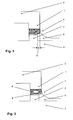
- FIG. 1 shows an edge region 1 of a cover or mask 3 of a device according to the invention resting on a separating web 2.
- the dividing web 2 is located in the surface of a molding tool 4.
- the edge region 1 of the cover 3 projects beyond the dividing webs 2 in the direction of the uncovered regions of the surface with a projection 5.
- Figure 2 shows the same device with a cross-section through a hollow formed and pressurized with internal pressure seal 8, whereby the sealing effect can be enhanced or controlled.
- the seal has pressure outlet openings 9 in the direction of the web 2. In this way, both a leakage of sealing medium is achieved via the sealing gap, whereby the structure of powder beds is also reduced, as well as the generation of an overpressure in the covered and limited by webs area of the surface
Landscapes
- Engineering & Computer Science (AREA)
- Mechanical Engineering (AREA)
- Moulding By Coating Moulds (AREA)
Abstract
Description
Die Erfindung betrifft eine Vorrichtung zur Herstellung von mehrfarbigen Kunststoff-Formhäuten, insbesondere für Kraftfahrzeugteile wie z.B. Armaturenbretter und Türverkleidungen, wobei die Kunststoff-Formhäute im Sinterverfahren durch ein nacheinander erfolgendes mehrfaches kontinuierliches Anschmelzen von Kunststoffpulver verschiedener Farbe an einer Oberfläche eines erwärmten Formwerkzeuges aufgebaut werden, wobei die mit Kunststoffpulver unterschiedlicher Farbe versehenen / gesinterten Bereiche der Oberfläche des Formwerkzeugs durch Vorsprünge oder Stege auf der Oberfläche voneinander getrennt sind.The invention relates to a device for producing multicolored plastic molded skins, in particular for motor vehicle parts, such as e.g. Dashboards and door panels, wherein the plastic molded skins are constructed in the sintering process by a successive multiple continuous melting of plastic powder of different color on a surface of a heated mold, wherein provided with plastic powder of different color / sintered areas of the surface of the mold by projections or webs on the surface are separated from each other.
Verfahren zur Herstellung zweifarbiger Slushhäute mit der "Maskentechnik" sind bekannt. Die
Die hier gezeigte Einrichtung weist zwei verschiedene untere Teile der Werkzeugformkästen auf. Die unteren Teile der Werkzeugformkästen, welche jeweils auch das Pulverbett beinhalten, sind lösbar angeordnet in Bezug auf den einzigen oberen Werkzeugformkasten, an welchen das Kunststoffpulver anschmilzt. Für die Herstellung von zweifarbigen Kunststoff-Formhäuten weist nun der erste untere Formkasten einen schalenförmige und in den Innenraum ragenden Vorsprung auf, mit dem - wie mit einer Maske - Teile des oberen Formkastens abgedeckt werden.The device shown here has two different lower parts of the mold boxes. The lower parts of the mold boxes, which also each include the powder bed, are detachably arranged with respect to the single upper mold box to which the plastic powder melts. For the production of two-tone plastic molded skins, the first lower molding box now has a cupped and protruding into the interior projection with which - as with a mask - parts of the upper mold box are covered.
In einem ersten Arbeitsgang wird durch Rotationssintern ein Pulver einer ersten Farbe angeschmolzen, wobei die unter der schalenförmigen Abdeckung liegenden Bereiche des oberen Formkastens nicht getroffen werden und somit frei von Pulver bleiben.In a first operation, a powder of a first color is melted by rotational sintering, whereby the lying under the cup-shaped cover areas of the upper mold box are not hit and thus remain free of powder.
Vor einem zweiten Arbeitsgang wird der erste untere Formkasten durch einen zweiten unteren Formkasten ersetzt, der ein Pulver einer anderen Farbe beinhaltet und keine Abdeckungen aufweist. Beim nachfolgend wiederholten Rotationssintern schmilzt an dem vorher freigehaltene Bereich des oberen Formkastens und auf der Rückseite der schon bestehenden Formhaut das Pulver mit der neuen Farbe an. Nach Abkühlung und Entnahme der Formhaut aus dem Werkzeug erhält man auf der dem Werkzeug zugewandten und zukunftigen Außenseite eine zweifarbige Kunststoff-Formhaut.Before a second operation, the first lower mold box is replaced by a second lower mold box containing a powder of a different color and having no covers. In the subsequent repeated rotation sintering melts at the previously reserved area of the upper mold box and on the back of the existing molded skin powder with the new color. After cooling and removal of the molded skin from the tool to get on the tool facing and future outside a two-tone plastic molded skin.
Während des ersten Arbeitsschrittes muß die hierzu die schalenförmige und in den Innenraum ragende Abdeckung des unteren Formkasten sorgsam gegenüber dem oberen Formkasten abgedichtet werden, damit kein Sinterpulver der ersten Farbe in den Abdeckbereich gelangt. Hierzu weist der schalenförmige Vorsprung an seine Rändern Dichtungselemente auf, die elastisch und oder/innen hohl ausgebildet sind und ggf. innen mit Druck oder elastischen Medien beaufschlagt werden können.During the first working step, the cup-shaped cover of the lower molding box projecting into the interior space must be carefully sealed against the upper molding box so that no sintering powder of the first color penetrates into the covering area. For this purpose, the cup-shaped projection on its edges on sealing elements which are elastic and / or hollow inside and can optionally be applied internally with pressure or elastic media.
Von Nachteil ist hierbei der hohe Arbeitsaufwand zum Wechsel der unteren Kastenformen sowie die schwierige Dichtung der Maske, d.h. der Dichtung zwischen den Rändern der schalenförmigen und in den Innenraum ragenden Abdeckung des unteren Formkasten und der Innenseite des oberen Formkastens. Hierbei führen Wärmedehnungen und unterschiedliche und durch komplizierte Innenformen des oberen Formkastens bedingte Druckverhältnisse der Dichtungen zu Undichtigkeiten und unregelmäßiger Anlage, wodurch die Farbgrenzen verwischen können.The disadvantage here is the high workload to change the lower box shapes and the difficult seal the mask, ie the seal between the edges of the cup-shaped and projecting into the interior cover of the lower mold box and the inside of the upper mold box. In this case, thermal expansions and different and caused by complicated inner shapes of the upper mold box pressure ratios of the seals lead to leaks and irregular investment, which can blur the color boundaries.
Der Erfindung lag also die Aufgabe zugrunde, eine Vorrichtung zur Herstellung von zweifarbigen Kunststoff-Formhäuten mittels Pulversintern bereitzustellen, mit welcher eine Abdeckung oder Maske leicht aufzubringen und zu entfernen ist, die eine exakte Farbtrennung ohne Verwischen der einzelnen Farb-Bereiche sicherstellt, und die für verschiedene Verfahren der Sintertechnik angepaßt werden kann.The invention therefore an object of the invention to provide an apparatus for producing two-color plastic molded skins by means of powder internals, with which a cover or mask is easy to apply and remove, which ensures an exact color separation without blurring of the individual color areas, and for Various methods of sintering technology can be adapted.
Gelöst wir diese Aufgabe durch die Merkmale des Hauptanspruchs. Vorteilhafte Weiterbildungen sind in den Unteransprüchen erfasst.We solve this problem by the features of the main claim. Advantageous developments are included in the subclaims.
Hierbei wird mindestens einer der durch die Stege begrenzten Bereiche der Oberfläche während eines Anschmelzen von Kunststoffpulver einer Farbe mit einer Abdeckung oder Maske versehen, die mit ihren Randbereichen auf den Stegen aufliegt, wobei die Randbereiche der Abdeckung die Stege in Richtung der nicht abgedeckten Bereiche der Oberfläche mit einem Überstand überragen.In this case, at least one of the regions of the surface delimited by the webs is provided with a cover or mask during the melting of plastic powder of one color, which rests with its edge regions on the webs, the edge regions of the cover extending the webs in the direction of the uncovered regions of the surface surmount with a supernatant.
Hierdurch erreicht man eine exakte Farbtrennung ohne Verwischen der einzelnen Farb-Bereiche und vermeidet das bei den Sinterverfahren, die ja mit dem Aufbringen von Pulver arbeiten, übliche Einbrechen und Verlaufen von Pulveranhäufungen. Bei den bisher bekannten Verfahren baut sich nämlich an den Rändern von Abdeckschalen eine Häufung der Pulverschüttung und somit eine Vedickung der Pulverschicht auf, die nach Abheben der Abdeckung in Richtung auf die abgedeckten Bereiche einbricht und den Farbverlauf verwischt.This achieves an exact color separation without blurring of the individual color areas and avoids the usual breaking in and running of powder accumulations in the sintering process, which indeed work with the application of powder. In the hitherto known methods, namely, an accumulation of the powder bed and thus a thickening of the powder layer builds up on the edges of cover shells, which, after lifting off the cover, breaks in the direction of the covered areas and blurs the color gradient.
Eine vorteilhafte Ausbildung besteht darin, dass der Überstand in allen Richtungen zwischen 1 und 5 mm, vorzugsweise 2 mm beträgt. Dies ist ein Überstand, der mit den üblichen Siebverteilungen / Körnergrößen der Sinterpulver die bisher besten Ergebnisse liefert.An advantageous embodiment is that the supernatant in all directions between 1 and 5 mm, preferably 2 mm. This is a supernatant that provides the best results so far with the usual sieve distributions / grain sizes of the sintered powders.
Eine weitere vorteilhafte Ausbildung besteht darin, dass die Randbereiche der Abdeckung Dichtungen aufweisen, die auf den Stegen aufliegen. Hierdurch wird eine sichere Abdeckung der von den Stegen begrenzten bzw. eingeschlossenen Bereiche erreicht.A further advantageous embodiment is that the edge regions of the cover have seals which rest on the webs. This will be a safe Covering the limited or enclosed by the webs areas reached.
Eine weitere vorteilhafte Ausbildung besteht darin, dass die Dichtungen aus dauerelastischem und temperaturfestem Material hergestellt sind, vorzugsweise aus Polyurethan oder Silikonkautschuk. Hierdurch erreicht man auch über eine lange Anwendungszeit und thermische Wechselbelastungen eine saubere Kantenbildung zwischen den einzelnen Farb- bzw. Sinterbereichen.A further advantageous embodiment is that the seals are made of permanently elastic and temperature-resistant material, preferably of polyurethane or silicone rubber. This achieves a clean edge formation between the individual color or sintering areas over a long period of use and thermal cycling.
Eine weitere vorteilhafte Ausbildung besteht darin, dass die Abmessungen der Abdeckungen oder Masken eine Wärmedehnung des mit Stegen versehenen Formwerkzeuges kompensieren. Bei den für den Sinterprozeß erforderlichen Temperaturen von 180 bis 250° C machen sich die durch Wärmeübergang nachfolgenden Dehnungen der Randbereiche der Abdeckungen stark bemerkbar und führen zu Undichtigkeiten, wenn nicht eine solche Kompensationsmaßnahme gleich bei der Konstruktion der Abdeckungen vorgesehen wird.A further advantageous embodiment is that the dimensions of the covers or masks compensate for thermal expansion of the mold provided with webs. In the required for the sintering process temperatures of 180 to 250 ° C, the subsequent heat transfer subsequent strains of the edge regions of the covers make strongly noticeable and lead to leaks, if not such a compensation measure is provided immediately in the construction of the covers.
Eine weitere vorteilhafte Ausbildung besteht darin, dass in den abgedeckten und durch Stege begrenzten Bereiche der Oberfläche Einrichtungen zur Erzegung eines Überdrucks vorhanden sind, vorzugsweise Anschlüsse an Druckleitungen. Hierdurch vermeidet man sicher das Eindringen von Pulverpartikeln in die abgedeckten Bereiche. Zusätzlich läßt sich beispielsweise durch über den Dichtungsspalt austretende Druckluft der Aufbau von Pulverschüttungen und somit eine Vedickungen der Pulverschicht im Randbereich der Abdeckung verringern.A further advantageous embodiment is that in the covered and limited by web areas of the surface means for generating an overpressure are present, preferably connections to pressure lines. This reliably avoids the penetration of powder particles into the covered areas. In addition, the structure of powder beds and thus a thickening of the powder layer in the edge region of the cover can be reduced, for example, by compressed air exiting via the sealing gap.
Eine weitere vorteilhafte Ausbildung besteht darin, dass die Dichtungen hohl ausgebildet und mit Innendruck beaufschlagbar sind. Ein solche Maßnahme kann allein oder als Unterstützung zur Innendruckbeaufschlagung der abgedeckten Bereiche sinnvoll sein, um die Dichtwirkung zu verstärken oder zu steuern.A further advantageous embodiment is that the seals are hollow and can be acted upon with internal pressure. Such a measure may be useful alone or as a support for internal pressurization of the covered areas to enhance or control the sealing effect.
Eine weitere vorteilhafte Ausbildung besteht darin, dass die Dichtungen Druckaustrittsöffnungen in Richtung der Stege aufweisen. Hierdurch wird sowohl ein Austreten von Dichtmedium über den Dichtungsspalt erreicht, wodurch der Aufbau von Pulverschüttungen verringert wird, als auch die Erzeugung eines Überdrucks im den abgedeckten und durch Stege begrenzten Bereich der Oberfläche.A further advantageous embodiment is that the seals have pressure outlet openings in the direction of the webs. This will both a Leakage of sealing medium over the sealing gap achieved, whereby the structure of powder beds is reduced, as well as the generation of an overpressure in the covered and limited by webs area of the surface.
Eine besonders vorteilhafte Verwendung der Vorrichtung ergibt sich bei der Herstellung von Kunststoff-Formhäuten durch Sprühsintern. Bei Sprühverfahren ergibt sich nämlich durch den bei den verwendeten Sprühdüsen entstehenden "Overspray", d.h. den sich bildenden Sprühnebel-Kegel, eine besonders ausgeprägte Pulverschüttung und Vedickung der Pulverschicht an den Randbereichen der Abdeckung, die nun durch die erfindungsgemäße Vorrichtung in ihren schädlichen Wirkungen reduziert werden kann.A particularly advantageous use of the device results in the production of plastic molded skins by spray sintering. In the case of spraying processes, this is due to the "overspray" which occurs in the spray nozzles used, i. the forming spray cone, a particularly pronounced powder bed and Vedickung the powder layer at the edge regions of the cover, which can now be reduced by the inventive device in its harmful effects.
Eine ebenso vorteilhafte Verwendung der Vorrichtung ergit sich für die für die Herstellung von Kunststoff-Formhäuten durch Rotationssintern, da es durch in den Randbereiche von Stegen oder Abdeckung entstehende Stau-Wärme ebenfalls zu erhöhter ausgeprägte Pulveransammlung und Vedickung der Pulverschicht kommen kann.An equally advantageous use of the device ergit for those for the production of plastic molded skins by rotational sintering, as it may also come through increased in the edge regions of webs or cover congestion heat to increased powder accumulation and thickening of the powder layer.
Anhand eines Ausführungsbeispieles soll die Erfindung näher erläutert werden. Es zeigen
- Fig. 1
- einen Randbereich einer auf einem Trennsteg aufliegenden Abdeckung der erfindungsgemäßen Vorrichtung
- Fig. 2
- einen Querschnitt durch eine Dichtung des Randbereiches
- Fig. 1
- an edge region of a resting on a divider cover of the device according to the invention
- Fig. 2
- a cross section through a seal of the edge region
Die Figur 1 zeigt einen Randbereich 1 einer auf einem Trennsteg 2 aufliegenden Abdeckung oder Maske 3 einer erfindungsgemäßen Vorrichtung. Der Trennsteg 2 befindet sich dabei in der Oberfläche eines Formwerkzeuges 4. Der Randbereich 1 der Abdeckung 3 überragt den Trennstege 2 in Richtung der nicht abgedeckten Bereiche der Oberfläche mit einem Überstand 5.FIG. 1 shows an
Beim Sinterverfahren, d.h. beim Aufschmelzen eine Pulverschicht 6 baut sich an den Rändern der Abdeckung 3 ein Häufung der Pulverschüttung und somit eine Vedickung 7 der Pulverschicht 6 auf, die nach Abheben der Abdeckung in Richtung auf die nicht abgedeckten Bereiche einbricht. Bei der hier gezeigten Vorrichtung kann dies aber nicht zu einem Verwischen des Farbverlaufes führen, da die Verdikung lediglich in den vorher "freigehaltenen" Bereich des Überstandes 5 kippen kann.In the sintering process, ie when melting a
Figur 2 zeigt dieselbe Vorrichtung mit einem Querschnitt durch eine hohl ausgebildete und mit Innendruck beaufschlagte Dichtung 8, wodurch die Dichtwirkung verstärkt oder gesteuert werden kann.Figure 2 shows the same device with a cross-section through a hollow formed and pressurized with
Die Dichtung weist dabei Druckaustrittsöffnungen 9 in Richtung des Steges 2 auf. Hierdurch wird sowohl ein Austreten von Dichtmedium über den Dichtungsspalt erreicht, wodurch der Aufbau von Pulverschüttungen ebenso verringert wird, wie auch die Erzeugung eines Überdrucks im den abgedeckten und durch Stege begrenzten Bereich der OberflächeThe seal has
- 11
- Randbereichborder area
- 22
- Trennstegdivider
- 33
- Maske oder AbdeckungMask or cover
- 44
- Formwerkzeugmold
- 55
- ÜberstandGot over
- 66
- Pulverschichtpowder layer
- 77
- Verdickungthickening
- 88th
- Dichtungpoetry
- 99
- DruckaustrittsöffnungPressure outlet opening
Claims (10)
Applications Claiming Priority (1)
| Application Number | Priority Date | Filing Date | Title |
|---|---|---|---|
| DE200510020492 DE102005020492A1 (en) | 2005-04-29 | 2005-04-29 | Device for producing multicolored plastic molded skins |
Publications (2)
| Publication Number | Publication Date |
|---|---|
| EP1717006A1 true EP1717006A1 (en) | 2006-11-02 |
| EP1717006B1 EP1717006B1 (en) | 2009-07-22 |
Family
ID=36593130
Family Applications (1)
| Application Number | Title | Priority Date | Filing Date |
|---|---|---|---|
| EP20060110368 Active EP1717006B1 (en) | 2005-04-29 | 2006-02-24 | Apparatus for manufacturing multicolour plastic skins. |
Country Status (2)
| Country | Link |
|---|---|
| EP (1) | EP1717006B1 (en) |
| DE (2) | DE102005020492A1 (en) |
Cited By (2)
| Publication number | Priority date | Publication date | Assignee | Title |
|---|---|---|---|---|
| WO2007065600A1 (en) * | 2005-12-07 | 2007-06-14 | Johnson Controls Interiors Gmbh & Co. Kg | Method for the production of a piece of motor vehicle equipment comprising at least two surface zones, form tool, and piece of motor vehicle equipment |
| EP1935604A2 (en) * | 2006-12-23 | 2008-06-25 | Benecke-Kaliko AG | Method for manufacturing a synthetic skin with film-integrated circuit |
Families Citing this family (3)
| Publication number | Priority date | Publication date | Assignee | Title |
|---|---|---|---|---|
| ES2374184T3 (en) | 2008-02-21 | 2012-02-14 | Peguform Gmbh | PROCEDURE AND DEVICE FOR THE MANUFACTURE OF MOLDED PLASTIC COATINGS PRESENTING DIFFERENT PARTIAL ZONES. |
| EP2153966B1 (en) | 2008-08-12 | 2016-01-13 | SMP Deutschland GmbH | Method for producing plastic moulded skins with differently coloured areas |
| DE102008058192A1 (en) * | 2008-11-20 | 2010-05-27 | Volkswagen Ag | Interior component e.g. door lining, manufacturing method for motor vehicle, involves producing stream of gaseous medium within area of surface section of tool, where stream is opposite to flow direction of surrounding area |
Citations (6)
| Publication number | Priority date | Publication date | Assignee | Title |
|---|---|---|---|---|
| JPS59159309A (en) * | 1983-03-01 | 1984-09-08 | Inoue Mtp Co Ltd | Method for forming multi-color skin member |
| JPH02141213A (en) * | 1988-11-22 | 1990-05-30 | Inoue Mtp Co Ltd | Manufacture of different color skin material |
| EP0451558A2 (en) * | 1990-04-12 | 1991-10-16 | Davidson Textron Inc. | Adjustable gasket alignment block |
| JPH08290433A (en) * | 1995-04-24 | 1996-11-05 | Kasai Kogyo Co Ltd | Powder slush molding apparatus for molding two-color skin |
| EP0972625A1 (en) * | 1998-07-13 | 2000-01-19 | Ecia - Equipements Et Composants Pour L'industrie Automobile | Apparatus for manufacturing a plastic skin cover for a vehicle equipment part |
| US6071619A (en) * | 1994-06-01 | 2000-06-06 | Recticel | Method and spray mould assembly for manufacturing an elastomeric skin of at least two elastomeric materials and such elastomeric skin |
-
2005
- 2005-04-29 DE DE200510020492 patent/DE102005020492A1/en not_active Ceased
-
2006
- 2006-02-24 DE DE200650004278 patent/DE502006004278D1/en active Active
- 2006-02-24 EP EP20060110368 patent/EP1717006B1/en active Active
Patent Citations (6)
| Publication number | Priority date | Publication date | Assignee | Title |
|---|---|---|---|---|
| JPS59159309A (en) * | 1983-03-01 | 1984-09-08 | Inoue Mtp Co Ltd | Method for forming multi-color skin member |
| JPH02141213A (en) * | 1988-11-22 | 1990-05-30 | Inoue Mtp Co Ltd | Manufacture of different color skin material |
| EP0451558A2 (en) * | 1990-04-12 | 1991-10-16 | Davidson Textron Inc. | Adjustable gasket alignment block |
| US6071619A (en) * | 1994-06-01 | 2000-06-06 | Recticel | Method and spray mould assembly for manufacturing an elastomeric skin of at least two elastomeric materials and such elastomeric skin |
| JPH08290433A (en) * | 1995-04-24 | 1996-11-05 | Kasai Kogyo Co Ltd | Powder slush molding apparatus for molding two-color skin |
| EP0972625A1 (en) * | 1998-07-13 | 2000-01-19 | Ecia - Equipements Et Composants Pour L'industrie Automobile | Apparatus for manufacturing a plastic skin cover for a vehicle equipment part |
Non-Patent Citations (3)
| Title |
|---|
| PATENT ABSTRACTS OF JAPAN vol. 009, no. 011 (M - 351) 18 January 1985 (1985-01-18) * |
| PATENT ABSTRACTS OF JAPAN vol. 014, no. 379 (M - 1012) 16 August 1990 (1990-08-16) * |
| PATENT ABSTRACTS OF JAPAN vol. 1997, no. 03 31 March 1997 (1997-03-31) * |
Cited By (2)
| Publication number | Priority date | Publication date | Assignee | Title |
|---|---|---|---|---|
| WO2007065600A1 (en) * | 2005-12-07 | 2007-06-14 | Johnson Controls Interiors Gmbh & Co. Kg | Method for the production of a piece of motor vehicle equipment comprising at least two surface zones, form tool, and piece of motor vehicle equipment |
| EP1935604A2 (en) * | 2006-12-23 | 2008-06-25 | Benecke-Kaliko AG | Method for manufacturing a synthetic skin with film-integrated circuit |
Also Published As
| Publication number | Publication date |
|---|---|
| DE502006004278D1 (en) | 2009-09-03 |
| DE102005020492A1 (en) | 2006-11-02 |
| EP1717006B1 (en) | 2009-07-22 |
Similar Documents
| Publication | Publication Date | Title |
|---|---|---|
| EP0835399B1 (en) | Flat gasket ring and method of producing the same | |
| EP0958032B1 (en) | Filter cartridge | |
| EP1717006B1 (en) | Apparatus for manufacturing multicolour plastic skins. | |
| EP2077935B2 (en) | Method for the production of molded skins from multiple plastics | |
| EP1522472B1 (en) | Wiper blade | |
| EP1717005B1 (en) | Method of producing multicolour plastic skins | |
| WO2008040322A2 (en) | Deformable substrate with microstructured surface composed of applied material, and method for producing such a substrate | |
| EP1767327B1 (en) | Method of manufacturing an interior trim panel with a two piece skin and trim panel manufactured according to the method | |
| EP2093039A1 (en) | Method and device for manufacturing plastic skins featuring different segments | |
| DE69517213T2 (en) | Method and device for hardening a glass pane by means of contact | |
| DE19854760C2 (en) | Method for producing a removable surface protection on a painted motor vehicle body | |
| EP2743005A1 (en) | Method for step free painting a bicoloured bodywork trim, masking template and bodywork trim | |
| WO2008113615A2 (en) | Method and device for the production of molded skins made of a plurality of plastics | |
| DE69001512T2 (en) | Device for tempering glass panes by contact. | |
| DE102010007493A1 (en) | Process for the preparation of an adhesive closure part, process for the production of a molding roll and molding roll | |
| EP1606093B1 (en) | Method for the production of plastic skins by powder sintering and corresponding sintering tool | |
| EP2533959B1 (en) | Method for producing an adhesive closure part, method for the production of a shaping roller and shaping roller | |
| WO2008131855A1 (en) | Mold, device, and method for producing molded skins and molded bodies made of plastic | |
| EP0690956A1 (en) | Process for casting a light metal cover and cast light metal cover | |
| WO1999049986A1 (en) | Plastic section for sealing gaps between two motor vehicle body parts | |
| DE102006025665B4 (en) | Method for producing a molded skin with a weakened area | |
| DE4002173A1 (en) | POLYMER MOLDING DEVICE | |
| EP2129504B1 (en) | Method and device for the production of molded skins from a plurality of plastic materials having improved properties during airbag deployment at low temperatures | |
| DE2314574A1 (en) | NON-INFLATABLE VEHICLE TIRES AND DEVICE FOR THE PRODUCTION THEREOF | |
| EP0853983B1 (en) | Preserving of a car |
Legal Events
| Date | Code | Title | Description |
|---|---|---|---|
| PUAI | Public reference made under article 153(3) epc to a published international application that has entered the european phase |
Free format text: ORIGINAL CODE: 0009012 |
|
| AK | Designated contracting states |
Kind code of ref document: A1 Designated state(s): AT BE BG CH CY CZ DE DK EE ES FI FR GB GR HU IE IS IT LI LT LU LV MC NL PL PT RO SE SI SK TR |
|
| AX | Request for extension of the european patent |
Extension state: AL BA HR MK YU |
|
| 17P | Request for examination filed |
Effective date: 20070502 |
|
| 17Q | First examination report despatched |
Effective date: 20070606 |
|
| AKX | Designation fees paid |
Designated state(s): AT BE BG CH CY CZ DE DK EE ES FI FR GB GR HU IE IS IT LI LT LU LV MC NL PL PT RO SE SI SK TR |
|
| AXX | Extension fees paid |
Extension state: YU Payment date: 20070502 Extension state: HR Payment date: 20070502 Extension state: BA Payment date: 20070502 Extension state: MK Payment date: 20070502 Extension state: AL Payment date: 20070502 |
|
| GRAP | Despatch of communication of intention to grant a patent |
Free format text: ORIGINAL CODE: EPIDOSNIGR1 |
|
| GRAS | Grant fee paid |
Free format text: ORIGINAL CODE: EPIDOSNIGR3 |
|
| GRAA | (expected) grant |
Free format text: ORIGINAL CODE: 0009210 |
|
| AK | Designated contracting states |
Kind code of ref document: B1 Designated state(s): AT BE BG CH CY CZ DE DK EE ES FI FR GB GR HU IE IS IT LI LT LU LV MC NL PL PT RO SE SI SK TR |
|
| AX | Request for extension of the european patent |
Extension state: AL BA HR MK YU |
|
| REG | Reference to a national code |
Ref country code: GB Ref legal event code: FG4D Free format text: NOT ENGLISH |
|
| REG | Reference to a national code |
Ref country code: CH Ref legal event code: EP |
|
| REG | Reference to a national code |
Ref country code: IE Ref legal event code: FG4D |
|
| REF | Corresponds to: |
Ref document number: 502006004278 Country of ref document: DE Date of ref document: 20090903 Kind code of ref document: P |
|
| NLV1 | Nl: lapsed or annulled due to failure to fulfill the requirements of art. 29p and 29m of the patents act | ||
| PG25 | Lapsed in a contracting state [announced via postgrant information from national office to epo] |
Ref country code: SE Free format text: LAPSE BECAUSE OF FAILURE TO SUBMIT A TRANSLATION OF THE DESCRIPTION OR TO PAY THE FEE WITHIN THE PRESCRIBED TIME-LIMIT Effective date: 20090722 Ref country code: FI Free format text: LAPSE BECAUSE OF FAILURE TO SUBMIT A TRANSLATION OF THE DESCRIPTION OR TO PAY THE FEE WITHIN THE PRESCRIBED TIME-LIMIT Effective date: 20090722 Ref country code: ES Free format text: LAPSE BECAUSE OF FAILURE TO SUBMIT A TRANSLATION OF THE DESCRIPTION OR TO PAY THE FEE WITHIN THE PRESCRIBED TIME-LIMIT Effective date: 20091102 Ref country code: IS Free format text: LAPSE BECAUSE OF FAILURE TO SUBMIT A TRANSLATION OF THE DESCRIPTION OR TO PAY THE FEE WITHIN THE PRESCRIBED TIME-LIMIT Effective date: 20091122 Ref country code: LT Free format text: LAPSE BECAUSE OF FAILURE TO SUBMIT A TRANSLATION OF THE DESCRIPTION OR TO PAY THE FEE WITHIN THE PRESCRIBED TIME-LIMIT Effective date: 20090722 |
|
| PG25 | Lapsed in a contracting state [announced via postgrant information from national office to epo] |
Ref country code: NL Free format text: LAPSE BECAUSE OF FAILURE TO SUBMIT A TRANSLATION OF THE DESCRIPTION OR TO PAY THE FEE WITHIN THE PRESCRIBED TIME-LIMIT Effective date: 20090722 Ref country code: PL Free format text: LAPSE BECAUSE OF FAILURE TO SUBMIT A TRANSLATION OF THE DESCRIPTION OR TO PAY THE FEE WITHIN THE PRESCRIBED TIME-LIMIT Effective date: 20090722 Ref country code: SI Free format text: LAPSE BECAUSE OF FAILURE TO SUBMIT A TRANSLATION OF THE DESCRIPTION OR TO PAY THE FEE WITHIN THE PRESCRIBED TIME-LIMIT Effective date: 20090722 Ref country code: LV Free format text: LAPSE BECAUSE OF FAILURE TO SUBMIT A TRANSLATION OF THE DESCRIPTION OR TO PAY THE FEE WITHIN THE PRESCRIBED TIME-LIMIT Effective date: 20090722 |
|
| REG | Reference to a national code |
Ref country code: IE Ref legal event code: FD4D |
|
| PG25 | Lapsed in a contracting state [announced via postgrant information from national office to epo] |
Ref country code: BG Free format text: LAPSE BECAUSE OF FAILURE TO SUBMIT A TRANSLATION OF THE DESCRIPTION OR TO PAY THE FEE WITHIN THE PRESCRIBED TIME-LIMIT Effective date: 20091022 Ref country code: PT Free format text: LAPSE BECAUSE OF FAILURE TO SUBMIT A TRANSLATION OF THE DESCRIPTION OR TO PAY THE FEE WITHIN THE PRESCRIBED TIME-LIMIT Effective date: 20091122 |
|
| PG25 | Lapsed in a contracting state [announced via postgrant information from national office to epo] |
Ref country code: DK Free format text: LAPSE BECAUSE OF FAILURE TO SUBMIT A TRANSLATION OF THE DESCRIPTION OR TO PAY THE FEE WITHIN THE PRESCRIBED TIME-LIMIT Effective date: 20090722 Ref country code: IE Free format text: LAPSE BECAUSE OF FAILURE TO SUBMIT A TRANSLATION OF THE DESCRIPTION OR TO PAY THE FEE WITHIN THE PRESCRIBED TIME-LIMIT Effective date: 20090722 Ref country code: RO Free format text: LAPSE BECAUSE OF FAILURE TO SUBMIT A TRANSLATION OF THE DESCRIPTION OR TO PAY THE FEE WITHIN THE PRESCRIBED TIME-LIMIT Effective date: 20090722 Ref country code: CZ Free format text: LAPSE BECAUSE OF FAILURE TO SUBMIT A TRANSLATION OF THE DESCRIPTION OR TO PAY THE FEE WITHIN THE PRESCRIBED TIME-LIMIT Effective date: 20090722 Ref country code: EE Free format text: LAPSE BECAUSE OF FAILURE TO SUBMIT A TRANSLATION OF THE DESCRIPTION OR TO PAY THE FEE WITHIN THE PRESCRIBED TIME-LIMIT Effective date: 20090722 |
|
| PLBE | No opposition filed within time limit |
Free format text: ORIGINAL CODE: 0009261 |
|
| STAA | Information on the status of an ep patent application or granted ep patent |
Free format text: STATUS: NO OPPOSITION FILED WITHIN TIME LIMIT |
|
| PG25 | Lapsed in a contracting state [announced via postgrant information from national office to epo] |
Ref country code: SK Free format text: LAPSE BECAUSE OF FAILURE TO SUBMIT A TRANSLATION OF THE DESCRIPTION OR TO PAY THE FEE WITHIN THE PRESCRIBED TIME-LIMIT Effective date: 20090722 |
|
| 26N | No opposition filed |
Effective date: 20100423 |
|
| BERE | Be: lapsed |
Owner name: BENECKE-KALIKO A.G. Effective date: 20100228 |
|
| REG | Reference to a national code |
Ref country code: CH Ref legal event code: PL |
|
| PG25 | Lapsed in a contracting state [announced via postgrant information from national office to epo] |
Ref country code: MC Free format text: LAPSE BECAUSE OF NON-PAYMENT OF DUE FEES Effective date: 20100301 Ref country code: GR Free format text: LAPSE BECAUSE OF FAILURE TO SUBMIT A TRANSLATION OF THE DESCRIPTION OR TO PAY THE FEE WITHIN THE PRESCRIBED TIME-LIMIT Effective date: 20091023 Ref country code: CH Free format text: LAPSE BECAUSE OF NON-PAYMENT OF DUE FEES Effective date: 20100228 Ref country code: LI Free format text: LAPSE BECAUSE OF NON-PAYMENT OF DUE FEES Effective date: 20100228 |
|
| PG25 | Lapsed in a contracting state [announced via postgrant information from national office to epo] |
Ref country code: BE Free format text: LAPSE BECAUSE OF NON-PAYMENT OF DUE FEES Effective date: 20100228 |
|
| PG25 | Lapsed in a contracting state [announced via postgrant information from national office to epo] |
Ref country code: IT Free format text: LAPSE BECAUSE OF FAILURE TO SUBMIT A TRANSLATION OF THE DESCRIPTION OR TO PAY THE FEE WITHIN THE PRESCRIBED TIME-LIMIT Effective date: 20090722 |
|
| REG | Reference to a national code |
Ref country code: GB Ref legal event code: 732E Free format text: REGISTERED BETWEEN 20110505 AND 20110511 |
|
| REG | Reference to a national code |
Ref country code: FR Ref legal event code: TP |
|
| REG | Reference to a national code |
Ref country code: DE Ref legal event code: R082 Ref document number: 502006004278 Country of ref document: DE Effective date: 20111123 Ref country code: DE Ref legal event code: R081 Ref document number: 502006004278 Country of ref document: DE Owner name: JOHNSON CONTROLS INTERIORS GMBH & CO. KG, DE Free format text: FORMER OWNER: BENECKE-KALIKO AG, 30419 HANNOVER, DE Effective date: 20111103 |
|
| PG25 | Lapsed in a contracting state [announced via postgrant information from national office to epo] |
Ref country code: CY Free format text: LAPSE BECAUSE OF FAILURE TO SUBMIT A TRANSLATION OF THE DESCRIPTION OR TO PAY THE FEE WITHIN THE PRESCRIBED TIME-LIMIT Effective date: 20090722 |
|
| PG25 | Lapsed in a contracting state [announced via postgrant information from national office to epo] |
Ref country code: HU Free format text: LAPSE BECAUSE OF FAILURE TO SUBMIT A TRANSLATION OF THE DESCRIPTION OR TO PAY THE FEE WITHIN THE PRESCRIBED TIME-LIMIT Effective date: 20100123 Ref country code: LU Free format text: LAPSE BECAUSE OF NON-PAYMENT OF DUE FEES Effective date: 20100224 |
|
| PG25 | Lapsed in a contracting state [announced via postgrant information from national office to epo] |
Ref country code: TR Free format text: LAPSE BECAUSE OF FAILURE TO SUBMIT A TRANSLATION OF THE DESCRIPTION OR TO PAY THE FEE WITHIN THE PRESCRIBED TIME-LIMIT Effective date: 20090722 |
|
| REG | Reference to a national code |
Ref country code: AT Ref legal event code: MM01 Ref document number: 437036 Country of ref document: AT Kind code of ref document: T Effective date: 20110224 |
|
| PG25 | Lapsed in a contracting state [announced via postgrant information from national office to epo] |
Ref country code: AT Free format text: LAPSE BECAUSE OF NON-PAYMENT OF DUE FEES Effective date: 20110224 |
|
| REG | Reference to a national code |
Ref country code: FR Ref legal event code: PLFP Year of fee payment: 11 |
|
| PGFP | Annual fee paid to national office [announced via postgrant information from national office to epo] |
Ref country code: GB Payment date: 20160803 Year of fee payment: 11 Ref country code: DE Payment date: 20160823 Year of fee payment: 11 |
|
| PGFP | Annual fee paid to national office [announced via postgrant information from national office to epo] |
Ref country code: FR Payment date: 20160819 Year of fee payment: 11 |
|
| REG | Reference to a national code |
Ref country code: DE Ref legal event code: R119 Ref document number: 502006004278 Country of ref document: DE |
|
| GBPC | Gb: european patent ceased through non-payment of renewal fee |
Effective date: 20170224 |
|
| REG | Reference to a national code |
Ref country code: FR Ref legal event code: ST Effective date: 20171031 |
|
| PG25 | Lapsed in a contracting state [announced via postgrant information from national office to epo] |
Ref country code: DE Free format text: LAPSE BECAUSE OF NON-PAYMENT OF DUE FEES Effective date: 20170901 Ref country code: FR Free format text: LAPSE BECAUSE OF NON-PAYMENT OF DUE FEES Effective date: 20170228 |
|
| PG25 | Lapsed in a contracting state [announced via postgrant information from national office to epo] |
Ref country code: GB Free format text: LAPSE BECAUSE OF NON-PAYMENT OF DUE FEES Effective date: 20170224 |