EP1716679B1 - Apparatus and method for estimating an effective channel and apparatus and method for providing pilot sequences - Google Patents
Apparatus and method for estimating an effective channel and apparatus and method for providing pilot sequences Download PDFInfo
- Publication number
- EP1716679B1 EP1716679B1 EP04712528A EP04712528A EP1716679B1 EP 1716679 B1 EP1716679 B1 EP 1716679B1 EP 04712528 A EP04712528 A EP 04712528A EP 04712528 A EP04712528 A EP 04712528A EP 1716679 B1 EP1716679 B1 EP 1716679B1
- Authority
- EP
- European Patent Office
- Prior art keywords
- values
- channel
- pilot
- sequence
- effective channel
- Prior art date
- Legal status (The legal status is an assumption and is not a legal conclusion. Google has not performed a legal analysis and makes no representation as to the accuracy of the status listed.)
- Expired - Lifetime
Links
- 238000000034 method Methods 0.000 title claims description 34
- 238000004891 communication Methods 0.000 claims abstract description 46
- 238000001914 filtration Methods 0.000 claims abstract description 20
- 238000012546 transfer Methods 0.000 claims description 86
- 125000004122 cyclic group Chemical group 0.000 claims description 65
- 239000000969 carrier Substances 0.000 claims description 61
- 230000004044 response Effects 0.000 claims description 57
- 230000003595 spectral effect Effects 0.000 claims description 45
- 230000005540 biological transmission Effects 0.000 claims description 25
- 239000002131 composite material Substances 0.000 claims description 12
- 238000004590 computer program Methods 0.000 claims description 6
- 230000010363 phase shift Effects 0.000 description 31
- 230000001934 delay Effects 0.000 description 17
- 230000001419 dependent effect Effects 0.000 description 16
- 238000010586 diagram Methods 0.000 description 15
- 238000003780 insertion Methods 0.000 description 14
- 230000037431 insertion Effects 0.000 description 14
- 101710205482 Nuclear factor 1 A-type Proteins 0.000 description 13
- 101710170464 Nuclear factor 1 B-type Proteins 0.000 description 13
- 102100022162 Nuclear factor 1 C-type Human genes 0.000 description 13
- 101710113455 Nuclear factor 1 C-type Proteins 0.000 description 13
- 101710140810 Nuclear factor 1 X-type Proteins 0.000 description 13
- 238000006243 chemical reaction Methods 0.000 description 13
- 239000013311 covalent triazine framework Substances 0.000 description 13
- 238000005314 correlation function Methods 0.000 description 12
- 238000005562 fading Methods 0.000 description 12
- 230000001965 increasing effect Effects 0.000 description 12
- 230000000694 effects Effects 0.000 description 11
- 238000012545 processing Methods 0.000 description 10
- 238000013459 approach Methods 0.000 description 9
- 230000003111 delayed effect Effects 0.000 description 9
- 238000005070 sampling Methods 0.000 description 9
- 238000012549 training Methods 0.000 description 9
- 230000008901 benefit Effects 0.000 description 6
- 230000000875 corresponding effect Effects 0.000 description 6
- 238000013461 design Methods 0.000 description 5
- 238000010295 mobile communication Methods 0.000 description 4
- 108010003272 Hyaluronate lyase Proteins 0.000 description 3
- 230000001427 coherent effect Effects 0.000 description 3
- 230000000717 retained effect Effects 0.000 description 3
- 239000000654 additive Substances 0.000 description 2
- 230000000996 additive effect Effects 0.000 description 2
- 230000015556 catabolic process Effects 0.000 description 2
- 230000001010 compromised effect Effects 0.000 description 2
- 238000006731 degradation reaction Methods 0.000 description 2
- 238000005516 engineering process Methods 0.000 description 2
- 230000014509 gene expression Effects 0.000 description 2
- 230000006872 improvement Effects 0.000 description 2
- 230000001939 inductive effect Effects 0.000 description 2
- 238000005457 optimization Methods 0.000 description 2
- 230000008569 process Effects 0.000 description 2
- 230000009466 transformation Effects 0.000 description 2
- 238000007476 Maximum Likelihood Methods 0.000 description 1
- 108010076504 Protein Sorting Signals Proteins 0.000 description 1
- 230000009286 beneficial effect Effects 0.000 description 1
- 230000002596 correlated effect Effects 0.000 description 1
- 238000000354 decomposition reaction Methods 0.000 description 1
- 230000006735 deficit Effects 0.000 description 1
- 238000001514 detection method Methods 0.000 description 1
- 230000002349 favourable effect Effects 0.000 description 1
- 230000001976 improved effect Effects 0.000 description 1
- 230000002452 interceptive effect Effects 0.000 description 1
- 238000012986 modification Methods 0.000 description 1
- 230000004048 modification Effects 0.000 description 1
- 230000000704 physical effect Effects 0.000 description 1
- 230000001902 propagating effect Effects 0.000 description 1
- 230000002040 relaxant effect Effects 0.000 description 1
- 238000011160 research Methods 0.000 description 1
- 238000012772 sequence design Methods 0.000 description 1
- 238000001228 spectrum Methods 0.000 description 1
- 230000007480 spreading Effects 0.000 description 1
- 230000008093 supporting effect Effects 0.000 description 1
- 239000013598 vector Substances 0.000 description 1
Images


Classifications
-
- H—ELECTRICITY
- H04—ELECTRIC COMMUNICATION TECHNIQUE
- H04L—TRANSMISSION OF DIGITAL INFORMATION, e.g. TELEGRAPHIC COMMUNICATION
- H04L25/00—Baseband systems
- H04L25/02—Details ; arrangements for supplying electrical power along data transmission lines
- H04L25/0202—Channel estimation
- H04L25/0204—Channel estimation of multiple channels
-
- H—ELECTRICITY
- H04—ELECTRIC COMMUNICATION TECHNIQUE
- H04L—TRANSMISSION OF DIGITAL INFORMATION, e.g. TELEGRAPHIC COMMUNICATION
- H04L25/00—Baseband systems
- H04L25/02—Details ; arrangements for supplying electrical power along data transmission lines
- H04L25/0202—Channel estimation
- H04L25/0224—Channel estimation using sounding signals
- H04L25/0226—Channel estimation using sounding signals sounding signals per se
-
- H—ELECTRICITY
- H04—ELECTRIC COMMUNICATION TECHNIQUE
- H04L—TRANSMISSION OF DIGITAL INFORMATION, e.g. TELEGRAPHIC COMMUNICATION
- H04L25/00—Baseband systems
- H04L25/02—Details ; arrangements for supplying electrical power along data transmission lines
- H04L25/0202—Channel estimation
- H04L25/0224—Channel estimation using sounding signals
- H04L25/0228—Channel estimation using sounding signals with direct estimation from sounding signals
- H04L25/023—Channel estimation using sounding signals with direct estimation from sounding signals with extension to other symbols
- H04L25/0232—Channel estimation using sounding signals with direct estimation from sounding signals with extension to other symbols by interpolation between sounding signals
-
- H—ELECTRICITY
- H04—ELECTRIC COMMUNICATION TECHNIQUE
- H04L—TRANSMISSION OF DIGITAL INFORMATION, e.g. TELEGRAPHIC COMMUNICATION
- H04L27/00—Modulated-carrier systems
- H04L27/26—Systems using multi-frequency codes
- H04L27/2601—Multicarrier modulation systems
- H04L27/2602—Signal structure
- H04L27/261—Details of reference signals
- H04L27/2613—Structure of the reference signals
-
- H—ELECTRICITY
- H04—ELECTRIC COMMUNICATION TECHNIQUE
- H04L—TRANSMISSION OF DIGITAL INFORMATION, e.g. TELEGRAPHIC COMMUNICATION
- H04L27/00—Modulated-carrier systems
- H04L27/26—Systems using multi-frequency codes
- H04L27/2601—Multicarrier modulation systems
- H04L27/2626—Arrangements specific to the transmitter only
-
- H—ELECTRICITY
- H04—ELECTRIC COMMUNICATION TECHNIQUE
- H04L—TRANSMISSION OF DIGITAL INFORMATION, e.g. TELEGRAPHIC COMMUNICATION
- H04L5/00—Arrangements affording multiple use of the transmission path
- H04L5/0001—Arrangements for dividing the transmission path
- H04L5/0014—Three-dimensional division
- H04L5/0023—Time-frequency-space
-
- H—ELECTRICITY
- H04—ELECTRIC COMMUNICATION TECHNIQUE
- H04L—TRANSMISSION OF DIGITAL INFORMATION, e.g. TELEGRAPHIC COMMUNICATION
- H04L5/00—Arrangements affording multiple use of the transmission path
- H04L5/003—Arrangements for allocating sub-channels of the transmission path
- H04L5/0048—Allocation of pilot signals, i.e. of signals known to the receiver
-
- H—ELECTRICITY
- H04—ELECTRIC COMMUNICATION TECHNIQUE
- H04L—TRANSMISSION OF DIGITAL INFORMATION, e.g. TELEGRAPHIC COMMUNICATION
- H04L25/00—Baseband systems
- H04L25/02—Details ; arrangements for supplying electrical power along data transmission lines
- H04L25/0202—Channel estimation
- H04L25/0212—Channel estimation of impulse response
-
- H—ELECTRICITY
- H04—ELECTRIC COMMUNICATION TECHNIQUE
- H04L—TRANSMISSION OF DIGITAL INFORMATION, e.g. TELEGRAPHIC COMMUNICATION
- H04L25/00—Baseband systems
- H04L25/02—Details ; arrangements for supplying electrical power along data transmission lines
- H04L25/0202—Channel estimation
- H04L25/024—Channel estimation channel estimation algorithms
- H04L25/0242—Channel estimation channel estimation algorithms using matrix methods
- H04L25/0248—Eigen-space methods
-
- H—ELECTRICITY
- H04—ELECTRIC COMMUNICATION TECHNIQUE
- H04L—TRANSMISSION OF DIGITAL INFORMATION, e.g. TELEGRAPHIC COMMUNICATION
- H04L27/00—Modulated-carrier systems
- H04L27/26—Systems using multi-frequency codes
- H04L27/2601—Multicarrier modulation systems
- H04L27/2647—Arrangements specific to the receiver only
- H04L27/2655—Synchronisation arrangements
- H04L27/2662—Symbol synchronisation
Definitions
- the present invention is in the field of telecommunications and, in particular, in the field of channel estimation in a multiple input scenario, in which a receiver receives signals from more than one transmit antenna.
- MIMO multiple input multiple output
- MIMO systems multiple input single output (MISO) systems, employing a plurality of transmitting points and a single receiving point receiving signals being transmitted by the multiple transmitting points through different communication channels extending from a respective transmitting point to the (common) receiving point.
- MISO multiple input single output
- MIMO systems i.e. systems employing several transmit and receive antennas, may be used to improve capacity of mobile communication systems.
- cyclic delay diversity technique CDD is a promising candidate for the future communication systems.
- CDD is a transmit antenna diversity scheme where multiple transmit antennas transmit delayed versions of the same signal, as is described in A. Dammann and S. Kaiser, "Standard Comformable Antenna Diversity Techniques for OFDM and its Application to the DVB-T System", in Proc. IEEE Global Telecommunication Conference (GLOBECOM 2001); San Antonio, USA, pp. 3100-3105, Nov. 2001 .
- CDD technique transforms a MIMO channel into an equivalent single input multiple output (SIMO) channel with increased frequency selectivity, i.e. the spatial diversity is transformed into frequency diversity, wherein each version of the origin signal is delayed by an antenna specific delay which a design parameter.
- SIMO single input multiple output
- Cyclic delay diversity technique is preferably used in multicarrier transmission scenarios, like for example OFDM (orthogonal frequency division multiplexing), since, if a cyclic delay is inserted, inter-symbol interference (ISI) can be avoided, so that, for example, an orthogonality of the OFDM scheme is maintained. Since an outer channel decoder, for example a trellis decoder, can exploit the diversity of the frequency selective channel, CDD can be considered as being an additional source of diversity.
- OFDM orthogonal frequency division multiplexing
- Multi-carrier modulation in particular orthogonal frequency division multiplexing (OFDM) has been successfully applied to a wide variety of digital communication systems.
- OFDM was first introduced in the 1960s. Efficiently, OFDM modulation techniques can be utilized using the discrete Fourier transform (DFT). By inserting a cyclic prefix into the guard interval (GI) longer than the maximum delay of the communication channel, inter-symbol interference (ISI) can be eliminated completely and the orthogonality of the received signal is preserved.
- DFT discrete Fourier transform
- multi-carrier systems with proper coding and interleaving offer both, efficient implementation through the application of the fast Fourier transform (FFT) providing a spectral representation of the received signal, and sufficient robustness to radio channel impairments.
- FFT fast Fourier transform
- MC-CDMA multi-carrier code division multiplexing
- MC-CDMA multi-carrier code division multiplexing
- spreading in frequency and/or time direction is introduced in addition to the OFDM modulation.
- MC-CDMA has been deemed a promising candidate for the downlink of 4G systems as is described in S. Abeta, H. Atarashi, and M. Sawahashi, "Performance of Coherent Multi-Carrier/DS-CDMA and MC-CDMA for Broadband Packet Wireless Access," IEICE Transactions on Communications, vol. E84-B, pp. 406-414, Mar. 2001 .
- VSF-OFCDM Variable Spreading Factor Orthogonal Frequency and Code Division Multiplexing
- Systems employing multiple transmit and receive antennas can be used with OFDM in order to improve the communication capacity and quality of mobile radio systems.
- OFDM systems with multiple transmit antennas such as space-time codes as described in A. Naguib, N. Seshadri, and A. Calderbank, "Space Time Coding and Signal Processing for High Data Rate Wireless Communication,” IEEE Signal Processing Magazine, pp. 76-92, May 2000 or spatial multiplexing, different signals are transmitted form different transmit antennas simultaneously.
- A. Wittneben "A New Bandwidth Efficient Transmit Antenna Modulation Diversity Scheme for Linear Digital Modulation," in Proc. IEEE Int. Conference on Communications (ICC' 93), Geneva Switzerland, pp.
- CDD cyclic delay diversity
- CDD-OFDM One of the main advantages of CDD-OFDM is that receiver remains unaffected, i.e. the same receiver structure, for example a single antenna OFDM system, can be used.
- CDD which is a coherent transmission technique in wireless systems requires tracking of the mobile radio channel which is known as a channel estimation. For example, transmitting an OFDM signal over a multipath fading channel, the received signal will have unknown amplitude and phase variations. For coherent transmission, these amplitude and phase variations should be estimated by applying channel estimation techniques.
- CDD transforms a multiple input channel into an equivalent single input (single antenna) channel with increased frequency selectivity.
- CDD transforms a multiple input channel into an equivalent single input (single antenna) channel with increased frequency selectivity.
- OFDM with CDD it was found by G. Bauch and J. S. Malik, "Parameter Optimization, Interleaving and Multiple Access in OFDM with Cyclic Delay Diversity," to be published in Vehicular Technology Conference (VTC-spring 2004), Milan, Italy, Apr. 2004 , that the cyclic delay should be as large as possible.
- transmitting over frequency selective communication channel requires efficient channel estimation techniques providing precise channel estimates describing the frequency selective behaviour of the communication channel.
- the frequency behaviour of the communication channel is usually described by its channel transfer function, which is a spectral representation of a channel impulse response.
- channel estimation is performed on a basis of pilot sequences (pilot symbols) being transmitted from a transmitter to a receiver, so that a communication channel or a plurality of communication channels can be estimated by exploiting the (known) pilot sequences and received versions thereof.
- the (known) pilot symbols and received versions thereof are evaluated in order to obtain an estimate of e.g. a channel transfer function, which is important for OFDM systems.
- PACE pilot symbol aided channel estimation
- the OFDM-based systems including MC-CDMA, can employ exactly the same algorithms to estimate the channel impulse response.
- Fig. 10 shows a block diagram of an OFDM modulator (left hand side) and an OFDM demodulator (right hand side), respectively.
- the guard interval insertion block 1105 has a plurality of outputs coupled to a parallel to serial converter 1107 (P/S) having an output for providing a transmit signal.
- the OFDM demodulator shown on the right hand side of Fig. 10 has a structure which is inverse to that of the OFDM modulator.
- the OFDM demodulator comprises a serial to parallel converter 1109 having an input and a plurality of outputs coupled to a guard interval removal block 1111.
- the guard interval removal block 1111 has a plurality of outputs coupled to a FFT-transformer 1113 having N FFT inputs and a plurality of outputs, wherein N c outputs of the FFT transformer 1113 are coupled to a P/S-converter 1115 having an output for providing a received signal.
- the signal stream is divided into N c parallel sub-streams, typically for any multi-carrier modulation scheme.
- An inverse DFT with N FFT points is performed on each block, and subsequently the guard interval having N GI samples is inserted to obtain x l,n .
- D/A digital to analog conversion
- the signal x(t) is transmitted over a mobile radio channel having an impulse response h(t, ⁇ ).
- Fig. 11 shows a block diagram of a multiple input single output (MISO) OFDM system for channel estimation.
- MISO multiple input single output
- the transmitter shown on the left hand side of Fig. 11 comprises a block 1201 for generating two-dimensional (2D) pilot sequences for estimating the communication channels in frequency and in time direction. Additionally, the transmitter comprises a plurality of multiplexers 1203 for inserting the pilot sequences into data streams to be transmitted and a plurality of OFDM modulators 1205 for modulating the resulting signals, wherein each of the OFDM modulators is coupled to a respective transmit antenna 1207 for transmitting the modulated signals through a plurality of communication channels to a receiver shown on the right hand side of Fig. 11 .
- the receiver comprises a receive antenna 1209 coupled to an OFDM demodulator 1211.
- An output of the OFDM demodulator 1211 is coupled to a demultiplexer 1213 (DMUX) for demultiplexing the received versions of the pilot sequences.
- the demultiplexer 1213 is coupled to a channel estimator 1215 for channel estimation and to a detection block 1217, for example an equalizer, for providing a received data stream.
- each transmit antenna transmits an independent data stream propagating through a communication channel, which is denoted by x ( ⁇ ) ( t ) and h ( ⁇ ) ( t , ⁇ ), wherein ⁇ denotes a transmit antenna index.
- x ⁇
- h ⁇
- transmit antenna index ⁇
- t n + l N sym ⁇ T spl
- N T denotes a total number of transmit antennas
- x ( ⁇ ) ( t ) denotes a transmitted signal of transmit antenna ⁇ after OFDM modulation
- n(t) represents additive Gaussian noise
- N sym N FFT + N GI accounts for the number of samples per OFDM symbol.
- guard interval is removed and the information is recovered by performing a DFT on the received block of signal samples to obtain an input of the OFDM demodulation Y l,i .
- the term N l,i accounts for additive white Gaussian noise (AWGN) with zero mean and variance N 0 . It is assumed in the following, that the transmitted signals consist of L OFDM symbols, each having N c sub-carriers.
- AWGN additive white Gaussian noise
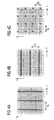
- Fig. 12 shows a block diagram of a transmitter of a OFDM based system utilizing cyclic delay diversity (CDD).
- CDD cyclic delay diversity
- the transmitter comprises a block 1301 for generating pilot sequences which are provided to a multiplexer 1303 for multiplexing same into a data stream provided via a further input of the multiplexer 1303.
- P/S parallel-to-serial converter 1037
- a signal provided by the P/S converter 1037 is then divided into N T identical copies, wherein N T denotes a number of transmitting points.
- a first copy provided via a signal path 1309 is provided to a guard insertion block 1311. After guard interval insertion, a resulting signal is transmitted via a first antenna 1313.
- a second copy provided via a second signal path 1315 is provided to a cyclic delay element 1317. After guard interval insertion, a resulting signal is transmitted via a second transmit antenna 1319. Accordingly, a N T th signal copy is provided via a N T th signal path 1321 to a cyclic delay element 1323. After guard interval insertion, a resulting signal is transmitted via a N T th antenna 1325.
- delay elements in the transmitter inducing antenna specific delays of ⁇ cyc ⁇ samples before guard interval insertion and further transmitter front end processing. Since a signal processing usually performed digitally, the delay elements may be formed to perform cyclic shifts.
- Fig. 13 shows a block diagram of a corresponding receiver of a OFDM based transmission system.
- the receiver comprises a receive antenna 1401 coupled to a guard interval removal block 1403. After removing the guard interval, a resulting signal is provided to a serial to parallel converter 1405 (S/P) having a number of outputs coupled to a FFT transformer 1407.
- the FFT transformer 1407 has a plurality of outputs coupled to a demultiplexer 1409 (DMUX) being operative for de-multiplexing the received versions of the pilot sequences for channel estimation purposes.
- the demultiplexer 1401 is coupled to a channel estimator 1411 and to a detector 1413.
- the detector 1413 is for example operative for equalizing a received signal using channel estimates providers by the channel estimator 1411.
- the receiver front end is unaffected whether CDD is used or not.
- the CDD transmission technique makes the channel more frequency selective since cyclic delays in time domain (after the IFFT at the transmitter) are transformed to phase shifts at the receiver in the frequency domain (after the FFT at the receiver). Therefore, a reliable channel estimation is only possible, when using a standard OFDM receiver, when all sub-carriers are pilot symbols.
- This approach suffers, however, from the problem, that in this case no information transmission is possible during transmission of pilot sequences. In other words, the channel estimation can only be performed at certain time instants, so that a continuous tracking of channel variations cannot be performed. This issue will be addressed later in detail.
- the effective CTF comprises a superposition of a plurality of distinct CTFs associated with the distinct communication channels.
- the distinct CTFs are not superimposed in a straightforward way since each cyclic delay associated with a respective CTF introduces an additional channel characteristic associated with a delay factor introducing additional phase shifts. Therefore, a standard channel estimation unit of a conventional OFDM receiver would fail, when applied to channel estimation within a CDD transmission scenario.
- A. Dammann and S. Kaiser "Standard Conformable Antenna Diversity Techniques for OFDM and its Application to the DVB-T System", in Proc. IEEE Global Telecommunications Conference (GLOBECOM 2001), San Antonio, USA, pp. 3100-3105, Nov. 2001 . it was stated that CDD is fully standard conformable to conventional OFDM receivers, the above-indicated problem clearly shows that, unfortunately, this is in general not the case, which will be elaborated later.
- Fig. 14 demonstrates an influence of CDD on a characteristic of a resulting communication channel.
- the first CTF and the second CTF may be considered as being the CTFs of the first and second antenna, which are both frequency independent.
- pilots For pilot-symbol aided channel estimation (PACE) known symbols (pilots) are inserted with an equidistant spacing of D f sub-carriers.
- Fig. 15 shows a block diagram of a transmitter of a CDD-OFDM system using an individual pilot insertion unit for each antenna.
- a data stream is divided into a plurality of identical copies, wherein each copy is provided to a respective multiplexer 1501 being operative for multiplexing pilot sequences generated by a pilot sequence generator 1503 into a respective copy of the data stream.
- the multiplexer 1501 has a plurality of outputs coupled to an IFFT transformer 1505 of a plurality of IFFT transformers.
- Each transformer 1505 has a plurality of outputs coupled to a parallel-to-serial converter 1507, wherein each parallel-to-serial converter is associated with a corresponding signal path.
- the first signal path 1509 is coupled to a guard insertion block 1511 having an output coupled to a first antenna 1513.
- a second signal path 1515 is coupled via a first delay element 1517 and a guard insertion block to a further transmit antenna of N T transmit antennas.
- a N T th path 1519 of N T paths is coupled by a delay element 1519 and a guard insertion block to an associated transmit antenna.
- the transmitter shown in Fig. 15 demonstrates the increased complexity of the resulting transmitter, when an extra IFFT unit is required for each antenna. This increases complexity conflicts with one of the main advantages of the CDD transmission technique, namely its simplicity, which would be compromised by the requirements of both the transmitter and the receiver.
- the general structure as shown in Fig. 12 comprises a true MISO estimator, i.e. an estimator being suitable to estimate N T CTFs (CTFs) per sub-carrier.
- CTFs CTFs
- SISO single input single output
- the increased complexity is due to the fact that an extra signal processing part is to be used for each transmit antenna path in order to enable the receiver to separate the estimates of the CTFs of the distinct communication channels.
- Us 200270118771 A1 discloses methods and arrangements in a telecommunication system. Pilot signals are concurrently sent in order to increase bandwidth efficiency during a multitude of channel transfer functions in OFDM. Thus, non-interfering channel estimates are obtained. Particularly, the result of an Inverse Discrete Fourier Transform of a training sequence is cyclically rotated by a number of predetermined steps, which is different for each antenna branch.
- US 2003/0043887 A1 discloses a communication system and methods of estimating channel impulse responses therein. Multiple Steiner codes are transmitted as bursts from multiple base stations. Accurate channel estimation is possible through the use of Wiener frequency domain MMSE deconvolution combined with frequency domain spatial decoupling matrices, with quasi-orthogonal pseudo-noise sequences allocated to base stations and their antenna elements.
- US 2002/0101825 A1 discloses a transmitter having an orthogonal sequence source. Antenna branches receive sequences which are delayed with respect to a neighbouring antenna branch. On the receiver side, FIR filters are used. Each FIR filter performs least-squares processing on the baseband demodulated received training signal it receives. To this end, each of FIR filters uses as coefficients the complex conjugates of the base orthogonal sequence.
- the transmitter shown in Fig. 15 demonstrates the increased complexity of the resulting transmitter, when an extra IFFT unit is required for each antenna. This increases complexity conflicts with one of the main advantages of the CDD transmission technique, namely its simplicity, which would be compromised by the requirements of both the transmitter and the receiver.
- the general structure as shown in Fig. 12 comprises a true MISO estimator, i.e. an estimator being suitable to estimate N T CTFs (CTFs) per sub-carrier.
- CTFs CTFs
- SISO single input single output
- the increased complexity is due to the fact that an extra signal processing part is to be used for each transmit antenna path in order to enable the receiver to separate the estimates of the CTFs of the distinct communication channels.
- the present invention is based on the finding that a modulated version of a pilot sequence, which can be a time domain signal or a frequency domain signal, results from a multiplication of a pilot sequence by a modulating sequence. If the modulating sequence represents a carrier wave having a non-zero carrier frequency, then certain values of the pilot sequence are multiplied by the same coefficients of the modulating sequence.
- the effective channel i.e. an effective channel impulse response or an effective channel transfer function
- Each set of selected values comprises superimposed coefficients of different pilot sequences being transmitted through different communication channels, wherein the different communication channels may be represented by channel impulse responses or by channel transfer functions.
- cyclically delaying a time domain signal introduces a coefficient dependent phase shift of a spectral representation of the time domain signal.
- This is equivalent to coefficient-wise multiplying the spectral representation of the time domain signal by a complex or real valued phase shift sequence, which is the modulating sequence, since this operation corresponds to up-converting or down-converting the spectral representation of the time domain signal when the phase shift sequence represents a carrier wave having a non-zero carrier frequency.
- a pilot sequence can also be modulated in frequency domain, when a frequency domain pilot sequence is multiplied by the modulating sequence.
- the modulating sequence can be considered as a phase shift sequence.
- the phase shift sequence +1, -1, +1, -1 etc. introduces a coefficient-wise phase shift by 180°.
- the phase shift sequence (modulating sequence) may be considered as being a sampled version of a sine or a cosine wave.
- the effective channel transfer function can directly be estimated for subcarriers or, in other words, for frequency points which are associated with the same coefficients of the up-converting or down-converting phase shift sequence (modulating sequence).
- every second sub-carrier is associated with values (factors) of the phase shift sequence, which have a positive sign. Accordingly, every other second sub-carrier is associated with every other second value of the phase shift sequence having a negative sign.
- the effective channel transfer function can be estimated by separately estimating coefficients of the effective channel transfer function at frequency points (sub-carriers), which are associated with the same value with respect to a sign and a magnitude of the phase shift sequence (modulating sequence).
- the effective channel transfer function can directly be estimated by separately estimating the effective channel transfer function at frequency points associated with every second sub-carrier (even sub-carriers) and at frequency points associated with every other second sub-carrier (odd sub-carriers).
- the individual channel transfer functions can be reconstructed from the estimates of the effective channel transfer function. To do this, for example, an estimate of the channel transfer function on even sub-carriers and an estimate of the effective channel transfer function on odd subcarriers are interpolated so that N T estimates for each sub-carrier, determining the N T equations, are obtained.
- the cyclic delay corresponds to a half of the OFDM symbol duration, as has been discussed in connection with the embodiment of Fig. 14 .
- the coefficients of the effective channel transfer function are estimated separately for even and odd sub-carriers. In this case, the up-conversion or downconversion effects resulting from multiplying the spectral representation by the coefficients of the phase shift sequence are compensated.
- the effective channel transfer function is estimated from a plurality of estimates of the effective channel transfer function at different sets of frequency points, wherein each set of frequency points is associated with equal coefficients of the phase shift sequence.
- estimating the effective channel transfer function at frequency points associated with a respective set of frequency points provides an estimate of the effective channel transfer function at these frequency points.
- these estimates can be used for e.g. equalizing a spectral representation of a receive signal at those frequency points.
- the estimates of the effective channel transfer function at different frequency points can be merged to a composite estimate of the effective channel transfer function comprising estimates at every considered frequency point.
- a resulting composite estimate of the effective channel transfer function comprises a plurality of coefficients, wherein every second coefficient corresponds to subsequent coefficients of the estimate of the effective channel transfer function at even sub-carriers, and every other second coefficient corresponds to the successive coefficients of the estimate of the effective channel transfer function at odd subcarriers.
- the simple CDD-transmission structure can be maintained even when a time-domain pilot sequence, a copy of which is to be delayed, results from a frequency-time conversion of a multi-carrier sequence in a CDD-OFDM scenario.
- the multi-carrier sequence can be obtained from, for example, assigning successive values of the first pilot sequence in frequency domain (origin sequence) to every D f th sub-carrier of a plurality of successive sub-carriers of a multi-carrier modulation scheme. Therefore, information values can be assigned to the remaining sub-carriers, so that a simultaneous data transmission and pilot transmission for channel tracking is possible. Therefore, the pilot sequence in the time-domain comprises a training part and an information part.
- a further advantage of the inventive concept is, that a simple transceiver structure for CDD-OFDM systems can be maintained which results in the fact that the conventional transmitter and receiver structures as shown in Fig. 12 and 13 for D f >1 can be used. Such larger pilot spacings D f are required to support high velocities of the mobile user for bandwidth efficient and robust channel estimation schemes.
- a further advantage of the present invention results from the fact, that the inventive concept enables using CDD-OFDM transmission systems with arbitrary cyclic delay ⁇ cyc ⁇ . While the range of cyclic delays ⁇ cyc ⁇ which can be supported with conventional channel estimation techniques is limited, arbitrary ⁇ cyc ⁇ can be supported using the inventive scheme.
- constraints for the choice of D f are significantly less stringent when compared to the conventional estimator. This effectively allows to reduce the overhead due to the pilots, i.e. a pilot spacing D f can be increased.
- the inventive concept can also be applied for estimating an effective channel impulse response at a receiver.
- the effective channel impulse response is a frequency-time converted version of the effective channel transfer function. If the pilot sequences are time domain signals, then a multiplication of a pilot sequence by a modulating sequence is equivalent to a coefficient-wise multiplication of time domain samples (values) of the pilot sequence by time domain values of the modulating or phase shift sequence.
- the communication channels are flat fading channels, then the effective channel impulse response can be estimated in the same way in which the effective channel transfer function is estimated, since a flat fading channel does not introduce inter-symbol interferences or introduces negligible inter-symbol interferences.
- a flat fading channel is a channel having a channel impulse response of a short duration which is, for example, smaller than a time interval between two subsequent transmit signal values. For example, the channel impulse response is represented by only one tap representing the channel influence.
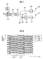
- Fig. 1 shows a block diagram of the inventive channel estimator for estimating an effective channel from a receive sequence.
- the channel estimator comprises a selector 101 being operative for receiving a receive sequence via an input or via a plurality of inputs.
- the selector 101 has N T outputs, wherein N T denotes a number of communication channels or, in other words, a number of transmitting points at a receiver.
- Each output of the selector is coupled to a filter 105 of N T filters, wherein each filter 105 has an output.
- the inventive channel estimator shown in Fig. 1 is operative for estimating an effective channel from a receive sequence.
- the receive sequence is a time domain signal or a frequency domain signal. More specifically, the receive sequence includes a superposition of N T pilot sequences being transmittable from N T transmitting points through N T communication channels to a receiving point. From the N T pilot sequences, N T -1 pilot sequences may be modulated versions of a first pilot sequence as has been explained above.
- the effective channel comprises a superposition of N T channels extending from N T transmitting points to the receiving point, wherein the receiving point comprises the inventive channel estimator. If the receive sequence is a time domain signal, then the effective channel is an effective channel impulse response comprising a superposition of N T channel impulse responses associated with N T distinct communication channels. Accordingly, if the receive sequence is a frequency domain signal, then the effective channel is an effective channel transfer function comprising a superposition of N T channel transfer functions associated with the N T communication channels.
- the selector 101 is operative for providing N T sets of selected values, wherein each set of selected values comprises selected values associated with the same value (factor) of a modulating sequence or, in other words, of a phase shifting sequence modulating the first pilot sequence.
- the inventive selector 101 is operative for providing a m th set of selected values of N T sets of selected values by selecting every (DN T ) th value from a set of values comprised by the receive sequence or, in other words, form the receive sequence, starting with a m th value in the set of values, wherein D denotes a pilot spacing.
- the receive sequence is a time domain signal comprising a superposition of a plurality of time domain transmit signals.
- a first transmit signal comprises the first pilot sequence
- the other transmit signals comprise modulated versions of the first pilot sequence.
- D>1 then the subsequent values of the first pilot sequence are assigned to every D th value of the first transmit signal and the other values of the transmit signal may be, for example, information values.
- the selector is operative for selecting, for example, the m th subset starting with the m th value in the set of values.
- the index m is a numbering index providing information on a beginning of the m th set to be selected.
- Each of the N T sets of selected values is filtered by an associated filter 105 in order to provide the estimate of the effective channel.
- the filter 105 for filtering the m th set of selected values is formed to provide a m th set of filtered values comprising an estimate of the effective channel at points associated with the m th set of filtered values, wherein the points may be time instants for the case of a time domain receive sequence or frequency points (sub-carriers) in the case of a frequency domain receive sequence.
- each of the filter 105 is operative for providing an estimate of the effective channel, which can be an estimate of the effective channel transfer function or of the effective channel input response.
- the N T filter 105 provide N T estimates of the effective channel at different points, i.e., at different frequency points or at different time-points.
- the receive sequence comprises a number of subsequent receive sequence values, wherein every D th receive sequence value comprises pilot information determined by a value of the first pilot sequence.
- the filter 105 is an interpolation filter being operative for interpolating between subsequent values in the m th set of selected values comprising pilot information for providing a m th interpolated set of values comprising interpolated values between subsequent values of the m th set of selected values.
- the filter 105 associated with a m th signal path determined by the m th set of selected values interpolates between the subsequent values in the, which are used as sampling points or supporting points for interpolation, in order to provide the interpolated values.
- the filter 105 is operative for providing the m th interpolated set of selected values as the m th set of selected values.
- the other filter 105 operate in the same way.
- the filter 105 bay be operative for providing D-1 interpolated values between subsequent values in each set of selected values.
- the filter 105 associated with the m th set of selected values is operative for providing D-1 interpolated values between subsequent values in the m th set of selected values.
- a length of each set of selected values is extended to a length of the receive sequence, so that each filter 105 provides an estimate of the effective channel for each receive sequence value, or in other words, for each point, wherein each estimate of the effective channel of the N T estimates of the effective channel is provided by performing an interpolation scheme applied to different set of selected values.
- the filter 105 are low pass interpolation filter or a polynomial interpolation filter or a Wiener interpolation filter.
- the filter 105 can be low-pass filter.
- the receive sequence may be a time domain sequence.
- the effective channel is an effective channel impulse response comprising a superposition of N T channel impulse responses, wherein the receive sequence comprises a received version of a transmit sequence, for example, of the first transmit sequence mentioned above.
- the transmit sequence results from assigning subsequent values of the first pilot sequence to every D th value of the transmit sequence, wherein D denotes a time interval between subsequent values of the first pilot sequence in the transmit sequence, as has been explained above.
- each value of the first pilot sequence is followed by D-1 transmit values comprising, for example, an information to be transmitted, wherein the values of the first pilot sequence are pilot information, i.e., an additional information used for channel estimation.
- the selector is operative for providing the m th set of selected values starting with the m th value being receivable at a m th time instant, and selecting every (DN T ) th value being receivable at every (DN T ) th time instant.
- the time domain receive sequence may be a serial data scream which is processed in a sequential manner by the selector 101. Therefore, the selector 101 may comprise one input for receiving the receive sequence and N T outputs for providing the N T sets of selected values, wherein the m th set of selected values is provided via a m th output of the N T outputs.
- the receive sequence in time domain may be a parallel data stream, when, before selecting, a serial to parallel converter is applied.
- the selector 101 comprises a plurality of inputs, wherein each input is associated with a single value of the receive sequence.
- the N T filter coupled to the N T outputs of the selector are interpolation filter being operative for generating D-1 interpolated values between subsequent values in the sets of values, wherein the N T sets of interpolated values comprise N T estimates of the effective channel impulse response.
- the filter 105 may be operative only for e.g. low-pass filtering the selected sets of values without performing an interpolation operation in order to suppress, for example, channel noise.
- the inventive channel estimator may further comprise means for calculating the N T channel impulse responses from the N T estimates of the effective channel impulse response by solving, for example, N T algebraic equations being determined by the N T estimates of the effective channel impulse response comprising a superposition of the N T channel impulse responses.
- the effective channel transfer function 1601 comprises the channel transfer functions in a superimposed manner. In the case of flat fading channels, the same physical effect can be observed in time domain, so that an effective channel impulse response can be observed. Therefore, the superimposed channel impulse responses comprised by the effective channel impulse response can be calculated in exactly the same way.
- the channel impulse responses may be obtained from N T estimates of the effective channel impulse response, wherein the estimates are interpolated estimates.
- the estimates of the effective channel impulse response provided by each of the filter 105 are interpolated, so that interpolated estimate values of the effective channel impulse responses are provided for each time instant associated with a receive sequence value. Therefore, the inventive means for calculating the N T channel impulse responses uses N T interpolated estimates of the effective channel impulse response to provide channel impulse response values associated with a communication channel for all time instants or, in other words, for all time points.
- the receive sequence may be a frequency domain sequence obtained, for example, from a time-frequency conversion of a received time domain signal.
- the effective channel is an effective channel transfer function, wherein the receive sequence comprises a received version of a transmitted multi-carrier sequence associated with a multi-carrier transmission scenario, for example, OFDM.
- the multi-carrier sequence comprises subsequent values which are assigned to subsequent sub-carriers of a multi-carrier modulation scheme.
- the remaining D-1 values of the multi-carrier sequence between a first value of the first pilot sequence and a second value of the pilot sequence are information signal values.
- the inventive selector 101 is operative for providing the m th set of selected values starting with the m th value being associated with a m th sub-carrier, and for selecting every (DN T ) th value being associated with every (DN T ) th sub-carrier.
- the receive sequence in frequency domain may be a parallel data stream.
- the inventive selector 101 comprises a number of inputs associated with a number of receive sequence values.
- the N T filter 105 coupled to the N T outputs of the selector 101 are operative for providing N T sets of filtered values, wherein each set of filtered values comprises an estimate of the effective channel transfer function at frequency points determined by sub-carriers associated with the respective set of filtered values.
- the selector 101 outputs N T sets of selected values as serial data, i.e. the m th set of selected values is a serial data stream.
- the filter 105 are operative for filtering the N T sets of selected values in order to provide estimates of the effective channel transfer function at frequency points determined by the sub-carriers associated with the corresponding set of filtered values.
- the filter 105 associated with the m th set of selected values is operative for filtering the m th set of selected values in order to provide a m th set of filtered values comprising an estimate of the effective channel transfer function at frequency points determined by sub-carriers associated with the m th set of filtered values, i.e. at frequency points determined by every D f N t th sub-carrier starting with the m th sub-carrier.
- the N T filter are low pass filter applied to every set of selected values.
- the N T filter are operative for reducing channel noise.
- the N T filter can be low pass interpolation filter being operative for performing a polynomial interpolation or a Wiener interpolation.
- the N T filter are interpolation filter for interpolating in frequency direction.
- the m th set of selected values is associated with successive frequency points associated with every D f N T sub-carrier.
- the m th filter is operative to provide the m th set of filtered values having intermediate values associated with intermediate frequency points between the successive frequency points by interpolating on the basis of filtering.
- the inventive filter performs an interpolation at frequency points associated with the same valuing factor, e.g. with the same phase shift sequence value.
- the inventive filter in the case of interpolation, reference is made again to Fig. 14 for the case, that the channel transfer function for odd sub-carriers can only be obtained at frequency points associated with every fourth sub-carrier.
- the inventive filter is operative for providing intermediate values at frequency points associated with every second even sub-carrier.
- the N T filter can be interpolation filter for interpolating in time direction.
- the m th filter 105 associated with the m th set of selected values is operative for interpolating between corresponding values of the m th set of selected values or the m th set of filtered values at a first time instant and values of the m th set of selected values or of the m th set of filtered values at a second time instant to provide the m th set of selected values at an intermediate time instant between the first time instant and the second time instant.
- a time interval between the time instants is determined by time instants at which the signals being transmittable from a transmitter contain training information.
- the transmitter is operative to transmit the pilot sequences at every D t time instant or every D t signal frame, for example, OFDM symbol.
- the inventive interpolation filter 105 perform time interpolation so that estimates of the effective channel transfer function can be obtained at intermediate time instants. This is, for example, necessary for tracking a characteristic of a time-variant communication channel, where corresponding coefficients of the effective channel transfer function vary in time due to, for example, a non-zero velocity of a mobile receiver.
- the interpolation can be performed for every set of selected values before filtering. However, the interpolation can also be performed after filtering. Additionally, the filtering operation and the interpolation operation can be performed simultaneously.
- the inventive filter 105 can be operative for performing both: interpolation in time direction and interpolation in frequency direction.
- the filter are operative for performing time interpolation first in order to provide time interpolated values which are, in a next filtering step, used for interpolating in frequency domain.
- the inventive filter may be operative to perform time interpolation after frequency interpolation.
- the inventive filter may be operative for interpolating in time and in frequency direction simultaneously. In this case, the inventive filter are operative for performing 2D filtering.
- Fig. 2 shows a block diagram of the inventive channel estimator in accordance with a further aspect of the present invention.
- the inventive channel estimator shown in Fig. 2 comprises a time-frequency converter 201 having an input and a plurality of outputs coupled to the selector 101.
- the time-frequency converter 201 is operative for time-frequency conversion of a time domain signal in order to obtain a spectral representation of the time domain signal which is the receive sequence.
- the time domain signal corresponds to a cyclic delay diversity transmission scenario, wherein N T time domain pilot sequences are transmittable from N T distinct transmitting points through N T distinct communication channels to a common receiving point, where N T -1 time domain pilot sequences are cyclically delayed versions of a first time domain pilot sequence being transmittable from a first transmitting point.
- the first time domain pilot sequence results, for example, from a frequency time conversion of the previously mentioned multi-carrier sequence comprising the first pilot sequence in frequency domain.
- the values of the first pilot sequence in frequency domain are assigned to every D th sub-carrier of the multi-carrier sequence, wherein D is a pilot spacing is equal to or greater than 1.
- the N T -1 time domain pilot sequences have spectral representations, which are modulated versions of the first pilot sequence in the frequency domain.
- cyclically delaying a time domain signal is equivalent to a multiplication of a spectral representation of the time domain signal by a modulating sequence or, in other words, by a phase shift sequence.
- the N T time domain pilot sequences are transmitted through N T communication channels to a receiving point comprising the inventive channel estimator. Therefore, the time domain signal comprises a superposition of N T time domain pilot sequences being combined with channel impulse responses associated with N T distinct communication channels.
- the receive sequence in frequency domain comprises a superposition of N T pilot sequences (in frequency domain) being combined with channel transfer functions associated with the N T distinct communication channels.
- the selector 101 is operative for providing N T sets of selected values, wherein each set of selected values corresponds to sub-carriers being associated with the same factor (phase shift factor or modulating factor).
- the inventive selector 101 is operative for selecting every (DN T ) th value from the sets of values provided by the time-frequency converter 201 starting with a m th value in the set of values.
- the values in the set of values provided by the time-frequency converter 201 are associated with numbering indices, so that the selector 103 is operative for providing the m th set of selected values by selected values being associated with every (DN T ) th numbering index.
- the time-frequency converter 201 can be a Fourier transformer being operative for performing a discrete Fourier transform etc. in order to obtain the receive sequence with the spectral representation of the time domain signal. Moreover, in the case of OFDM transmission, the time-frequency converter is the FFT transformer applied for demodulation.
- the inventive selector 101 receives the spectral representation of the time domain signal and provides on a basis thereof N T sets of selected values as serial data streams. However, the inventive selector 101 may provide the N T sets of selected values as parallel data streams. In this case, the selector 101 has a number of outputs corresponding to the number of outputs of the time-frequency converter, wherein the outputs providing the m th set of selected values are grouped together. Since the filter 105 may be designed as a digital filter, a filtering operation can be performed on serial or parallel data.
- the first pilot sequence (origin pilot sequence) at the transmitter which is a frequency domain sequence, may comprise a scrambling sequence.
- the first pilot sequence results from multiplying a further frequency domain pilot sequence in frequency domain (further origin pilot sequence) by the scrambling sequence in order to, for example, additionally protect signals to be transmitted through the plurality of communication channels from channel influences.
- the scrambling sequence additionally modulates the further origin pilot sequence.
- the time-frequency converter 101 comprises means for multiplying every D f th value of the spectral representation of a time-domain receive signal by complex conjugated versions of successive values of the scrambling sequence to obtain a descrambled sequence as the spectral representation of the receive signal.
- the means for multiplying comprises a multiplier assigned to every D f th value of the spectral representation of the time-domain receive signal in order to perform the multiplication.
- the means for multiplying may be operative for multiplying every D f th value of the spectral representation by inverse successive values of the scrambling sequence, which corresponds to a division operation.
- the origin pilot sequence values are assigned to every D f th sub-carrier of the multi-carrier sequence starting with a k th sub-carrier of the multi-carrier sequence.
- a first origin pilot sequence value from the set of origin pilot sequence values may be assigned to any sub-carrier of the multi-carrier sequence, for example, to a fifth sub-carrier.
- the selector is operative to provide a first set of selected values by selecting every D f N T th value from the set of values provided by the time-frequency converter 101 (spectral representation of the receive signal) starting with a k th value of the spectral representation of the time-domain receive signal.
- the sub-carrier index k provides an information on a first sub-carrier containing pilot information to be selected.
- the inventive channel estimator may further comprise means for providing information on the index k.
- This information can be provided from the transmitter via an additional information channel.
- this information can be pre-stored in accordance with a pre-agreed pilot grid scenario.
- the N T filter provide estimates of the effective channel transfer function at different frequency points.
- the different estimates can directly be applied for equalizing, decoding etc.
- the channel estimator may further comprise a composer for composing the estimates of the effective channel transfer function provided by the N T filter at different frequency points to obtain an estimate of a composite effective channel transfer function, as has been described above.
- the inventive channel estimator comprises two filter, wherein a first filter is operative for providing an estimate of the effective channel transfer function at frequency points associated with odd-numbered sub-carriers, and wherein a second filter is operative for providing an estimate of the effective channel transfer function at frequency points associated with even-numbered sub-carriers, or vice versa.
- the inventive composer is operative for composing the composite effective channel transfer function by assigning values of the effective channel transfer function at frequency points associated with odd-numbered subcarriers to odd-numbered sub-carriers of the composite effective channel transfer function and by assigning values of the effective channel transfer function (or of the estimate thereof) at frequency points associated with even-numbered sub-carriers to even-numbered sub-carriers of the composite effective channel transfer function.
- the inventive composer is operative for interlocking the estimates of the effective channel transfer function to obtain the composite effective channel transfer function or an estimate thereof.
- the inventive channel estimator may further comprise means for removing an influence of the effective channel transfer function or of the effective channel impulse response, wherein the means for removing the influence may be, for example, an equalizer.
- the means for removing the influence of the effective channel transfer function is coupled to the plurality of outputs of the time-frequency converter in order to receive the spectral representation of the receive signal containing the influence of the effective channel transfer function.
- the means for removing further comprises a further plurality of inputs, to which outputs of the filters are coupled in order to provide the estimate of the effective channel transfer function to the means for removing.
- the means for removing can be operative for receiving the estimate of the composite effective channel transfer function provided by the inventive composer mentioned above.
- the means for removing has an output for outputting a processed signal, wherein the processed signal may be an equalized version of the spectral representation of the receive signal provided by the time-frequency converter.
- the inventive channel estimator is used in a OFDM receiver.
- the means for removing the influence may be a frequency domain equalizer or a frequency domain decoder, for example a maximum likelihood decoder being operative for decoding the spectral representation of the receive signal using the estimate of the effective channel transfer function.
- the inventive channel estimator may comprise means for calculating the N T channel transfer functions from the N T estimates of the effective channel transfer function by solving, for example, a set of algebraic equations being determined by the estimates of the effective channel transfer function, as has been shown in connection with the embodiment of Fig. 14 and as has been explained in connection with the effective channel impulse response.
- the inventive concept will be described with respect to the receive sequence in frequency domain by the way of example only. It is to be noted, that the same considerations also apply in the case of a receive sequence in time domain.
- the first pilot sequence which is a frequency-domain sequence
- the time-domain pilot sequences will be referred to as pilot sequences.
- the inventive exploiting of the DFT (discrete Fourier transform) properties of CDD the structure of the transmitter unit as shown in Fig. 12 can be retained, while the receiver can still fully utilize a MISO channel estimation unit.
- the inventive concept establishes a virtual MISO pilot grid with the conventional CDD-OFDM transmitter from Fig. 12 .
- the term "virtual MISO pilot grid" describes the resulting spectral representations of the pilot sequence after introducing cyclic delays, so that each channel transfer function of the plurality of channel transfer functions experiences its own, unique training sequence.
- the inventive concept is based on the DFT property that cyclic delays are translated to phase shifts by the DFT operation. This can be exploited if the cyclic delays ⁇ cyc ⁇ are known to the receiver, since the receiver will observe transmit antenna dependent phase shifts of the received signal. If the system parameters are properly chosen, a set of phase shifted pilot sequences can be generated by the antenna dependent cyclic delay operation.
- the inventive idea is based on a consideration of the oscillating sign of H (2) between even and odd sub-carriers as a phase shifted pilot sequence, which can be utilized as side information for the channel estimator.
- a cyclic delay of ⁇ cyc ⁇ ⁇ - 1 ⁇ T / N T .
- both H (2 i / T ) and H ([2 i + 1] / T ) are also frequency flat, drawn as straight lines in Fig. 14 .
- the number of non-zero taps is typically smaller or equal to the maximum delay of the channel, Q 0 ⁇ Q . It is assumed that the Q 0 channel taps and all antennas are mutually uncorrelated.
- the channel taps h q ⁇ t are zero-mean complex independent identically distributed (i.i.d.) Gaussian random variables. Due to a motion of the vehicle (mobile transmitter or mobile receiver) h q ⁇ t will be time-variant caused by the Doppler effect.
- the q th channel tap h q ⁇ t is a wide sense stationary (WSS) Gaussian process being band-limited by the maximum Doppler frequency ⁇ max .
- CIR channel impulse response
- the channel transfer function mentioned above is the Furrier transform of the CIR h ( ⁇ ) (t, ⁇ ).
- the guard interval is longer than the maximum delay of the channel, i.e. N GI ⁇ Q , where Q ⁇ Q 0 denotes the total number of channel taps, the orthogonality at the receiver after OFDM demodulation is maintained and the received signal after OFDM demodulation is obtained.
- the introduced channel model has been introduced for multiple input single output systems. Assuming the fading at the receiver antennas is mutually uncorrelated, the channel estimation will be performed independently for each antenna. Hence, an extension to a multiple input multiple output (MIMO) system is straight forward since the channel estimation is performed on each receive antenna separately.
- MIMO multiple input multiple output
- Fig. 12 there is a common signal stream for all transmit antennas until after the parallel to serial conversion (PS), i.e. only one IFFT is required.
- PS parallel to serial conversion
- ⁇ cyc ⁇ is a design parameter within the range [0, N FET / N T ].
- X l , i ⁇ represents the transmitted frequency domain signal of transmit antenna ⁇ . It is to be noted that X l , i ⁇ does exist only virtually, it is the equivalent signal which would be obtained by induc
- the guard interval is the form of a cyclic prefix is added, which is typical for OFDM modulation.
- the signal is digital to analog converted (D/A), up-converted to the radio frequency (RF) carrier frequency and transmitted over a mobile radio channel.
- D/A digital to analog converted
- RF radio frequency
- the guard interval is removed, and an IFFT operation transforms the signal into the frequency domain, i.e. the sub-carrier level.
- OFDM demodulation pilot symbols are de-multiplexed and fed to the inventive channel estimation unit (channel estimator).
- the received signal consists of N T signals, as is described by one of the above equations.
- the resulting SISO channel model for CDD-OFDM i.e. the resulting SISO channel being observed by the receiver will be examined.
- phase term of the resulting CTF is determined by the propagation delays ⁇ q ⁇ and the cyclic delay parameter ⁇ cyc . It is interesting to note that ⁇ cyc is independent of the physical channel, a fact which can be exploited to make CDD-OFDM channel estimation more efficient.
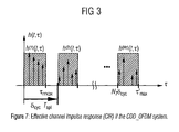
- Fig. 3 shows an effective channel impulse response (a realisation of h ( t, ⁇ )) of a CDD-OFDM system.
- the effective channel impulse response comprises N T channel impulse responses, wherein N T -1 channel impulse responses are delayed with respect to a first channel impulse response.
- each tap as well as each transmit and receive antenna are mutually uncorrelated.
- the correlation in time direction is independent of ⁇ .
- R HH ⁇ ⁇ ⁇ l ⁇ R HH ⁇ ⁇ ⁇ l ⁇ T sym R hh ⁇ ⁇ ⁇ l ⁇ T sym
- the frequency correlation function of the resulting CTF is of interest, which is the sum of the N T correlation functions. Furthermore, each frequency correlation function is phase shifted according to the cyclic delay of the respective transmit antenna.
- pilot-symbol aided channel estimation PACE
- known symbols pilots
- pilots pilots
- 1.
- the received signal Y l,i is obtained.
- G is the sub-set of the OFDM frame containing the pilots.
- Figures 4a, 4b, and 4c show possible realizations of pilot grid structures.
- one possibility of realizing a pilot grid is to transmit one OFDM symbol containing only pilots followed by D t -1 data symbols. This scheme is applicable for channels with little time variations, as is observed in an indoor environment. In this case, interpolation in frequency direction is not necessary.
- Such a pilot grid structure is employed in the WLAN standards HIPERLAN/2 and 802.11a.
- Fig. 4b another possibility of realizing a pilot grid is to transmit the pilots on reserved sub-carriers continuously.
- This scheme can support mobility but requires interpolation in frequency direction.
- a more bandwidth efficient solution is to employ a scattered pilot grid, as is shown in Fig. 4c .
- a scattered pilot grid is characterized by the spacing D f in frequency direction and D t in time direction, respectively.
- the first step in channel estimation process is to remove the modulation of pilot symbols, which can be introduced by the previously mentioned scrambling sequence.
- the channel may be quasi-static, i.e. channel variations within one OFDM frame can be neglected.
- a pilot grid transmitting one OFDM training symbol in the beginning of the frame may be transmitted, as is indicated in Fig. 4a .
- Channel estimation is performed once per frame for each sub-carrier. These estimates are used for the entire frame. In R.
- a separate filter is required for each sub-carrier i and each OFDM symbol 1 within one frame.
- Such a 2D estimator structure may be, however, too complex for practical implementation.
- separating the use of time and frequency correlation can be performed.
- This combined scheme termed double one dimensional (2 ⁇ 1D) PACE uses separate Wiener filters, one in frequency direction and one in time direction.
- 2 ⁇ 1D PACE is motivated by the fact that the 2D correlation function can be written in a product form, i.e., the correlation function in frequency and time are independent.
- the Wiener interpolation filter minimize the mean squared error (MSE) between the desired response H l,i and the observation, i.e. the received pilot symbols. This means that knowledge about the channel statistics is required. In contrast, low pass interpolation filters and polynomial interpolators do not assume any knowledge of the channel statistics.
- FIR filtering is not the only way to perform channel estimation.
- Another possibility is to transform the received pilot sequence to a transformation domain. An additional processing may be performed in the transformation domain. A resulting processed sequence is subsequently transformed back to the original domain in order to yield an estimate of the entire OFDM symbol.
- the transform may be a time-frequency transform, for example a Fourier transform, or a singular value decomposition (SVD).
- CDD-OFDM does not have any effects on pilot spacing in time direction D t .
- CDD effectively extends the maximum delay of the channel, which calls for a denser pilot spacing D f , if a conventional SISO channel estimator is used.
- D f becomes significantly smaller. This means that more pilots are required, which degrades the spectral efficiency of the system.
- the OFDM system parameters are chosen such that the maximum delay of the channel does not exceed the guard interval duration, ⁇ max ⁇ T GI .
- the OFDM symbol duration T N FFT T spl is chosen 5 to 20 times larger than T GI to provide a spectrally efficient system.
- ⁇ max can be upper bounded by ⁇ max ⁇ T GI ⁇ N FFT T spl / 5 ⁇
- the present invention further provides a virtual MISO pilot grid which can preferably be used with the conventional CDD-OFDM transmitter from Fig. 12 .
- a virtual MISO pilot grid which can preferably be used with the conventional CDD-OFDM transmitter from Fig. 12 .
- phase term appearing in the above equations, e - j ⁇ ⁇ ( ⁇ ) defines the previously mentioned phase shift sequence.
- X ⁇ l ⁇ , i ⁇ ⁇ has the form of a phase shifted pilot sequence
- known channel estimation techniques for OFDM with multiple transmit antennas can be applied to channel estimation.
- Channel estimation schemes for OFDM with multiple transmit antennas are described, for example, in Y. Li, N. Seshadri, and S. Ariyavisitakul, "Channel Estimation for OFDM Systems with Transmitter Diversity in Mobile Wireless Channels," IEEE Journal of Selected Areas on Communications, vol. 17, pp. 461-470, Mar. 1999 .
- the demodulated pilots are used.
- This case corresponds to the inventive scenario where the inventive base band filter simultaneously performs filtering and down conversion.
- a processing of the base band representations of the channel transfer functions is performed by compensating the influence of D f as has been described above.
- an up conversion can be performed, i.e., the processed channel transfer functions are multiplied by associated phase shift sequences.
- the complexity of the estimator is approximately N T M f multiplications per sub-carrier, which results in about N T times the complexity of a comparable SISO estimator. This is motivated by the fact that N t signals which are in general mutually independent have to be estimated.
- 2 ⁇ 1D PACE algorithms can be applied if a scattered pilot grid is used.
- 2D and 2 ⁇ 1D PACE algorithms can be applied if a scattered pilot grid is used.
- the pilot spacing of MISO-OFDM channel estimator is bounded by D f ⁇ N T ⁇ ⁇ max / T ⁇ 1
- the overhead due to pilot symbols increases proportionally with the number of transmit antennas.
- the overhead due to the pilot symbols for the MISO estimator becomes less if ⁇ cyc T spl > ⁇ max .
- MISO channel estimation is more efficient in terms of pilot overhead.
- the virtual MISO pilot sequences X ⁇ l ⁇ , i ⁇ ⁇ are dependent on ⁇ cyc and the pilot spacing D f . So, if both ⁇ cyc and D f are fixed, it may not be possible to estimate the N T different channel. The reason is that each transmit antenna's channel requires a unique pilot sequence in order to distinguish the N T channels. In other words, phase ambiguities must be avoided.
- the estimator performance is dependent on pilot sequence design. Moreover, the estimator performance is optimum if the periodicity of the phase shifted pilot sequences X ⁇ l ⁇ , i ⁇ ⁇ is N T . This means that ⁇ ( ⁇ ) mod 2 ⁇ has exactly N T constellation points.
- the above equation states that ⁇ ( ⁇ ) and multiples of 2n are within the set P so an equivalent notation is ⁇ ( ⁇ ) mod 2 ⁇ ⁇ P.
- the present invention provides in accordance with a further aspect a concept for a simplified channel estimation for CDD-OFDM with maximum cyclic delay.
- the induced phase term of CDD has become independent on n, since any terms dependent on n are multiple of 2n and can thus be neglected.
- ⁇ (m, ⁇ ) can be regarded as a constant with respect to n within the n th set.
- the basic inventive idea associated with the simplified channel estimation scheme is not to estimate the channel transfer function for each transmit antenna, H l , i ⁇ separately, but to estimate G l , n m separately for each set, in the way that only the pilots, which are also within the m th set are used.
- the estimation of G l , n m for set n is equivalent to estimate a SISO channel. The only difference is that only pilots are used which fall into the set m. Fortunately, a subset of pilots denotes by G ⁇ l , n m will be within each set if the above equation is satisfied.
- the maximum pilot spacing of the inventive technique is according to the sampling theorem D f ⁇ T N T max ⁇ ⁇ max ⁇ where max ⁇ ⁇ max ⁇ , is the maximum delay of the N T superimposed channel G l , n m , which is determined by the total maximum of the individual maximum channel delays. Assuming that all channels have a similar maximum delay ⁇ max ⁇ ⁇ max ⁇ , the max operation above may be omitted.
- pilot positions for set m are determined by 250.
- 251 for the pilots 252 as 253 with 254 is obtained.
- a 1D, 2D or 2 ⁇ 1D SISO channel estimator, as described above, respectively, with pilot spacing 255 can be applied.
- the inventive channel estimator operates as follows. Firstly, the modulation of the pilot symbols is removed.
- Channel estimation of a symbol belonging to set m is performed by only using pilots which are also in that set. This is the difference to conventional SISO channel estimation.
- the computational complexity of the inventive algorithm for the 1D estimator is M f multiplications per sub-carrier, where M f is the filter order of the inventive filter. This is the same as for the conventional SISO estimator.
- the MISO estimator described above has a N T times higher complexity.
- the performance of the inventive estimator is dependent on the chosen estimator and on the channel characteristics. However, it is to be noted that if the power delay profiles of all N T channels are similar, N T adjacent sub-carriers become de-correlated, as has been shown above, which corresponds t the grouping of the sets. So, nothing is lost if pilots are neglected which belong to adjacent sets since they are uncorrelated anyway. In this case, the inventive estimator approaches the performance of the MISO estimator at significantly lower computational cost.
- the simplified channel estimator scheme provides directly an estimate of the effective channel transfer function.
- Fig. 5 shows an inventive pilot grid structure for CDD-OFDM with two transmit antennas.
- pilots occupy even and odd sub-carriers, respectively.
- pilots are used which are located on even and on odd sub-carriers, respectively.
- the pilot spacing D f must be odd.
- the present invention additionally provides a concept for relaxing the requirements for D f .
- the transmitter can be slightly modified in accordance with a further aspect of the present invention.
- Fig. 7 shows a block diagram of an inventive CDD-OFDM transmitter which can support even pilot spacings D f .
- the inventive CDD-OFDM transmitter of Fig. 7 comprises a pilot generator 701 coupled to a multiplexer 703.
- the multiplexer 703 has an input for receiving data sequence and a plurality of outputs coupled to an IFFT transformer 705.
- the IFFT transformer 705 has a plurality of outputs coupled to a parallel-to-serial converter 707 (P/S) .
- a signal path determined by an output of the parallel-to-serial converter 707 is divided into a first signal path 709 and a second signal path 711.
- the first signal path 709 is coupled to a guard insertion block 713 having an output coupled to a first transmit antenna 715.
- the second signal path 711 is coupled to an input of a multiplier 717, the multiplier 717 having a further input 719 and an output coupled to a delay element 721.
- the delay element 721 is coupled via a guard insertion block 723 to a second transmit antenna 725.
- the inventive transmitter shown in Fig. 7 differs from the CDD-OFDM transmitter shown in Fig. 12 by a multiplication with an antenna dependent complex constant ⁇ 1 ⁇ provided to the further input 719 of the multiplier 717.
- the antenna dependent complex constant changes once every D T OFDM symbols.
- even and odd sets are shifted by one sub-carrier every D T OFDM symbols, which effectively is having the same effect as a shift of the pilots by D 0 .
- ⁇ 1 ⁇ is a constant for D T OFDM symbols.
- ⁇ 1 2 only negates the input sequence on the second antenna, that means that a sign of input sequence values is converted.
- Fig. 9 shows a block diagram of the inventive apparatus for generating N T pilot sequences.
- the apparatus comprises an assigner 901 having a first input 903 and a second input 905.
- the assigner 901 has a plurality of outputs coupled to a frequency-time converter 907.
- the frequency-time converter 907 has an output coupled to a means 909 for providing a ⁇ th copy of a converted sequence provided by the frequency-time converter 907.
- the means for providing the ⁇ th copy is operative for dividing a signal path defined by the output of the frequency-time converter 907 into a plurality of signal paths, wherein in Fig. 9 , by the way of example only, a first signal path 911 and a ⁇ th signal path 913 are depictive.
- the ⁇ th signal path 913 is coupled to a means 915 for cyclically delaying (delay element) which has an output.
- the apparatus shown in Fig. 9 is operative for processing an information signal provided via the second input 905 and the origin pilot sequence provided via the first input 903 in accordance with a cyclic delay diversity scheme, wherein both sequences are depicted in Fig. 9 .
- a cyclic delay diversity scheme wherein both sequences are depicted in Fig. 9 .
- the subsequent values of the origin pilot sequence are assigned to every D f th sub-carrier, wherein the successive values of the information sequence are assigned to the remaining sub-carriers.
- the inventive assigner 901 performs a multiplexing operation.
- the assigned sequence is provided via the plurality of outputs of the assigner 901. After time-frequency conversion and an optional parallel-to-serial conversion, a plurality of copies of the converted sequence are provided.
- inventive apparatus shown in Fig. 9 may also be operative for assigning only subsequent values of the origin pilot sequence.
- D f 1.
- the converted sequence is common to all N T pilot sequences.
- the inventive apparatus is operative for providing a plurality of pilot sequences from a single origin pilot sequence using a single time-frequency converter, which can be for example a single Fourier transformer, for example an IFFT transformer being operative for performing a single IFFT transform.
- the means 909 for providing the ⁇ th copy may be operative for providing a plurality of copies of the converted sequence, as is depicted in Fig. 9 .
- the means 909 for providing the ⁇ th copy may be operative for providing the converted sequence for a first copy of the converted sequence as a first pilot sequence of N t pilot sequences and, simultaneously, for providing the ⁇ th copy of the converted sequence to be used for providing the ⁇ th pilot sequence.
- the N T pilot sequences are based on the same origin pilot sequence or, in other words, are derived from the same converted sequence.
- the copies of the converted sequence are processed in such a way, that spectral representations of the resulting pilot sequences occupy different spectral regions, as has been mentioned above.
- a spectral representation of the ⁇ th pilot sequence occupies a band-pass spectral region
- the spectral representation of the first pilot sequence occupies a base band spectral region or a further band-pass region, so that both spectral regions do not overlap.
- this characteristic can be exploited by the inventive channel estimator, wherein a simple band-pass filter applied for filtering the spectral representations may be used in order to obtain channel estimates.
- the presented invention applies predetermined cyclic delays.
- different pilot spacings D f can be used.
- the inventive means 915 for cyclically delaying is operative for cyclically delaying the ⁇ th copy of the converted sequence by a delay value which is dependent on D f , or wherein the assigner is operative for using a pilot spacing being dependent on the cyclic delay value.
- D f depends on the delay factor.
- the delay factor or D f are chosen such that, for example a spectral representation of the ⁇ th pilot sequence is multiplied by a phase shift sequence, for example +1, -1 etc., which introduces the up-converting effect described above.
- the delay factor is fixed.
- the inventive assigner 901 may be operative for choosing D f such that, as a result, a spectral representation of the ⁇ th pilot sequence is, for example, up-converted to the band-pass spectral region.
- the inventive means 915 for cyclically delaying may operative for delaying the ⁇ th copy of the converted sequence such that a spectral representation of the ⁇ th pilot sequence occupies, by the way of example only, the previously mentioned band-pass spectral region.
- the inventive assigner 901 and the inventive means 915 for cyclically delaying may cooperate with each other.
- the assigner 901 and the means 915 for cyclically delaying may adjust D f and the delay value such that the desired effect is introduced even if possible values for D f and possible values for the cyclic delay value are limited.
- D f may be even, which is associated with the above mentioned problems.
- the inventive assigner 901 may be operative for assigning subsequent values of the origin pilot sequence to every D f th sub-carrier starting with, for example, an odd-numbered sub-carrier at a time-instant, at which pilots are transmitted, and for assigning the subsequent values of the origin pilot sequence to every D f th sub-carrier starting with an even-numbered sub-carrier at a following time-instant, at which further are transmitted, or vice versa.
- the inventive assigner 901 introduces a numbering shift, so that the pilots are assigned to even and odd sub-carriers at different time-instants.
- the means 909 for providing the ⁇ th copy may comprise the multiplier 717 for multiplying the ⁇ th copy of the converted sequence by a multiplying factor to provide a multiplied copy as the ⁇ th copy of the converted sequence.
- the multiplying factor may be antenna dependent, i.e., dependent on a numbering index associated with, for example, the ⁇ th copy.
- the numbering index may be equal to ⁇ .
- the delay element 915 is, as has been explained above, operative for cyclically delaying the multiplied copy in order to provide the ⁇ th pilot sequence.
- the delay element 915 can be a cyclic shift element.
- the inventive filters do not need to be tuned to a certain carrier frequency, so that only one set of filters is required instead of N T sets of filters. Moreover, if all transmit antennas have a similar power delay profile, a correlation from other sets is zero so that no performance degradation appears.
- the inventive methods can be implemented in hardware or in software.
- the implementation can be performed using a digital storage medium, in particular a disk or a CD having electronically readable control signals stored thereon, which cooperate with a programmable computer system such that the inventive methods are performed.
- the present invention is, therefore, a computer program product with a program code stored on a machine-readable carrier, the program code being operative for performing the inventive methods, when the computer program product runs on a computer.
- the inventive methods are, therefore, a computer program having a program code for performing the inventive methods, when the computer program runs on a computer.
Landscapes
- Engineering & Computer Science (AREA)
- Signal Processing (AREA)
- Computer Networks & Wireless Communication (AREA)
- Power Engineering (AREA)
- Radio Transmission System (AREA)
Abstract
Description
- The present invention is in the field of telecommunications and, in particular, in the field of channel estimation in a multiple input scenario, in which a receiver receives signals from more than one transmit antenna.
- The steadily-increasing demand for high data rates necessary for today's and future mobile radio applications requires high data rate transmission techniques efficiently exploiting the available bandwidth or, in other words, the achievable channel capacity. Therefore, multiple input multiple output (MIMO) transmission systems have achieved considerable importance in recent years. MIMO systems employ a plurality of transmitting points, each of the transmitting points having a transmit antenna, and a plurality of receiving points, each of the receiving points having a receiving antenna, to receive signals being transmitted by the multiple transmitting points through different communication channels. An important subset of MIMO systems are multiple input single output (MISO) systems, employing a plurality of transmitting points and a single receiving point receiving signals being transmitted by the multiple transmitting points through different communication channels extending from a respective transmitting point to the (common) receiving point.
- MIMO systems, i.e. systems employing several transmit and receive antennas, may be used to improve capacity of mobile communication systems. Among a plurality of MIMO transmission techniques, cyclic delay diversity technique (CDD) is a promising candidate for the future communication systems. CDD is a transmit antenna diversity scheme where multiple transmit antennas transmit delayed versions of the same signal, as is described in A. Dammann and S. Kaiser, "Standard Comformable Antenna Diversity Techniques for OFDM and its Application to the DVB-T System", in Proc. IEEE Global Telecommunication Conference (GLOBECOM 2001); San Antonio, USA, pp. 3100-3105, Nov. 2001. More specifically, CDD technique transforms a MIMO channel into an equivalent single input multiple output (SIMO) channel with increased frequency selectivity, i.e. the spatial diversity is transformed into frequency diversity, wherein each version of the origin signal is delayed by an antenna specific delay which a design parameter.
- Cyclic delay diversity technique is preferably used in multicarrier transmission scenarios, like for example OFDM (orthogonal frequency division multiplexing), since, if a cyclic delay is inserted, inter-symbol interference (ISI) can be avoided, so that, for example, an orthogonality of the OFDM scheme is maintained. Since an outer channel decoder, for example a trellis decoder, can exploit the diversity of the frequency selective channel, CDD can be considered as being an additional source of diversity.
- Multi-carrier modulation, in particular orthogonal frequency division multiplexing (OFDM), has been successfully applied to a wide variety of digital communication systems. OFDM was first introduced in the 1960s. Efficiently, OFDM modulation techniques can be utilized using the discrete Fourier transform (DFT). By inserting a cyclic prefix into the guard interval (GI) longer than the maximum delay of the communication channel, inter-symbol interference (ISI) can be eliminated completely and the orthogonality of the received signal is preserved. Since future mobile communication systems should support data rates several times higher than current systems, multi-carrier systems with proper coding and interleaving offer both, efficient implementation through the application of the fast Fourier transform (FFT) providing a spectral representation of the received signal, and sufficient robustness to radio channel impairments.
- In another OFDM-based approach, termed multi-carrier CDMA (MC-CDMA, multi-carrier code division multiplexing), where spreading in frequency and/or time direction is introduced in addition to the OFDM modulation. MC-CDMA has been deemed a promising candidate for the downlink of 4G systems as is described in S. Abeta, H. Atarashi, and M. Sawahashi, "Performance of Coherent Multi-Carrier/DS-CDMA and MC-CDMA for Broadband Packet Wireless Access," IEICE Transactions on Communications, vol. E84-B, pp. 406-414, Mar. 2001.Moreover, in H. Atarashi and M. Sawahashi, "Variable Spreading Factor Orthogonal Frequency and Code Division Multiplexing (VSF-OFCDM)," in 3rd International Workshop on Multi-Carrier Spread, Spectrum, & Related Topics (MC-SS 2001), Oberpfaffenhofen, Germany, Sep. 2001, a MC-CDMA system using a variable spreading factor, namely variable spreading factor of orthogonal frequency and code division multiple access (VSF-OFCDM) for the downlink of a 4G air interface is described.
- Systems employing multiple transmit and receive antennas (MIMO) can be used with OFDM in order to improve the communication capacity and quality of mobile radio systems. For OFDM systems with multiple transmit antennas, such as space-time codes as described in A. Naguib, N. Seshadri, and A. Calderbank, "Space Time Coding and Signal Processing for High Data Rate Wireless Communication," IEEE Signal Processing Magazine, pp. 76-92, May 2000 or spatial multiplexing, different signals are transmitted form different transmit antennas simultaneously. In A. Wittneben, "A New Bandwidth Efficient Transmit Antenna Modulation Diversity Scheme for Linear Digital Modulation," in Proc. IEEE Int. Conference on Communications (ICC' 93), Geneva Switzerland, pp. 1630-1634, May 1993, a low complexity transmit delay diversity scheme is described, where different antennas transmit delayed versions of the data stream. This means that artificial inter-symbol interference (ISI) is created. If an equalizer is employed at the receiver for equalizing, which is often required for mobile communication systems, diversity can be exploited, if the signals from different transmit antennas comprised by different transmitting points are uncorrelated.
- The original transmit diversity scheme as it is described in the above-mentioned document can be applied to OFDM, termed cyclic delay diversity (CDD). By exploiting the property that a DFT (discrete Fourier transform) translates cyclic shifts to phase shifts, cyclic delay diversity can be provided without introducing ISI. This provides a transmitter structure having low complexity, while a conventional OFDM receiver is retained. This implies that CDD can be incorporated in existing standards, such as the wireless LAN (local area network) standard, 802.11a and HIPERLAN/2 standard or the digital broadcasting standard DVB-T without changing the standards specifications. Unfortunately, as CDD makes the channel more frequency selective, a standard channel estimator may experience a large estimation error partly compensating the achieved diversity gain. Especially for large cyclic delays, which appear to achieve favourable performance for CDD-OFDM with perfect channel knowledge, the frequency selectivity of the observed channel is very severe.
- One of the main advantages of CDD-OFDM is that receiver remains unaffected, i.e. the same receiver structure, for example a single antenna OFDM system, can be used.
- However, the use of CDD which is a coherent transmission technique in wireless systems requires tracking of the mobile radio channel which is known as a channel estimation. For example, transmitting an OFDM signal over a multipath fading channel, the received signal will have unknown amplitude and phase variations. For coherent transmission, these amplitude and phase variations should be estimated by applying channel estimation techniques.
- The more frequency selective a channel is, the better a coded OFDM system will perform. As has been mentioned above, CDD transforms a multiple input channel into an equivalent single input (single antenna) channel with increased frequency selectivity. For example OFDM with CDD it was found by G. Bauch and J. S. Malik, "Parameter Optimization, Interleaving and Multiple Access in OFDM with Cyclic Delay Diversity," to be published in Vehicular Technology Conference (VTC-spring 2004), Milan, Italy, Apr. 2004, that the cyclic delay should be as large as possible. However, transmitting over frequency selective communication channel requires efficient channel estimation techniques providing precise channel estimates describing the frequency selective behaviour of the communication channel. The frequency behaviour of the communication channel is usually described by its channel transfer function, which is a spectral representation of a channel impulse response.
- Usually, channel estimation is performed on a basis of pilot sequences (pilot symbols) being transmitted from a transmitter to a receiver, so that a communication channel or a plurality of communication channels can be estimated by exploiting the (known) pilot sequences and received versions thereof. At the receiver, the (known) pilot symbols and received versions thereof are evaluated in order to obtain an estimate of e.g. a channel transfer function, which is important for OFDM systems. For pilot symbol aided channel estimation (PACE), the OFDM-based systems, including MC-CDMA, can employ exactly the same algorithms to estimate the channel impulse response. Thus, for the sake of the descriptional simplicity, in the following reference is made to OFDM systems by the way of example only. An extension to other OFDM-based systems is straightforward.
- However, the channel estimation becomes more difficult with increasing frequency selectivity of a communication channel to be estimated since the channel transfer function has to be sampled at many frequency points. Since CDD-OFDM makes the channel become more frequency selective, the achievable performance gain will be limited due to poor channel estimation associated with poor channel estimates.
- Since the CDD transmission technique is a new research field, the channel estimation problem especially for CDD transmission systems has not been solved yet.
- The prior art approaches referring to channel estimation for CDD assume either that the channel is perfectly known, which implies a perfect knowledge of the coefficients of the channel input response, or channel estimation is performed using conventional single input single output (SISO) channel estimators, i.e. estimators which are used in a single antenna system. However, this channel estimation approach provides satisfactory results only for small cyclic delays. As is derived in G. Bauch and J. S. Malik, "Parameter Optimization, Interleaving and Multiple Access in OFDM with Cyclic Delay Diversity," to be published in Vehicular Technology Conference (VTC-spring 2004), Milan, Italy, Apr. 2004, the cyclic delay should be as large as possible in order to fully exploit the channel frequency selectivity provided by the CDD.
- In the following, the CDD-OFDM approach will be described n detail.
-
Fig. 10 shows a block diagram of an OFDM modulator (left hand side) and an OFDM demodulator (right hand side), respectively. - The OFDM modulator comprises a serial to parallel converter 1101 (S/P) having Nc outputs coupled to a IFFT-transformer 1103 (IFFT = inverse fast Fourier transform). The IFFT-
transformer 1103 has NFFT outputs coupled to a guard interval insertion block 1105 (GI = guard interval). The guardinterval insertion block 1105 has a plurality of outputs coupled to a parallel to serial converter 1107 (P/S) having an output for providing a transmit signal. - The OFDM demodulator shown on the right hand side of
Fig. 10 has a structure which is inverse to that of the OFDM modulator. In particular, the OFDM demodulator comprises a serial toparallel converter 1109 having an input and a plurality of outputs coupled to a guardinterval removal block 1111. The guardinterval removal block 1111 has a plurality of outputs coupled to a FFT-transformer 1113 having NFFT inputs and a plurality of outputs, wherein Nc outputs of theFFT transformer 1113 are coupled to a P/S-converter 1115 having an output for providing a received signal. - For the considered OFDM-based MIMO system, one OFDM modulator is employed for each transmit antenna, while OFDM demodulation is performed independently for each receive antenna. For OFDM, the signal stream is divided into Nc parallel sub-streams, typically for any multi-carrier modulation scheme. The ith sub-stream, commonly termed sub-carrier, of the 1th symbol block, named OFDM symbol, is denoted by Xl,i,. An inverse DFT with NFFT points is performed on each block, and subsequently the guard interval having NGI samples is inserted to obtain xl,n. After digital to analog conversion (D/A), the signal x(t) is transmitted over a mobile radio channel having an impulse response h(t,τ).
-
Fig. 11 shows a block diagram of a multiple input single output (MISO) OFDM system for channel estimation. - The transmitter shown on the left hand side of
Fig. 11 comprises ablock 1201 for generating two-dimensional (2D) pilot sequences for estimating the communication channels in frequency and in time direction. Additionally, the transmitter comprises a plurality ofmultiplexers 1203 for inserting the pilot sequences into data streams to be transmitted and a plurality ofOFDM modulators 1205 for modulating the resulting signals, wherein each of the OFDM modulators is coupled to a respective transmitantenna 1207 for transmitting the modulated signals through a plurality of communication channels to a receiver shown on the right hand side ofFig. 11 . - The receiver comprises a receive
antenna 1209 coupled to anOFDM demodulator 1211. An output of theOFDM demodulator 1211 is coupled to a demultiplexer 1213 (DMUX) for demultiplexing the received versions of the pilot sequences. Thedemultiplexer 1213 is coupled to achannel estimator 1215 for channel estimation and to adetection block 1217, for example an equalizer, for providing a received data stream. - In the context of channel estimation for systems employing several transmit antennas, reference is usually made to multiple input single output systems, i.e. systems employing one receive antenna. As far as channel estimation is concerned, an extension to MIMO systems is straight forward since channel estimation is performed at each receive antenna branch independently. For this reason, in the following MISO systems will be considered.
- Generally, each transmit antenna transmits an independent data stream propagating through a communication channel, which is denoted by x (µ)(t) and h(µ)(t,τ), wherein µ denotes a transmit antenna index. At the receiver, these signals are superimposed.
- Assuming perfect synchronization, a received signal of an equivalent bass band system at sampling instants t = [n + ℓNsym ]Tspl is in the form

where NT denotes a total number of transmit antennas, x (µ)(t) denotes a transmitted signal of transmit antenna µ after OFDM modulation, n(t) represents additive Gaussian noise, and Nsym = NFFT + NGI accounts for the number of samples per OFDM symbol. At the receiver, guard interval is removed and the information is recovered by performing a DFT on the received block of signal samples to obtain an input of the OFDM demodulation Yℓ,i . The received signal after OFDM demodulation is given by
where

-
Fig. 12 shows a block diagram of a transmitter of a OFDM based system utilizing cyclic delay diversity (CDD). - The transmitter comprises a
block 1301 for generating pilot sequences which are provided to amultiplexer 1303 for multiplexing same into a data stream provided via a further input of themultiplexer 1303. Themultiplexer 1303 has a number of outputs coupled to a IFFT transformer 1305 (IFFT = inverse fast Fourier transform) having a plurality of outputs coupled to a parallel-to-serial converter 1037 (P/S). A signal provided by the P/S converter 1037 is then divided into NT identical copies, wherein NT denotes a number of transmitting points. A first copy provided via asignal path 1309 is provided to aguard insertion block 1311. After guard interval insertion, a resulting signal is transmitted via afirst antenna 1313. - A second copy provided via a
second signal path 1315 is provided to acyclic delay element 1317. After guard interval insertion, a resulting signal is transmitted via a second transmitantenna 1319. Accordingly, a NT th signal copy is provided via a NT th signal path 1321 to acyclic delay element 1323. After guard interval insertion, a resulting signal is transmitted via a NT th antenna 1325. - A major difference to a standard OFDM system are the delay elements (delay units) in the transmitter inducing antenna specific delays of

-
Fig. 13 shows a block diagram of a corresponding receiver of a OFDM based transmission system. The receiver comprises a receiveantenna 1401 coupled to a guardinterval removal block 1403. After removing the guard interval, a resulting signal is provided to a serial to parallel converter 1405 (S/P) having a number of outputs coupled to aFFT transformer 1407. TheFFT transformer 1407 has a plurality of outputs coupled to a demultiplexer 1409 (DMUX) being operative for de-multiplexing the received versions of the pilot sequences for channel estimation purposes. Thedemultiplexer 1401 is coupled to achannel estimator 1411 and to adetector 1413. Thedetector 1413 is for example operative for equalizing a received signal using channel estimates providers by thechannel estimator 1411. - Since the receiver observes an equivalent single antenna channel, the receiver front end is unaffected whether CDD is used or not.
- However, the CDD transmission technique makes the channel more frequency selective since cyclic delays in time domain (after the IFFT at the transmitter) are transformed to phase shifts at the receiver in the frequency domain (after the FFT at the receiver). Therefore, a reliable channel estimation is only possible, when using a standard OFDM receiver, when all sub-carriers are pilot symbols. This approach suffers, however, from the problem, that in this case no information transmission is possible during transmission of pilot sequences. In other words, the channel estimation can only be performed at certain time instants, so that a continuous tracking of channel variations cannot be performed. This issue will be addressed later in detail.
- As has been mentioned above, the effective CTF comprises a superposition of a plurality of distinct CTFs associated with the distinct communication channels. However, the distinct CTFs are not superimposed in a straightforward way since each cyclic delay associated with a respective CTF introduces an additional channel characteristic associated with a delay factor introducing additional phase shifts. Therefore, a standard channel estimation unit of a conventional OFDM receiver would fail, when applied to channel estimation within a CDD transmission scenario. Although in A. Dammann and S. Kaiser, "Standard Conformable Antenna Diversity Techniques for OFDM and its Application to the DVB-T System", in Proc. IEEE Global Telecommunications Conference (GLOBECOM 2001), San Antonio, USA, pp. 3100-3105, Nov. 2001. it was stated that CDD is fully standard conformable to conventional OFDM receivers, the above-indicated problem clearly shows that, unfortunately, this is in general not the case, which will be elaborated later.
-
Fig. 14 demonstrates an influence of CDD on a characteristic of a resulting communication channel. - In order to demonstrate the effect of CDD-OFDM, an
effective CTF 1601 is considered, by the way of example only, for NT=2 transmit antennas, wherein a first flat fading channel extending from a first transmitting point to a receiving point has a CTF H (1) (f) = H (1) and a second flat fading channel extending from a second transmitting point to the receiving point has a second CTF H (2) (f) = H(2). The first CTF and the second CTF may be considered as being the CTFs of the first and second antenna, which are both frequency independent. Moreover, it is assumed that a cyclic delay of half of the OFDM symbol duration is inserted for the second antenna,
magnitude 1601 of the effective CTF (observed CTF)demonstrates that the effective CTF is not frequency independent anymore. In other words, the cyclic delay diversity introduce a considerable amount of frequency diversity which is reflected by a frequency dependency of the effective CTF. - It can be seen that the two frequency flat but independently fading CTFs of the individual antenna branches H(1) and H(2) have been transformed to the frequency selective CTF H(f) at the receiver by cyclically delaying the transmitted signal of the second antenna. The
magnitude 1601 of the effective CTF, |H(f)|, is a sine wave oscillating between | H (1)| + |H (2) | and |H (1) | - | H (2)|. - For pilot-symbol aided channel estimation (PACE) known symbols (pilots) are inserted with an equidistant spacing of Df sub-carriers. By the way of example only it is assumed, that, in the case of the above example, Df = 2, i.e. every second transmitted sub-carrier contains a pilot (pilot value). In this case only H(f = 2i /T) = H (1) + H (2) can be observed. This means that a conventional SISO channel estimator which basically interpolates between the pilot symbols in order to estimate the channel on all sub-carriers would estimate a frequency flat channel Ĥ(i/T) = H (1) + H (2) . This means that the channel cannot be estimated for odd subcarriers, which means that all odd sub-carriers are lost. Only using a pilot spacing of Df = 1, i.e. all sub-carriers are pilot symbols, reliable channel estimation is possible even in the case of the symbol example above. However, this approach is associated above-discussed problem of an inefficient exploitation of the available bandwidth, since information transmission is not possible during transmission of pilot sequences.
- One solution of the afore-mentioned problem is to insert a MISO pilot grid, that is each transmit antenna is allocated its own pilot sequence. Unfortunately, the simple transceiver structure of the CDD-OFDM system shown in
Fig. 12 cannot be maintained. Instead, each transmit antenna does require its own IFFT unit since the pilot grid is inserted prior to OFDM modulation. This would result in a complex transmitter structure. -
Fig. 15 shows a block diagram of a transmitter of a CDD-OFDM system using an individual pilot insertion unit for each antenna. - A data stream is divided into a plurality of identical copies, wherein each copy is provided to a
respective multiplexer 1501 being operative for multiplexing pilot sequences generated by apilot sequence generator 1503 into a respective copy of the data stream. Themultiplexer 1501 has a plurality of outputs coupled to anIFFT transformer 1505 of a plurality of IFFT transformers. Eachtransformer 1505 has a plurality of outputs coupled to a parallel-to-serial converter 1507, wherein each parallel-to-serial converter is associated with a corresponding signal path. In accordance with the previous explanations, thefirst signal path 1509 is coupled to aguard insertion block 1511 having an output coupled to afirst antenna 1513. Accordingly, asecond signal path 1515 is coupled via afirst delay element 1517 and a guard insertion block to a further transmit antenna of NT transmit antennas. Accordingly, a NT th path 1519 of NT paths is coupled by adelay element 1519 and a guard insertion block to an associated transmit antenna. - The transmitter shown in
Fig. 15 demonstrates the increased complexity of the resulting transmitter, when an extra IFFT unit is required for each antenna. This increases complexity conflicts with one of the main advantages of the CDD transmission technique, namely its simplicity, which would be compromised by the requirements of both the transmitter and the receiver. - For the receiver, the general structure as shown in
Fig. 12 comprises a true MISO estimator, i.e. an estimator being suitable to estimate NT CTFs (CTFs) per sub-carrier. However, this is generally more complex than a single input single output (SISO) channel estimation unit. - The increased complexity is due to the fact that an extra signal processing part is to be used for each transmit antenna path in order to enable the receiver to separate the estimates of the CTFs of the distinct communication channels.
- The same considerations apply for case of an effective channel impulse response comprising a superposition of a plurality of channel impulse responses associated with different communication channels.
- The publication "Channel Estimation For OFDM Systems With Transmitter Diversity For A Quasi-Static Fading Channel", S. Kang and J. S. Lehnert, Proceedings IEEE Military Communications Conference MILCOM 2003, pages 309-313, Oct. 13 to 16, 2003, Monterey, CA, USA, discloses a channel estimation scheme with transmitter diversity. It is based on the assumption that the channel is highly correlated at nearby subcarriers. Thus, the pilot sequence is given a different circular time shift at each transmitter antenna, which is equivalent to phase modulation in the frequency domain. The channel estimator is the linear filter whose weight vectors can be precalculated.
-
Us 200270118771 A1 -
US 2003/0043887 A1 discloses a communication system and methods of estimating channel impulse responses therein. Multiple Steiner codes are transmitted as bursts from multiple base stations. Accurate channel estimation is possible through the use of Wiener frequency domain MMSE deconvolution combined with frequency domain spatial decoupling matrices, with quasi-orthogonal pseudo-noise sequences allocated to base stations and their antenna elements. -
US 2002/0101825 A1 discloses a transmitter having an orthogonal sequence source. Antenna branches receive sequences which are delayed with respect to a neighbouring antenna branch. On the receiver side, FIR filters are used. Each FIR filter performs least-squares processing on the baseband demodulated received training signal it receives. To this end, each of FIR filters uses as coefficients the complex conjugates of the base orthogonal sequence. - The transmitter shown in
Fig. 15 demonstrates the increased complexity of the resulting transmitter, when an extra IFFT unit is required for each antenna. This increases complexity conflicts with one of the main advantages of the CDD transmission technique, namely its simplicity, which would be compromised by the requirements of both the transmitter and the receiver. - For the receiver, the general structure as shown in
Fig. 12 comprises a true MISO estimator, i.e. an estimator being suitable to estimate NT CTFs (CTFs) per sub-carrier. However, this is generally more complex than a single input single output (SISO) channel estimation unit. - The increased complexity is due to the fact that an extra signal processing part is to be used for each transmit antenna path in order to enable the receiver to separate the estimates of the CTFs of the distinct communication channels.
- The same considerations apply for case of an effective channel impulse response comprising a superposition of a plurality of channel impulse responses associated with different communication channels.
- It is the object of the present invention to provide a concept for efficiently estimating an effective channel.
- This object is achieved by a channel estimator in accordance with
claim 1 or by a method for estimating an effective channel in accordance with claim 22 or by a computer program in accordance with claim 23. - The present invention is based on the finding that a modulated version of a pilot sequence, which can be a time domain signal or a frequency domain signal, results from a multiplication of a pilot sequence by a modulating sequence. If the modulating sequence represents a carrier wave having a non-zero carrier frequency, then certain values of the pilot sequence are multiplied by the same coefficients of the modulating sequence. In accordance with the present invention, the effective channel, i.e. an effective channel impulse response or an effective channel transfer function, is directly estimated by selecting one or more sets of selected values from a receive sequence, wherein each set of values comprises only values associated with the same coefficients of the modulating sequence used at a transmitter. Therefore, the modulation effect is not present. Each set of selected values comprises superimposed coefficients of different pilot sequences being transmitted through different communication channels, wherein the different communication channels may be represented by channel impulse responses or by channel transfer functions.
- Referring again to the cyclic diversity scenario mentioned above by the way of example only, cyclically delaying a time domain signal introduces a coefficient dependent phase shift of a spectral representation of the time domain signal. This is equivalent to coefficient-wise multiplying the spectral representation of the time domain signal by a complex or real valued phase shift sequence, which is the modulating sequence, since this operation corresponds to up-converting or down-converting the spectral representation of the time domain signal when the phase shift sequence represents a carrier wave having a non-zero carrier frequency. Referring again to OFDM systems, a pilot sequence can also be modulated in frequency domain, when a frequency domain pilot sequence is multiplied by the modulating sequence. If the modulating sequence is chosen such that subsequent values of the modulating sequence or of the resulting sequence have the same magnitude and alternating sign, then the modulating sequence can be considered as a phase shift sequence. For example the phase shift sequence +1, -1, +1, -1 etc. introduces a coefficient-wise phase shift by 180°. In this case, the phase shift sequence (modulating sequence) may be considered as being a sampled version of a sine or a cosine wave.
- Referring again to the case of the cyclic delay diversity scenario, by the way of example only, the effective channel transfer function can directly be estimated for subcarriers or, in other words, for frequency points which are associated with the same coefficients of the up-converting or down-converting phase shift sequence (modulating sequence). In the case of the above embodiment of a phase shift sequence, every second sub-carrier is associated with values (factors) of the phase shift sequence, which have a positive sign. Accordingly, every other second sub-carrier is associated with every other second value of the phase shift sequence having a negative sign. In accordance with the present invention, the effective channel transfer function can be estimated by separately estimating coefficients of the effective channel transfer function at frequency points (sub-carriers), which are associated with the same value with respect to a sign and a magnitude of the phase shift sequence (modulating sequence). Referring again to the above example, the effective channel transfer function can directly be estimated by separately estimating the effective channel transfer function at frequency points associated with every second sub-carrier (even sub-carriers) and at frequency points associated with every other second sub-carrier (odd sub-carriers).
- The individual channel transfer functions can be reconstructed from the estimates of the effective channel transfer function. To do this, for example, an estimate of the channel transfer function on even sub-carriers and an estimate of the effective channel transfer function on odd subcarriers are interpolated so that NT estimates for each sub-carrier, determining the NT equations, are obtained.
- For example, the cyclic delay corresponds to a half of the OFDM symbol duration, as has been discussed in connection with the embodiment of
Fig. 14 . In accordance with the present invention, the coefficients of the effective channel transfer function are estimated separately for even and odd sub-carriers. In this case, the up-conversion or downconversion effects resulting from multiplying the spectral representation by the coefficients of the phase shift sequence are compensated. - Generally speaking, in accordance with the present invention, the effective channel transfer function is estimated from a plurality of estimates of the effective channel transfer function at different sets of frequency points, wherein each set of frequency points is associated with equal coefficients of the phase shift sequence. In other words, estimating the effective channel transfer function at frequency points associated with a respective set of frequency points provides an estimate of the effective channel transfer function at these frequency points.
- In accordance with the present invention, these estimates can be used for e.g. equalizing a spectral representation of a receive signal at those frequency points. However, the estimates of the effective channel transfer function at different frequency points can be merged to a composite estimate of the effective channel transfer function comprising estimates at every considered frequency point. In the case of the above-considered example, a resulting composite estimate of the effective channel transfer function comprises a plurality of coefficients, wherein every second coefficient corresponds to subsequent coefficients of the estimate of the effective channel transfer function at even sub-carriers, and every other second coefficient corresponds to the successive coefficients of the estimate of the effective channel transfer function at odd subcarriers.
- In accordance with the present invention, by the way of example only, the simple CDD-transmission structure can be maintained even when a time-domain pilot sequence, a copy of which is to be delayed, results from a frequency-time conversion of a multi-carrier sequence in a CDD-OFDM scenario. The multi-carrier sequence can be obtained from, for example, assigning successive values of the first pilot sequence in frequency domain (origin sequence) to every Df th sub-carrier of a plurality of successive sub-carriers of a multi-carrier modulation scheme. Therefore, information values can be assigned to the remaining sub-carriers, so that a simultaneous data transmission and pilot transmission for channel tracking is possible. Therefore, the pilot sequence in the time-domain comprises a training part and an information part.
- A further advantage of the inventive concept is, that a simple transceiver structure for CDD-OFDM systems can be maintained which results in the fact that the conventional transmitter and receiver structures as shown in
Fig. 12 and 13 for Df>1 can be used. Such larger pilot spacings Df are required to support high velocities of the mobile user for bandwidth efficient and robust channel estimation schemes. - A further advantage of the present invention results from the fact, that the inventive concept enables using CDD-OFDM transmission systems with arbitrary cyclic delay


- Moreover, the inventive concept can also be applied for estimating an effective channel impulse response at a receiver. The effective channel impulse response is a frequency-time converted version of the effective channel transfer function. If the pilot sequences are time domain signals, then a multiplication of a pilot sequence by a modulating sequence is equivalent to a coefficient-wise multiplication of time domain samples (values) of the pilot sequence by time domain values of the modulating or phase shift sequence. If the communication channels are flat fading channels, then the effective channel impulse response can be estimated in the same way in which the effective channel transfer function is estimated, since a flat fading channel does not introduce inter-symbol interferences or introduces negligible inter-symbol interferences. In this context, a flat fading channel is a channel having a channel impulse response of a short duration which is, for example, smaller than a time interval between two subsequent transmit signal values. For example, the channel impulse response is represented by only one tap representing the channel influence.
- Therefore, subsequent coefficients of the effective channel impulse response comprising a superposition of the plurality of channel impulse responses can separately be estimated, since the considerations associated with the effective channel transfer function in frequency domain also apply for the effective channel impulse response.
- Further embodiments of the present invention are described in detail with respect to the following figures, in which:
-
Fig. 1 shows a channel estimator in accordance with a first embodiment of the present invention; -
Fig. 2 shows a channel estimator in accordance with a further embodiment of the present invention;; -
Fig. 3 shows an effective channel input response in a CDD-OFDM system; -
Fig. 4a, 4b and 4c show pilot grid structures; -
Fig. 5 shows a pilot grid structure; -
Fig. 6 shows a pilot grid structure; -
Fig. 7 shows a block diagram of a modified CDD-OFDM transmitter in accordance with a first embodiment of the present invention; -
Fig. 8 shows a pilot grid structure; -
Fig. 9 shows an apparatus for providing NT pilot sequences in accordance with a first embodiment of the present invention. -
Fig. 10 shows block diagrams of an OFDM modulator and of an OFDM de-modulator; -
Fig. 11 shows a block diagram of a MISO-OFDM system; -
Fig. 12 shows a block diagram of a CDD-OFDM-transmitter; -
Fig. 13 shows a block diagram of a OFDM receiver; -
Fig. 14 shows a magnitude of an effective channel transfer function in a CDD-scenario; and -
Fig. 15 shows a block diagram of a CDD-OFDM transmitter using an individual pilot insertion unit for each antenna. -
Fig. 1 shows a block diagram of the inventive channel estimator for estimating an effective channel from a receive sequence. - The channel estimator comprises a
selector 101 being operative for receiving a receive sequence via an input or via a plurality of inputs. Theselector 101 has NT outputs, wherein NT denotes a number of communication channels or, in other words, a number of transmitting points at a receiver. Each output of the selector is coupled to afilter 105 of NT filters, wherein eachfilter 105 has an output. - The inventive channel estimator shown in
Fig. 1 is operative for estimating an effective channel from a receive sequence. The receive sequence is a time domain signal or a frequency domain signal. More specifically, the receive sequence includes a superposition of NT pilot sequences being transmittable from NT transmitting points through NT communication channels to a receiving point. From the NT pilot sequences, NT-1 pilot sequences may be modulated versions of a first pilot sequence as has been explained above. The effective channel comprises a superposition of NT channels extending from NT transmitting points to the receiving point, wherein the receiving point comprises the inventive channel estimator. If the receive sequence is a time domain signal, then the effective channel is an effective channel impulse response comprising a superposition of NT channel impulse responses associated with NT distinct communication channels. Accordingly, if the receive sequence is a frequency domain signal, then the effective channel is an effective channel transfer function comprising a superposition of NT channel transfer functions associated with the NT communication channels. - In accordance with the present invention, the
selector 101 is operative for providing NT sets of selected values, wherein each set of selected values comprises selected values associated with the same value (factor) of a modulating sequence or, in other words, of a phase shifting sequence modulating the first pilot sequence. - More specifically, the
inventive selector 101 is operative for providing a mth set of selected values of NT sets of selected values by selecting every (DNT)th value from a set of values comprised by the receive sequence or, in other words, form the receive sequence, starting with a mth value in the set of values, wherein D denotes a pilot spacing. - If the pilot spacing D = 1, then all values of the receive sequence comprise pilot information, i.e., a pilot sequence values. If D>1, then every Dth value in the set of values comprised by the receive sequence includes pilot information. For example, the receive sequence is a time domain signal comprising a superposition of a plurality of time domain transmit signals. For example, a first transmit signal comprises the first pilot sequence, and the other transmit signals comprise modulated versions of the first pilot sequence. If D= 1, then the first transmit signal comprises only the first pilot sequence, since subsequent values of the first transmit signal are subsequent values of the first pilot sequence. If D>1, then the subsequent values of the first pilot sequence are assigned to every Dth value of the first transmit signal and the other values of the transmit signal may be, for example, information values. To be more specific, the transmit signal comprises in this case D-1 information values placed between subsequent values of the first pilot sequence. If the receive sequence is a time domain signal, then D = Dt, wherein Dt denotes a time instant between two subsequent values of a transmitted pilot sequence.
- If the receive sequence is a frequency domain signal, then D denotes pilot spacing in frequency domain, so that every Dth value of the receive sequence is associated with a sub-carrier comprising channel information. Accordingly, D = Df in this case, wherein Df denotes a pilot spacing in frequency domain, i.e., a frequency interval between two subcarriers containing pilot sequence values or, generally, pilot information.
- In order to select the mth set of selected values, the selector is operative for selecting, for example, the mth subset starting with the mth value in the set of values. Hence, the index m is a numbering index providing information on a beginning of the mth set to be selected.
- Each of the NT sets of selected values is filtered by an associated
filter 105 in order to provide the estimate of the effective channel. For example, thefilter 105 for filtering the mth set of selected values is formed to provide a mth set of filtered values comprising an estimate of the effective channel at points associated with the mth set of filtered values, wherein the points may be time instants for the case of a time domain receive sequence or frequency points (sub-carriers) in the case of a frequency domain receive sequence. - More specifically, each of the
filter 105 is operative for providing an estimate of the effective channel, which can be an estimate of the effective channel transfer function or of the effective channel input response. The NT filter 105 provide NT estimates of the effective channel at different points, i.e., at different frequency points or at different time-points. - If D>1, then the receive sequence comprises a number of subsequent receive sequence values, wherein every Dth receive sequence value comprises pilot information determined by a value of the first pilot sequence. Referring to the mth set of selected values by the way of example only, the
filter 105 is an interpolation filter being operative for interpolating between subsequent values in the mth set of selected values comprising pilot information for providing a mth interpolated set of values comprising interpolated values between subsequent values of the mth set of selected values. In other words, thefilter 105 associated with a mth signal path determined by the mth set of selected values interpolates between the subsequent values in the, which are used as sampling points or supporting points for interpolation, in order to provide the interpolated values. Moreover, thefilter 105 is operative for providing the mth interpolated set of selected values as the mth set of selected values. Theother filter 105 operate in the same way. - The
filter 105 bay be operative for providing D-1 interpolated values between subsequent values in each set of selected values. For example, thefilter 105 associated with the mth set of selected values is operative for providing D-1 interpolated values between subsequent values in the mth set of selected values. In this case, a length of each set of selected values is extended to a length of the receive sequence, so that eachfilter 105 provides an estimate of the effective channel for each receive sequence value, or in other words, for each point, wherein each estimate of the effective channel of the NT estimates of the effective channel is provided by performing an interpolation scheme applied to different set of selected values. For example, thefilter 105 are low pass interpolation filter or a polynomial interpolation filter or a Wiener interpolation filter. Moreover, thefilter 105 can be low-pass filter. - As mentioned above, the receive sequence may be a time domain sequence. In this case, the effective channel is an effective channel impulse response comprising a superposition of NT channel impulse responses, wherein the receive sequence comprises a received version of a transmit sequence, for example, of the first transmit sequence mentioned above. The transmit sequence results from assigning subsequent values of the first pilot sequence to every Dth value of the transmit sequence, wherein D denotes a time interval between subsequent values of the first pilot sequence in the transmit sequence, as has been explained above. In particular, each value of the first pilot sequence is followed by D-1 transmit values comprising, for example, an information to be transmitted, wherein the values of the first pilot sequence are pilot information, i.e., an additional information used for channel estimation. In the case of a time domain receive sequence, the selector is operative for providing the mth set of selected values starting with the mth value being receivable at a mth time instant, and selecting every (DNT)th value being receivable at every (DNT)th time instant. In other words, the time domain receive sequence may be a serial data scream which is processed in a sequential manner by the
selector 101. Therefore, theselector 101 may comprise one input for receiving the receive sequence and NT outputs for providing the NT sets of selected values, wherein the mth set of selected values is provided via a mth output of the NT outputs. - However, the receive sequence in time domain may be a parallel data stream, when, before selecting, a serial to parallel converter is applied. In this case, the
selector 101 comprises a plurality of inputs, wherein each input is associated with a single value of the receive sequence. - As has been mentioned above, the NT filter coupled to the NT outputs of the selector are interpolation filter being operative for generating D-1 interpolated values between subsequent values in the sets of values, wherein the NT sets of interpolated values comprise NT estimates of the effective channel impulse response. As has been mentioned above, in the case D = 1, the
filter 105 may be operative only for e.g. low-pass filtering the selected sets of values without performing an interpolation operation in order to suppress, for example, channel noise. - In accordance with a further aspect of the present invention, the inventive channel estimator may further comprise means for calculating the NT channel impulse responses from the NT estimates of the effective channel impulse response by solving, for example, NT algebraic equations being determined by the NT estimates of the effective channel impulse response comprising a superposition of the NT channel impulse responses. Referring again to
Fig. 14 and to the explanations associated therewith, the effectivechannel transfer function 1601 comprises the channel transfer functions in a superimposed manner. In the case of flat fading channels, the same physical effect can be observed in time domain, so that an effective channel impulse response can be observed. Therefore, the superimposed channel impulse responses comprised by the effective channel impulse response can be calculated in exactly the same way. - In accordance with the present invention, the channel impulse responses may be obtained from NT estimates of the effective channel impulse response, wherein the estimates are interpolated estimates. In accordance with the present invention, firstly, the estimates of the effective channel impulse response provided by each of the
filter 105 are interpolated, so that interpolated estimate values of the effective channel impulse responses are provided for each time instant associated with a receive sequence value. Therefore, the inventive means for calculating the NT channel impulse responses uses NT interpolated estimates of the effective channel impulse response to provide channel impulse response values associated with a communication channel for all time instants or, in other words, for all time points. - As has been mentioned above, the receive sequence may be a frequency domain sequence obtained, for example, from a time-frequency conversion of a received time domain signal. In this case, the effective channel is an effective channel transfer function, wherein the receive sequence comprises a received version of a transmitted multi-carrier sequence associated with a multi-carrier transmission scenario, for example, OFDM. For example, the multi-carrier sequence comprises subsequent values which are assigned to subsequent sub-carriers of a multi-carrier modulation scheme. In this case, the first pilot sequence may be a frequency domain pilot sequence, wherein subsequent values of the first pilot sequence are assigned to every Dth sub-carrier, wherein D denotes a pilot spacing in frequency domain in this case, i.e., D = Df. For example, the remaining D-1 values of the multi-carrier sequence between a first value of the first pilot sequence and a second value of the pilot sequence are information signal values. In this case, the
inventive selector 101 is operative for providing the mth set of selected values starting with the mth value being associated with a mth sub-carrier, and for selecting every (DNT)th value being associated with every (DNT)th sub-carrier. - The receive sequence in frequency domain may be a parallel data stream. Preferably, the
inventive selector 101 comprises a number of inputs associated with a number of receive sequence values. - Accordingly, the NT filter 105 coupled to the NT outputs of the
selector 101 are operative for providing NT sets of filtered values, wherein each set of filtered values comprises an estimate of the effective channel transfer function at frequency points determined by sub-carriers associated with the respective set of filtered values. - In the following it will be assumed for the sake of descriptional simplicity that the
selector 101 outputs NT sets of selected values as serial data, i.e. the mth set of selected values is a serial data stream. - The
filter 105 are operative for filtering the NT sets of selected values in order to provide estimates of the effective channel transfer function at frequency points determined by the sub-carriers associated with the corresponding set of filtered values. For example, thefilter 105 associated with the mth set of selected values is operative for filtering the mth set of selected values in order to provide a mth set of filtered values comprising an estimate of the effective channel transfer function at frequency points determined by sub-carriers associated with the mth set of filtered values, i.e. at frequency points determined by every DfNt th sub-carrier starting with the mth sub-carrier. - Since a spectral representation of the mth set of selected values corresponds to the original spectral region, e.g. the base band spectral region, the NT filter are low pass filter applied to every set of selected values. For example, the NT filter are operative for reducing channel noise. Moreover, the NT filter can be low pass interpolation filter being operative for performing a polynomial interpolation or a Wiener interpolation.
- For example, the NT filter are interpolation filter for interpolating in frequency direction. To be more specific, the mth set of selected values is associated with successive frequency points associated with every DfNT sub-carrier. The mth filter is operative to provide the mth set of filtered values having intermediate values associated with intermediate frequency points between the successive frequency points by interpolating on the basis of filtering. In other words, the inventive filter performs an interpolation at frequency points associated with the same valuing factor, e.g. with the same phase shift sequence value.
- In order to explain the operation of the inventive filter in the case of interpolation, reference is made again to
Fig. 14 for the case, that the channel transfer function for odd sub-carriers can only be obtained at frequency points associated with every fourth sub-carrier. In this case, the inventive filter is operative for providing intermediate values at frequency points associated with every second even sub-carrier. - Moreover, the NT filter can be interpolation filter for interpolating in time direction. For example, the mth filter 105 associated with the mth set of selected values is operative for interpolating between corresponding values of the mth set of selected values or the mth set of filtered values at a first time instant and values of the mth set of selected values or of the mth set of filtered values at a second time instant to provide the mth set of selected values at an intermediate time instant between the first time instant and the second time instant. For example, a time interval between the time instants is determined by time instants at which the signals being transmittable from a transmitter contain training information. For example, the transmitter is operative to transmit the pilot sequences at every Dt time instant or every Dt signal frame, for example, OFDM symbol. In this case, the
inventive interpolation filter 105 perform time interpolation so that estimates of the effective channel transfer function can be obtained at intermediate time instants. This is, for example, necessary for tracking a characteristic of a time-variant communication channel, where corresponding coefficients of the effective channel transfer function vary in time due to, for example, a non-zero velocity of a mobile receiver. - As mentioned above, the interpolation can be performed for every set of selected values before filtering. However, the interpolation can also be performed after filtering. Additionally, the filtering operation and the interpolation operation can be performed simultaneously.
- In accordance with a further aspect of the present invention, the
inventive filter 105 can be operative for performing both: interpolation in time direction and interpolation in frequency direction. For example, the filter are operative for performing time interpolation first in order to provide time interpolated values which are, in a next filtering step, used for interpolating in frequency domain. Accordingly, the inventive filter may be operative to perform time interpolation after frequency interpolation. Moreover, the inventive filter may be operative for interpolating in time and in frequency direction simultaneously. In this case, the inventive filter are operative for performing 2D filtering. -
Fig. 2 shows a block diagram of the inventive channel estimator in accordance with a further aspect of the present invention. - The inventive channel estimator shown in
Fig. 2 comprises a time-frequency converter 201 having an input and a plurality of outputs coupled to theselector 101. The time-frequency converter 201 is operative for time-frequency conversion of a time domain signal in order to obtain a spectral representation of the time domain signal which is the receive sequence. - For example, the time domain signal corresponds to a cyclic delay diversity transmission scenario, wherein NT time domain pilot sequences are transmittable from NT distinct transmitting points through NT distinct communication channels to a common receiving point, where NT-1 time domain pilot sequences are cyclically delayed versions of a first time domain pilot sequence being transmittable from a first transmitting point. The first time domain pilot sequence results, for example, from a frequency time conversion of the previously mentioned multi-carrier sequence comprising the first pilot sequence in frequency domain. As mentioned above, the values of the first pilot sequence in frequency domain are assigned to every Dth sub-carrier of the multi-carrier sequence, wherein D is a pilot spacing is equal to or greater than 1. Since cyclically delaying a time domain pilot sequence corresponds to a modulating a spectral representation of the time domain pilot sequence, the NT-1 time domain pilot sequences have spectral representations, which are modulated versions of the first pilot sequence in the frequency domain.
- Generally speaking, cyclically delaying a time domain signal is equivalent to a multiplication of a spectral representation of the time domain signal by a modulating sequence or, in other words, by a phase shift sequence.
- As has been mentioned above, the multi-carrier sequence can comprise an information sequence having information values being assigned to the sub-carriers with exception of sub-carriers to which values of the first pilot sequence (in frequency domain) are assigned, i.e., with exception of every Dth sub-carrier, wherein D = Df.
- For example, the NT time domain pilot sequences are transmitted through NT communication channels to a receiving point comprising the inventive channel estimator. Therefore, the time domain signal comprises a superposition of NT time domain pilot sequences being combined with channel impulse responses associated with NT distinct communication channels. Hence, the receive sequence in frequency domain comprises a superposition of NT pilot sequences (in frequency domain) being combined with channel transfer functions associated with the NT distinct communication channels.
- In order to select values from the set of values for estimating the effective channel transfer function at frequency points associated with the same factor, for example, the same value of the resulting phase shift sequence at the transmitter. In accordance with the present invention, the
selector 101 is operative for providing NT sets of selected values, wherein each set of selected values corresponds to sub-carriers being associated with the same factor (phase shift factor or modulating factor). - In order to provide a mth set of selected values of the NT sets of selected values, the
inventive selector 101 is operative for selecting every (DNT)th value from the sets of values provided by the time-frequency converter 201 starting with a mth value in the set of values. For example, the values in the set of values provided by the time-frequency converter 201 are associated with numbering indices, so that the selector 103 is operative for providing the mth set of selected values by selected values being associated with every (DNT)th numbering index. - The time-
frequency converter 201 can be a Fourier transformer being operative for performing a discrete Fourier transform etc. in order to obtain the receive sequence with the spectral representation of the time domain signal. Moreover, in the case of OFDM transmission, the time-frequency converter is the FFT transformer applied for demodulation. - The
inventive selector 101 receives the spectral representation of the time domain signal and provides on a basis thereof NT sets of selected values as serial data streams. However, theinventive selector 101 may provide the NT sets of selected values as parallel data streams. In this case, theselector 101 has a number of outputs corresponding to the number of outputs of the time-frequency converter, wherein the outputs providing the mth set of selected values are grouped together. Since thefilter 105 may be designed as a digital filter, a filtering operation can be performed on serial or parallel data. - In accordance with a further aspect of the present invention, the first pilot sequence (origin pilot sequence) at the transmitter, which is a frequency domain sequence, may comprise a scrambling sequence. For example, the first pilot sequence results from multiplying a further frequency domain pilot sequence in frequency domain (further origin pilot sequence) by the scrambling sequence in order to, for example, additionally protect signals to be transmitted through the plurality of communication channels from channel influences. In other words, the scrambling sequence additionally modulates the further origin pilot sequence. In order to remove the modulation, the time-
frequency converter 101 comprises means for multiplying every Df th value of the spectral representation of a time-domain receive signal by complex conjugated versions of successive values of the scrambling sequence to obtain a descrambled sequence as the spectral representation of the receive signal. For example, the means for multiplying comprises a multiplier assigned to every Df th value of the spectral representation of the time-domain receive signal in order to perform the multiplication. Alternatively, the means for multiplying may be operative for multiplying every Df th value of the spectral representation by inverse successive values of the scrambling sequence, which corresponds to a division operation. - At the transmitter, the origin pilot sequence values are assigned to every Df th sub-carrier of the multi-carrier sequence starting with a kth sub-carrier of the multi-carrier sequence. A first origin pilot sequence value from the set of origin pilot sequence values may be assigned to any sub-carrier of the multi-carrier sequence, for example, to a fifth sub-carrier. In this case, the selector is operative to provide a first set of selected values by selecting every DfNT th value from the set of values provided by the time-frequency converter 101 (spectral representation of the receive signal) starting with a kth value of the spectral representation of the time-domain receive signal. In other words, the sub-carrier index k provides an information on a first sub-carrier containing pilot information to be selected.
- In accordance with a further aspect of the present invention, the inventive channel estimator may further comprise means for providing information on the index k. This information can be provided from the transmitter via an additional information channel. Alternatively, this information can be pre-stored in accordance with a pre-agreed pilot grid scenario.
- As mentioned above, the NT filter provide estimates of the effective channel transfer function at different frequency points. The different estimates can directly be applied for equalizing, decoding etc. In accordance with a further aspect of the present invention, the channel estimator may further comprise a composer for composing the estimates of the effective channel transfer function provided by the NT filter at different frequency points to obtain an estimate of a composite effective channel transfer function, as has been described above.
- Referring again to the case of two transmit antennas, i.e. NT=2, the inventive channel estimator comprises two filter, wherein a first filter is operative for providing an estimate of the effective channel transfer function at frequency points associated with odd-numbered sub-carriers, and wherein a second filter is operative for providing an estimate of the effective channel transfer function at frequency points associated with even-numbered sub-carriers, or vice versa. The inventive composer is operative for composing the composite effective channel transfer function by assigning values of the effective channel transfer function at frequency points associated with odd-numbered subcarriers to odd-numbered sub-carriers of the composite effective channel transfer function and by assigning values of the effective channel transfer function (or of the estimate thereof) at frequency points associated with even-numbered sub-carriers to even-numbered sub-carriers of the composite effective channel transfer function. In other words, the inventive composer is operative for interlocking the estimates of the effective channel transfer function to obtain the composite effective channel transfer function or an estimate thereof.
- In accordance with a further aspect of the present invention, the inventive channel estimator may further comprise means for removing an influence of the effective channel transfer function or of the effective channel impulse response, wherein the means for removing the influence may be, for example, an equalizer.
- The means for removing the influence of the effective channel transfer function is coupled to the plurality of outputs of the time-frequency converter in order to receive the spectral representation of the receive signal containing the influence of the effective channel transfer function. The means for removing further comprises a further plurality of inputs, to which outputs of the filters are coupled in order to provide the estimate of the effective channel transfer function to the means for removing. In accordance with a further aspect of the present invention, the means for removing can be operative for receiving the estimate of the composite effective channel transfer function provided by the inventive composer mentioned above.
- The means for removing has an output for outputting a processed signal, wherein the processed signal may be an equalized version of the spectral representation of the receive signal provided by the time-frequency converter. For example, the inventive channel estimator is used in a OFDM receiver. In this case, the means for removing the influence may be a frequency domain equalizer or a frequency domain decoder, for example a maximum likelihood decoder being operative for decoding the spectral representation of the receive signal using the estimate of the effective channel transfer function.
- In accordance with a further aspect of the present invention, the inventive channel estimator may comprise means for calculating the NT channel transfer functions from the NT estimates of the effective channel transfer function by solving, for example, a set of algebraic equations being determined by the estimates of the effective channel transfer function, as has been shown in connection with the embodiment of
Fig. 14 and as has been explained in connection with the effective channel impulse response. - In the following, the inventive concept will be described with respect to the receive sequence in frequency domain by the way of example only. It is to be noted, that the same considerations also apply in the case of a receive sequence in time domain. Furthermore, for the sake of notational simplicity, the first pilot sequence, which is a frequency-domain sequence, will be referred to as an origin pilot sequence. Accordingly, the time-domain pilot sequences will be referred to as pilot sequences.
- By the inventive exploiting of the DFT (discrete Fourier transform) properties of CDD, the structure of the transmitter unit as shown in
Fig. 12 can be retained, while the receiver can still fully utilize a MISO channel estimation unit. In other words, the inventive concept establishes a virtual MISO pilot grid with the conventional CDD-OFDM transmitter fromFig. 12 . The term "virtual MISO pilot grid" describes the resulting spectral representations of the pilot sequence after introducing cyclic delays, so that each channel transfer function of the plurality of channel transfer functions experiences its own, unique training sequence. - The inventive concept is based on the DFT property that cyclic delays are translated to phase shifts by the DFT operation. This can be exploited if the cyclic delays

- Referring again to the embodiment of
Fig. 14 , the cyclic shift of

- In accordance with the present invention, the MISO channel estimation unit can further be simplified. This, however, requires a cyclic delay of

Fig. 14 . The basic idea is to group the sub-carriers into two sets: odd and even sub-carriers. Even and odd sub-carriers have the CTF H(2i / T) = H (1) + H (2) and H([2i + 1]/T) = H (1) - H (2) , respectively. The result is two independent CTFs per set. In the case the CTFs H (1) and H (2) are flat fading as indicated inFig. 14 , both H(2i/T) and H([2i + 1] / T) are also frequency flat, drawn as straight lines inFig. 14 . If the pilot spacing Df is an odd number, the pilot will be alternately placed on odd and even sub-carriers. Therefore, in accordance with the present invention, independent SISO channel estimator, one to estimate the CTF of the odd sub-carriers Ĥ([2i + 1]/T) = H (1) - H (2) utilizing pilot symbols, which lie on odd sub-carriers, and an equivalent estimator for the even sub-carriers, which estimates Ĥ(2i / T) = H (1) + H (2) are employed. - In order to explain the inventive concept in detail, in the following, a time-variant frequency selective fading channel modelled by a tapped delay line with Q0 non-zero taps will be considered. It is assumed that the channel is time-limited by the maximum delay τmax = Q · Tspl. The channel impulse response (CIR) impinging from transmit antenna µ is defined by

where


- The channel transfer function mentioned above is the Furrier transform of the CIR h (µ)(t, τ). Sampling the result at time t = ℓTsym and frequency f = i /T, the CTF at sub-carriers i of
OFDM symbol 1 becomes
where Tsym = (NFFT + NGI)Tspl and T = NFFTTspl represents the OFDM symbol duration with and without the guard interval, respectively. - If the guard interval is longer than the maximum delay of the channel, i.e. NGI ≥ Q, where Q ≥ Q 0 denotes the total number of channel taps, the orthogonality at the receiver after OFDM demodulation is maintained and the received signal after OFDM demodulation is obtained.
- The introduced channel model has been introduced for multiple input single output systems. Assuming the fading at the receiver antennas is mutually uncorrelated, the channel estimation will be performed independently for each antenna. Hence, an extension to a multiple input multiple output (MIMO) system is straight forward since the channel estimation is performed on each receive antenna separately.
- In the following, reference is made to an OFDM system using cyclic delay diversity (CDD), as is shown in
Fig. 12 . - As is depicted in
Fig. 12 , there is a common signal stream for all transmit antennas until after the parallel to serial conversion (PS), i.e. only one IFFT is required. After the IFFT operation and parallel to serial conversion, the data stream is split into NT sub-streams, one for each transmit antenna, and an antenna dependent cyclic delay,

- Usually, the cyclic delay between adjacent transmit antennas is fixed such that


- It is instructive to consider the signal before OFDM modulation, X ℓ,i , which is related to x ℓ,n by the IDFT. Correspondingly, the IDFT of a cyclically delayed signal


- Subsequently, the guard interval (GI) is the form of a cyclic prefix is added, which is typical for OFDM modulation. Then, the signal is digital to analog converted (D/A), up-converted to the radio frequency (RF) carrier frequency and transmitted over a mobile radio channel. At the receiver, after down conversion to base band and sampling, the guard interval is removed, and an IFFT operation transforms the signal into the frequency domain, i.e. the sub-carrier level. After OFDM demodulation pilot symbols are de-multiplexed and fed to the inventive channel estimation unit (channel estimator).
- The received signal consists of NT signals, as is described by one of the above equations. Hence, the following is obtained

where Hℓ,i can be viewed at the resulting CTF of the CDD-OFDM system. This implies that the received signal is observed as a signal stemming from an equivalent SISO system having the CTF H ℓ,i. The effect of CDD is that the channel becomes more frequency selective. Without channel coding, no improvement can be observed. However, the channel is randomised by CDD, i.e. adjacent sub-carriers become de-correlated, so that error bursts are less likely, which is beneficial if channel coding is used. - In the following, the resulting SISO channel model for CDD-OFDM, i.e. the resulting SISO channel being observed by the receiver will be examined.
- Assuming a tap delay line channel model, Hℓ,i can be specified as

- It is seen that the phase term of the resulting CTF is determined by the propagation delays

- In accordance to the resulting CTF, a resulting CIR can be defined, which describes the equivalent SISO channel of the CDD-OFDM system, that is


-
Fig. 3 shows an effective channel impulse response (a realisation of h(t,τ)) of a CDD-OFDM system. As is depicted inFig. 3 , the effective channel impulse response comprises NT channel impulse responses, wherein NT -1 channel impulse responses are delayed with respect to a first channel impulse response. - Since the maximum delay of the channel is crucial for the design of the channel estimator, the extension τ'max through CDD cannot be ignored. Most importantly, if pilot symbol added channel estimation (pace) is used, the estimator must satisfy the sampling theorem, which is determined by τ'max.
- In the following, correlation properties of the channel will be discussed.
- As mentioned above, each tap as well as each transmit and receive antenna are mutually uncorrelated. Assuming a wide sense stationary uncorrelated catering (WSS-US) channel, the outer correlation function of the CIR of the transmit antenna µ is in the general form

- The outer correlation function of the qth tap delay τq can be written in a product form


- Assuming Jake's model as is described in W.C. Jake.s, Microwave Mobile Communications. Wiley, NY, 1974, the correlation in time is described by a Bessel function, that is

- Fourier transform of


- Due to the product form, the correlation in time direction is independent of τ. Thus, the correlation between OFDM symbol spaced Δt = Δℓ · Tsym apart in the frequency domain is the same as in the time domain


- For CDD, the frequency correlation function of the resulting CTF is of interest, which is the sum of the NT correlation functions. Furthermore, each frequency correlation function is phase shifted according to the cyclic delay of the respective transmit antenna. Thus, the resulting frequency correlation function is in the form

- In the following, the principle of pilot-symbol aided channel estimation for OFDM will be addressed.
- For pilot-symbol aided channel estimation (PACE), known symbols (pilots) are multiplexed into the data stream, which are used as side information to estimate the channel. In order to describe pilot symbol assisted channel estimation, it is useful to define a sub-set of the received signal sequence containing only the pilots,

- After OFDM demodulation, the received signal Yℓ,i is obtained. For channel estimation, the received signal at the pilot positions is de-multiplexed from the data stream to obtain the received pilot sequence

where G is the sub-set of the OFDM frame containing the pilots. -
Figures 4a, 4b, and 4c show possible realizations of pilot grid structures. As is shown inFig. 4a , one possibility of realizing a pilot grid is to transmit one OFDM symbol containing only pilots followed by Dt-1 data symbols. This scheme is applicable for channels with little time variations, as is observed in an indoor environment. In this case, interpolation in frequency direction is not necessary. Such a pilot grid structure is employed in the WLAN standards HIPERLAN/2 and 802.11a. - As is shown in
Fig. 4b , another possibility of realizing a pilot grid is to transmit the pilots on reserved sub-carriers continuously. This scheme can support mobility but requires interpolation in frequency direction. - A more bandwidth efficient solution is to employ a scattered pilot grid, as is shown in
Fig. 4c . Such a pilot grid structure is characterized by the spacing Df in frequency direction and Dt in time direction, respectively. - When extending the idea of PACE to multi-carrier systems, it must be taken into account that for OFDM the fading fluctuations are in two dimensions, in time and in frequency. If the spacing of the pilots is sufficiently close to satisfy the two-dimensional (2D) sampling theorem, channel estimation and interpolation for the entire data sequence is possible. Thus, the overhead due to the pilots can be reduced but interpolation in time and frequency is required. A scattered pilot grid is used e.g. in the terrestrial digital TV standard DVB-T.
- In the following, the principle of OFDM channel estimation by FIR filtering will be explained.
- The first step in channel estimation process is to remove the modulation of pilot symbols, which can be introduced by the previously mentioned scrambling sequence. After removing the modulation, an initial estimate of the CTF at pilot positions is provided

 is processed by one of the two estimators described below.
- In a typical indoor scenario, the channel may be quasi-static, i.e. channel variations within one OFDM frame can be neglected. In this case, a pilot grid transmitting one OFDM training symbol in the beginning of the frame may be transmitted, as is indicated in
Fig. 4a . The channel estimator uses the demodulated pilotsto yield the channel estimate

where Mf denotes the filter order, i.e. the number of coefficients of the FIR filter }, the channel estimate for sub-carrier i of
OFDM symbol 1 is obtained
where Wm,n (ℓ,i) represents the coefficients of the 2D FIR filter having MfMt coefficients. Generally, a separate filter is required for each sub-carrier i and eachOFDM symbol 1 within one frame. Such a 2D estimator structure may be, however, too complex for practical implementation. In order to reduce the complexity, separating the use of time and frequency correlation can be performed. This combined scheme, termed double one dimensional (2×1D) PACE uses separate Wiener filters, one in frequency direction and one in time direction. The channel estimate for 2×1D PACE can be expressed as


- The FIR filters


- It should be noted that FIR filtering is not the only way to perform channel estimation. Another possibility is to transform the received pilot sequence to a transformation domain. An additional processing may be performed in the transformation domain. A resulting processed sequence is subsequently transformed back to the original domain in order to yield an estimate of the entire OFDM symbol. The transform may be a time-frequency transform, for example a Fourier transform, or a singular value decomposition (SVD).
- In any case, all of the afore-mentioned estimators are applicable as the inventive filter (band pass filter or low pass filter) within the inventive channel estimation scheme.
- If a scattered pilot grid is used (c.f.
Fig. 4c ), the received OFDM frame is sampled in two dimensions with rates Df/T and DtTsym in frequency and time, respectively. In order to reconstruct the signal, there exists a maximum Df and Dt, dependent on the maximum delay of the channel,

- It is to be noted that CDD-OFDM does not have any effects on pilot spacing in time direction Dt. However, CDD effectively extends the maximum delay of the channel, which calls for a denser pilot spacing Df, if a conventional SISO channel estimator is used. By recalling that the maximum effective delay of the CDD-OFDM system becomes

- In order to demonstrate the degradation in spectral efficiency, the following case study will be considered. The OFDM system parameters are chosen such that the maximum delay of the channel does not exceed the guard interval duration, τmax ≤ TGI. Furthermore, the OFDM symbol duration T = NFFTTspl is chosen 5 to 20 times larger than TGI to provide a spectrally efficient system. Thus, τmax can be upper bounded by τmax ≤ TGI ≤ NFFTTspl / 5· For example, a preferred choice for the CDD delay parameter is δcyc = NFFT / NT. Substituting the above approximations into the above equation, the pilot spacing in frequency can be lower bounded by

where └x┘ is the largest integer equal to or smaller than x. Hence, if CDD-OFDM with delay δcyc= NFFT / NT is used, conventional SISO channel estimation utilizing a scattered pilot grid is not possible. Even if a grid with Df=1 is chosen, i.e. the grid where one entire OFDM training symbol is transmitted, as is indicated inFig. 4a , the oversampling factor which is larger than 5 for the single antenna case is reduced to about 1.4 for NT ≥ 2, which may result in an increased channel estimation error. - In the following, the inventive improvement of conventional channel estimation schemes will be discussed in detail. By exploiting the DFT properties of CDD, a structure of the symbol transmitter unit as shown in
Fig. 12 can be retained, while the receiver is able to utilize information about the cyclic delays, as has been discussed above. - The present invention further provides a virtual MISO pilot grid which can preferably be used with the conventional CDD-OFDM transmitter from
Fig. 12 . This imposes some constraints on the system parameters, which will be derived later. According to a further aspect of the present invention, the channel estimator structure can further be simplified. This, however, requires a cyclic delay of
- In the following, the inventive utilizing the virtual MISO pilot grid for CDD-OFDM will be described.
- The notation for the received CDD-OFDM signal allows two interpretations:
- 1. The received signal Yℓ,i = Xℓ,iHℓ,i + Nℓ,i may be viewed as a SISO signal having the resulting CTF (the effective CTF) described above. The increased frequency selectivity has been shown to be a problem for a SISO channel estimator since the overhead due to the pilots is significantly increased.
- 2. The same received signal may be viewed as a MISO signal as well, so


- In the following, the latter case will be studied in the context of the channel estimation problem for CDD-OFDM. It is assumed that the cyclic delay parameter δ cyc and a number of transmit antennas NT are known at the receiver. Generally, for MISO systems, it is allowed that every transmit antenna signal uses its own pilot, in order to enable the receiver to separate the superimposed signals

- The CDD-OFDM pilot


where ϕ (µ) = 2πDf · (µ - 1)δcyc /NFFT defines the phase increments between adjacent pilots of the pilot sequence p. The phase term appearing in the above equations, e-j ĩ ϕ(µ) defines the previously mentioned phase shift sequence. By realising that
- In mathematical terms, the demodulated pilotsare used. In order to obtain a channel estimate in frequency direction, i.e. an OFDM symbol containing pilot symbols, Nt estimators


- Subsequently, an estimate of the effective (resulting) CTF Ĥℓ,i is obtained by

- This case corresponds to the inventive scenario where the inventive base band filter simultaneously performs filtering and down conversion. Afterwards, a processing of the base band representations of the channel transfer functions is performed by compensating the influence of Df as has been described above. In the same step, an up conversion can be performed, i.e., the processed channel transfer functions are multiplied by associated phase shift sequences.
- The complexity of the estimator is approximately NTMf multiplications per sub-carrier, which results in about NT times the complexity of a comparable SISO estimator. This is motivated by the fact that Nt signals which are in general mutually independent have to be estimated. In accordance with the previously described
SISO channel estimators 2×1D PACE algorithms can be applied if a scattered pilot grid is used. - In accordance with a further aspect of the present invention, rearranging the above equations yields

- The resulting coefficients


- The above simplification results from a linear combination of the band-pass filters

- In accordance to the SISO channel estimators, 2D and 2×1D PACE algorithms can be applied if a scattered pilot grid is used.
- The pilot spacing of MISO-OFDM channel estimator is bounded by

- It is seen that the overhead due to pilot symbols increases proportionally with the number of transmit antennas. Compared to the SISO estimator with a maximum pilot spacing bounded by the above-mentioned formula, the overhead due to the pilot symbols for the MISO estimator becomes less if δcycTspl > τmax. In other words, for large cyclic delays MISO channel estimation is more efficient in terms of pilot overhead.
- In the following, the necessary conditions for the inventive virtual MISO pilot grid will be described. The virtual MISO pilot sequences


where k is an arbitrary integer. Solving the above condition for k and substituting the expression for ϕ(·) yields
- The above condition specifies phase ambiguities of pilot symbols, which must be avoided. This imposes a constraint on the design of δcyc and Df. For a given cyclic delay δcyc, the pilot spacing Df cannot be chosen arbitrarily, and vice versa.
- In the following, a sufficient condition to provide a set of optimum phase shifted pilot sequences will be derived. The estimator performance is dependent on pilot sequence design. Moreover, the estimator performance is optimum if the periodicity of the phase shifted pilot sequences

i (n), appropriate to estimate NT superimposed signals is defined by
where i denotes the sub-carrier index and θ(n) = n2π / NT denotes the phase increment between two adjacent sub-carriers. The possible realisations of θi(n) mod 2π = θ(n) are NT distinct phases given by
- Generally, if the phase increment between adjacent pilots ϕ(µ) can be uniquely mapped to exactly NT distinctive phases within the unit circle θ(n) ∈ P with n = {0,···, NT - 1}, a sufficient condition for an optimum set of phase shifted pilot sequences is obtained. This leads to a condition for Df to yield the optimum pilot grid

where k is an arbitrary integer. The above equation states that ϕ(µ) and multiples of 2n are within the set P so an equivalent notation is ϕ(µ) mod 2π ∈ P. It is to be noted that the above equation is always satisfied for µ=1 and n=0. However, the above equation must hold for all µ = {1, ··· , NT }, Furthermore, the NT realizations of ϕ(µ) must uniquely map all NT constellation points of P. - In order to identify possible values for δcyc and Df, the above equation can be used. However, there is an easier way for obtaining the above-mentioned values, which can be motivated by considering kϕ(µ) for an arbitrary integer k. Furthermore, if the above equation is satisfied, then kϕ(µ) mod 2π ∈ P, i.e., multiples of ϕ(µ) are also within P.
- The condition of the above equation can be reformulated to


- The above condition gives possible values for Df if δcyc is given, which is

- The present invention provides in accordance with a further aspect a concept for a simplified channel estimation for CDD-OFDM with maximum cyclic delay.
- In the following, the cyclic delay will be set to δ cyc = NFFT / NT . This is the maximum possible cyclic delay in the way that the mutual delay between all transmit antennas is maximized. As has been mentioned above, the maximum cyclic delay is the optimum choice for CDD-OFDM. Fortunately, this choice of the cyclic delay allows to grossly simplify the channel estimator complexity. This is particularly true for the NT=2 transmit antenna systems, which may be the most practical choice for CDD.
- In the following, the effective channel transfer function (resulting CTF) will be considered, which becomes

- The phase term ϕi(µ) = iϕ(µ) = 2πi · (µ- 1) / NT defining the phase shift sequence has some interesting properties:
- 1. All possible realizations of ϕi(µ) can be mapped onto NT distinctive points on the unit circle, denoted by the set P.
- 2. The phases ϕi(µ) are equivalent to phase shifted pilot sequences. Phase shifted pilot sequences are a set of NT orthogonal pilot sequences which minimize the estimation error.
- 3. The correlation function in frequency direction,


- In the following, it is supposed that the power delay profile of all NT channels is similar, so


- Substituting the cyclic delay δcyc = NFFT / NT, the virtual MISO or pilot sequence can be rewritten to

where ϕ(µ) = 2πDf· (µ - 1) / NT denotes the phase shift between adjacent pilot of the pilot sequence µ. It can be verified that for a pilot spacing Df=1, i.e., a whole OFDM training symbol is transmitted,
- However, this is not the only solution for Df where an optimum set of NT phase shifted pilot sequences are obtained. Generally, substituting δcyc = NFFT /NT yields a condition for the pilot spacing Df

OFDM symbol 1 defined by


- The basic inventive idea associated with the simplified channel estimation scheme is not to estimate the channel transfer function for each transmit antenna,


- The maximum pilot spacing of the inventive technique is according to the sampling theorem

where


- In the following, an implementation of the inventive simplified channel estimator for CDD-OFDM will be discussed.
- By the way of example, a pilot grid where the pilots in frequency are spaced Df sub-carriers apart is considered. A sub-carrier containing a pilot is determined by i = Dfĩ where ĩ = {(0,···,└Nc /Df ┘ -1} is the pilot index. If the above condition for the pilot spacing holds, then every NT th pilot will fall in the same set. Hence, pilot positions for set m are determined by 250. With the definition for 251 for the pilots 252 as 253 with 254 is obtained. For the estimation of the mth set a 1D, 2D or 2×1D SISO channel estimator, as described above, respectively, with pilot spacing 255 can be applied.
- The inventive channel estimator operates as follows. Firstly, the modulation of the pilot symbols is removed. The nth demodulated pilot of set m is in the form


where
- The computational complexity of the inventive algorithm for the 1D estimator is Mf multiplications per sub-carrier, where Mf is the filter order of the inventive filter. This is the same as for the conventional SISO estimator. The MISO estimator described above has a NT times higher complexity. The performance of the inventive estimator is dependent on the chosen estimator and on the channel characteristics. However, it is to be noted that if the power delay profiles of all NT channels are similar, NT adjacent sub-carriers become de-correlated, as has been shown above, which corresponds t the grouping of the sets. So, nothing is lost if pilots are neglected which belong to adjacent sets since they are uncorrelated anyway. In this case, the inventive estimator approaches the performance of the MISO estimator at significantly lower computational cost.
- In the following, by the way of example only, a CDD-OFDM system with NT=2 transmit antennas will be considered, which is the preferable system set-up for CDD-OFDM, as has been mentioned above. In this case, the following simplification is obtained


- In other words, the simplified channel estimator scheme provides directly an estimate of the effective channel transfer function.
- Preferably, an odd pilot spacing is required, since the greatest common divisor of (Df,2) becomes one in this case. Then, one pilot belonging to set m=0 is followed by a pilot belonging to set m=1.
-
Fig. 5 shows an inventive pilot grid structure for CDD-OFDM with two transmit antennas. - As is shown in
Fig. 5 , two successive pilots occupy even and odd sub-carriers, respectively. For estimating the channel transfer function on the even and on the odd sub-carriers only pilots are used which are located on even and on odd sub-carriers, respectively. - In the following, some inventive modifications for channel estimation for CDD-OFDM with maximum cyclic delay will be described.
- If the cyclic delay parameter δ cyc is to be chosen arbitrarily, some constraints on the pilot spacing Df are imposed. For instance, for δ cyc = NFFT /NT and NT = 2, the pilot spacing Df must be odd.
- However, these constraints limit a flexibility of the resulting systems. The present invention additionally provides a concept for relaxing the requirements for Df.
- In the following, the system described above with 266 will be considered, by the way of example only. By imposing an offset parameter for the pilot grid arbitrary Df can be supported. In this approach as shown in
Fig. 6 for the example of NT=2 transmit antennas. By shifting the start of the first pilot by an odd number Do, the channel can be estimated even if Df is even. - Sometimes a shift by Do of the start of the pilot grid may also not be desirable. In such a case, the transmitter can be slightly modified in accordance with a further aspect of the present invention.
-
Fig. 7 shows a block diagram of an inventive CDD-OFDM transmitter which can support even pilot spacings Df. - The inventive CDD-OFDM transmitter of
Fig. 7 comprises apilot generator 701 coupled to amultiplexer 703. Themultiplexer 703 has an input for receiving data sequence and a plurality of outputs coupled to anIFFT transformer 705. TheIFFT transformer 705 has a plurality of outputs coupled to a parallel-to-serial converter 707 (P/S) .A signal path determined by an output of the parallel-to-serial converter 707 is divided into afirst signal path 709 and asecond signal path 711. - The
first signal path 709 is coupled to aguard insertion block 713 having an output coupled to a first transmit antenna 715. - The
second signal path 711 is coupled to an input of a multiplier 717, the multiplier 717 having a further input 719 and an output coupled to a delay element 721. The delay element 721 is coupled via a guard insertion block 723 to a second transmit antenna 725. - The inventive transmitter shown in
Fig. 7 differs from the CDD-OFDM transmitter shown inFig. 12 by a multiplication with an antenna dependent complexconstant 


- The effect on the received signal is demonstrated in
Fig. 8 showing the inventive pilot grid structure with even Df. - In accordance with the present invention, even and odd sets are shifted by one sub-carrier every DT OFDM symbols, which effectively is having the same effect as a shift of the pilots by D0. It is to be noted that


-
Fig. 9 shows a block diagram of the inventive apparatus for generating NT pilot sequences. The apparatus comprises anassigner 901 having afirst input 903 and asecond input 905. Theassigner 901 has a plurality of outputs coupled to a frequency-time converter 907. The frequency-time converter 907 has an output coupled to ameans 909 for providing a µth copy of a converted sequence provided by the frequency-time converter 907. The means for providing the µth copy is operative for dividing a signal path defined by the output of the frequency-time converter 907 into a plurality of signal paths, wherein inFig. 9 , by the way of example only, afirst signal path 911 and a µth signal path 913 are depictive. The µth signal path 913 is coupled to ameans 915 for cyclically delaying (delay element) which has an output. - The apparatus shown in
Fig. 9 is operative for processing an information signal provided via thesecond input 905 and the origin pilot sequence provided via thefirst input 903 in accordance with a cyclic delay diversity scheme, wherein both sequences are depicted inFig. 9 . By the way of example only, inFig. 9 the case of Df = 3 is considered. As is depicted inFig. 9 , the subsequent values of the origin pilot sequence are assigned to every Df th sub-carrier, wherein the successive values of the information sequence are assigned to the remaining sub-carriers. In other words, theinventive assigner 901 performs a multiplexing operation. As is shown inFig. 9 , the assigned sequence is provided via the plurality of outputs of theassigner 901. After time-frequency conversion and an optional parallel-to-serial conversion, a plurality of copies of the converted sequence are provided. - It is to be noted that the inventive apparatus shown in
Fig. 9 may also be operative for assigning only subsequent values of the origin pilot sequence. In this case, Df = 1. - As is depicted in
Fig. 9 , the converted sequence is common to all NT pilot sequences. In other words, the inventive apparatus is operative for providing a plurality of pilot sequences from a single origin pilot sequence using a single time-frequency converter, which can be for example a single Fourier transformer, for example an IFFT transformer being operative for performing a single IFFT transform. For example, themeans 909 for providing the µth copy may be operative for providing a plurality of copies of the converted sequence, as is depicted inFig. 9 . By the way of example only, themeans 909 for providing the µth copy may be operative for providing the converted sequence for a first copy of the converted sequence as a first pilot sequence of Nt pilot sequences and, simultaneously, for providing the µth copy of the converted sequence to be used for providing the µth pilot sequence. - As it is depicted in
Fig. 9 , the NT pilot sequences are based on the same origin pilot sequence or, in other words, are derived from the same converted sequence. In order to provide pilot sequences from the same converted sequence so that received version of the pilot sequences are separable at a receiver, the copies of the converted sequence are processed in such a way, that spectral representations of the resulting pilot sequences occupy different spectral regions, as has been mentioned above. For example, a spectral representation of the µth pilot sequence occupies a band-pass spectral region, and the spectral representation of the first pilot sequence occupies a base band spectral region or a further band-pass region, so that both spectral regions do not overlap. As has been explained above, this characteristic can be exploited by the inventive channel estimator, wherein a simple band-pass filter applied for filtering the spectral representations may be used in order to obtain channel estimates. - In order to provide separable training sequences, the presented invention applies predetermined cyclic delays. Optionally, different pilot spacings Df can be used. To be more specific, the inventive means 915 for cyclically delaying is operative for cyclically delaying the µth copy of the converted sequence by a delay value which is dependent on Df, or wherein the assigner is operative for using a pilot spacing being dependent on the cyclic delay value. In other words, Df depends on the delay factor.
- In accordance with the present invention, the delay factor or Df are chosen such that, for example a spectral representation of the µth pilot sequence is multiplied by a phase shift sequence, for example +1, -1 etc., which introduces the up-converting effect described above.
- More specifically, the
means 915 for cyclically delaying is operative for cyclically delaying the µth copy of the converted sequence by a delay factor which may be obtained from the following equation

inventive assigner 901 is operative for assigning subsequent values of the origin pilot sequence to every Df th sub-carrier, wherein Df is obtained from the following equation
wherein k is chosen such that a greatest common divisor GCD is
- For example, the delay factor is fixed. In this case, the
inventive assigner 901 may be operative for choosing Df such that, as a result, a spectral representation of the µth pilot sequence is, for example, up-converted to the band-pass spectral region. - For a fixed DF, the inventive means 915 for cyclically delaying may operative for delaying the µth copy of the converted sequence such that a spectral representation of the µth pilot sequence occupies, by the way of example only, the previously mentioned band-pass spectral region.
- In accordance with a further aspect of the present invention, the
inventive assigner 901 and the inventive means 915 for cyclically delaying may cooperate with each other. To be more specific, theassigner 901 and themeans 915 for cyclically delaying may adjust Df and the delay value such that the desired effect is introduced even if possible values for Df and possible values for the cyclic delay value are limited. - Referring again to the embodiment of
Fig. 6 Df may be even, which is associated with the above mentioned problems. In order to cover both, even numbered and odd-numbered sub-carriers, theinventive assigner 901 may be operative for assigning subsequent values of the origin pilot sequence to every Df th sub-carrier starting with, for example, an odd-numbered sub-carrier at a time-instant, at which pilots are transmitted, and for assigning the subsequent values of the origin pilot sequence to every Df th sub-carrier starting with an even-numbered sub-carrier at a following time-instant, at which further are transmitted, or vice versa. In other words, theinventive assigner 901 introduces a numbering shift, so that the pilots are assigned to even and odd sub-carriers at different time-instants. - Referring again to the embodiment of
Fig. 7 , themeans 909 for providing the µth copy may comprise the multiplier 717 for multiplying the µth copy of the converted sequence by a multiplying factor to provide a multiplied copy as the µth copy of the converted sequence. As has been explained above, the multiplying factor may be antenna dependent, i.e., dependent on a numbering index associated with, for example, the µth copy. For example, the numbering index may be equal to µ. In other words, the effect depicted inFig. 8 is introduced, as has been explained above. More specifically, the multiplier may be operative for multiplying the µth copy of the converted sequence to obtain the µth pilot sequence to be transmitted at a 1th time instant by the multiplyingfactor 
wherein Dt denotes a time spacing between the 1th time instant and a (1+1) th time instant. - The
delay element 915 is, as has been explained above, operative for cyclically delaying the multiplied copy in order to provide the µth pilot sequence. Thedelay element 915 can be a cyclic shift element. - In accordance with the present invention, the inventive filters do not need to be tuned to a certain carrier frequency, so that only one set of filters is required instead of NT sets of filters. Moreover, if all transmit antennas have a similar power delay profile, a correlation from other sets is zero so that no performance degradation appears.
- Depending on certain implementation requirements of the inventive methods, the inventive methods can be implemented in hardware or in software. The implementation can be performed using a digital storage medium, in particular a disk or a CD having electronically readable control signals stored thereon, which cooperate with a programmable computer system such that the inventive methods are performed. Generally, the present invention is, therefore, a computer program product with a program code stored on a machine-readable carrier, the program code being operative for performing the inventive methods, when the computer program product runs on a computer. In other words, the inventive methods are, therefore, a computer program having a program code for performing the inventive methods, when the computer program runs on a computer.
Claims (23)
- Channel estimator for estimating an effective channel from a receive sequence, the receive sequence including a superposition of NT pilot sequences being transmittable from NT transmitting points through NT communication channels to a receiving point, wherein NT-1 pilot sequences are modulated versions of a first pilot sequence generated using a cyclic delay diversity transmission scheme, wherein the effective channel comprises a superposition of the NT channels extending from the NT transmitting points to the receiving point, the channel estimator comprising:a time-frequency converter (201) for converting a time-domain input signal into a spectral representation, the spectral representation being the receive sequence;a selector (101) for providing one or more sets of selected values, wherein the selector (101) is operative for providing a mth set of selected values of the one or more sets of selected values by selecting every (DNT)th value from a set of values comprised by the receive sequence starting with a mth value in the set of values, the mth value including pilot information, wherein D denotes a pilot spacing;a filter (105) for filtering the mth set of selected values to provide a mth set of filtered values comprising an estimate of the effective channel at points associated with the mth set of filtered values.
- Channel estimator according to claim 1, wherein the receive sequence comprises a number of subsequent receive sequence values, wherein every Dth receive sequence value comprises pilot information determined by values of NT pilot sequences, wherein the filter (105) is an interpolation filter for interpolating between subsequent values in the mth set of selected values comprising pilot information for providing a mth interpolated set of values comprising interpolated values between subsequent values of the mth set of selected values, wherein the filter (105) is operative for providing the mth interpolated set of selected values as the mth set of filtered values.
- Channel estimator according to claim 1 or 2, wherein the filter (105) is operative for providing NTD interpolated values between subsequent values in the therewith associated set of selected values, wherein the filter (105) associated with the mth set of selected values is operative for providing NTD interpolated values between subsequent values in the mth set of selected values.
- Channel estimator according to any one of the preceding claims 1 to 3, wherein the filter (105) is an interpolation filter.
- Channel estimator according to any one of the preceding claims 1 to 3, wherein the filter (105) is a Wiener interpolation filter.
- Channel estimator according to any one of the preceding claims 1 to 6, wherein the selector (101) comprises NT outputs for providing NT sets of selected values, wherein a mth set of selected values is provided via a mth output, and wherein the channel estimator comprises NT filters coupled to NT outputs of the selector (101) for providing NT sets of filtered values, wherein the mth set of NT sets of filtered values comprises an estimate of a mth effective channel, the mth effective channel being an estimate of the effective channel at points associated with the mth set of filtered values.
- Channel estimator in accordance with claim 6, wherein the NT filters are low-pass filters
- Channel estimator according to any one of the preceding claims, wherein the selector (101) comprises an input for receiving the receive sequence and NT outputs for providing NT sets of selected values, wherein the mth set of selected values is provided via a mth output of the NT outputs.
- Channel estimator according to claim 8 or 9, wherein the filter (105) is an interpolation filter for interpolating in time domain.
- Channel estimator according to claim 8 or 9, comprising NT filters coupled to the NT outputs of the selector (101), wherein the NT filters (105) are interpolation filters for providing NT sets of interpolated values as NT sets of filtered values, wherein the NT filters (105) are operative for generating NTD interpolated values between subsequent pilot sequence values in the sets of values, wherein the NT sets of interpolated values comprise NT estimates of the effective channel impulse response.
- Channel estimator according to claim 10, further comprising means for calculating the NT channel impulse responses from the NT estimates of the effective channel impulse response.
- Channel estimator according to claim 11, wherein the means for calculating is operative for calculating the NT channel impulse responses from NT equations being determined by the NT estimates of the effective channel impulse response comprising a superposition of the NT channel impulse responses.
- Channel estimator according to any one of claims 1 to 7, wherein the effective channel is a effective channel transfer function, wherein the receive sequence comprises a received version of a multi-carrier sequence, wherein subsequent values of the multi-carrier sequence are assigned to subsequent sub-carriers of a multi-carrier modulation scheme, wherein subsequent values of NT pilot sequences are assigned to every Dth sub-carrier, wherein the selector (101) is operative for providing the mth set of selected values starting with the mth value being associated with a mth sub-carrier, and for selecting every (DNT)th being associated with every (DNT)th sub-carrier.
- Channel estimator according to claim 13, wherein the receive sequence comprises a number of receive sequence values, wherein the selector (101) comprises the number of inputs and NT outputs for providing NT sets of selective values, wherein the mth set of selective values is provided via a mth output.
- Channel estimator according to claim 14, comprising NT filters (105) coupled to NT outputs of the selector (101) for providing NT sets of filtered values, each set of filtered values comprising an estimate of the effective channel transfer function at frequency points determined by sub-carriers associated with the respective set of filtered values.
- Channel estimator according to claim 14 or 15, wherein the NT filters (105) are interpolation filters for providing NT sets of interpolated values as NT sets of filtered values, wherein the NT filters are operative for generating NTD interpolated values between subsequent values in the sets of values, wherein the NT sets of interpolated values comprise NT estimates of the effective channel transfer function.
- Channel estimator in accordance with claims 13 to 16,
wherein the NT filters (105) are interpolation filters for interpolating in frequency direction, wherein the values of the mth set of selected values are associated with successive frequency points, wherein the mth filter is operative for providing the mth set of filtered values having intermediate values associated with intermediate frequency points between the successive frequency points. - Channel estimator in accordance with claims 13 to 17,
wherein the NT filters are interpolation filters for interpolating in time direction, wherein the mth filter (105) is operative for interpolating between corresponding values of the mth set of selected values or the mth set of filtered values at a first time instant and values of the mth set of selected values or the mth set of filtered values at a second time instant to provide a mth set of selected values at an intermediate time instant between the first time instant and the second time instant. - Channel estimator in accordance with claims 13 to 18,
wherein the NT filters (105) are interpolation filters for simultaneously interpolating in frequency direction and in time direction. - Channel estimator in accordance with claims 13 to 19, further comprising a composer for composing the estimates of the channel transfer function provided by the NT filters (105) at different frequency points to a composite effective channel transfer function.
- Channel estimator in accordance with claim 20, wherein NT=2 and wherein a first filter (105) is operative for providing an estimate of the channel transfer function at frequency points associated with odd-numbered sub-carriers and wherein a second filter (105) is operative for providing an estimate of the effective channel transfer function at frequency points associated with even-numbered sub-carriers, wherein the composer is operative for composing the composite effective channel transfer function by assigning values of the estimate of the effective channel transfer function at frequency points associated with odd-numbered sub-carriers to odd-numbered sub-carriers of the composite effective channel transfer function and by assigning values of the estimate of the effective channel transfer function at frequency points associated with even-numbered sub-carriers to even-numbered sub-carriers of the composite effective channel transfer function.
- Method for estimating an effective channel from a receive sequence, the receive sequence including a superposition of NT pilot sequences being transmittable from NT transmitting points through NT communication channels to a receiving point, wherein NT-1 pilot sequences are modulated versions of a first pilot sequence generated using a cyclic delay diversity transmission scheme, wherein the effective channel comprises a superposition of the NT channels extending from the NT transmitting points to the receiving point, the method comprising the following steps:converting (201) a time-domain input signal into a spectral representation, the spectral representation being the receive sequence;providing one or more sets of selected values, wherein a mth set of selected values of the one or more sets of selected values is provided by selecting every (DNT)th value from a set of values comprised by the receive sequence starting with a mth value in the set of values, the mth value including pilot information,wherein D denotes a pilot spacing; and filtering the mth set of selected values to provide a mth set of filtered values comprising an estimate of the effective channel at points associated with the mth set of filtered values.
- Computer program having a program code for performing a method in accordance with claim 22, when the program runs on a computer.
Applications Claiming Priority (1)
| Application Number | Priority Date | Filing Date | Title |
|---|---|---|---|
| PCT/EP2004/001632 WO2005081480A1 (en) | 2004-02-19 | 2004-02-19 | Apparatus and method for estimating an effective channel and apparatus and method for providing pilot sequences |
Publications (2)
| Publication Number | Publication Date |
|---|---|
| EP1716679A1 EP1716679A1 (en) | 2006-11-02 |
| EP1716679B1 true EP1716679B1 (en) | 2008-07-09 |
Family
ID=34878399
Family Applications (1)
| Application Number | Title | Priority Date | Filing Date |
|---|---|---|---|
| EP04712528A Expired - Lifetime EP1716679B1 (en) | 2004-02-19 | 2004-02-19 | Apparatus and method for estimating an effective channel and apparatus and method for providing pilot sequences |
Country Status (4)
| Country | Link |
|---|---|
| EP (1) | EP1716679B1 (en) |
| JP (1) | JP4388077B2 (en) |
| DE (1) | DE602004014984D1 (en) |
| WO (1) | WO2005081480A1 (en) |
Families Citing this family (16)
| Publication number | Priority date | Publication date | Assignee | Title |
|---|---|---|---|---|
| US8204149B2 (en) | 2003-12-17 | 2012-06-19 | Qualcomm Incorporated | Spatial spreading in a multi-antenna communication system |
| US8923785B2 (en) | 2004-05-07 | 2014-12-30 | Qualcomm Incorporated | Continuous beamforming for a MIMO-OFDM system |
| US8285226B2 (en) * | 2004-05-07 | 2012-10-09 | Qualcomm Incorporated | Steering diversity for an OFDM-based multi-antenna communication system |
| US8233555B2 (en) * | 2004-05-17 | 2012-07-31 | Qualcomm Incorporated | Time varying delay diversity of OFDM |
| US7110463B2 (en) | 2004-06-30 | 2006-09-19 | Qualcomm, Incorporated | Efficient computation of spatial filter matrices for steering transmit diversity in a MIMO communication system |
| US7978649B2 (en) | 2004-07-15 | 2011-07-12 | Qualcomm, Incorporated | Unified MIMO transmission and reception |
| WO2006075733A1 (en) * | 2005-01-17 | 2006-07-20 | Sharp Kabushiki Kaisha | Communication apparatus |
| JP5044165B2 (en) | 2006-08-14 | 2012-10-10 | 株式会社東芝 | Transmitter, receiver and method in a multi-antenna wireless communication system |
| EP2291968A1 (en) | 2008-05-28 | 2011-03-09 | Nokia Siemens Networks Oy | Method and apparatus for providing pilot signals in ofdm frames |
| US8149929B2 (en) * | 2008-06-17 | 2012-04-03 | Telefonaktiebolaget L M Ericsson (Publ) | Receiver and method for processing radio signals using soft pilot symbols |
| US20110129027A1 (en) * | 2008-07-29 | 2011-06-02 | Panasonic Corporation | Wireless communication base station device, wireless communication terminal device, and method for setting cyclic delay |
| KR101581956B1 (en) | 2008-10-22 | 2016-01-04 | 엘지전자 주식회사 | Method and apparatus of transmitting signal in wireless communication system |
| CN102158436B (en) * | 2010-02-11 | 2014-01-08 | 富士通株式会社 | Channel frequency domain correlation calculation method and device, and channel estimation method and device |
| US8312329B1 (en) * | 2011-06-13 | 2012-11-13 | Litepoint Corporation | System and method for using a single vector signal generator to verify device under test |
| KR101812742B1 (en) * | 2016-06-10 | 2018-01-30 | 고려대학교 산학협력단 | Receiver and method for equalizing using the same |
| CN113079557B (en) * | 2021-03-25 | 2022-09-16 | 海能达通信股份有限公司 | Channel scanning method, device, equipment and storage medium |
Family Cites Families (3)
| Publication number | Priority date | Publication date | Assignee | Title |
|---|---|---|---|---|
| SE0004403L (en) * | 2000-11-29 | 2002-05-30 | Ericsson Telefon Ab L M | Methods and devices in a telecommunication system |
| US7230910B2 (en) * | 2001-01-30 | 2007-06-12 | Lucent Technologies Inc. | Optimal channel sounding system |
| US20020176485A1 (en) * | 2001-04-03 | 2002-11-28 | Hudson John E. | Multi-cast communication system and method of estimating channel impulse responses therein |
-
2004
- 2004-02-19 JP JP2006553441A patent/JP4388077B2/en not_active Expired - Lifetime
- 2004-02-19 EP EP04712528A patent/EP1716679B1/en not_active Expired - Lifetime
- 2004-02-19 WO PCT/EP2004/001632 patent/WO2005081480A1/en active IP Right Grant
- 2004-02-19 DE DE602004014984T patent/DE602004014984D1/en not_active Expired - Lifetime
Also Published As
| Publication number | Publication date |
|---|---|
| JP4388077B2 (en) | 2009-12-24 |
| DE602004014984D1 (en) | 2008-08-21 |
| EP1716679A1 (en) | 2006-11-02 |
| JP2007523549A (en) | 2007-08-16 |
| WO2005081480A1 (en) | 2005-09-01 |
Similar Documents
| Publication | Publication Date | Title |
|---|---|---|
| EP1716680B1 (en) | Channel estimator and method for estimating a channel transfer function and apparatus and method for providing pilot sequences | |
| EP1488589B1 (en) | Apparatus and method for estimating a plurality of channels | |
| Bolcskei | Blind estimation of symbol timing and carrier frequency offset in wireless OFDM systems | |
| US7529310B2 (en) | Apparatus and method for estimating a channel | |
| US6654429B1 (en) | Pilot-aided channel estimation for OFDM in wireless systems | |
| Auer | Channel estimation for OFDM with cyclic delay diversity | |
| EP1716679B1 (en) | Apparatus and method for estimating an effective channel and apparatus and method for providing pilot sequences | |
| US20050195734A1 (en) | Transmission signals, methods and apparatus | |
| US7945005B2 (en) | Method and module for estimating transmission chanels of a multi-antenna multi-carrier system | |
| JP2005124125A (en) | Carrier arrangement method, transmission device, and receiving device in ofdm transmission system | |
| JP2005304040A (en) | Transmitter-receiver apparatus for fast frequency hopping in orthogonal frequency division multiple connection system | |
| Rahman et al. | Ofdm based wlan systems | |
| KR20030038270A (en) | Apparatus and method for coding/decoding of sttd in ofdm mobile communication system | |
| Zhang et al. | Synchronization techniques and guard-band-configuration scheme for single-antenna vector-OFDM systems | |
| Auer | Channel estimation in two dimensions for OFDM systems with multiple transmit antennas | |
| JP6743327B2 (en) | Wireless communication system, wireless transmitter, and wireless receiver | |
| Auer | Channel estimation by set partitioning for OFDM with cyclic delay diversity | |
| EP1584168B1 (en) | Apparatus and method for processing an impulse response of a channel | |
| JP4838177B2 (en) | Signal transmission method, transmitter and receiver | |
| Harbi et al. | Wiener filter channel estimation for OFDM/OQAM with iterative interference cancellation in LTE channel | |
| Nasraoui | Advanced Synchronization Techniques for OFDM Systems | |
| Farhang‐Boroujeny | Filter Bank Multicarrier Modulation | |
| Kwon et al. | Frequency domain pilot multiplexing technique for channel estimation of SC-FDE | |
| Pasi et al. | Review on OFDM a brief survey | |
| Patra et al. | A Low Complexity SFBC-OFDM Channel Estimation in Fast Fading Channel |
Legal Events
| Date | Code | Title | Description |
|---|---|---|---|
| PUAI | Public reference made under article 153(3) epc to a published international application that has entered the european phase |
Free format text: ORIGINAL CODE: 0009012 |
|
| 17P | Request for examination filed |
Effective date: 20060710 |
|
| AK | Designated contracting states |
Kind code of ref document: A1 Designated state(s): DE GB |
|
| 17Q | First examination report despatched |
Effective date: 20070226 |
|
| DAX | Request for extension of the european patent (deleted) | ||
| RBV | Designated contracting states (corrected) |
Designated state(s): DE GB |
|
| GRAP | Despatch of communication of intention to grant a patent |
Free format text: ORIGINAL CODE: EPIDOSNIGR1 |
|
| GRAS | Grant fee paid |
Free format text: ORIGINAL CODE: EPIDOSNIGR3 |
|
| GRAA | (expected) grant |
Free format text: ORIGINAL CODE: 0009210 |
|
| AK | Designated contracting states |
Kind code of ref document: B1 Designated state(s): DE GB |
|
| REG | Reference to a national code |
Ref country code: GB Ref legal event code: FG4D |
|
| REF | Corresponds to: |
Ref document number: 602004014984 Country of ref document: DE Date of ref document: 20080821 Kind code of ref document: P |
|
| PLBE | No opposition filed within time limit |
Free format text: ORIGINAL CODE: 0009261 |
|
| STAA | Information on the status of an ep patent application or granted ep patent |
Free format text: STATUS: NO OPPOSITION FILED WITHIN TIME LIMIT |
|
| 26N | No opposition filed |
Effective date: 20090414 |
|
| PGFP | Annual fee paid to national office [announced via postgrant information from national office to epo] |
Ref country code: GB Payment date: 20230220 Year of fee payment: 20 Ref country code: DE Payment date: 20230216 Year of fee payment: 20 |
|
| P01 | Opt-out of the competence of the unified patent court (upc) registered |
Effective date: 20230517 |
|
| REG | Reference to a national code |
Ref country code: DE Ref legal event code: R071 Ref document number: 602004014984 Country of ref document: DE |
|
| REG | Reference to a national code |
Ref country code: GB Ref legal event code: PE20 Expiry date: 20240218 |