EP1715902B1 - Nondestructive fluid transfer device - Google Patents
Nondestructive fluid transfer device Download PDFInfo
- Publication number
- EP1715902B1 EP1715902B1 EP05705240.9A EP05705240A EP1715902B1 EP 1715902 B1 EP1715902 B1 EP 1715902B1 EP 05705240 A EP05705240 A EP 05705240A EP 1715902 B1 EP1715902 B1 EP 1715902B1
- Authority
- EP
- European Patent Office
- Prior art keywords
- fluid
- transfer device
- housing
- cavity
- chamber
- Prior art date
- Legal status (The legal status is an assumption and is not a legal conclusion. Google has not performed a legal analysis and makes no representation as to the accuracy of the status listed.)
- Not-in-force
Links
- 239000012530 fluid Substances 0.000 title claims description 139
- 238000012546 transfer Methods 0.000 title claims description 59
- 210000004369 blood Anatomy 0.000 claims description 81
- 239000008280 blood Substances 0.000 claims description 81
- 210000002216 heart Anatomy 0.000 claims description 78
- 230000000747 cardiac effect Effects 0.000 claims description 35
- 230000002861 ventricular Effects 0.000 claims description 18
- 210000000709 aorta Anatomy 0.000 claims description 8
- 206010053567 Coagulopathies Diseases 0.000 claims description 7
- 230000035602 clotting Effects 0.000 claims description 7
- 239000000126 substance Substances 0.000 claims description 6
- 230000008602 contraction Effects 0.000 claims description 4
- 230000009805 platelet accumulation Effects 0.000 claims description 4
- 210000001367 artery Anatomy 0.000 claims description 3
- 210000003462 vein Anatomy 0.000 claims description 3
- 238000005086 pumping Methods 0.000 description 49
- 239000007789 gas Substances 0.000 description 11
- 230000008859 change Effects 0.000 description 6
- 230000035508 accumulation Effects 0.000 description 4
- 238000009825 accumulation Methods 0.000 description 4
- 239000007788 liquid Substances 0.000 description 4
- 239000000463 material Substances 0.000 description 4
- 239000000047 product Substances 0.000 description 4
- 230000000541 pulsatile effect Effects 0.000 description 4
- 210000005241 right ventricle Anatomy 0.000 description 4
- 235000013305 food Nutrition 0.000 description 3
- 210000005240 left ventricle Anatomy 0.000 description 3
- 238000010009 beating Methods 0.000 description 2
- 230000017531 blood circulation Effects 0.000 description 2
- 230000036772 blood pressure Effects 0.000 description 2
- 210000000038 chest Anatomy 0.000 description 2
- 238000000576 coating method Methods 0.000 description 2
- 238000011161 development Methods 0.000 description 2
- 210000003743 erythrocyte Anatomy 0.000 description 2
- 210000003709 heart valve Anatomy 0.000 description 2
- 238000000034 method Methods 0.000 description 2
- 230000009467 reduction Effects 0.000 description 2
- 230000006978 adaptation Effects 0.000 description 1
- 239000003146 anticoagulant agent Substances 0.000 description 1
- 229940127219 anticoagulant drug Drugs 0.000 description 1
- 229940127218 antiplatelet drug Drugs 0.000 description 1
- 210000005242 cardiac chamber Anatomy 0.000 description 1
- 230000015556 catabolic process Effects 0.000 description 1
- 239000011248 coating agent Substances 0.000 description 1
- 230000006835 compression Effects 0.000 description 1
- 238000007906 compression Methods 0.000 description 1
- 235000013409 condiments Nutrition 0.000 description 1
- 239000000470 constituent Substances 0.000 description 1
- 238000011109 contamination Methods 0.000 description 1
- 230000006378 damage Effects 0.000 description 1
- 238000006731 degradation reaction Methods 0.000 description 1
- 238000013461 design Methods 0.000 description 1
- 238000001514 detection method Methods 0.000 description 1
- 238000007599 discharging Methods 0.000 description 1
- 239000013013 elastic material Substances 0.000 description 1
- 230000008030 elimination Effects 0.000 description 1
- 238000003379 elimination reaction Methods 0.000 description 1
- ZINJLDJMHCUBIP-UHFFFAOYSA-N ethametsulfuron-methyl Chemical compound CCOC1=NC(NC)=NC(NC(=O)NS(=O)(=O)C=2C(=CC=CC=2)C(=O)OC)=N1 ZINJLDJMHCUBIP-UHFFFAOYSA-N 0.000 description 1
- 238000010304 firing Methods 0.000 description 1
- 210000005003 heart tissue Anatomy 0.000 description 1
- 239000007943 implant Substances 0.000 description 1
- 208000015181 infectious disease Diseases 0.000 description 1
- 230000004941 influx Effects 0.000 description 1
- 230000007246 mechanism Effects 0.000 description 1
- 239000000203 mixture Substances 0.000 description 1
- 238000012986 modification Methods 0.000 description 1
- 230000004048 modification Effects 0.000 description 1
- 239000012466 permeate Substances 0.000 description 1
- 239000000106 platelet aggregation inhibitor Substances 0.000 description 1
- 230000000284 resting effect Effects 0.000 description 1
- 235000015067 sauces Nutrition 0.000 description 1
- 239000002453 shampoo Substances 0.000 description 1
- 238000010008 shearing Methods 0.000 description 1
- 239000000344 soap Substances 0.000 description 1
- 239000007787 solid Substances 0.000 description 1
- 210000001562 sternum Anatomy 0.000 description 1
- 230000001360 synchronised effect Effects 0.000 description 1
- 210000001519 tissue Anatomy 0.000 description 1
Images


Classifications
-
- A—HUMAN NECESSITIES
- A61—MEDICAL OR VETERINARY SCIENCE; HYGIENE
- A61M—DEVICES FOR INTRODUCING MEDIA INTO, OR ONTO, THE BODY; DEVICES FOR TRANSDUCING BODY MEDIA OR FOR TAKING MEDIA FROM THE BODY; DEVICES FOR PRODUCING OR ENDING SLEEP OR STUPOR
- A61M60/00—Blood pumps; Devices for mechanical circulatory actuation; Balloon pumps for circulatory assistance
- A61M60/80—Constructional details other than related to driving
- A61M60/855—Constructional details other than related to driving of implantable pumps or pumping devices
- A61M60/89—Valves
- A61M60/898—Valves the blood pump being a membrane blood pump and the membrane acting as inlet valve
-
- A—HUMAN NECESSITIES
- A61—MEDICAL OR VETERINARY SCIENCE; HYGIENE
- A61M—DEVICES FOR INTRODUCING MEDIA INTO, OR ONTO, THE BODY; DEVICES FOR TRANSDUCING BODY MEDIA OR FOR TAKING MEDIA FROM THE BODY; DEVICES FOR PRODUCING OR ENDING SLEEP OR STUPOR
- A61M60/00—Blood pumps; Devices for mechanical circulatory actuation; Balloon pumps for circulatory assistance
- A61M60/10—Location thereof with respect to the patient's body
- A61M60/104—Extracorporeal pumps, i.e. the blood being pumped outside the patient's body
-
- A—HUMAN NECESSITIES
- A61—MEDICAL OR VETERINARY SCIENCE; HYGIENE
- A61M—DEVICES FOR INTRODUCING MEDIA INTO, OR ONTO, THE BODY; DEVICES FOR TRANSDUCING BODY MEDIA OR FOR TAKING MEDIA FROM THE BODY; DEVICES FOR PRODUCING OR ENDING SLEEP OR STUPOR
- A61M60/00—Blood pumps; Devices for mechanical circulatory actuation; Balloon pumps for circulatory assistance
- A61M60/10—Location thereof with respect to the patient's body
- A61M60/122—Implantable pumps or pumping devices, i.e. the blood being pumped inside the patient's body
- A61M60/126—Implantable pumps or pumping devices, i.e. the blood being pumped inside the patient's body implantable via, into, inside, in line, branching on, or around a blood vessel
- A61M60/152—Implantable pumps or pumping devices, i.e. the blood being pumped inside the patient's body implantable via, into, inside, in line, branching on, or around a blood vessel branching on and drawing blood from a blood vessel
-
- A—HUMAN NECESSITIES
- A61—MEDICAL OR VETERINARY SCIENCE; HYGIENE
- A61M—DEVICES FOR INTRODUCING MEDIA INTO, OR ONTO, THE BODY; DEVICES FOR TRANSDUCING BODY MEDIA OR FOR TAKING MEDIA FROM THE BODY; DEVICES FOR PRODUCING OR ENDING SLEEP OR STUPOR
- A61M60/00—Blood pumps; Devices for mechanical circulatory actuation; Balloon pumps for circulatory assistance
- A61M60/10—Location thereof with respect to the patient's body
- A61M60/122—Implantable pumps or pumping devices, i.e. the blood being pumped inside the patient's body
- A61M60/165—Implantable pumps or pumping devices, i.e. the blood being pumped inside the patient's body implantable in, on, or around the heart
- A61M60/178—Implantable pumps or pumping devices, i.e. the blood being pumped inside the patient's body implantable in, on, or around the heart drawing blood from a ventricle and returning the blood to the arterial system via a cannula external to the ventricle, e.g. left or right ventricular assist devices
-
- A—HUMAN NECESSITIES
- A61—MEDICAL OR VETERINARY SCIENCE; HYGIENE
- A61M—DEVICES FOR INTRODUCING MEDIA INTO, OR ONTO, THE BODY; DEVICES FOR TRANSDUCING BODY MEDIA OR FOR TAKING MEDIA FROM THE BODY; DEVICES FOR PRODUCING OR ENDING SLEEP OR STUPOR
- A61M60/00—Blood pumps; Devices for mechanical circulatory actuation; Balloon pumps for circulatory assistance
- A61M60/10—Location thereof with respect to the patient's body
- A61M60/122—Implantable pumps or pumping devices, i.e. the blood being pumped inside the patient's body
- A61M60/196—Implantable pumps or pumping devices, i.e. the blood being pumped inside the patient's body replacing the entire heart, e.g. total artificial hearts [TAH]
-
- A—HUMAN NECESSITIES
- A61—MEDICAL OR VETERINARY SCIENCE; HYGIENE
- A61M—DEVICES FOR INTRODUCING MEDIA INTO, OR ONTO, THE BODY; DEVICES FOR TRANSDUCING BODY MEDIA OR FOR TAKING MEDIA FROM THE BODY; DEVICES FOR PRODUCING OR ENDING SLEEP OR STUPOR
- A61M60/00—Blood pumps; Devices for mechanical circulatory actuation; Balloon pumps for circulatory assistance
- A61M60/20—Type thereof
- A61M60/247—Positive displacement blood pumps
- A61M60/253—Positive displacement blood pumps including a displacement member directly acting on the blood
- A61M60/268—Positive displacement blood pumps including a displacement member directly acting on the blood the displacement member being flexible, e.g. membranes, diaphragms or bladders
- A61M60/274—Positive displacement blood pumps including a displacement member directly acting on the blood the displacement member being flexible, e.g. membranes, diaphragms or bladders the inlet and outlet being the same, e.g. para-aortic counter-pulsation blood pumps
-
- A—HUMAN NECESSITIES
- A61—MEDICAL OR VETERINARY SCIENCE; HYGIENE
- A61M—DEVICES FOR INTRODUCING MEDIA INTO, OR ONTO, THE BODY; DEVICES FOR TRANSDUCING BODY MEDIA OR FOR TAKING MEDIA FROM THE BODY; DEVICES FOR PRODUCING OR ENDING SLEEP OR STUPOR
- A61M60/00—Blood pumps; Devices for mechanical circulatory actuation; Balloon pumps for circulatory assistance
- A61M60/40—Details relating to driving
- A61M60/424—Details relating to driving for positive displacement blood pumps
- A61M60/427—Details relating to driving for positive displacement blood pumps the force acting on the blood contacting member being hydraulic or pneumatic
- A61M60/43—Details relating to driving for positive displacement blood pumps the force acting on the blood contacting member being hydraulic or pneumatic using vacuum at the blood pump, e.g. to accelerate filling
-
- A—HUMAN NECESSITIES
- A61—MEDICAL OR VETERINARY SCIENCE; HYGIENE
- A61M—DEVICES FOR INTRODUCING MEDIA INTO, OR ONTO, THE BODY; DEVICES FOR TRANSDUCING BODY MEDIA OR FOR TAKING MEDIA FROM THE BODY; DEVICES FOR PRODUCING OR ENDING SLEEP OR STUPOR
- A61M60/00—Blood pumps; Devices for mechanical circulatory actuation; Balloon pumps for circulatory assistance
- A61M60/50—Details relating to control
- A61M60/508—Electronic control means, e.g. for feedback regulation
- A61M60/515—Regulation using real-time patient data
- A61M60/531—Regulation using real-time patient data using blood pressure data, e.g. from blood pressure sensors
-
- A—HUMAN NECESSITIES
- A61—MEDICAL OR VETERINARY SCIENCE; HYGIENE
- A61M—DEVICES FOR INTRODUCING MEDIA INTO, OR ONTO, THE BODY; DEVICES FOR TRANSDUCING BODY MEDIA OR FOR TAKING MEDIA FROM THE BODY; DEVICES FOR PRODUCING OR ENDING SLEEP OR STUPOR
- A61M60/00—Blood pumps; Devices for mechanical circulatory actuation; Balloon pumps for circulatory assistance
- A61M60/50—Details relating to control
- A61M60/508—Electronic control means, e.g. for feedback regulation
- A61M60/538—Regulation using real-time blood pump operational parameter data, e.g. motor current
- A61M60/546—Regulation using real-time blood pump operational parameter data, e.g. motor current of blood flow, e.g. by adapting rotor speed
-
- A—HUMAN NECESSITIES
- A61—MEDICAL OR VETERINARY SCIENCE; HYGIENE
- A61M—DEVICES FOR INTRODUCING MEDIA INTO, OR ONTO, THE BODY; DEVICES FOR TRANSDUCING BODY MEDIA OR FOR TAKING MEDIA FROM THE BODY; DEVICES FOR PRODUCING OR ENDING SLEEP OR STUPOR
- A61M60/00—Blood pumps; Devices for mechanical circulatory actuation; Balloon pumps for circulatory assistance
- A61M60/50—Details relating to control
- A61M60/508—Electronic control means, e.g. for feedback regulation
- A61M60/538—Regulation using real-time blood pump operational parameter data, e.g. motor current
- A61M60/554—Regulation using real-time blood pump operational parameter data, e.g. motor current of blood pressure
-
- A—HUMAN NECESSITIES
- A61—MEDICAL OR VETERINARY SCIENCE; HYGIENE
- A61M—DEVICES FOR INTRODUCING MEDIA INTO, OR ONTO, THE BODY; DEVICES FOR TRANSDUCING BODY MEDIA OR FOR TAKING MEDIA FROM THE BODY; DEVICES FOR PRODUCING OR ENDING SLEEP OR STUPOR
- A61M60/00—Blood pumps; Devices for mechanical circulatory actuation; Balloon pumps for circulatory assistance
- A61M60/50—Details relating to control
- A61M60/508—Electronic control means, e.g. for feedback regulation
- A61M60/562—Electronic control means, e.g. for feedback regulation for making blood flow pulsatile in blood pumps that do not intrinsically create pulsatile flow
- A61M60/569—Electronic control means, e.g. for feedback regulation for making blood flow pulsatile in blood pumps that do not intrinsically create pulsatile flow synchronous with the native heart beat
-
- A—HUMAN NECESSITIES
- A61—MEDICAL OR VETERINARY SCIENCE; HYGIENE
- A61M—DEVICES FOR INTRODUCING MEDIA INTO, OR ONTO, THE BODY; DEVICES FOR TRANSDUCING BODY MEDIA OR FOR TAKING MEDIA FROM THE BODY; DEVICES FOR PRODUCING OR ENDING SLEEP OR STUPOR
- A61M60/00—Blood pumps; Devices for mechanical circulatory actuation; Balloon pumps for circulatory assistance
- A61M60/80—Constructional details other than related to driving
- A61M60/855—Constructional details other than related to driving of implantable pumps or pumping devices
- A61M60/871—Energy supply devices; Converters therefor
- A61M60/873—Energy supply devices; Converters therefor specially adapted for wireless or transcutaneous energy transfer [TET], e.g. inductive charging
-
- A—HUMAN NECESSITIES
- A61—MEDICAL OR VETERINARY SCIENCE; HYGIENE
- A61M—DEVICES FOR INTRODUCING MEDIA INTO, OR ONTO, THE BODY; DEVICES FOR TRANSDUCING BODY MEDIA OR FOR TAKING MEDIA FROM THE BODY; DEVICES FOR PRODUCING OR ENDING SLEEP OR STUPOR
- A61M60/00—Blood pumps; Devices for mechanical circulatory actuation; Balloon pumps for circulatory assistance
- A61M60/80—Constructional details other than related to driving
- A61M60/855—Constructional details other than related to driving of implantable pumps or pumping devices
- A61M60/871—Energy supply devices; Converters therefor
- A61M60/876—Implantable batteries
-
- A—HUMAN NECESSITIES
- A61—MEDICAL OR VETERINARY SCIENCE; HYGIENE
- A61M—DEVICES FOR INTRODUCING MEDIA INTO, OR ONTO, THE BODY; DEVICES FOR TRANSDUCING BODY MEDIA OR FOR TAKING MEDIA FROM THE BODY; DEVICES FOR PRODUCING OR ENDING SLEEP OR STUPOR
- A61M2205/00—General characteristics of the apparatus
- A61M2205/33—Controlling, regulating or measuring
- A61M2205/3306—Optical measuring means
-
- A—HUMAN NECESSITIES
- A61—MEDICAL OR VETERINARY SCIENCE; HYGIENE
- A61M—DEVICES FOR INTRODUCING MEDIA INTO, OR ONTO, THE BODY; DEVICES FOR TRANSDUCING BODY MEDIA OR FOR TAKING MEDIA FROM THE BODY; DEVICES FOR PRODUCING OR ENDING SLEEP OR STUPOR
- A61M2205/00—General characteristics of the apparatus
- A61M2205/33—Controlling, regulating or measuring
- A61M2205/3331—Pressure; Flow
- A61M2205/3334—Measuring or controlling the flow rate
-
- A—HUMAN NECESSITIES
- A61—MEDICAL OR VETERINARY SCIENCE; HYGIENE
- A61M—DEVICES FOR INTRODUCING MEDIA INTO, OR ONTO, THE BODY; DEVICES FOR TRANSDUCING BODY MEDIA OR FOR TAKING MEDIA FROM THE BODY; DEVICES FOR PRODUCING OR ENDING SLEEP OR STUPOR
- A61M2205/00—General characteristics of the apparatus
- A61M2205/33—Controlling, regulating or measuring
- A61M2205/3331—Pressure; Flow
- A61M2205/3344—Measuring or controlling pressure at the body treatment site
-
- A—HUMAN NECESSITIES
- A61—MEDICAL OR VETERINARY SCIENCE; HYGIENE
- A61M—DEVICES FOR INTRODUCING MEDIA INTO, OR ONTO, THE BODY; DEVICES FOR TRANSDUCING BODY MEDIA OR FOR TAKING MEDIA FROM THE BODY; DEVICES FOR PRODUCING OR ENDING SLEEP OR STUPOR
- A61M2205/00—General characteristics of the apparatus
- A61M2205/82—Internal energy supply devices
- A61M2205/8237—Charging means
- A61M2205/8243—Charging means by induction
-
- A—HUMAN NECESSITIES
- A61—MEDICAL OR VETERINARY SCIENCE; HYGIENE
- A61M—DEVICES FOR INTRODUCING MEDIA INTO, OR ONTO, THE BODY; DEVICES FOR TRANSDUCING BODY MEDIA OR FOR TAKING MEDIA FROM THE BODY; DEVICES FOR PRODUCING OR ENDING SLEEP OR STUPOR
- A61M60/00—Blood pumps; Devices for mechanical circulatory actuation; Balloon pumps for circulatory assistance
- A61M60/10—Location thereof with respect to the patient's body
- A61M60/122—Implantable pumps or pumping devices, i.e. the blood being pumped inside the patient's body
- A61M60/126—Implantable pumps or pumping devices, i.e. the blood being pumped inside the patient's body implantable via, into, inside, in line, branching on, or around a blood vessel
- A61M60/148—Implantable pumps or pumping devices, i.e. the blood being pumped inside the patient's body implantable via, into, inside, in line, branching on, or around a blood vessel in line with a blood vessel using resection or like techniques, e.g. permanent endovascular heart assist devices
Definitions
- the invention relates to fluid transfer devices. More particularly, the invention relates to nondestructive fluid transfer devices. Even more particularly, the invention relates to fluid transfer devices particularly suited for use in medical applications, such as in the pumping of blood.
- Fluid transfer devices such as pumps are known.
- Artificial heart assistance devices such as ventricular assist devices (VADs) that draw blood from one of the ventricles of the heart and push the blood through the aorta are known, for instance from FR 1 538 644 .
- VADs ventricular assist devices
- a further object of the invention is to provide a fluid transfer device, such as a pump, usable for pumping fluids, such as liquids and gases.
- a further object of the invention is to provide a fluid transfer device, such as a pump, usable for pumping destructible fluids, such as blood.
- Another object of the invention is to provide a fluid transfer device which may be used internally or externally for assisting the heart.
- a further object of the invention is to provide a nonshearing fluid transfer device, such as a pump.
- a further object of the invention is to provide a fluid transfer device such as a pump, which may be used for pumping any destructible fluid, including viscous, semi-solid, and other fluids, including foodstuffs, such as salsa or chunky spaghetti sauce for which the user wants to maintain the integrity of the larger chunks of food, as well as condiments, or the dispensing of non-food product, such as soaps and shampoos, as the marketplace demands.
- a fluid transfer device such as a pump, which may be used for pumping any destructible fluid, including viscous, semi-solid, and other fluids, including foodstuffs, such as salsa or chunky spaghetti sauce for which the user wants to maintain the integrity of the larger chunks of food, as well as condiments, or the dispensing of non-food product, such as soaps and shampoos, as the marketplace demands.
- Yet another object of the invention is to provide a fluid transfer device which stores products until such time as the product is to be dispensed, such as for the dispensing of food, and other products, whether or not such products are readily degraded.
- a still further object of the invention is to provide a fluid transfer device such as a pump, which inherently automatically continually cleans itself, in use.
- a further object of the invention is to provide a fluid transfer device configured for pumping blood that automatically cleans itself.
- a further object of the invention is to provide a medical pump which may be controlled by conventional pacemaker controls, in the case where the medical pump is used to assist the heart.
- a still further object of the invention is to provide a fluid transfer device which may be used as a cardiac assist device, such as an aortic assist device or ventricular assist device (VAD), with or without the addition of one or more artificial heart valves.
- a cardiac assist device such as an aortic assist device or ventricular assist device (VAD)
- VAD ventricular assist device
- Yet another object of the invention is to provide a fluid pump which may be used with an additional pump and requisite valving, power source, and controls to serve as an artificial heart.
- Yet another object of the invention is to provide a medical device for transferring or pumping blood that has no entrapment areas, dead zones, or quiescent points that may lead to clotting and/or shearing of platelets and/or red blood cells (RBCs), for example, as in known devices.
- RBCs red blood cells
- a still further object of the invention is to provide a fluid transfer device, such as a pump, which avoids cross-fluid transfer or contamination.
- a still further object of the invention is to provide a pump which prevents the evacuation of pressurized gas into the fluid being pumped.
- Yet another object of the invention is to provide a pump which has a fail-safe mode selected to avoid destruction of the system in which the pump operates.
- Another object of the invention is to provide a cardiac assist device which does not hamper heart blood flow in the case where the cardiac assist device suffers a loss of power.
- Yet another object of the invention is to provide a cardiac assist device configured so that if a leak develops then a signal is sent to the user and/or the operation of the cardiac assist device is altered.
- Another object of the invention is to provide a cardiac assist device configured so that in the event the cardiac assist device operation is altered or stops pumping blood (such as in the case of a power failure), less clotting of blood occurs than in known devices.
- a further object of the invention is to provide a cardiac assist device configured so that sufficiently little clotting of a patient's blood occurs so as to enable the reduction or elimination of the patient's use of antiplatelet agents and/or anticoagulants than required by the use of known devices.
- Another object of the invention is to provide a blood pump, such as a cardiac assist device, or an artificial heart, which causes little or no degradation of constituents of the blood being pumped.
- Still another object of the invention is to provide a blood pumping device, such as a cardiac assist device, which substantially completely refreshes the volume of pumped blood and retains sufficiently little unpumped blood in its stopped or non-pumping state, so that there is substantially no accumulation of blood within the blood pump; i.e., blood which is not continually refreshed.
- a blood pumping device such as a cardiac assist device
- a further object of the invention is to provide a blood pump configured for minimizing the surface area of the pumping mechanism in contact with the blood being pumped, so as to minimize the surface area on which platelet accumulation and clotting may occur.
- Another object of the invention is to provide a blood pump, such as a cardiac assist device, including a pumping element configured and selected so that a predetermined platelet accumulations occurs on a surface of the pumping device in contact with the blood being pumped, the predetermined accumulation being selected so as to prevent an undesirable excess accumulation of platelets which may lead to undesirable clotting of the blood being pumped.
- a blood pump such as a cardiac assist device
- a pumping element configured and selected so that a predetermined platelet accumulations occurs on a surface of the pumping device in contact with the blood being pumped, the predetermined accumulation being selected so as to prevent an undesirable excess accumulation of platelets which may lead to undesirable clotting of the blood being pumped.
- a further object of the invention is to provide a blood pump which minimizes the volume of stagnant blood remaining in the pumping element of the pump during a non-pumping stage of a pumping cycle; i.e. a device which minimizes an umpumped volume resident in the blood pumping element of the blood pump.
- Yet another object of the invention is to provide a cardiac assist device which requires no pacemaker.
- Another object of the invention is to provide a cardiac assist device including one or more sensors capable of detecting one or both of the influx and outflow of blood into a ventricle of a heart, and/or the increase and decrease of the fluid pressure exerted by the blood in the heart to which it is connected; the detection by such sensor(s) being used to operate the cardiac assist device without an auxiliary control, such as a pacemaker.
- the present disclosure describes a method of implanting a cardiac assist device, such as an aortic or ventricular assist device, completely within a patient's torso or chest and, indeed, without the splitting of the sternum.
- a cardiac assist device such as an aortic or ventricular assist device
- a further object of the invention is to provide a method of implanting a cardiac device, such as an artificial heart, completely within a patient's torso or chest.
- Another object of the invention is to provide a cardiac assist device including a pumping element, such as a bladder, which includes a coating or layer or sensor adjacent the bladder and configured and selected so as to detect a fluid leak.
- a pumping element such as a bladder
- a coating or layer or sensor adjacent the bladder and configured and selected so as to detect a fluid leak.
- Another object of the invention is to minimize gas permeation into blood being pumped, as occurred in prior art gas-filled systems, the reduction of the likelihood of gas permeation being accomplished by, for example, the use of a negative pressure (e.g., the development of a vacuum) to draw in blood to be pumped, and the use of fluid at atmospheric pressure to pump out blood into the interior of the heart.
- a negative pressure e.g., the development of a vacuum
- Another object of the invention is to provide a blood pump, such as a cardiac assist device, which reduces infection, thanks to its being fully implantable.
- a further object of the invention is to provide a blood pump, such as a cardiac assist device, which may be configured for use in smaller patients, such as infants and preadolescents.
- Another object of the invention is to provide a blood pump, such as a cardiac assist device, which may have a variable pumping rate and volume, which variable pumping rate and volume may be adjusted from outside the patient's body, so that, as an adult patient recovers, or as a child grows, for example, the pumping rate and volume may be increased, thereby eliminating the need to implant a new, larger device, as had been the case in the prior art.
- a blood pump such as a cardiac assist device
- Another object of the invention is to provide a blood pump, such as a cardiac assist device, having sufficiently low energy requirements that it may be operated by transformer coupled charging through the patient's skin.
- a further object of the invention is to provide a blood pump, such as a cardiac assist device, which requires no percutaneous transfer of fluid energy or electrical energy in order to operate.
- Yet another object of the invention is to provide a blood pump, such as a cardiac assist device, which includes a pulsatile pump, including a pulsatile pump with a variable pulsing rate.
- a further object of the invention is to provide a blood pump, such as a cardiac assist device, in which one or both of the pumped fluid volume and the pumped fluid pressure may be varied.
- Another object of the invention is to provide a blood pump, such as a cardiac assist device, which may be controlled by an implanted pacemaker inside or outside of the cardiac assist device housing and/or by pressure sensors configured for sensing blood pressure within a patient's heart, which pressure sensors may be provided inside or outside the housing of the cardiac assist device.
- a blood pump such as a cardiac assist device
- Another object of the invention is to provide a blood pump, such as a cardiac assist device, which includes an atmospheric pressure sensor, so that the pressure exerted by the pump may be varied to be substantially the same as atmospheric pressure to account for variations in atmospheric pressure, such as when the patient moves to a higher altitude.
- a blood pump such as a cardiac assist device, which includes an atmospheric pressure sensor, so that the pressure exerted by the pump may be varied to be substantially the same as atmospheric pressure to account for variations in atmospheric pressure, such as when the patient moves to a higher altitude.
- Yet another object of the invention is to provide a blood pump, such as a cardiac assist device, which sufficiently minimizes stagnant blood contained within the pumping element of the device that no valve is required between the pumping element and the inside portion of the patient's heart to which the pumping device is fluidly connected.
- a blood pump such as a cardiac assist device
- Yet another object of the invention is to provide a blood pump which may be fluidly connected to one or more of the interior regions of a patient's heart, including, for example, the right ventricle, the left ventricle, the aorta, and so forth.
- the expansion chamber may be made of an elastic material.
- the expansion chamber is configured so that it has a
- the invention is defined in claim 1. normally unexpanded state; i.e. in its relaxed mode, it is in an unexpanded condition.
- the power unit for expanding the expansion chamber may include a compressor.
- a pressure tank may be fluidly connected with the compressor.
- a valve or valves may be fluidly connected with one or more of the compressor, the pressure tank, and the expansion chamber for controlling the rate at which the expansion chamber expands and contracts, such as based on the blood flow requirements of a heart which is being assisted by the inventive device.
- a control may be provided for varying the pumping rate of the pump or compressor.
- the expansion chamber includes one or more lobes or fingers that draw in liquid and are filled with liquid as the expansion chamber expands, and which evacuate or expel liquid, such as blood, as the expansion chamber contracts or returns to its unexpanded state.
- the lobe(s) or finger(s) are configured for sufficiently evacuating the fluid being transferred or pumped so that the expansion chamber is automatically continually cleaned; e.g., the fluid in all areas or regions of the expansion chamber is continually replaced and removed with newly drawn in fluid.
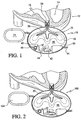
- Fig. 1 shows a fluid transfer device or pump according to the invention, in use as a ventricular assist device (VAD) 10.
- VAD ventricular assist device
- VAD 10 of Fig. 1 is shown in use on a heart 12 having a left ventricle 14 and a right ventricle 16.
- VAD 10 is shown in use as a right ventricular assist device (RVAD), shown fluidly connected to the right ventricle 16 of the heart.
- RVAD right ventricular assist device
- VAD 10 may be provided with a housing 14, which may be substantially rigid.
- Housing 14 may be made of a material selected for a compatibility with tissue.
- the fluid connection of RVAD 10 to the heart may be made with a connector 18 compatible with heart tissue, such connectors 18 being known.
- a pacemaker control 24 for an RVAD may be used for controlling the timing of the RVAD in conjunction with the beating of the heart, as will be described further below.
- An expansion chamber 30 having an expanded state 32 and an unexpanded state or mode 36 may be provided within housing 14. In expanded state or mode 32 the expansion chamber will be substantially filled with blood and in the unexpanded or resting state 36 the expansion chamber may be substantially empty.
- a compressor or pump 42 such as an electric vacuum pump, is provided for pressurizing a pressure tank 44 by pumping a fluid, such as a gas into pressure tank 44.
- a valve 46 which may be controlled by the pacemaker control 24 and associated control(s), such as an integrated chip 48 or other electronic controls, as will be readily understood, may serve to regulate the flow of the fluid located in the interior 48 of the housing for controlling the expansion and contraction of the expansion chamber 30.
- a power source 50 such as a battery contained within housing 14, or an external battery or pneumatic or vacuum supply, may be used to power compressor 42.
- an externally controlled and operated vacuum and vent source may be used to expand and contract the chamber 30.
- Battery 50 may be externally recharged via a body port connection 54.
- Expansion chamber 30 may have one or more lobe-shaped or finger-like extensions. Three(3) finger-like extensions are shown.
- One opening 58 of expansion chamber 30 may be fluidly connected with connector 18 and, thus, fluidly connected to the user's heart.
- compressor 42 draws in fluid, such as gas, contained in interior 48 of the housing, compresses the fluid, and forces the fluid into tank 44, as will be readily appreciated.
- fluid such as gas
- control 24 causes blood to be discharged from expansion chamber 30 through hole or fluid connection 58 synchronous with the discharging of the heart chamber.
- the blood is discharged by opening valve 46 fluidly connected to tank 44, thereby releasing pressurized gas from tank 44, refilling interior 48, thus raising the pressure therein, and causing expansion chamber 30 to return to its unexpanded state 36.
- the expansion chamber may be configured so that its natural state is unexpanded state 36, the elasticity of the material of expansion chamber assisting/causing the expansion chamber to return to its unexpanded state 36. In this manner, the expansion chamber returns to its unexpanded state should there by an unwarranted interruption in the operation of the VAD, such as in the case of a power failure.
- the timing of the valve may be controlled by a known sense/pace pacemaker.
- the rate may automatically adjust discharge valve firing as needed. This may be termed a "pulsatile" type device.
- the tank may be at atmospheric pressure so that there would not be a positive pressure within the user's body greater than atmospheric, in use.
- RVAD 10 may be used without an artificial valve in conjunction with the natural valves of the heart, and need only be connected in one place on the heart, as appropriate, with known connective material. Beating (pumping) in sequence with the normal rate of the heart as fired by the pacemaker that senses heart rate change varies the operation of the compressor and/or the valve accordingly.
- Fig. 2 illustrates a left ventricular assist device (LVAD) 100 controlled by a pacemaker 124, and other controls depending on the configuration of the like components.
- LVAD left ventricular assist device
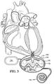
- Fig. 3 is schematic cross sectional view of a further fluid transfer device 130, such as a ventricular assist device, shown fluidly connected to a ventricle of a heart for assisting in pumping blood through the heart.
- a further fluid transfer device 130 such as a ventricular assist device
- Cardiac assist device 130 is similar to the embodiment of Figs. 1 and 2 , with the addition of a further cavity 132 within housing 131.
- Further cavity 132 may be used to divide-the interior of housing 131 into an inner cavity 133 and an outer cavity 135.
- wall 132 defining inner cavity 133 may include one or more curved regions 138, 142, and 144. Regions 138, 142, and 144 may be disclosed and configured for receiving expandable chamber or bladder 30 in its expanded conditions. For example, lobes or fingers or extensions 158, 162, and 164 may expand into the regions defined by respective ones of portions 138, 142, and 144.
- chamber 30 need not expand into contact with the inner wall of chamber 132.
- 132 may be configured so as to control expansion of chamber 30, as needed, in use.
- Fig. 4 shows chamber or bladder 30 in an unexpanded condition at atmospheric pressure with valve 58 in a closed position.
- FIG. 5 shows chamber 30 in what may be termed a fully expanded condition having fully expanded lobes 168, 172, and 174 corresponding to respective ones of unexpanded lobes 158, 162, and 164.
- valves 184 may be provided for controlling the accumulation and release of a fluid into and from pressure tank 44 into and from the inner cavity 133 for assisting in the expansion and contraction of chamber 30.
- pump 42 may force a fluid provided in interior 133 in between the exterior of chamber 30 and the lobed inner wall 132 for developing a pressure less than atmospheric pressure within cavity 133; i.e. for developing a vacuum therein and, thus, causing chamber 30 to expand and draw in blood from the portion of the heart to which the device 130 is attached, in use.
- valve 184 is open to allow release of fluid from pressure tank 44, to pressurize fluid exiting through valve 44 and fill and pressurizing cavity 133 so that, with the assistance of atmospheric pressure, the blood is forced out of expansion chamber 30 into the heart, in use.
- Pacemaker 124 and other appropriate controls will govern the expansion and contraction of chamber 30, as will be readily understood.
- Figs. 4 and 5 show the embodiment of Fig. 3 , in use.
- Fig. 6 is a schematic cross sectional view of another fluid transfer device 200 according to the invention similar to Fig. 3 shown fluidly connected to a ventricle of a heart for assisting in the pumping of blood through the heart.
- Cardiac assist device 200 shown in use as a ventricular assist device, is similar to the embodiments of Figs. 3-5 .
- Cardiac assist device 200 may include recharger 134 for recharging a battery for powering device 200, recharger 134 being at a location remote from housing 131.
- pacemaker 124 may be located at a location distant from housing 134, as shown in Fig. 6 , as will be readily appreciated.
- Fig. 7 is a schematic cross sectional view of another fluid transfer device 220 according to the invention shown fluidly connected to both a ventricle and the aorta of a heart for assisting in the pumping of blood through the heart.
- Fluid transfer device 220 may be used for patients requiring both a ventricular assist device 224 and an aortic assist device 234.
- Pacemaker 124 may be used to govern the operation, along with appropriate controls, as will be readily understood.
- recharger 134 shown in a remote location, may be used to recharge a battery used for powering both devices, or for recharging respective batteries found in each one of ventricular assist device 224 and aortic assist device 234.
- Fig. 8 is a schematic cross sectional view of another fluid transfer device 240 according to the invention shown fluidly connected to the aorta of a heart for assisting in the pumping of blood through the heart.
- Device 240 of Fig. 8 may be used as an aortic assist device 240, as shown.
- Pacemaker 124 may be used for controlling operation, and recharger 134 may be used for recharging an implanted battery housed within the casing of aortic assist device 240, as will be readily understood.
- Appropriate controls may be located within the housing of aortic assist device 240, outside the housing, and fully implanted, as patient requirements dictate, as in the other embodiments.
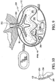
- Fig. 9 is a schematic cross sectional view of another fluid transfer device 250 according to the invention shown fluidly connected to a portion of a heart for assisting in the pumping of blood through the heart.
- Fluid transfer device 250 may be termed a ventricular assist device, as it is shown connected to a ventricle of a patient's heart, as in other embodiments described herein.
- Ventricular assist device 250 may include an opening or fluid connection 252 having no valve. Thanks to the configuration of expandable chamber or bladder 30 and the configuration of fluid connection 252, sufficient blood which had been drawn into the interior of chamber 30 during the expansion of chamber 30 will be exited or pushed out of the interior of chamber 30 under the influence of the pressurized fluid in the pressure tank and the pressure exerted by atmospheric pressure so that substantially no stagnant blood will remain within chamber 30. In other words, sufficiently little stagnant blood will remain in chamber 30 so as to lead to clotting. It is likewise contemplated that in a region 253, such as the illustrated narrowing region 253 of bladder 30, the bladder or expandable chamber 30 may be configured so that in its unexpanded condition, narrowed portion 253 completely closes and functions as a valve. In that manner, no additional valve need be used in the region of fluid connection 252.
- Fig. 10 is a partial cross sectional view of the fluid transfer device of Fig. 9 .
- the wall or inner housing defining inner cavity 133 may be provided with one or more throughholes or perforations 254 and 256.
- a plurality of perforations 254 and 256 may be used to ensure that chamber 30 is expanded evenly, and to reduce the likelihood that a portion of chamber 30 might block a single hole, in use.
- the negative pressure developed by the pump may be developed in an inner volume 258 for thus developing a negative pressure within the inner volume 262 defined within lobed wall 132 defining a lobed cavity and outside of lobed expandable chamber 30.
- a sensor may be provided for determining whether or not there is a fluid leak within cavity 262; i.e. a fluid leak which might correspond to fluid leaking out of expandable chamber 30, in use.
- sensor 264 may sense the presence of leaked blood.
- Sensor 264 may sense the presence of blood by the use of a photosensor detecting a change in light or color within cavity 262 in the presence of blood.
- Sensor 264 may also include a moisture sensor or hygrometer for detecting a change in moisture content or relative humidity corresponding to the presence of a leaked fluid.
- sensor 264 may include a chemical sensor detecting the presence of a chemical or change in chemical composition.
- Sensor 264 may likewise include an electrical sensor for detecting a change in electrical resistance, for example.
- an inner wall 268 may be treated or coated with a chemical for indicating the presence of a leak, such as by a change in chemical properties which may be detected by sensor 264.
- Fig. 11 is a schematic cross sectional view of another fluid transfer device according to the invention that requires no pacemaker and is shown fluidly connected to a portion of a heart for assisting in the pumping of blood through the heart.
- Device 270 of Fig. 11 may be used as a ventricular assist device, as shown. Device 270 may be particularly suited for compact or fully implanted situations. Device 270 may include a combined compressor and pressure tank or accumulator 280. Combination compressor and pressure tank 280 may include a pump or compressor 282 in one portion and a pressure tank 284 in another portion.
- Controls such as an electronic control, may be provided.
- a valve 294 may fluidly connect compressor 282 pressure tank 284, and inner cavity 295, for example.
- a perforated wall 132 may be provided so that the development of a vacuum in cavity 295 may serve to develop a respective vacuum in cavity 297 for expanding expandable chamber 30, along the lines described above.
- a sensor 296, such as a pressure sensor may be provided that is configured to substitute for the use of a pacemaker.
- Pressure sensor 296 may be configured to sense an increase in the blood pressure within a patient's heart, in use, so that thanks to control 274, the overall combination of elements will serve to function in concert with the pumping of the heart to assist in such pumping. Thanks to the use of an appropriate pressure sensor which detects changes in pressure transmitted through the fluid connection between the heart and pressure sensor 296, such fluid connection including the fluid (i.e.
- Fig. 12 illustrates another embodiment of a fluid transfer device, such as an artificial heart, shown with four valves for use in complete heart replacement.
- Fluid transfer device 300 may be used as an artificial heart 300, as shown.
- Artificial heart 300 may include a housing 310 including a first subhousing 312 and a second subhousing 314.
- First and second expandable lobed chambers 316 and 318 may be provided in respective housings 312 and 314.
- a first fluid connection 320 may be provided for fluidly connecting chamber 316 with the exterior of cavity 312.
- First fluid connection 320 may include respective right and left fluid connections 322 and 324, each having respective left and right fluid valves 326 and 328.
- lobed chamber 318 may include a fluid connection 340 including left and right fluid connections 342 and 344, each such fluid connections 342 and 344 having respective left and right valves 346 and 348.
- fluid flow would be in respective directions represented by arrows 380, 382, 386 and 388, governed by controls 370 which dictate the manner in which respective valves 324, 326, 346, and 348 are opened and closed.
- controls 370 which dictate the manner in which respective valves 324, 326, 346, and 348 are opened and closed.
- valves 326, 328, 346, and 348 may be actively controlled by control 370.
- One or more of the valves may be controlled by the expansion of chambers 316 and 318, depending on the intended use.
- one or more combined compressors and pressure tanks 390 may be used; or, the pump 390 may be used and associated valve 394 so that interior 395 of subhousing 312 may be used as the pressure tank, as described in connection with other embodiments. It will be appreciated that the various controls may be used as in the other embodiments.
- Any of the embodiments may be monitored from outside a patient's body, in use.
- Any of the embodiments may be provided with variable pumping rates and volumes, pulsatile pumping, and other fine-tuning of the pumping of blood, in use, in order to enhance the operation of any of the embodiments, and so that any of the embodiments may be used for children so that the rate may be varied as they grow in stature, and for adult patients, so that the heart pressure and volume and rate may be increased as the patient convalesces, as deemed necessary.
- any of the embodiments appropriate coatings may be provided on any of the interior and exterior of the expandable chambers and/or on the interior of the rigid housing or rigid lobed wall defining an outermost extent of the expansion chamber so as to eliminate platelet accumulation, reduced sheer, indicate fluid leaks, and enhance compatibility, and the like.
- any of the embodiments may be configured to minimize the surface area of the expandable chamber so as to minimize the surfaces on which platelets may accumulate, in the case where embodiments are used as cardiac assist devices or for pumping blood.
- Any of the embodiments may be configured to minimize the stagnant (i.e. unpumped) volume of the material being pumped.
- a pacemaker may be eliminated in respective embodiments, depending on the intended use.
- devices in accordance with the invention may be used to replace entire chambers of the heart with the use of artificial inlet and outlet valves, as required.
- the pump may be located outside the body and used to pump blood.
- the valve may be partially open during the compression stage.
- Additional control(s), such as a dedicated chip, may be provided.
- One or more of the pump, compressor, pressure tank, battery, battery charger, controls, and the like may be located inside the housing, outside the housing and inside the patient's body, and/or outside of the patient's body, depending on patient requirements, for example, and other considerations.
Description
- The invention relates to fluid transfer devices. More particularly, the invention relates to nondestructive fluid transfer devices. Even more particularly, the invention relates to fluid transfer devices particularly suited for use in medical applications, such as in the pumping of blood.
- Fluid transfer devices such as pumps are known. Artificial heart assistance devices, such as ventricular assist devices (VADs) that draw blood from one of the ventricles of the heart and push the blood through the aorta are known, for instance from
FR 1 538 644 - Known devices have proven unsatisfactory for pumping blood and other easily damaged fluids.
- Known cardiac assist devices have many drawbacks related to the particular requirements of pumping blood, useful life, and so forth.
- It is an object of the invention to overcome the drawbacks of known devices.
- A further object of the invention is to provide a fluid transfer device, such as a pump, usable for pumping fluids, such as liquids and gases.
- A further object of the invention is to provide a fluid transfer device, such as a pump, usable for pumping destructible fluids, such as blood.
- Another object of the invention is to provide a fluid transfer device which may be used internally or externally for assisting the heart.
- A further object of the invention is to provide a nonshearing fluid transfer device, such as a pump.
- A further object of the invention is to provide a fluid transfer device such as a pump, which may be used for pumping any destructible fluid, including viscous, semi-solid, and other fluids, including foodstuffs, such as salsa or chunky spaghetti sauce for which the user wants to maintain the integrity of the larger chunks of food, as well as condiments, or the dispensing of non-food product, such as soaps and shampoos, as the marketplace demands.
- Yet another object of the invention is to provide a fluid transfer device which stores products until such time as the product is to be dispensed, such as for the dispensing of food, and other products, whether or not such products are readily degraded.
- A still further object of the invention is to provide a fluid transfer device such as a pump, which inherently automatically continually cleans itself, in use.
- A further object of the invention is to provide a fluid transfer device configured for pumping blood that automatically cleans itself.
- A further object of the invention is to provide a medical pump which may be controlled by conventional pacemaker controls, in the case where the medical pump is used to assist the heart.
- A still further object of the invention is to provide a fluid transfer device which may be used as a cardiac assist device, such as an aortic assist device or ventricular assist device (VAD), with or without the addition of one or more artificial heart valves.
- Yet another object of the invention is to provide a fluid pump which may be used with an additional pump and requisite valving, power source, and controls to serve as an artificial heart.
- Yet another object of the invention is to provide a medical device for transferring or pumping blood that has no entrapment areas, dead zones, or quiescent points that may lead to clotting and/or shearing of platelets and/or red blood cells (RBCs), for example, as in known devices.
- A still further object of the invention is to provide a fluid transfer device, such as a pump, which avoids cross-fluid transfer or contamination.
- A still further object of the invention is to provide a pump which prevents the evacuation of pressurized gas into the fluid being pumped.
- Yet another object of the invention is to provide a pump which has a fail-safe mode selected to avoid destruction of the system in which the pump operates.
- Another object of the invention is to provide a cardiac assist device which does not hamper heart blood flow in the case where the cardiac assist device suffers a loss of power.
- Yet another object of the invention is to provide a cardiac assist device configured so that if a leak develops then a signal is sent to the user and/or the operation of the cardiac assist device is altered.
- Another object of the invention is to provide a cardiac assist device configured so that in the event the cardiac assist device operation is altered or stops pumping blood (such as in the case of a power failure), less clotting of blood occurs than in known devices.
- A further object of the invention is to provide a cardiac assist device configured so that sufficiently little clotting of a patient's blood occurs so as to enable the reduction or elimination of the patient's use of antiplatelet agents and/or anticoagulants than required by the use of known devices.
- Another object of the invention is to provide a blood pump, such as a cardiac assist device, or an artificial heart, which causes little or no degradation of constituents of the blood being pumped.
- Still another object of the invention is to provide a blood pumping device, such as a cardiac assist device, which substantially completely refreshes the volume of pumped blood and retains sufficiently little unpumped blood in its stopped or non-pumping state, so that there is substantially no accumulation of blood within the blood pump; i.e., blood which is not continually refreshed.
- A further object of the invention is to provide a blood pump configured for minimizing the surface area of the pumping mechanism in contact with the blood being pumped, so as to minimize the surface area on which platelet accumulation and clotting may occur.
- Another object of the invention is to provide a blood pump, such as a cardiac assist device, including a pumping element configured and selected so that a predetermined platelet accumulations occurs on a surface of the pumping device in contact with the blood being pumped, the predetermined accumulation being selected so as to prevent an undesirable excess accumulation of platelets which may lead to undesirable clotting of the blood being pumped.
- A further object of the invention is to provide a blood pump which minimizes the volume of stagnant blood remaining in the pumping element of the pump during a non-pumping stage of a pumping cycle; i.e. a device which minimizes an umpumped volume resident in the blood pumping element of the blood pump.
- Yet another object of the invention is to provide a cardiac assist device which requires no pacemaker.
- Another object of the invention is to provide a cardiac assist device including one or more sensors capable of detecting one or both of the influx and outflow of blood into a ventricle of a heart, and/or the increase and decrease of the fluid pressure exerted by the blood in the heart to which it is connected; the detection by such sensor(s) being used to operate the cardiac assist device without an auxiliary control, such as a pacemaker.
- The present disclosure describes a method of implanting a cardiac assist device, such as an aortic or ventricular assist device, completely within a patient's torso or chest and, indeed, without the splitting of the sternum.
- A further object of the invention is to provide a method of implanting a cardiac device, such as an artificial heart, completely within a patient's torso or chest.
- Another object of the invention is to provide a cardiac assist device including a pumping element, such as a bladder, which includes a coating or layer or sensor adjacent the bladder and configured and selected so as to detect a fluid leak.
- Another object of the invention is to minimize gas permeation into blood being pumped, as occurred in prior art gas-filled systems, the reduction of the likelihood of gas permeation being accomplished by, for example, the use of a negative pressure (e.g., the development of a vacuum) to draw in blood to be pumped, and the use of fluid at atmospheric pressure to pump out blood into the interior of the heart.
- Another object of the invention is to provide a blood pump, such as a cardiac assist device, which reduces infection, thanks to its being fully implantable.
- A further object of the invention is to provide a blood pump, such as a cardiac assist device, which may be configured for use in smaller patients, such as infants and preadolescents.
- Another object of the invention is to provide a blood pump, such as a cardiac assist device, which may have a variable pumping rate and volume, which variable pumping rate and volume may be adjusted from outside the patient's body, so that, as an adult patient recovers, or as a child grows, for example, the pumping rate and volume may be increased, thereby eliminating the need to implant a new, larger device, as had been the case in the prior art.
- Another object of the invention is to provide a blood pump, such as a cardiac assist device, having sufficiently low energy requirements that it may be operated by transformer coupled charging through the patient's skin.
- A further object of the invention is to provide a blood pump, such as a cardiac assist device, which requires no percutaneous transfer of fluid energy or electrical energy in order to operate.
- Yet another object of the invention is to provide a blood pump, such as a cardiac assist device, which includes a pulsatile pump, including a pulsatile pump with a variable pulsing rate.
- A further object of the invention is to provide a blood pump, such as a cardiac assist device, in which one or both of the pumped fluid volume and the pumped fluid pressure may be varied.
- Another object of the invention is to provide a blood pump, such as a cardiac assist device, which may be controlled by an implanted pacemaker inside or outside of the cardiac assist device housing and/or by pressure sensors configured for sensing blood pressure within a patient's heart, which pressure sensors may be provided inside or outside the housing of the cardiac assist device.
- Another object of the invention is to provide a blood pump, such as a cardiac assist device, which includes an atmospheric pressure sensor, so that the pressure exerted by the pump may be varied to be substantially the same as atmospheric pressure to account for variations in atmospheric pressure, such as when the patient moves to a higher altitude.
- Yet another object of the invention is to provide a blood pump, such as a cardiac assist device, which sufficiently minimizes stagnant blood contained within the pumping element of the device that no valve is required between the pumping element and the inside portion of the patient's heart to which the pumping device is fluidly connected.
- Yet another object of the invention is to provide a blood pump which may be fluidly connected to one or more of the interior regions of a patient's heart, including, for example, the right ventricle, the left ventricle, the aorta, and so forth.
- In summary, the invention is defined in
claim 1. - The expansion chamber may be made of an elastic material.
- The expansion chamber is configured so that it has a In summary, the invention is defined in
claim 1. normally unexpanded state; i.e. in its relaxed mode, it is in an unexpanded condition. - The power unit for expanding the expansion chamber may include a compressor.
- A pressure tank may be fluidly connected with the compressor.
- A valve or valves may be fluidly connected with one or more of the compressor, the pressure tank, and the expansion chamber for controlling the rate at which the expansion chamber expands and contracts, such as based on the blood flow requirements of a heart which is being assisted by the inventive device.
- A control may be provided for varying the pumping rate of the pump or compressor.
- The expansion chamber includes one or more lobes or fingers that draw in liquid and are filled with liquid as the expansion chamber expands, and which evacuate or expel liquid, such as blood, as the expansion chamber contracts or returns to its unexpanded state.
- The lobe(s) or finger(s) are configured for sufficiently evacuating the fluid being transferred or pumped so that the expansion chamber is automatically continually cleaned; e.g., the fluid in all areas or regions of the expansion chamber is continually replaced and removed with newly drawn in fluid.
- Relative terms such as left, right, first, second, up, and down are for convenience only and are not intended to be limiting.
-
-
Fig. 1 is a schematic cross sectional view of a fluid transfer device, such as a ventricular assist device, fluidly connected to the right ventricle of a heart for assisting in pumping blood through the heart; -
Fig. 2 is a schematic cross sectional view of fluid transfer device, such as a ventricular assist device, fluidly connected to the left ventricle of a heart for assisting in pumping blood through the heart; -
Fig. 3 is schematic cross sectional view of a further fluid transfer device, such as a ventricular assist device, shown fluidly connected to a ventricle of a heart for assisting in pumping blood through the heart; -
Figs. 4 and 5 show the embodiment ofFig. 3 , in use; -
Fig. 6 is a schematic cross sectional view of another fluid transfer device according to the invention similar toFig. 3 shown fluidly connected to a ventricle of a heart for assisting in the pumping of blood through the heart; -
Fig. 7 is a schematic cross sectional view of another fluid transfer device according to the invention shown fluidly connected to both a ventricle and the aorta of a heart for assisting in the pumping of blood through the heart; -
Fig. 8 is a schematic cross sectional view of another fluid transfer device according to the invention shown fluidly connected to the aorta of a heart for assisting in the pumping of blood through the heart; -
Fig. 9 is a schematic cross sectional view of another fluid transfer device according to the invention shown fluidly connected to a portion of a heart for assisting in the pumping of blood through the heart; -
Fig. 10 is a partial cross sectional view of the fluid transfer device ofFig. 9 ; -
Fig. 11 is a schematic cross sectional view of another fluid transfer device according to the invention that requires no pacemaker and is shown fluidly connected to a portion of a heart for assisting in the pumping of blood through the heart; and -
Fig. 12 illustrates another embodiment of a fluid transfer device, such as an artificial heart, shown with four valves for use in complete heart replacement. -
Fig. 1 shows a fluid transfer device or pump according to the invention, in use as a ventricular assist device (VAD) 10. -
VAD 10 ofFig. 1 is shown in use on aheart 12 having aleft ventricle 14 and aright ventricle 16.VAD 10 is shown in use as a right ventricular assist device (RVAD), shown fluidly connected to theright ventricle 16 of the heart. -
VAD 10 may be provided with ahousing 14, which may be substantially rigid.Housing 14 may be made of a material selected for a compatibility with tissue. - The fluid connection of RVAD 10 to the heart may be made with a connector 18 compatible with heart tissue, such connectors 18 being known.
- A
pacemaker control 24 for an RVAD may be used for controlling the timing of the RVAD in conjunction with the beating of the heart, as will be described further below. - An
expansion chamber 30 having an expandedstate 32 and an unexpanded state ormode 36 may be provided withinhousing 14. In expanded state ormode 32 the expansion chamber will be substantially filled with blood and in the unexpanded or restingstate 36 the expansion chamber may be substantially empty. - A compressor or pump 42, such as an electric vacuum pump, is provided for pressurizing a
pressure tank 44 by pumping a fluid, such as a gas intopressure tank 44. Avalve 46, which may be controlled by thepacemaker control 24 and associated control(s), such as anintegrated chip 48 or other electronic controls, as will be readily understood, may serve to regulate the flow of the fluid located in theinterior 48 of the housing for controlling the expansion and contraction of theexpansion chamber 30. - A
power source 50, such as a battery contained withinhousing 14, or an external battery or pneumatic or vacuum supply, may be used topower compressor 42. Alternatively, an externally controlled and operated vacuum and vent source may be used to expand and contract thechamber 30. -
Battery 50 may be externally recharged via abody port connection 54. -
Expansion chamber 30 may have one or more lobe-shaped or finger-like extensions. Three(3) finger-like extensions are shown. Oneopening 58 ofexpansion chamber 30 may be fluidly connected with connector 18 and, thus, fluidly connected to the user's heart. - In
use compressor 42 draws in fluid, such as gas, contained ininterior 48 of the housing, compresses the fluid, and forces the fluid intotank 44, as will be readily appreciated. In this manner, as the amount of gas ininterior 68 is reduced, the pressure on the exterior ofexpansion chamber 30 is reduced, andexpansion chamber 30 expands to its expandedcondition 32, thereby drawing blood intoexpansion chamber 30. At the appropriate time as dictated by the heart beat,control 24 causes blood to be discharged fromexpansion chamber 30 through hole orfluid connection 58 synchronous with the discharging of the heart chamber. The blood is discharged by openingvalve 46 fluidly connected totank 44, thereby releasing pressurized gas fromtank 44, refillinginterior 48, thus raising the pressure therein, and causingexpansion chamber 30 to return to itsunexpanded state 36. The expansion chamber may be configured so that its natural state isunexpanded state 36, the elasticity of the material of expansion chamber assisting/causing the expansion chamber to return to itsunexpanded state 36. In this manner, the expansion chamber returns to its unexpanded state should there by an unwarranted interruption in the operation of the VAD, such as in the case of a power failure. - Quite simply, the timing of the valve may be controlled by a known sense/pace pacemaker. The rate may automatically adjust discharge valve firing as needed. This may be termed a "pulsatile" type device.
- The tank may be at atmospheric pressure so that there would not be a positive pressure within the user's body greater than atmospheric, in use.
- As shown,
RVAD 10 may be used without an artificial valve in conjunction with the natural valves of the heart, and need only be connected in one place on the heart, as appropriate, with known connective material. Beating (pumping) in sequence with the normal rate of the heart as fired by the pacemaker that senses heart rate change varies the operation of the compressor and/or the valve accordingly. -
Fig. 2 illustrates a left ventricular assist device (LVAD) 100 controlled by apacemaker 124, and other controls depending on the configuration of the like components. -
Fig. 3 is schematic cross sectional view of a furtherfluid transfer device 130, such as a ventricular assist device, shown fluidly connected to a ventricle of a heart for assisting in pumping blood through the heart. -
Cardiac assist device 130 is similar to the embodiment ofFigs. 1 and 2 , with the addition of afurther cavity 132 withinhousing 131.Further cavity 132 may be used to divide-the interior ofhousing 131 into aninner cavity 133 and anouter cavity 135. As shown and described in greater detail with reference toFigs. 4 and 5 ,wall 132 defininginner cavity 133 may include one or morecurved regions Regions bladder 30 in its expanded conditions. For example, lobes or fingers orextensions portions - In use,
chamber 30 need not expand into contact with the inner wall ofchamber 132. However, 132 may be configured so as to control expansion ofchamber 30, as needed, in use. -
Fig. 4 shows chamber orbladder 30 in an unexpanded condition at atmospheric pressure withvalve 58 in a closed position. -
Fig. 5 showschamber 30 in what may be termed a fully expanded condition having fully expandedlobes unexpanded lobes - Appropriate controls, such as a pacemaker, dedicated control chip, and the like may be provided as will be readily understood. For example, one or
more valves 184 may be provided for controlling the accumulation and release of a fluid into and frompressure tank 44 into and from theinner cavity 133 for assisting in the expansion and contraction ofchamber 30. - Quite simply, as in the previous embodiment, pump 42 may force a fluid provided in
interior 133 in between the exterior ofchamber 30 and the lobedinner wall 132 for developing a pressure less than atmospheric pressure withincavity 133; i.e. for developing a vacuum therein and, thus, causingchamber 30 to expand and draw in blood from the portion of the heart to which thedevice 130 is attached, in use. Then, when the drawn in blood is to be sent back into the heart for assisting in the pumping of blood in a patient, for example,valve 184 is open to allow release of fluid frompressure tank 44, to pressurize fluid exiting throughvalve 44 and fill and pressurizingcavity 133 so that, with the assistance of atmospheric pressure, the blood is forced out ofexpansion chamber 30 into the heart, in use.Pacemaker 124 and other appropriate controls will govern the expansion and contraction ofchamber 30, as will be readily understood. -
Figs. 4 and 5 show the embodiment ofFig. 3 , in use. -
Fig. 6 is a schematic cross sectional view of anotherfluid transfer device 200 according to the invention similar toFig. 3 shown fluidly connected to a ventricle of a heart for assisting in the pumping of blood through the heart. -
Cardiac assist device 200, shown in use as a ventricular assist device, is similar to the embodiments ofFigs. 3-5 .Cardiac assist device 200 may includerecharger 134 for recharging a battery for poweringdevice 200,recharger 134 being at a location remote fromhousing 131. - Likewise,
pacemaker 124 may be located at a location distant fromhousing 134, as shown inFig. 6 , as will be readily appreciated. -
Fig. 7 is a schematic cross sectional view of anotherfluid transfer device 220 according to the invention shown fluidly connected to both a ventricle and the aorta of a heart for assisting in the pumping of blood through the heart. -
Fluid transfer device 220 may be used for patients requiring both aventricular assist device 224 and anaortic assist device 234. -
Pacemaker 124 may be used to govern the operation, along with appropriate controls, as will be readily understood. Likewise,recharger 134, shown in a remote location, may be used to recharge a battery used for powering both devices, or for recharging respective batteries found in each one ofventricular assist device 224 andaortic assist device 234. -
Fig. 8 is a schematic cross sectional view of anotherfluid transfer device 240 according to the invention shown fluidly connected to the aorta of a heart for assisting in the pumping of blood through the heart. -
Device 240 ofFig. 8 may be used as anaortic assist device 240, as shown.Pacemaker 124 may be used for controlling operation, andrecharger 134 may be used for recharging an implanted battery housed within the casing ofaortic assist device 240, as will be readily understood. Appropriate controls may be located within the housing ofaortic assist device 240, outside the housing, and fully implanted, as patient requirements dictate, as in the other embodiments. -
Fig. 9 is a schematic cross sectional view of anotherfluid transfer device 250 according to the invention shown fluidly connected to a portion of a heart for assisting in the pumping of blood through the heart. -
Fluid transfer device 250 may be termed a ventricular assist device, as it is shown connected to a ventricle of a patient's heart, as in other embodiments described herein. - Ventricular assist
device 250 may include an opening orfluid connection 252 having no valve. Thanks to the configuration of expandable chamber orbladder 30 and the configuration offluid connection 252, sufficient blood which had been drawn into the interior ofchamber 30 during the expansion ofchamber 30 will be exited or pushed out of the interior ofchamber 30 under the influence of the pressurized fluid in the pressure tank and the pressure exerted by atmospheric pressure so that substantially no stagnant blood will remain withinchamber 30. In other words, sufficiently little stagnant blood will remain inchamber 30 so as to lead to clotting. It is likewise contemplated that in aregion 253, such as the illustratednarrowing region 253 ofbladder 30, the bladder orexpandable chamber 30 may be configured so that in its unexpanded condition, narrowedportion 253 completely closes and functions as a valve. In that manner, no additional valve need be used in the region offluid connection 252. -
Fig. 10 is a partial cross sectional view of the fluid transfer device ofFig. 9 . - The wall or inner housing defining
inner cavity 133 may be provided with one or more throughholes orperforations perforations chamber 30 is expanded evenly, and to reduce the likelihood that a portion ofchamber 30 might block a single hole, in use. In this manner, the negative pressure developed by the pump may be developed in aninner volume 258 for thus developing a negative pressure within theinner volume 262 defined withinlobed wall 132 defining a lobed cavity and outside of lobedexpandable chamber 30. - As in other preferred embodiments of the invention, a sensor may be provided for determining whether or not there is a fluid leak within
cavity 262; i.e. a fluid leak which might correspond to fluid leaking out ofexpandable chamber 30, in use. In the case ofventricular assist device 250,sensor 264, may sense the presence of leaked blood.Sensor 264 may sense the presence of blood by the use of a photosensor detecting a change in light or color withincavity 262 in the presence of blood.Sensor 264 may also include a moisture sensor or hygrometer for detecting a change in moisture content or relative humidity corresponding to the presence of a leaked fluid. Still further,sensor 264 may include a chemical sensor detecting the presence of a chemical or change in chemical composition.Sensor 264 may likewise include an electrical sensor for detecting a change in electrical resistance, for example. These are merely examples and are not intended to be limiting. - In this manner, an
inner wall 268 may be treated or coated with a chemical for indicating the presence of a leak, such as by a change in chemical properties which may be detected bysensor 264. -
Fig. 11 is a schematic cross sectional view of another fluid transfer device according to the invention that requires no pacemaker and is shown fluidly connected to a portion of a heart for assisting in the pumping of blood through the heart. -
Device 270 ofFig. 11 may be used as a ventricular assist device, as shown.Device 270 may be particularly suited for compact or fully implanted situations.Device 270 may include a combined compressor and pressure tank oraccumulator 280. Combination compressor andpressure tank 280 may include a pump orcompressor 282 in one portion and apressure tank 284 in another portion. - Controls, such as an electronic control, may be provided.
- A
valve 294 may fluidly connectcompressor 282pressure tank 284, andinner cavity 295, for example. - A
perforated wall 132, as shown inFigs. 10 , may be provided so that the development of a vacuum incavity 295 may serve to develop a respective vacuum incavity 297 for expandingexpandable chamber 30, along the lines described above. - To further reduce size requirements, a
sensor 296, such as a pressure sensor, may be provided that is configured to substitute for the use of a pacemaker.Pressure sensor 296 may be configured to sense an increase in the blood pressure within a patient's heart, in use, so that thanks tocontrol 274, the overall combination of elements will serve to function in concert with the pumping of the heart to assist in such pumping. Thanks to the use of an appropriate pressure sensor which detects changes in pressure transmitted through the fluid connection between the heart andpressure sensor 296, such fluid connection including the fluid (i.e. the blood) withinchamber 30 and the fluid withincavity 297, it can be readily determined at which points in time thecontrol 274 should cause the compressor to evacuatecavity 295 and, hence, lower the pressure below atmospheric pressure, for drawing blood intochamber 30 by the expansion ofchamber 30, for example. Such pressure sensors and timing would be readily understood. -
Fig. 12 illustrates another embodiment of a fluid transfer device, such as an artificial heart, shown with four valves for use in complete heart replacement. -
Fluid transfer device 300 may be used as anartificial heart 300, as shown.Artificial heart 300 may include ahousing 310 including afirst subhousing 312 and asecond subhousing 314. First and second expandablelobed chambers respective housings - A
first fluid connection 320 may be provided for fluidly connectingchamber 316 with the exterior ofcavity 312.First fluid connection 320 may include respective right and leftfluid connections fluid valves - In a similar manner,
lobed chamber 318 may include afluid connection 340 including left andright fluid connections such fluid connections right valves - In use, fluid flow would be in respective directions represented by
arrows controls 370 which dictate the manner in whichrespective valves artificial heart 300 is attached to a patient's veins and arteries (e.g., at which ones of fluid connections 322,324,344, and 344) the artificial heart recipient's veins and arteries are being attached, one or more ofvalves control 370. One or more of the valves may be controlled by the expansion ofchambers - To enhance compactness, one or more combined compressors and
pressure tanks 390 may be used; or, thepump 390 may be used and associatedvalve 394 so thatinterior 395 ofsubhousing 312 may be used as the pressure tank, as described in connection with other embodiments. It will be appreciated that the various controls may be used as in the other embodiments. - Any of the embodiments may be monitored from outside a patient's body, in use.
- Any of the embodiments may be provided with variable pumping rates and volumes, pulsatile pumping, and other fine-tuning of the pumping of blood, in use, in order to enhance the operation of any of the embodiments, and so that any of the embodiments may be used for children so that the rate may be varied as they grow in stature, and for adult patients, so that the heart pressure and volume and rate may be increased as the patient convalesces, as deemed necessary.
- It is further contemplated that any of the embodiments appropriate coatings may be provided on any of the interior and exterior of the expandable chambers and/or on the interior of the rigid housing or rigid lobed wall defining an outermost extent of the expansion chamber so as to eliminate platelet accumulation, reduced sheer, indicate fluid leaks, and enhance compatibility, and the like.
- Any of the embodiments may be configured to minimize the surface area of the expandable chamber so as to minimize the surfaces on which platelets may accumulate, in the case where embodiments are used as cardiac assist devices or for pumping blood.
- Any of the embodiments may be configured to minimize the stagnant (i.e. unpumped) volume of the material being pumped.
- A pacemaker may be eliminated in respective embodiments, depending on the intended use.
- In any of the embodiments by the use of atmospheric pressure to discharge the fluid there is a reduced likelihood that gas will permeate the fluid being pumped, as has been the case in prior art gas-filled systems.
- It will be appreciated that devices in accordance with the invention may be used to replace entire chambers of the heart with the use of artificial inlet and outlet valves, as required.
- It is further contemplated that two(2) of these fluid transfer devices or pumps according to the invention, along with artificial heart valves, as required may be used to completely replace a patient's heart.
- The pump may be located outside the body and used to pump blood.
- In the case of children or certain conditions, the valve may be partially open during the compression stage.
- Additional control(s), such as a dedicated chip, may be provided.
- One or more of the pump, compressor, pressure tank, battery, battery charger, controls, and the like may be located inside the housing, outside the housing and inside the patient's body, and/or outside of the patient's body, depending on patient requirements, for example, and other considerations.
- While this invention has been described as having a preferred design, it is understood that it is capable of further modifications, and uses and/or adaptations of the invention and including such departures from the present disclosure as come within the known or customary practice in the art to which the invention pertains, and as may be applied to the central features hereinbefore set forth, and as fall within the scope of the invention.
Claims (18)
- A fluid transfer device (10), comprising:a) a housing (14) having a cavity therein;b) an expandable lobed chamber (30) provided in the cavity;c) a fluid connection (58) provided for fluidly connecting an interior of the expandable lobed chamber with the exterior of the housing;d) the housing (14) being configured and sufficiently strong to withstand a negative pressure between an exterior of the lobed chamber and within the cavity sufficiently great to cause the lobed chamber to expand into an expanded condition and draw a fluid through the fluid connection from the exterior of the housing into the interior of the lobed chamber when a negative pressure is established in the cavity;e) the lobed chamber (30) being configured so that the lobed chamber is in a substantially empty unexpanded condition when the cavity and, hence, the lobed chamber is at atmospheric pressure;
characterized in thatf) a pump (42) is provided in the housing to provide the negative pressure; andg) a battery (50) is provided, the battery being operatively connected to the pump - The fluid transfer device as in claim 1, wherein:a) the expandable lobed chamber (30) includes at least two lobes.
- The fluid transfer device as in claim 1, wherein:a) the expandable lobed chamber (30) includes at least three lobes.
- The fluid transfer device as in claim 1, wherein:a) the housing (14) is configured for being implanted in a patient for use as a ventricular assist device;b) the fluid connection (58) is configured for being fluidly connected to the interior of a ventricle of the patient's heart.
- The fluid transfer device as in claim 4, wherein:a) in the expanded condition and the unexpanded condition blood is sufficiently drawn into and discharged, respectively, from the lobed chamber (30) in use, so that insufficient platelet accumulation occurs to cause clotting of blood In the lobed chamber, in use.
- The fluid transfer device as in claim 5, wherein:a) the unexpanded condition the lobed chamber (30) is sized and configured so that there is substantially no stagnant fluid volume in the lobed chamber in the unexpanded condition, in use.
- The fluid transfer device as in claim 1, wherein:a) the battery (50) is rechargeable by a battery charger located externally of a patient's body, in use.
- The fluid transfer device as in claim 1, wherein:a) a control Is provided and operatively associated with the pump (42); andb) the control is configured for controlling at least one of the rate and volume, hence, the expansion and contraction of the chamber Into its respective expanded and unexpanded conditions.
- The fluid transfer device as in claim 1, wherein:a) the housing (14) is configured for being fully Implanted within a torso of a patient, in use.
- The fluid transfer device as in claim 1, wherein:a) a valve is provided in the fluid connection for opening and closing the fluid connection between the exterior of the housing (14) and the interior of the chamber (30), in use.
- The fluid transfer device as in claim 10, wherein:a) the fluid connection (58) is configured for being fluidly connected to the aorta of a patient's heart, in use.
- The fluid transfer device as in claim 10, wherein:a) the fluid connection (58) is configured for being connected to a ventricle of a patient's heart, in use; andb) a further housing (131) having a further cavity (132) is provided;c) a further expandable lobed chamber (316) is provided in the further cavity of the further housing;d) a further fluid connection is provided for fluidly connecting the exterior of the further housing with the interior of the further expandable lobed chamber;e) the further fluid connection Is configured for heing fluidly connected to the aorta of the patient's heart, in use;f) the further housing (314) being configured and sufficiently strong to withstand a negative pressure between an exterior of the further lobed chamber (318) and within the further cavity sufficiently great to cause the further lobed chamber (318) to expand into an expanded condition and draw a fluid through the fluid connection from the exterior of the further housing into the interior of the further lobed chamber when a negative pressure is established in the further cavity; andg) the further lobed chamber (318) being configured so that the further lobed chamber is in a substantially empty unexpanded condition when the further cavity and, hence, the further lobed chamber is at atmospheric pressure.
- The fluid transfer device as in claim 1, wherein:a) the cavity includes a first and a second cavity;b) the expandable lobed chamber includes a first (30) and second lobed chamber (132),c) the fluid connection includes first (320) and second (34) fluid connections;d) the first fluid connection includes left (322) and right (324) fluid connections;e) the second fluid connection includes left (342) and right (344) fluid connections;f) a valve (326, 328, 346, 348) is provided in each one of the respective left and right fluid connections of the first fluid connection and in each one of the respective left and right fluid connections of the second fluid connection;g) respective ones of the left and right fluid connections are connectable to respective veins and arteries of a patient, when implanted in a patient, in use;h) the pump is provided to establish the negative pressure sufficiently great to cause the first and second lobed chambers to expand;i) a control is provided and operatively associated with respective ones of the pump and the valves to cause the fluid transfer device to function as an artificial heart.
- The fluid transfer device as in claim 1, wherein:a) the housing (14) is fully implantable in a patient.
- The fluid transfer device as in claim 14, wherein:a) the battery is provided in the housing for operating the pump.
- The fluid transfer device as in claim 14, wherein:a) the fluid connection (58) is configured for being connected to a portion of a patient's heart; andb) a pressure sensor is operatively associated with the fluid connection and configured for sensing the fluid pressure within a patient's heart, so that the device can be operated and function as a cardiac assist device without the use of a pacemaker.
- The fluid transfer device as in claim 1, wherein:a) a pressure sensor is operatively associated with the cavity in the housing (14) and is configured for sensing the fluid pressure within the cavity for detecting fluid leaks into the cavity.
- The fluid transfer device as in claim 1, wherein:a) a sensor is operatively associated with the cavity in the housing (14) and is configured for sensing a fluid leak within the cavity, the sensor including one of a photosensor, a chemical sensor, an electrical sensor, and a moisture sensor.
Applications Claiming Priority (2)
| Application Number | Priority Date | Filing Date | Title |
|---|---|---|---|
| US53468504P | 2004-01-08 | 2004-01-08 | |
| PCT/US2005/000477 WO2005070477A1 (en) | 2004-01-08 | 2005-01-10 | Nondestructive fluid transfer device |
Publications (3)
| Publication Number | Publication Date |
|---|---|
| EP1715902A1 EP1715902A1 (en) | 2006-11-02 |
| EP1715902A4 EP1715902A4 (en) | 2011-07-06 |
| EP1715902B1 true EP1715902B1 (en) | 2016-05-25 |
Family
ID=34806882
Family Applications (1)
| Application Number | Title | Priority Date | Filing Date |
|---|---|---|---|
| EP05705240.9A Not-in-force EP1715902B1 (en) | 2004-01-08 | 2005-01-10 | Nondestructive fluid transfer device |
Country Status (10)
| Country | Link |
|---|---|
| US (2) | US7691046B2 (en) |
| EP (1) | EP1715902B1 (en) |
| CY (1) | CY1117924T1 (en) |
| DK (1) | DK1715902T3 (en) |
| ES (1) | ES2589579T3 (en) |
| HU (1) | HUE029978T2 (en) |
| LT (1) | LT1715902T (en) |
| PL (1) | PL1715902T3 (en) |
| PT (1) | PT1715902T (en) |
| WO (1) | WO2005070477A1 (en) |
Families Citing this family (30)
| Publication number | Priority date | Publication date | Assignee | Title |
|---|---|---|---|---|
| AU2002952691A0 (en) | 2002-11-15 | 2002-11-28 | Sunshine Heart Company Pty Ltd | Heart assist device utilising aortic deformation |
| JP5196786B2 (en) | 2003-10-31 | 2013-05-15 | サンシャイン・ハート・カンパニー・ピーティーワイ・リミテッド | Synchronous control system |
| LT1715902T (en) | 2004-01-08 | 2016-11-10 | Sullivan, Paul Joseph | Nondestructive fluid transfer device |
| ATE413200T1 (en) * | 2005-04-25 | 2008-11-15 | Hoffmann La Roche | INFUSION DEVICE WITH WATERPROOF CASE |
| US20090087328A1 (en) * | 2005-11-28 | 2009-04-02 | Faulkner Donald G | Pulse generating device |
| WO2008127703A2 (en) * | 2007-04-11 | 2008-10-23 | Transonic Systems, Inc | System and method for diverting flow to facilitate measurement of system parameters |
| US20110071337A1 (en) * | 2008-03-26 | 2011-03-24 | Cardio Assist Ltd. | Heart assist device |
| US8562507B2 (en) | 2009-02-27 | 2013-10-22 | Thoratec Corporation | Prevention of aortic valve fusion |
| CN102872486A (en) * | 2009-10-23 | 2013-01-16 | 杨碧波 | Cardiac impulse assist system |
| CN102107030B (en) * | 2009-12-28 | 2013-07-17 | 杨碧波 | Cardiac impulse assist device, cardiac impulse assist system and method for treating cardiac failure |
| CN102939117B (en) | 2010-04-02 | 2015-12-02 | 阳光心脏有限公司 | Combination heart assist system, method and apparatus |
| JP5818897B2 (en) | 2010-09-24 | 2015-11-18 | ソーラテック コーポレイション | Generation of artificial beats |
| WO2012112378A2 (en) * | 2011-02-18 | 2012-08-23 | Vascor Inc. | Blood flow assist systems |
| US8827889B2 (en) | 2012-05-21 | 2014-09-09 | University Of Washington Through Its Center For Commercialization | Method and system for powering implantable devices |
| US11621583B2 (en) | 2012-05-21 | 2023-04-04 | University Of Washington | Distributed control adaptive wireless power transfer system |
| AU2014225925A1 (en) * | 2013-03-05 | 2015-09-03 | Sunshine Heart Company Pty, Ltd. | Methods, systems, and devices relating to a fail-safe pump for a medical device |
| US9919088B2 (en) * | 2013-03-14 | 2018-03-20 | Yale University | Implantable heart pump controller |
| US10293082B2 (en) | 2014-07-23 | 2019-05-21 | Clemson University Research Foundation | Decellularization method and system and decellularized tissue formed thereby |
| US11034928B2 (en) | 2014-07-23 | 2021-06-15 | Clemson University Research Foundation | Modular bioreactor, compliance chamber for a bioreactor, and cell seeding apparatus |
| US10022225B2 (en) | 2014-07-23 | 2018-07-17 | Clemson University Research Foundation | Self-adjusting tissue holder |
| CN107223062B (en) | 2014-10-01 | 2019-12-17 | 心脏器械股份有限公司 | Standby controller system with updates |
| FR3026955B1 (en) * | 2014-10-10 | 2020-12-04 | Amesys | DEVICE FOR MANAGING THE FUNCTIONING OF A HEART PROSTHESIS |
| EP3487548B1 (en) | 2016-07-19 | 2021-03-17 | Heartware, Inc. | Ventricular assist devices and integrated sensors thereof |
| EP3600477B1 (en) | 2017-03-29 | 2022-10-26 | Tc1 Llc | Communication architecture for heart treatment systems |
| WO2018183565A1 (en) | 2017-03-29 | 2018-10-04 | Harjes Daniel I | Adjusting protocol based on irregular heart rhythm |
| EP3600478A1 (en) | 2017-03-29 | 2020-02-05 | Tc1 Llc | Pressure sensing ventricular assist devices and methods of use |
| WO2019178519A1 (en) | 2018-03-15 | 2019-09-19 | Tc1 Llc | Methods and systems for preventing right heart failure |
| US11167123B2 (en) | 2018-03-19 | 2021-11-09 | Tc1 Llc | Coordinated ventricular assist and cardiac rhythm management devices and methods |
| US11241570B2 (en) | 2018-07-17 | 2022-02-08 | Tc1 Llc | Systems and methods for inertial sensing for VAD diagnostics and closed loop control |
| IT202000015208A1 (en) * | 2020-06-24 | 2021-12-24 | Scuola Superiore Di Studi Univ E Di Perfezionamento Santanna | ARTIFICIAL CARDIAC MUSCLE |
Family Cites Families (30)
| Publication number | Priority date | Publication date | Assignee | Title |
|---|---|---|---|---|
| FR1538644A (en) * | 1967-07-28 | 1968-09-06 | Rhone Poulenc Sa | Heart prosthesis |
| US3608088A (en) | 1969-04-17 | 1971-09-28 | Univ Minnesota | Implantable blood pump |
| US4034742A (en) | 1973-01-31 | 1977-07-12 | Thoma Dipl Ing Dr Techn Herwig | Apparatus for mechanically assisting circulation of the blood in the human body |
| US3831203A (en) | 1973-09-28 | 1974-08-27 | Atomic Energy Commission | Implantable blood pumping system |
| JPS5242000B2 (en) * | 1973-10-01 | 1977-10-21 | ||
| AT344309B (en) | 1975-11-27 | 1978-07-10 | Felix Dr Med Unger | ARTIFICIAL CHAMBER OF HEART |
| US4250872A (en) | 1978-05-25 | 1981-02-17 | Yehuda Tamari | Blood pulsating and/or pumping device |
| US4222127A (en) * | 1978-06-02 | 1980-09-16 | Donachy And Pierce | Blood pump and method of pumping blood |
| US4573997A (en) | 1984-03-19 | 1986-03-04 | Research Corporation | Right ventricular assist device |
| US4690134A (en) | 1985-07-01 | 1987-09-01 | Snyders Robert V | Ventricular assist device |
| US4925443A (en) * | 1987-02-27 | 1990-05-15 | Heilman Marlin S | Biocompatible ventricular assist and arrhythmia control device |
| AU2134988A (en) * | 1987-07-23 | 1989-03-01 | Rosaria Bongiorno | Pneumatic device for withdrawing/dispensing fluids |
| US4938766A (en) | 1987-08-28 | 1990-07-03 | Jarvik Robert K | Prosthetic compliance devices |
| US4902291A (en) | 1989-01-31 | 1990-02-20 | University Of Utah Research Foundation | Collapsible artificial ventricle and pumping shell |
| US5089016A (en) | 1989-06-15 | 1992-02-18 | Abiomed Cardiovascular, Inc. | Blood pump |
| US5192314A (en) | 1991-12-12 | 1993-03-09 | Daskalakis Michael K | Synthetic intraventricular implants and method of inserting |
| US5282849A (en) | 1991-12-19 | 1994-02-01 | University Of Utah Research Foundation | Ventricle assist device with volume displacement chamber |
| AU3905093A (en) | 1992-04-17 | 1993-11-18 | Yoshiharu Kiyota | Intracorporeal heart assisting device |
| AU1675995A (en) | 1994-01-10 | 1995-08-01 | Cardassist Incorporated | Ventricular assist device |
| US5707336A (en) | 1995-01-09 | 1998-01-13 | Cardassist Incorporated | Ventricular assist device |
| IT1275135B (en) | 1995-02-06 | 1997-07-30 | Dideco Spa | PULSATILE PUMPING EQUIPMENT FOR LIQUIDS, IN PARTICULAR BLOOD. |
| US5899637A (en) * | 1996-12-11 | 1999-05-04 | American Oilfield Divers, Inc. | Offshore production and storage facility and method of installing the same |
| US5899937A (en) | 1997-03-05 | 1999-05-04 | Cryolife, Inc. | Pulsatile flow system for developing heart valves |
| UA56262C2 (en) * | 1997-10-09 | 2003-05-15 | Орквіс Медікел Корпорейшн | Extracardiac pumping system for supplementing blood circulation |
| IL142991A0 (en) | 1998-11-04 | 2002-04-21 | Cardio Tech Inc | Ventricular assist device with pre-formed inflation bladder |
| AUPR669001A0 (en) * | 2001-07-30 | 2001-08-23 | Sunshine Heart Company Pty Ltd | A fluid pressure generating means |
| US6579223B2 (en) | 2001-08-13 | 2003-06-17 | Arthur Palmer | Blood pump |
| US20030144574A1 (en) * | 2001-12-19 | 2003-07-31 | Heilman Marlin S. | Method and apparatus for providing limited back-flow in a blood pump during a non-pumping state |
| AR036548A1 (en) | 2002-09-18 | 2004-09-15 | Domingo Santo Liotta | BODY IMPLANT DEVICE FOR BLOOD CIRCULATORY ASSISTANCE AND VENTRICULAR CARDIACA |
| LT1715902T (en) * | 2004-01-08 | 2016-11-10 | Sullivan, Paul Joseph | Nondestructive fluid transfer device |
-
2005
- 2005-01-10 LT LTEP05705240.9T patent/LT1715902T/en unknown
- 2005-01-10 PL PL05705240T patent/PL1715902T3/en unknown
- 2005-01-10 HU HUE05705240A patent/HUE029978T2/en unknown
- 2005-01-10 PT PT57052409T patent/PT1715902T/en unknown
- 2005-01-10 DK DK05705240.9T patent/DK1715902T3/en active
- 2005-01-10 ES ES05705240.9T patent/ES2589579T3/en active Active
- 2005-01-10 WO PCT/US2005/000477 patent/WO2005070477A1/en active Application Filing
- 2005-01-10 EP EP05705240.9A patent/EP1715902B1/en not_active Not-in-force
-
2006
- 2006-07-10 US US11/482,791 patent/US7691046B2/en active Active - Reinstated
-
2010
- 2010-04-05 US US12/754,329 patent/US8246530B2/en active Active - Reinstated
-
2016
- 2016-08-24 CY CY20161100835T patent/CY1117924T1/en unknown
Also Published As
| Publication number | Publication date |
|---|---|
| DK1715902T3 (en) | 2016-09-05 |
| CY1117924T1 (en) | 2017-05-17 |
| LT1715902T (en) | 2016-11-10 |
| US20100191036A1 (en) | 2010-07-29 |
| EP1715902A4 (en) | 2011-07-06 |
| PT1715902T (en) | 2016-08-30 |
| US7691046B2 (en) | 2010-04-06 |
| WO2005070477A1 (en) | 2005-08-04 |
| US20060252977A1 (en) | 2006-11-09 |
| US8246530B2 (en) | 2012-08-21 |
| HUE029978T2 (en) | 2017-04-28 |
| EP1715902A1 (en) | 2006-11-02 |
| ES2589579T3 (en) | 2016-11-15 |
| PL1715902T3 (en) | 2017-01-31 |
Similar Documents
| Publication | Publication Date | Title |
|---|---|---|
| EP1715902B1 (en) | Nondestructive fluid transfer device | |
| US6949065B2 (en) | Left ventricular assist system | |
| US8684905B2 (en) | Intra-aortic balloon pump assembly for ventricular assist device | |
| CA2778450C (en) | Intra-aortic balloon pump and driver | |
| US6066085A (en) | Single chamber blood pump | |
| US8286656B2 (en) | Implantable counterpulsation cardiac assist device | |
| US4397049A (en) | Hydraulically actuated cardiac prosthesis with three-way ventricular valving | |
| CA1329450C (en) | Quick-connect, totally implantable cardiac prosthesis with floating membranes and removable sensitive elements | |
| US4369530A (en) | Hydraulically actuated cardiac prosthesis and method of actuation | |
| US7811318B2 (en) | Apparatus and method for pneumatically driving an implantable medical device | |
| EP0079373B1 (en) | Hydraulically actuated cardiac prosthesis | |
| US8834343B2 (en) | Heart support device | |
| US20230158288A1 (en) | Pressure sensor arrangement and method | |
| AU2015200312B2 (en) | Intra-aortic balloon pump and driver | |
| CN116997383A (en) | Aortic bypass blood pump device | |
| JPH01501371A (en) | Implantable biventricular circulation maintenance system |
Legal Events
| Date | Code | Title | Description |
|---|---|---|---|
| PUAI | Public reference made under article 153(3) epc to a published international application that has entered the european phase |
Free format text: ORIGINAL CODE: 0009012 |
|
| 17P | Request for examination filed |
Effective date: 20060807 |
|
| AK | Designated contracting states |
Kind code of ref document: A1 Designated state(s): AT BE BG CH CY CZ DE DK EE ES FI FR GB GR HU IE IS IT LI LT LU MC NL PL PT RO SE SI SK TR |
|
| DAX | Request for extension of the european patent (deleted) | ||
| A4 | Supplementary search report drawn up and despatched |
Effective date: 20110608 |
|
| 17Q | First examination report despatched |
Effective date: 20130110 |
|
| GRAP | Despatch of communication of intention to grant a patent |
Free format text: ORIGINAL CODE: EPIDOSNIGR1 |
|
| INTG | Intention to grant announced |
Effective date: 20151208 |
|
| GRAS | Grant fee paid |
Free format text: ORIGINAL CODE: EPIDOSNIGR3 |
|
| GRAA | (expected) grant |
Free format text: ORIGINAL CODE: 0009210 |
|
| AK | Designated contracting states |
Kind code of ref document: B1 Designated state(s): AT BE BG CH CY CZ DE DK EE ES FI FR GB GR HU IE IS IT LI LT LU MC NL PL PT RO SE SI SK TR |
|
| REG | Reference to a national code |
Ref country code: GB Ref legal event code: FG4D |
|
| REG | Reference to a national code |
Ref country code: CH Ref legal event code: EP |
|
| REG | Reference to a national code |
Ref country code: IE Ref legal event code: FG4D Ref country code: AT Ref legal event code: REF Ref document number: 801720 Country of ref document: AT Kind code of ref document: T Effective date: 20160615 |
|
| REG | Reference to a national code |
Ref country code: DE Ref legal event code: R096 Ref document number: 602005049413 Country of ref document: DE |
|
| REG | Reference to a national code |
Ref country code: RO Ref legal event code: EPE |
|
| REG | Reference to a national code |
Ref country code: PT Ref legal event code: SC4A Ref document number: 1715902 Country of ref document: PT Date of ref document: 20160830 Kind code of ref document: T Free format text: AVAILABILITY OF NATIONAL TRANSLATION Effective date: 20160824 |
|
| REG | Reference to a national code |
Ref country code: NL Ref legal event code: FP |
|
| REG | Reference to a national code |
Ref country code: DK Ref legal event code: T3 Effective date: 20160901 |
|
| REG | Reference to a national code |
Ref country code: SE Ref legal event code: TRGR |
|
| REG | Reference to a national code |
Ref country code: EE Ref legal event code: FG4A Ref document number: E012455 Country of ref document: EE Effective date: 20160824 Ref country code: ES Ref legal event code: FG2A Ref document number: 2589579 Country of ref document: ES Kind code of ref document: T3 Effective date: 20161115 |
|
| REG | Reference to a national code |
Ref country code: CH Ref legal event code: NV Representative=s name: PATENTANWALTSBUERO JEAN HUNZIKER AG, CH |
|
| REG | Reference to a national code |
Ref country code: GR Ref legal event code: EP Ref document number: 20160402058 Country of ref document: GR Effective date: 20161118 |
|
| REG | Reference to a national code |
Ref country code: DE Ref legal event code: R097 Ref document number: 602005049413 Country of ref document: DE |
|
| PLBE | No opposition filed within time limit |
Free format text: ORIGINAL CODE: 0009261 |
|
| STAA | Information on the status of an ep patent application or granted ep patent |
Free format text: STATUS: NO OPPOSITION FILED WITHIN TIME LIMIT |
|
| PGFP | Annual fee paid to national office [announced via postgrant information from national office to epo] |
Ref country code: DE Payment date: 20170131 Year of fee payment: 13 Ref country code: LT Payment date: 20170104 Year of fee payment: 13 |
|
| REG | Reference to a national code |
Ref country code: HU Ref legal event code: AG4A Ref document number: E029978 Country of ref document: HU |
|
| 26N | No opposition filed |
Effective date: 20170228 |
|
| PG25 | Lapsed in a contracting state [announced via postgrant information from national office to epo] |
Ref country code: BE Free format text: LAPSE BECAUSE OF NON-PAYMENT OF DUE FEES Effective date: 20170131 |
|
| PGFP | Annual fee paid to national office [announced via postgrant information from national office to epo] |
Ref country code: SI Payment date: 20170103 Year of fee payment: 13 Ref country code: LU Payment date: 20170131 Year of fee payment: 13 Ref country code: CZ Payment date: 20170105 Year of fee payment: 13 Ref country code: HU Payment date: 20170112 Year of fee payment: 13 |
|
| REG | Reference to a national code |
Ref country code: FR Ref legal event code: PLFP Year of fee payment: 13 |
|
| REG | Reference to a national code |
Ref country code: SK Ref legal event code: T3 Ref document number: E 23116 Country of ref document: SK |
|
| PGFP | Annual fee paid to national office [announced via postgrant information from national office to epo] |
Ref country code: GB Payment date: 20170530 Year of fee payment: 13 Ref country code: CH Payment date: 20170607 Year of fee payment: 13 Ref country code: DK Payment date: 20170627 Year of fee payment: 13 Ref country code: SK Payment date: 20170105 Year of fee payment: 13 Ref country code: FR Payment date: 20170621 Year of fee payment: 13 |
|
| REG | Reference to a national code |
Ref country code: EE Ref legal event code: MM4A Ref document number: E012455 Country of ref document: EE Effective date: 20170131 |
|
| PGFP | Annual fee paid to national office [announced via postgrant information from national office to epo] |
Ref country code: SE Payment date: 20170616 Year of fee payment: 13 Ref country code: PT Payment date: 20170608 Year of fee payment: 13 Ref country code: AT Payment date: 20170628 Year of fee payment: 13 Ref country code: IT Payment date: 20170615 Year of fee payment: 13 Ref country code: PL Payment date: 20170612 Year of fee payment: 13 Ref country code: NL Payment date: 20170612 Year of fee payment: 13 |
|
| PG25 | Lapsed in a contracting state [announced via postgrant information from national office to epo] |
Ref country code: MC Free format text: LAPSE BECAUSE OF FAILURE TO SUBMIT A TRANSLATION OF THE DESCRIPTION OR TO PAY THE FEE WITHIN THE PRESCRIBED TIME-LIMIT Effective date: 20160525 |
|
| PGFP | Annual fee paid to national office [announced via postgrant information from national office to epo] |
Ref country code: TR Payment date: 20170630 Year of fee payment: 13 |
|
| PG25 | Lapsed in a contracting state [announced via postgrant information from national office to epo] |
Ref country code: EE Free format text: LAPSE BECAUSE OF NON-PAYMENT OF DUE FEES Effective date: 20170131 Ref country code: FI Free format text: LAPSE BECAUSE OF NON-PAYMENT OF DUE FEES Effective date: 20170110 Ref country code: GR Free format text: LAPSE BECAUSE OF NON-PAYMENT OF DUE FEES Effective date: 20170811 Ref country code: CY Free format text: LAPSE BECAUSE OF NON-PAYMENT OF DUE FEES Effective date: 20170110 Ref country code: RO Free format text: LAPSE BECAUSE OF NON-PAYMENT OF DUE FEES Effective date: 20160525 |
|
| PGFP | Annual fee paid to national office [announced via postgrant information from national office to epo] |
Ref country code: ES Payment date: 20170703 Year of fee payment: 13 |
|
| REG | Reference to a national code |
Ref country code: IE Ref legal event code: MM4A |
|
| PG25 | Lapsed in a contracting state [announced via postgrant information from national office to epo] |
Ref country code: IS Free format text: LAPSE BECAUSE OF FAILURE TO SUBMIT A TRANSLATION OF THE DESCRIPTION OR TO PAY THE FEE WITHIN THE PRESCRIBED TIME-LIMIT Effective date: 20170731 |
|
| PGFP | Annual fee paid to national office [announced via postgrant information from national office to epo] |
Ref country code: BE Payment date: 20170629 Year of fee payment: 13 |
|
| PG25 | Lapsed in a contracting state [announced via postgrant information from national office to epo] |
Ref country code: IE Free format text: LAPSE BECAUSE OF NON-PAYMENT OF DUE FEES Effective date: 20170110 |
|
| REG | Reference to a national code |
Ref country code: AT Ref legal event code: UEP Ref document number: 801720 Country of ref document: AT Kind code of ref document: T Effective date: 20160525 |
|
| REG | Reference to a national code |
Ref country code: DE Ref legal event code: R119 Ref document number: 602005049413 Country of ref document: DE |
|
| REG | Reference to a national code |
Ref country code: LT Ref legal event code: MM4D Effective date: 20180110 |
|
| REG | Reference to a national code |
Ref country code: DK Ref legal event code: EBP Effective date: 20180131 |
|
| REG | Reference to a national code |
Ref country code: SE Ref legal event code: EUG |
|
| REG | Reference to a national code |
Ref country code: CH Ref legal event code: PL |
|
| REG | Reference to a national code |
Ref country code: NL Ref legal event code: MM Effective date: 20180201 |
|
| REG | Reference to a national code |
Ref country code: AT Ref legal event code: MM01 Ref document number: 801720 Country of ref document: AT Kind code of ref document: T Effective date: 20180110 |
|
| GBPC | Gb: european patent ceased through non-payment of renewal fee |
Effective date: 20180110 |
|
| REG | Reference to a national code |
Ref country code: SK Ref legal event code: MM4A Ref document number: E 23116 Country of ref document: SK Effective date: 20180110 |
|
| REG | Reference to a national code |
Ref country code: SI Ref legal event code: KO00 Effective date: 20180925 |
|
| PG25 | Lapsed in a contracting state [announced via postgrant information from national office to epo] |
Ref country code: FR Free format text: LAPSE BECAUSE OF NON-PAYMENT OF DUE FEES Effective date: 20180131 Ref country code: HU Free format text: LAPSE BECAUSE OF NON-PAYMENT OF DUE FEES Effective date: 20180111 Ref country code: LU Free format text: LAPSE BECAUSE OF NON-PAYMENT OF DUE FEES Effective date: 20180110 Ref country code: DE Free format text: LAPSE BECAUSE OF NON-PAYMENT OF DUE FEES Effective date: 20180801 Ref country code: LT Free format text: LAPSE BECAUSE OF NON-PAYMENT OF DUE FEES Effective date: 20180110 Ref country code: SE Free format text: LAPSE BECAUSE OF NON-PAYMENT OF DUE FEES Effective date: 20180111 Ref country code: PT Free format text: LAPSE BECAUSE OF NON-PAYMENT OF DUE FEES Effective date: 20180710 |
|
| REG | Reference to a national code |
Ref country code: FR Ref legal event code: ST Effective date: 20180928 |
|
| REG | Reference to a national code |
Ref country code: BE Ref legal event code: FP Effective date: 20160824 Ref country code: BE Ref legal event code: MM Effective date: 20180131 |
|
| PG25 | Lapsed in a contracting state [announced via postgrant information from national office to epo] |
Ref country code: AT Free format text: LAPSE BECAUSE OF NON-PAYMENT OF DUE FEES Effective date: 20180110 Ref country code: LI Free format text: LAPSE BECAUSE OF NON-PAYMENT OF DUE FEES Effective date: 20180131 Ref country code: SK Free format text: LAPSE BECAUSE OF NON-PAYMENT OF DUE FEES Effective date: 20180110 Ref country code: CZ Free format text: LAPSE BECAUSE OF NON-PAYMENT OF DUE FEES Effective date: 20180110 Ref country code: BE Free format text: LAPSE BECAUSE OF NON-PAYMENT OF DUE FEES Effective date: 20180131 Ref country code: SI Free format text: LAPSE BECAUSE OF NON-PAYMENT OF DUE FEES Effective date: 20180111 Ref country code: GB Free format text: LAPSE BECAUSE OF NON-PAYMENT OF DUE FEES Effective date: 20180110 Ref country code: NL Free format text: LAPSE BECAUSE OF NON-PAYMENT OF DUE FEES Effective date: 20180201 Ref country code: CH Free format text: LAPSE BECAUSE OF NON-PAYMENT OF DUE FEES Effective date: 20180131 |
|
| PG25 | Lapsed in a contracting state [announced via postgrant information from national office to epo] |
Ref country code: BG Free format text: LAPSE BECAUSE OF NON-PAYMENT OF DUE FEES Effective date: 20170816 Ref country code: DK Free format text: LAPSE BECAUSE OF NON-PAYMENT OF DUE FEES Effective date: 20180131 |
|
| PG25 | Lapsed in a contracting state [announced via postgrant information from national office to epo] |
Ref country code: IT Free format text: LAPSE BECAUSE OF NON-PAYMENT OF DUE FEES Effective date: 20180110 |
|
| REG | Reference to a national code |
Ref country code: ES Ref legal event code: FD2A Effective date: 20190730 |
|
| PG25 | Lapsed in a contracting state [announced via postgrant information from national office to epo] |
Ref country code: PL Free format text: LAPSE BECAUSE OF NON-PAYMENT OF DUE FEES Effective date: 20180110 |
|
| PG25 | Lapsed in a contracting state [announced via postgrant information from national office to epo] |
Ref country code: ES Free format text: LAPSE BECAUSE OF NON-PAYMENT OF DUE FEES Effective date: 20180111 |
|
| PG25 | Lapsed in a contracting state [announced via postgrant information from national office to epo] |
Ref country code: TR Free format text: LAPSE BECAUSE OF NON-PAYMENT OF DUE FEES Effective date: 20180110 |