EP1715695A2 - Encoding system of motion image containing arbitrary shape objects - Google Patents
Encoding system of motion image containing arbitrary shape objects Download PDFInfo
- Publication number
- EP1715695A2 EP1715695A2 EP20060117952 EP06117952A EP1715695A2 EP 1715695 A2 EP1715695 A2 EP 1715695A2 EP 20060117952 EP20060117952 EP 20060117952 EP 06117952 A EP06117952 A EP 06117952A EP 1715695 A2 EP1715695 A2 EP 1715695A2
- Authority
- EP
- European Patent Office
- Prior art keywords
- data
- image
- mesh
- motion
- predictive
- Prior art date
- Legal status (The legal status is an assumption and is not a legal conclusion. Google has not performed a legal analysis and makes no representation as to the accuracy of the status listed.)
- Withdrawn
Links
Images


Classifications
-
- H—ELECTRICITY
- H04—ELECTRIC COMMUNICATION TECHNIQUE
- H04N—PICTORIAL COMMUNICATION, e.g. TELEVISION
- H04N19/00—Methods or arrangements for coding, decoding, compressing or decompressing digital video signals
- H04N19/50—Methods or arrangements for coding, decoding, compressing or decompressing digital video signals using predictive coding
- H04N19/503—Methods or arrangements for coding, decoding, compressing or decompressing digital video signals using predictive coding involving temporal prediction
- H04N19/51—Motion estimation or motion compensation
- H04N19/537—Motion estimation other than block-based
- H04N19/54—Motion estimation other than block-based using feature points or meshes
-
- H—ELECTRICITY
- H04—ELECTRIC COMMUNICATION TECHNIQUE
- H04N—PICTORIAL COMMUNICATION, e.g. TELEVISION
- H04N19/00—Methods or arrangements for coding, decoding, compressing or decompressing digital video signals
- H04N19/42—Methods or arrangements for coding, decoding, compressing or decompressing digital video signals characterised by implementation details or hardware specially adapted for video compression or decompression, e.g. dedicated software implementation
- H04N19/43—Hardware specially adapted for motion estimation or compensation
-
- H—ELECTRICITY
- H04—ELECTRIC COMMUNICATION TECHNIQUE
- H04N—PICTORIAL COMMUNICATION, e.g. TELEVISION
- H04N19/00—Methods or arrangements for coding, decoding, compressing or decompressing digital video signals
- H04N19/50—Methods or arrangements for coding, decoding, compressing or decompressing digital video signals using predictive coding
- H04N19/503—Methods or arrangements for coding, decoding, compressing or decompressing digital video signals using predictive coding involving temporal prediction
- H04N19/51—Motion estimation or motion compensation
- H04N19/537—Motion estimation other than block-based
-
- H—ELECTRICITY
- H04—ELECTRIC COMMUNICATION TECHNIQUE
- H04N—PICTORIAL COMMUNICATION, e.g. TELEVISION
- H04N19/00—Methods or arrangements for coding, decoding, compressing or decompressing digital video signals
- H04N19/60—Methods or arrangements for coding, decoding, compressing or decompressing digital video signals using transform coding
- H04N19/61—Methods or arrangements for coding, decoding, compressing or decompressing digital video signals using transform coding in combination with predictive coding
-
- H—ELECTRICITY
- H04—ELECTRIC COMMUNICATION TECHNIQUE
- H04N—PICTORIAL COMMUNICATION, e.g. TELEVISION
- H04N19/00—Methods or arrangements for coding, decoding, compressing or decompressing digital video signals
- H04N19/20—Methods or arrangements for coding, decoding, compressing or decompressing digital video signals using video object coding
Definitions
- the present invention relates to an encoding and decoding system of a motion image containing an arbitrary object.
- an object-oriented encoding technique for partitioning a meaningful object in the motion image and transmitting the partitioned object is widely under study.
- the object-oriented encoding technique is recognized as an essential technique in order to transmit a motion image at a very low bit rate.
- a motion prediction technique for removing temporal correlation with respect to an object is required and a more accurate motion prediction technique is needed for enhancing an encoding efficiency as well.
- Another aim of embodiments of the present invention is to provide a decoding apparatus for decoding data encoded in the above encoding apparatus.
- a motion image encoding apparatus for encoding a current image containing an object, the motion image encoding a current image containing an object, the motion image encoding apparatus comprising: an object extraction unit for extracting the object contained in the current image from received current image data and outputting object contour data indicating a contour of the extracted object; a predictive encoding unit for performing a predictive encoding operation using the current image data, prestored data of a reference image, and control points of meshes which divide one of the current image and the reference image, and generating motion information involved with the control points, differential data between the current image and the reference image, and predictive image data; an object difference generator for selecting differential data in an object region among the differential data supplied from the predictive encoding unit to encode the selected differential data based on the object contour data output from the object extraction unit, and generating the selected differential data and the encoded differential data; and an addition unit for receiving and adding the predictive image data output from the predictive encoding unit and the differential data
- said predictive encoding means performs predictive encoding using spatial transformation to generate the predictive image data.
- Said predictive encoding means may comprise: a memory for storing reference image data; a mesh generator for determining regular meshes having vertices located in the object region of the current image as control points among the meshes for dividing the entire image into a predetermined size, based on the object contour data from said object extraction means and outputting mesh data representing determined regular meshes; a motion estimation and compensation portion for generating the motion information according to the motion estimation with respect to the reference image of the control points, and the predictive image data whose motion of the control points is compensated, using the reference image data stored in said memory and the mesh data output from said mesh generator; and a differential data generator for generating differential data between the current image data and the predictive image data.
- said mesh generator comprises: a block former for outputting the image block data representing a plurality of blocks each having a predetermined size obtained by dividing the current image with respect to the received current image data; a block selector for selecting the image block data containing the image data of the object region determined by the object contour data among the image block data output from said block former, and outputting the selected image block data; an object image composer for composing the object image by merging the image blocks of the selected image block data; and a mesh composer for determining vertices contained in the object image constituted by the object image composer among vertices of a plurality of grids which divide the entire image in size, as control points, and determining the grids having the control points as rectangular meshes.
- said mesh composer outputs the mesh data representing the regular triangular meshes obtained from the regular rectangular meshes.
- Said regular triangular mesh may be obtained by dividing the mesh at a diagonal direction of 45° or -45° based on data similarity between the control points of each regular rectangular mesh.
- said predictive encoding means comprises: a memory for storing reference image data; a mesh generator for determining irregular meshes having vertices located in the reference image as control points using the reference image data stored in said memory and outputting mesh data representing determined irregular meshes; a motion estimation and compensation portion for generating the motion information according to the motion estimation with respect to the current image of the control points, and the predictive image data whose motion of the control points is compensated, using the current image data and the mesh data output from said mesh generator; and a differential data generator for generating differential data between the reference image data and the predictive image data.
- Said mesh generator may generate the mesh data representing the irregular meshes generated by irregular triangular mesh representation based on adaptive control removal.
- Said object difference generator means preferably performs orthogonal transform coding with respect to the selected differential data.
- said object difference generator means comprises: a differential data encoder for selecting the differential data belonging to the object region determined by the object contour data among the differential data output from said predictive encoding means, and encoding the selected differential data and the object contour data, to output the encoded differential data and the encoded object contour data; and a differential data decoder for decoding the encoded differential data output from said differential encoder and outputting the selected differential data.
- a motion image decoding apparatus for decoding the output of a motion image encoding apparatus, the motion image decoding apparatus comprising: an object contour restoring unit for decoding received encoded object contour data and restoring object contour data indicating a contour of an object contained in a current image; a differential data decoding unit for decoding the received encoded differential data and outputting differential data; a motion compensation decoding unit for performing a motion compensation operation using the object contour data, prestored reference image data, control points of meshes which divide one of an object contour and a reference image, and motion information involved with the control points; and an addition unit for adding the predictive image data selected by the object contour data and the differential data, and updating the reference image data prestored in the motion compensation decoding unit using the image data obtained by the addition result.
- said differential data decoding means performs orthogonal transform decoding with respect to the encoded differential data.
- Said motion compensation decoding means may perform motion compensation using spatial transformation to generate the predictive image data.
- said motion compensation decoding means comprises: a memory for storing reference image data; a mesh generator for determining meshes having vertices located in the object region determined by the object contour data output from said object contour restoring means as control points among the meshes by dividing the entire image into a predetermined size, and outputting mesh data representing the determined meshes and the object contour data; and a motion compensation portion for generating the predictive image data whose motion is compensated with respect to the reference image of the control points, using the reference image data stored in said memory and the mesh data.
- the mesh data output from said mesh generator contains the position information of the vertices belonging to the determined meshes.
- Said mesh generator preferably outputs mesh data involving the regular rectangular meshes.
- Said motion image decoding means preferably comprises: a memory for storing reference image data; a mesh generator for determining meshes for dividing the reference image belonging to the object region determined by the object contour data among the reference image data stored in said memory and outputting mesh data representing determined meshes; and a motion estimation and compensation portion for generating the predictive image data whose motion is compensated with respect to the reference image of the control points belonging to the meshes, using the received motion information, the reference image data stored in the memory, and the mesh data.
- Said mesh generator may generate the mesh data representing the irregular meshes generated by irregular triangular mesh representation based on adaptive control point removal with respect to the reference image belonging to the object region.
- an object extractor 10 receives digital image data from an external source, and extracts an arbitrary object from a current image represented by the received image data. Then, the object extractor 10 generates object contour data representing contour information of the extracted object.
- the object contour data is supplied to a differential data encoder 20 and a decoding apparatus of Figure 3 to be described later.
- the object contour data contains spatial positions of pixels which determine a contour of the object or spatial positions of segments composed of the pixels.
- the object extractor 10 outputs the object contour data and the received current image data to a mesh generator 12.
- the mesh generator 12 discriminates an object region from the current image based on the object contour data, and performs a signal processing for regular mesh representation with respect to the image in the object region. The detailed structure and operation of the mesh generator 12 will be described with reference to Figure 2.
- a block former 121 in the mesh generator 12 receives the current image data and the object contour data output from the object extractor 10.
- the block former 121 divides the current image represented by the received image data into image blocks each having a predetermined size, and supplies image block data representing image blocks and the object contour data to a block selector 123.
- the block selector 123 selects image blocks containing the image data in the object region among the entire image blocks constituting the current image based on the object contour data.
- the data representing the selected image blocks and the object contour data is output to an object image composer 125.
- image blocks having only image data which do not belong to the object region are not selected. Therefore, the data representing the image blocks which are not selected is not supplied to the object image composer 125.
- the object image composer 125 which receives the data of the selected image blocks merges the selected image blocks and supplies the data representing the object image generated from the merging result and the object contour data to a mesh composer 127.
- the mesh composer 127 receiving the object image data divides the object image into a regular rectangular mesh or a regular triangular mesh.
- the mesh composer 127 divides the object image into grids each having a predetermined size different from a block size.
- a grid has a size smaller than that of a block.
- the mesh composer 127 determines vertices contained in the object region among the vertices of the grids obtained by the division as control points, and determines grids having the control points as regular rectangular meshes.
- the mesh composer 127 outputs rectangular mesh data containing the image data involving the control points of the regular rectangular meshes to a motion estimation and compensation portion 14 of Figure 1.
- the image data involving each control point includes the position of a control point and a gray value at the position of the control point, and the positions of the pixels having positions adjacent to the control point and the gray values.
- the mesh composer 127 also outputs the current image data to a difference value calculator 18.
- the mesh composer 127 divides each regular rectangular mesh obtained through the above process into two regular triangular meshes based on similarity of the image data in the mesh. To judge similarity of the image data of each regular rectangular mesh, the mesh composer 127 compares a difference value between pixel values corresponding to two control points which are located at a diagonal direction of 45° in the regular rectangular mesh, with a difference value between pixel values corresponding to two control points located at a diagonal direction of -45° therein in size. The mesh composer 127 divides the rectangular mesh in the diagonal direction corresponding to the smaller difference value. As a result, two regular triangular meshes are generated every rectangular mesh. The mesh composer 127 outputs the triangular mesh data containing the image data involving the control points of the regular triangular meshes to the motion estimation and compensation portion 14. The mesh composer 127 outputs the current image data to a difference value calculator 18 as well.
- the motion estimation and compensation portion 14 performs a motion estimation and compensation using the reference image data stored in the memory 16 and the mesh data involving the object image in the current image received from the mesh former 12.
- the motion estimation and compensation portion 14 first compares in magnitude the image data involved in the control points of each mesh with the reference image data stored in the memory 16.
- Each control point corresponds to a single pixel ideally. That is, a control point is expressed by a spatial position of a pixel and a gray value. However, it is actually difficult to exactly find out a position having image data similar to the control point in the reference image by only pixel to pixel comparison.
- the image data involving each control point is image data which is involved in a pixel corresponding to the control point and a plurality of pixels neighbouring the pixel corresponding to the control point, as described in the mesh composer 127.
- the motion estimation and compensation portion 14 determines a position in the reference image having the image data which is most similar to the image data of the control point based on the data magnitude comparison result. Then, the motion estimation and compensation portion 14 determines a motion vector representing movement between a control point and a corresponding position in the reference image. If the motion vectors are determined with respect to all the control points, the motion estimation and compensation portion 14 performs spatial transformation such as image warping using the determined motion vectors, and generates a predictive image with respect to the current image.
- the data representing the predictive image is output to the difference value calculator 18 and the adder 24.
- the motion information representing the motion vectors corresponding to all the control points is supplied to the Figure 3 apparatus. Since the above-described spatial transformation is well known in the field of a digital image processing, the detailed description thereof will be omitted.
- the difference value calculator 18 calculates difference values between the current image data received from the mesh generator 12 and the predicitve image data output from the motion estimation and compensation portion 14. The difference value calculation is performed between the pixels having corresponding positions with respect to the current image and the predictive image, and the resultant difference value data is output to a differential data encoder 20.
- the differential data encoder 20 encodes difference value data in the object region determined by the object contour data of the object extractor 10 among the difference value data supplied from the difference value calculator 18. If the data encoded by the differential data encoder 20 is defined as difference value data in the object region, only difference value data involving the object of the current image is encoded. Accordingly, the differential data encoder 20 can perform a more efficient encoding operation with respect to the current image.
- the differential data encoder 20 encodes the object contour data received from the object extractor 10 as well.
- the differential data encoder 20 uses a well-known orthogonal transform coding method including discrete cosine transform (DCT) and so on.
- DCT discrete cosine transform
- the encoded object contour data, the encoded difference value data and the motion information are transmitted to a decoding apparatus of Figure 3 to be described later via a transmission channel (not shown), or are recorded on a storage medium used in the decoding apparatus of Figure 3.
- a differential data decoder 22 receiving the encoded difference value data from the differential data encoder 20 restores the difference value data via a reverse procedure of the signal processing of the differential data encoder 20.
- the adder 24 adds the predicitve image data output from the motion estimation and compensation portion 14 and the difference value data of the differential data decoder 22, and outputs the added result to the memory 16.
- the data output from the adder 24 is data of the current image from which motion estimation and compensation has been performed, and is stored in the memory 16 to be used as reference image data for motion estimation and motion compensation with respect to a next image.
- a motion image decoding apparatus shown in Figure 3 receives the encoded difference value data, the encoded object contour data and the motion information generated by the Figure 1 apparatus.
- An object contour restorer 30 decodes the encoded object contour data.
- the object contour data is output to a mesh generator 34.
- the mesh generator 34 receiving the object contour data divides the entire image into grids each having a predetermined size, determines vertices existing in the object region determined by the object contour data as control points among the vertices of the grids obtained by the division, and determines the grids having the control points as rectangular meshes.
- the mesh generator 12 of Figure 1 is designed to generate mesh data representing the rectangular meshes
- the mesh generator 34 also generates mesh data representing rectangular meshes.
- the mesh generator 34 generates mesh data involving the triangular meshes, the mesh generator 34 supplies the generated mesh data to a motion compenstor 38 and supplies the object contour data to an adder 36.
- a differential data decoder 32 decodes the encoded difference value data generatd by the Figure 1 apparatus.
- the difference value data is output to the adder 36.
- the motion compensator 38 receives the mesh data output from the mesh generator 34 and the motion information generated by the Figure 1 apparatus.
- the motion compensator 38 generates predictive image data using control points contained in the mesh data corresponding to a current image, motion vectors corresponding to all the control points and contained in motion information, and the reference image data stored in the memory 40.
- the motion compensator 38 uses a motion vector corresponding to each control point to find out a position in the reference image which is most similar to the control point, and then uses spatial transformation such as image warping to generate predictive image data for a current image.
- the motion compensator 38 outputs the generated predictive image data to an adder 36.
- the adder 36 receives the predictive image data output from the motion compensator 38 and the difference value data output from the differential data decoder 32.
- the adder 36 adds only predictive image data in the object region determined by the object contour data supplied from the mesh generator 34 among the entire predictive image data to the difference value data corresponding thereto. By doing so, image data with respect to an object in the current image can be restored.
- the output data of the adder 36 is stored in the memory 40 to be used as reference image data for motion compensation of a next image.
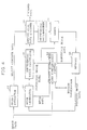
- Figure 4 is a block diagram showing a motion image encoding apparatus according to another preferred embodiment of the present invention. Since the blocks of Figure 4 having the same reference numerals as those of the Figure 1 blocks perform the same functions as those of the corresponding blocks of figure 1, the detailed description thereof will be omitted.
- the Figure 1 apparatus uses the meshes obtained from the current image and the reference image data stored in the memory 16 to generate predictive image data. On the contrary, the Figure 4 apparatus uses meshes obtained from reference image data stored in a memory 48 and externally input current image data to generate predictive image data.
- the external current image data is input to the object extractor 10 and a motion estimation and compensation portion 44.
- the object extractor 10 generates object contour data using the current image data.
- the object contour data is output to the differential data encoder 20.
- a mesh generator 42 reads the reference image data stored in the memory 48 and divides the entire reference into irregular meshes. For such division, the mesh generator 42 divides the reference image into regular rectangular meshes and divides the regular rectangular meshes into regular triangular meshes again. Since the method for generation of the regular rectangular mesh and the regular triangular mesh is same as a signal processing of the Figure 1 mesh generator 12, the detailed description thereof will be omitted.
- Another function of the mesh generator 42 generates an irregular mesh from regular rectangular meshes or regular triangular meshes.
- the procedure of generating the irregular mesh is as follows.
- the mesh generator 42 removes one selected among the control points of the regular triangular meshes, and performs triangulation with respect to the region from which the control point is removed.
- the triangular meshes generated by the triangulation have irregular triangular shapes.
- Such control point removal and triangulation repeats until the number of the remaining control points is identical to a predetermined value.
- a quantified difference value between image descriptiveness obtained when the control point has been removed from a support region of the control point and that when the former has not been removed.
- the support region is a region surrounded by neighbouring control points to a corresponding control point and lines connecting the neighbouring control points.
- a control point corresponding to the smallest difference value among the quantified difference values of the image descriptiveness does little to contribute for the image descriptiveness, to accordingly be removed.
- the irregular mesh generation technique is disclosed in a paper entitled " Irregular Triangular Mesh Representation Based on Adaptive Control Point Removal” published in SPIE's 1996 symposium on Visual Communications and Image Processing by Kang W. Chun, Byungwoo Jean and Jae M. Jo .
- the mesh generator 42 outputs information about the finally generated irregular triangular meshes, that is, the irregular mesh data representing the remaining control points and the irregular meshes surrounded by the control points, to a motion estimation and compensation portion 44.
- the mesh generator 42 outputs the reference image data read from the memory 48 to a difference value calculator 46 as well.
- the motion estimation and compensation portion 44 receives the externally supplied current image data and the irregular mesh data of the mesh generator 42, and reads the reference image data stored in the memory 48.
- the motion estimation and compensation portion 44 determines corresponding positions in the current image having the image data which is most similar to the control points of the irregular meshes. After the corresponding positions are determined, the motion estimation and compensation portion 44 generates motion vectors between the control points and the corresponding positions and uses spatial transformation to generate a predictive image using the current image.
- the predictive image data is supplied to the difference value calculator 46 and the adder 24, and the motion information representing the motion vectors are transmitted via a transmission channel or recorded on a storage medium to be used for a decoding apparatus.
- the difference value calculator 46 generates difference value data between the reference image data received from the mesh generator 42 and the predictive image data from the motion estimation and compensation portion 44, to supply the difference value data to a differential data encoder 20.
- the differential data encoder 20 encodes the object contour data output from the object extractor 10 and the difference value data output from the difference value calculator 46.
- the differential data encoder 20 processes the input data in the same manner as those of the corresponding blocks of Figure 1.
- the encoded data output from the differential data encoder 20 includes data obtained by encoding the difference value data in the object region and the encoded object contour data.
- the encoded data is transmitted to a receiver via a transmission channel (not shown), or is recorded on a recording medium (not shown).
- the encoded difference value data among the encoded data is transmitted to the differential data decoder 22.
- the differential data decoder 22 decodes the difference value data encoded in the differential data encoder 20, to supply the decoded difference value data to the adder 24.
- the adder 24 adds the predictive image data supplied from the motion estimation and compensation portion 44 and the difference value data of the differential data decoder 22, and the resultant data is stored in the memory 48, to be used as reference image data for motion estimation and motion compensation for a next image.
- Figure 5 shows a motion image decoding apparatus corresponding to the Figure 4 apparatus. Since blocks having the same reference numerals as those of the Figure 3 blocks among the blocks shown in Figure 5 have the same functions as those of the Figure 3 blocks, the detailed description thereof will be omitted.
- the encoded object contour data is input to an object contour restorer 30 and the motion information is input to a motion compensator 52. Also, the encoded difference value data is supplied to the differential data decoder 32.
- the differential data decoder 32 decodes the encoded difference value data to output the decoded difference value data to an adder 56.
- the object contour restorer 30 decodes the encoded object contour data to output the decoded object contour data to a mesh generator 51.
- the mesh generator 51 reads the reference image data stored in a memory 54, and divides the object region in the reference image determined by the object contour data via the same signal processing as that of the Figure 4 mesh generator 42, into irregular meshes.
- the mesh data output from the mesh generator 51 is supplied to the motion compensator 52.
- the motion compensator 52 uses the mesh data, the motion information and the reference image data stored in the memory 54 to generate the predictive image data.
- the adder 56 adds the predictive image data and the difference value data output from the differential data decoder 32.
- the resultant current image is stored in the memory 54 to be used as reference image data for motion compensation of a next image.
- the encoding and decoding system performs motion estimation and motion compensation based on mesh representation with respect to an arbitrary object contained in an image. As a result, a more efficient encoding can be performed compared with a case when motion estimation and motion compensation is performed with respect to the entire image. Thus, an apparatus appropriate for applications requiring a very low bit rate can be designed.
Landscapes
- Engineering & Computer Science (AREA)
- Multimedia (AREA)
- Signal Processing (AREA)
- Compression Or Coding Systems Of Tv Signals (AREA)
- Compression, Expansion, Code Conversion, And Decoders (AREA)
Abstract
Description
- The present invention relates to an encoding and decoding system of a motion image containing an arbitrary object.
- Recently, international standards for transmitting a motion image at a very low bit rate have progressed so as to be applied to a video phone or a video conference system. To transmit a motion image at a very low rate, an object-oriented encoding technique for partitioning a meaningful object in the motion image and transmitting the partitioned object is widely under study. The object-oriented encoding technique is recognized as an essential technique in order to transmit a motion image at a very low bit rate. In the object-oriented encoding of motion image, a motion prediction technique for removing temporal correlation with respect to an object is required and a more accurate motion prediction technique is needed for enhancing an encoding efficiency as well.
- It is an aim of preferred embodiments of the present invention to provide an encoding apparatus for a motion image containing an arbitrary object in which the arbitrary object extracted from an image is represented as meshes and control points of the meshes are used for motion predictive encoding of the image.
- Another aim of embodiments of the present invention is to provide a decoding apparatus for decoding data encoded in the above encoding apparatus.
- According to a first aspect of the present invention, there is provided a motion image encoding apparatus for encoding a current image containing an object, the motion image encoding a current image containing an object, the motion image encoding apparatus comprising: an object extraction unit for extracting the object contained in the current image from received current image data and outputting object contour data indicating a contour of the extracted object; a predictive encoding unit for performing a predictive encoding operation using the current image data, prestored data of a reference image, and control points of meshes which divide one of the current image and the reference image, and generating motion information involved with the control points, differential data between the current image and the reference image, and predictive image data; an object difference generator for selecting differential data in an object region among the differential data supplied from the predictive encoding unit to encode the selected differential data based on the object contour data output from the object extraction unit, and generating the selected differential data and the encoded differential data; and an addition unit for receiving and adding the predictive image data output from the predictive encoding unit and the differential data selected in the object difference generator, and updating the reference image data prestored in the predictive encoding unit using the image data obtained by the addition result.
- Preferably, said predictive encoding means performs predictive encoding using spatial transformation to generate the predictive image data.
- Said predictive encoding means may comprise: a memory for storing reference image data; a mesh generator for determining regular meshes having vertices located in the object region of the current image as control points among the meshes for dividing the entire image into a predetermined size, based on the object contour data from said object extraction means and outputting mesh data representing determined regular meshes; a motion estimation and compensation portion for generating the motion information according to the motion estimation with respect to the reference image of the control points, and the predictive image data whose motion of the control points is compensated, using the reference image data stored in said memory and the mesh data output from said mesh generator; and a differential data generator for generating differential data between the current image data and the predictive image data.
- Preferably, said mesh generator comprises: a block former for outputting the image block data representing a plurality of blocks each having a predetermined size obtained by dividing the current image with respect to the received current image data; a block selector for selecting the image block data containing the image data of the object region determined by the object contour data among the image block data output from said block former, and outputting the selected image block data; an object image composer for composing the object image by merging the image blocks of the selected image block data; and a mesh composer for determining vertices contained in the object image constituted by the object image composer among vertices of a plurality of grids which divide the entire image in size, as control points, and determining the grids having the control points as rectangular meshes.
- Preferably, said mesh composer outputs the mesh data representing the regular triangular meshes obtained from the regular rectangular meshes.
- Said regular triangular mesh may be obtained by dividing the mesh at a diagonal direction of 45° or -45° based on data similarity between the control points of each regular rectangular mesh.
- Preferably, said predictive encoding means comprises: a memory for storing reference image data; a mesh generator for determining irregular meshes having vertices located in the reference image as control points using the reference image data stored in said memory and outputting mesh data representing determined irregular meshes; a motion estimation and compensation portion for generating the motion information according to the motion estimation with respect to the current image of the control points, and the predictive image data whose motion of the control points is compensated, using the current image data and the mesh data output from said mesh generator; and a differential data generator for generating differential data between the reference image data and the predictive image data.
- Said mesh generator may generate the mesh data representing the irregular meshes generated by irregular triangular mesh representation based on adaptive control removal.
- Said object difference generator means preferably performs orthogonal transform coding with respect to the selected differential data.
- Preferably, said object difference generator means comprises: a differential data encoder for selecting the differential data belonging to the object region determined by the object contour data among the differential data output from said predictive encoding means, and encoding the selected differential data and the object contour data, to output the encoded differential data and the encoded object contour data; and a differential data decoder for decoding the encoded differential data output from said differential encoder and outputting the selected differential data.
- According to a second aspect of the present invention, there is also provided a motion image decoding apparatus for decoding the output of a motion image encoding apparatus, the motion image decoding apparatus comprising: an object contour restoring unit for decoding received encoded object contour data and restoring object contour data indicating a contour of an object contained in a current image; a differential data decoding unit for decoding the received encoded differential data and outputting differential data; a motion compensation decoding unit for performing a motion compensation operation using the object contour data, prestored reference image data, control points of meshes which divide one of an object contour and a reference image, and motion information involved with the control points; and an addition unit for adding the predictive image data selected by the object contour data and the differential data, and updating the reference image data prestored in the motion compensation decoding unit using the image data obtained by the addition result.
- Preferably, said differential data decoding means performs orthogonal transform decoding with respect to the encoded differential data.
- Said motion compensation decoding means may perform motion compensation using spatial transformation to generate the predictive image data.
- Preferably, said motion compensation decoding means comprises: a memory for storing reference image data; a mesh generator for determining meshes having vertices located in the object region determined by the object contour data output from said object contour restoring means as control points among the meshes by dividing the entire image into a predetermined size, and outputting mesh data representing the determined meshes and the object contour data; and a motion compensation portion for generating the predictive image data whose motion is compensated with respect to the reference image of the control points, using the reference image data stored in said memory and the mesh data.
- Preferably, the mesh data output from said mesh generator contains the position information of the vertices belonging to the determined meshes.
- Said mesh generator preferably outputs mesh data involving the regular rectangular meshes.
- Said motion image decoding means preferably comprises: a memory for storing reference image data; a mesh generator for determining meshes for dividing the reference image belonging to the object region determined by the object contour data among the reference image data stored in said memory and outputting mesh data representing determined meshes; and a motion estimation and compensation portion for generating the predictive image data whose motion is compensated with respect to the reference image of the control points belonging to the meshes, using the received motion information, the reference image data stored in the memory, and the mesh data.
- Said mesh generator may generate the mesh data representing the irregular meshes generated by irregular triangular mesh representation based on adaptive control point removal with respect to the reference image belonging to the object region.
- For a better understanding of the invention, and to show how embodiments of the same may be carried into effect, reference will now be made, by way of example, to the accompanying diagrammatic drawings, in which:
- Figure 1 is a block diagram showing a motion image encoding apparatus according to a preferred embodiment of the present invention;
- Figure 2 is a detailed block diagram of the mesh producer of Figure 1;
- Figure 3 is a block diagram showing a motion image decoding apparatus for decoding data encoded by the Figure 1 apparatus;
- Figure 4 is a block diagram showing a motion image encoding apparatus according to another preferred embodiment of the present invention; and
- Figure 5 is a block diagram showing a motion image decoding apparatus for decoding data encoded by the Figure 4 apparatus.
- Preferred embodiments of the present invention will be described in detail with reference to the accompanying drawings.
- In Figure 1 showing a motion image encoding apparatus according to a preferred embodiment of the present invention, an
object extractor 10 receives digital image data from an external source, and extracts an arbitrary object from a current image represented by the received image data. Then, theobject extractor 10 generates object contour data representing contour information of the extracted object. The object contour data is supplied to adifferential data encoder 20 and a decoding apparatus of Figure 3 to be described later. The object contour data contains spatial positions of pixels which determine a contour of the object or spatial positions of segments composed of the pixels. Theobject extractor 10 outputs the object contour data and the received current image data to amesh generator 12. Themesh generator 12 discriminates an object region from the current image based on the object contour data, and performs a signal processing for regular mesh representation with respect to the image in the object region. The detailed structure and operation of themesh generator 12 will be described with reference to Figure 2. - A block former 121 in the
mesh generator 12 receives the current image data and the object contour data output from theobject extractor 10. The block former 121 divides the current image represented by the received image data into image blocks each having a predetermined size, and supplies image block data representing image blocks and the object contour data to ablock selector 123. Theblock selector 123 selects image blocks containing the image data in the object region among the entire image blocks constituting the current image based on the object contour data. The data representing the selected image blocks and the object contour data is output to anobject image composer 125. Here, image blocks having only image data which do not belong to the object region, are not selected. Therefore, the data representing the image blocks which are not selected is not supplied to theobject image composer 125. Theobject image composer 125 which receives the data of the selected image blocks merges the selected image blocks and supplies the data representing the object image generated from the merging result and the object contour data to amesh composer 127. Themesh composer 127 receiving the object image data divides the object image into a regular rectangular mesh or a regular triangular mesh. - In the case that an image is divided using regular rectangular meshes, the
mesh composer 127 divides the object image into grids each having a predetermined size different from a block size. Here, a grid has a size smaller than that of a block. Then, themesh composer 127 determines vertices contained in the object region among the vertices of the grids obtained by the division as control points, and determines grids having the control points as regular rectangular meshes. Themesh composer 127 outputs rectangular mesh data containing the image data involving the control points of the regular rectangular meshes to a motion estimation andcompensation portion 14 of Figure 1. Here, the image data involving each control point includes the position of a control point and a gray value at the position of the control point, and the positions of the pixels having positions adjacent to the control point and the gray values. Themesh composer 127 also outputs the current image data to adifference value calculator 18. - In the case that an image is divided using regular triangular meshes, the
mesh composer 127 divides each regular rectangular mesh obtained through the above process into two regular triangular meshes based on similarity of the image data in the mesh. To judge similarity of the image data of each regular rectangular mesh, themesh composer 127 compares a difference value between pixel values corresponding to two control points which are located at a diagonal direction of 45° in the regular rectangular mesh, with a difference value between pixel values corresponding to two control points located at a diagonal direction of -45° therein in size. Themesh composer 127 divides the rectangular mesh in the diagonal direction corresponding to the smaller difference value. As a result, two regular triangular meshes are generated every rectangular mesh. Themesh composer 127 outputs the triangular mesh data containing the image data involving the control points of the regular triangular meshes to the motion estimation andcompensation portion 14. Themesh composer 127 outputs the current image data to adifference value calculator 18 as well. - The motion estimation and
compensation portion 14 performs a motion estimation and compensation using the reference image data stored in thememory 16 and the mesh data involving the object image in the current image received from the mesh former 12. The motion estimation andcompensation portion 14 first compares in magnitude the image data involved in the control points of each mesh with the reference image data stored in thememory 16. Each control point corresponds to a single pixel ideally. That is, a control point is expressed by a spatial position of a pixel and a gray value. However, it is actually difficult to exactly find out a position having image data similar to the control point in the reference image by only pixel to pixel comparison. Thus, the image data involving each control point is image data which is involved in a pixel corresponding to the control point and a plurality of pixels neighbouring the pixel corresponding to the control point, as described in themesh composer 127. The motion estimation andcompensation portion 14 determines a position in the reference image having the image data which is most similar to the image data of the control point based on the data magnitude comparison result. Then, the motion estimation andcompensation portion 14 determines a motion vector representing movement between a control point and a corresponding position in the reference image. If the motion vectors are determined with respect to all the control points, the motion estimation andcompensation portion 14 performs spatial transformation such as image warping using the determined motion vectors, and generates a predictive image with respect to the current image. The data representing the predictive image is output to thedifference value calculator 18 and theadder 24. The motion information representing the motion vectors corresponding to all the control points is supplied to the Figure 3 apparatus. Since the above-described spatial transformation is well known in the field of a digital image processing, the detailed description thereof will be omitted. - The
difference value calculator 18 calculates difference values between the current image data received from themesh generator 12 and the predicitve image data output from the motion estimation andcompensation portion 14. The difference value calculation is performed between the pixels having corresponding positions with respect to the current image and the predictive image, and the resultant difference value data is output to adifferential data encoder 20. Thedifferential data encoder 20 encodes difference value data in the object region determined by the object contour data of theobject extractor 10 among the difference value data supplied from thedifference value calculator 18. If the data encoded by thedifferential data encoder 20 is defined as difference value data in the object region, only difference value data involving the object of the current image is encoded. Accordingly, thedifferential data encoder 20 can perform a more efficient encoding operation with respect to the current image. Thedifferential data encoder 20 encodes the object contour data received from theobject extractor 10 as well. To encode the difference value data and the object contour data in the object region, thedifferential data encoder 20 uses a well-known orthogonal transform coding method including discrete cosine transform (DCT) and so on. The encoded object contour data, the encoded difference value data and the motion information are transmitted to a decoding apparatus of Figure 3 to be described later via a transmission channel (not shown), or are recorded on a storage medium used in the decoding apparatus of Figure 3. - A
differential data decoder 22 receiving the encoded difference value data from thedifferential data encoder 20 restores the difference value data via a reverse procedure of the signal processing of thedifferential data encoder 20. Theadder 24 adds the predicitve image data output from the motion estimation andcompensation portion 14 and the difference value data of thedifferential data decoder 22, and outputs the added result to thememory 16. The data output from theadder 24 is data of the current image from which motion estimation and compensation has been performed, and is stored in thememory 16 to be used as reference image data for motion estimation and motion compensation with respect to a next image. - A motion image decoding apparatus shown in Figure 3 receives the encoded difference value data, the encoded object contour data and the motion information generated by the Figure 1 apparatus. An
object contour restorer 30 decodes the encoded object contour data. The object contour data is output to amesh generator 34. Themesh generator 34 receiving the object contour data divides the entire image into grids each having a predetermined size, determines vertices existing in the object region determined by the object contour data as control points among the vertices of the grids obtained by the division, and determines the grids having the control points as rectangular meshes. In the case that themesh generator 12 of Figure 1 is designed to generate mesh data representing the rectangular meshes, themesh generator 34 also generates mesh data representing rectangular meshes. Meanwhile, in the case that themesh generator 12 of Figure 1 is designed to generate the mesh data involvoing the triangular meshes, themesh generator 34 generates mesh data involving the triangular meshes, themesh generator 34 supplies the generated mesh data to amotion compenstor 38 and supplies the object contour data to anadder 36. - Meanwhile, a
differential data decoder 32 decodes the encoded difference value data generatd by the Figure 1 apparatus. The difference value data is output to theadder 36. Themotion compensator 38 receives the mesh data output from themesh generator 34 and the motion information generated by the Figure 1 apparatus. Themotion compensator 38 generates predictive image data using control points contained in the mesh data corresponding to a current image, motion vectors corresponding to all the control points and contained in motion information, and the reference image data stored in thememory 40. To generate the predictive image data, themotion compensator 38 uses a motion vector corresponding to each control point to find out a position in the reference image which is most similar to the control point, and then uses spatial transformation such as image warping to generate predictive image data for a current image. Themotion compensator 38 outputs the generated predictive image data to anadder 36. - The
adder 36 receives the predictive image data output from themotion compensator 38 and the difference value data output from thedifferential data decoder 32. Theadder 36 adds only predictive image data in the object region determined by the object contour data supplied from themesh generator 34 among the entire predictive image data to the difference value data corresponding thereto. By doing so, image data with respect to an object in the current image can be restored. The output data of theadder 36 is stored in thememory 40 to be used as reference image data for motion compensation of a next image. - Figure 4 is a block diagram showing a motion image encoding apparatus according to another preferred embodiment of the present invention. Since the blocks of Figure 4 having the same reference numerals as those of the Figure 1 blocks perform the same functions as those of the corresponding blocks of figure 1, the detailed description thereof will be omitted. The Figure 1 apparatus uses the meshes obtained from the current image and the reference image data stored in the
memory 16 to generate predictive image data. On the contrary, the Figure 4 apparatus uses meshes obtained from reference image data stored in amemory 48 and externally input current image data to generate predictive image data. - The external current image data is input to the
object extractor 10 and a motion estimation andcompensation portion 44. Theobject extractor 10 generates object contour data using the current image data. The object contour data is output to thedifferential data encoder 20. Amesh generator 42 reads the reference image data stored in thememory 48 and divides the entire reference into irregular meshes. For such division, themesh generator 42 divides the reference image into regular rectangular meshes and divides the regular rectangular meshes into regular triangular meshes again. Since the method for generation of the regular rectangular mesh and the regular triangular mesh is same as a signal processing of the Figure 1mesh generator 12, the detailed description thereof will be omitted. - Another function of the
mesh generator 42 generates an irregular mesh from regular rectangular meshes or regular triangular meshes. The procedure of generating the irregular mesh is as follows. Themesh generator 42 removes one selected among the control points of the regular triangular meshes, and performs triangulation with respect to the region from which the control point is removed. The triangular meshes generated by the triangulation have irregular triangular shapes. Such control point removal and triangulation repeats until the number of the remaining control points is identical to a predetermined value. To remove a particular control point, a quantified difference value between image descriptiveness obtained when the control point has been removed from a support region of the control point and that when the former has not been removed. Here, the support region is a region surrounded by neighbouring control points to a corresponding control point and lines connecting the neighbouring control points. A control point corresponding to the smallest difference value among the quantified difference values of the image descriptiveness does little to contribute for the image descriptiveness, to accordingly be removed. The irregular mesh generation technique is disclosed in a paper entitled "Irregular Triangular Mesh Representation Based on Adaptive Control Point Removal" published in SPIE's 1996 symposium on Visual Communications and Image Processing by Kang W. Chun, Byungwoo Jean and Jae M. Jo. Themesh generator 42 outputs information about the finally generated irregular triangular meshes, that is, the irregular mesh data representing the remaining control points and the irregular meshes surrounded by the control points, to a motion estimation andcompensation portion 44. Themesh generator 42 outputs the reference image data read from thememory 48 to adifference value calculator 46 as well. - The motion estimation and
compensation portion 44 receives the externally supplied current image data and the irregular mesh data of themesh generator 42, and reads the reference image data stored in thememory 48. The motion estimation andcompensation portion 44 determines corresponding positions in the current image having the image data which is most similar to the control points of the irregular meshes. After the corresponding positions are determined, the motion estimation andcompensation portion 44 generates motion vectors between the control points and the corresponding positions and uses spatial transformation to generate a predictive image using the current image. The predictive image data is supplied to thedifference value calculator 46 and theadder 24, and the motion information representing the motion vectors are transmitted via a transmission channel or recorded on a storage medium to be used for a decoding apparatus. - The
difference value calculator 46 generates difference value data between the reference image data received from themesh generator 42 and the predictive image data from the motion estimation andcompensation portion 44, to supply the difference value data to adifferential data encoder 20. Thedifferential data encoder 20 encodes the object contour data output from theobject extractor 10 and the difference value data output from thedifference value calculator 46. Thedifferential data encoder 20 processes the input data in the same manner as those of the corresponding blocks of Figure 1. Thus, the encoded data output from thedifferential data encoder 20 includes data obtained by encoding the difference value data in the object region and the encoded object contour data. The encoded data is transmitted to a receiver via a transmission channel (not shown), or is recorded on a recording medium (not shown). The encoded difference value data among the encoded data is transmitted to thedifferential data decoder 22. - The
differential data decoder 22 decodes the difference value data encoded in thedifferential data encoder 20, to supply the decoded difference value data to theadder 24. Theadder 24 adds the predictive image data supplied from the motion estimation andcompensation portion 44 and the difference value data of thedifferential data decoder 22, and the resultant data is stored in thememory 48, to be used as reference image data for motion estimation and motion compensation for a next image. - Figure 5 shows a motion image decoding apparatus corresponding to the Figure 4 apparatus. Since blocks having the same reference numerals as those of the Figure 3 blocks among the blocks shown in Figure 5 have the same functions as those of the Figure 3 blocks, the detailed description thereof will be omitted. The encoded object contour data is input to an
object contour restorer 30 and the motion information is input to amotion compensator 52. Also, the encoded difference value data is supplied to thedifferential data decoder 32. Thedifferential data decoder 32 decodes the encoded difference value data to output the decoded difference value data to anadder 56. Theobject contour restorer 30 decodes the encoded object contour data to output the decoded object contour data to amesh generator 51. Themesh generator 51 reads the reference image data stored in amemory 54, and divides the object region in the reference image determined by the object contour data via the same signal processing as that of the Figure 4mesh generator 42, into irregular meshes. The mesh data output from themesh generator 51 is supplied to themotion compensator 52. Themotion compensator 52 uses the mesh data, the motion information and the reference image data stored in thememory 54 to generate the predictive image data. Theadder 56 adds the predictive image data and the difference value data output from thedifferential data decoder 32. The resultant current image is stored in thememory 54 to be used as reference image data for motion compensation of a next image. - As described above, the encoding and decoding system according to the present invention performs motion estimation and motion compensation based on mesh representation with respect to an arbitrary object contained in an image. As a result, a more efficient encoding can be performed compared with a case when motion estimation and motion compensation is performed with respect to the entire image. Thus, an apparatus appropriate for applications requiring a very low bit rate can be designed.
- Although a few preferred embodiments have been shown and described, it will be appreciated by those skilled in the art that various changes and modifications might be made without departing from the scope of the invention, as defined in the appended claims.
- The reader's attention is directed to all papers and documents which are filed concurrently with or previous to this specification in connection with this application and which are open to public inspection with this specification, and the contents of all such papers and documents are incorporated herein by reference.
- All of the features disclosed in this specification (including any accompanying claims, abstract and drawings), and/or all of the steps of any method or process so disclosed, may be combined in any combination, except combinations where at least some of such features and/or steps are mutually exclusive.
- Each feature disclosed in this specification (including any accompanying claims, abstract and drawings), may be replaced by alternative features serving the same, equivalent or similar purpose, unless expressly stated otherwise. Thus, unless expressly stated otherwise, each feature disclosed is one example only of a generic series of equivalent or similar features.
- The invention is not restricted to the details of the foregoing embodiment(s). The invention extends to any novel one, or any novel combination, of the features disclosed in this specification (including any accompanying claims, abstract and drawings), or to any novel one, or any novel combination, of the steps of any method or process so disclosed.
Claims (10)
- A motion image encoding apparatus for encoding a current image containing an object, the motion image encoding apparatus comprising:object extraction means (10) for extracting the object contained in the current image from received current image data and outputting object contour data indicating a contour of the extracted object;predictive encoding means (12, 14, 16, 18; 42, 44, 46, 48) for performing a predictive encoding operation using the current image data, prestored data of a reference image, and control points of meshes which divide one of the current image and the reference image, and generating motion information relating to the control points, differential data between the current image and the reference image, and predictive image data;object difference generator means (20, 22) for selecting differential data in an object region among the differential data supplied from the predictive encoding means (12, 14, 16, 18; 42, 44, 46, 48) to encode the selected differential data based on the object contour data output from the object extraction means (10), and outputting the selected differential data and the encoded differential data; andadder means (24) for receiving and adding the predictive image data output from the predictive encoding means and the selected differential data output from the object difference generator means, and updating the reference image data prestored in the predictive encoding means using the image data obtained by the addition result.
- The motion image encoding apparatus according to claim 1, wherein said predictive encoding means (12-18; 42-48) performs predictive encoding using spatial transformation to generate the predictive image data.
- The motion image encoding apparatus according to claim 1 or 2, wherein said predictive encoding means (12-18) comprises:a memory (16) for storing reference image data;a mesh generator (12) for determining regular meshes having vertices located in the object region of the current image as control points among the meshes for dividing the entire image into a predetermined size, based on the object contour data from said object extraction means (10) and outputting mesh data representing determined regular meshes;a motion estimation and compensation portion (14) for generating the motion information according to the motion estimation with respect to the reference image of the control points, and the predictive image data whose motion of the control points is compensated, using the reference image data stored in said memory (16) and the mesh data output from said mesh generator (12); anda differential data generator (18) for generating differential data between the current image data and the predictive image data.
- The motion image encoding apparatus according to claim 3, wherein said mesh generator (12) comprises:a block former (121) for outputting the image block data representing a plurality of blocks each having a predetermined size obtained by dividing the current image with respect to the received current image data;a block selector (123) for selecting the image block data containing the image data of the object region determined by the object contour data among the image block data output from said block former (121), and outputting the selected image block data;an object image composer (125) for composing the object image by merging the image blocks of the selected image block data; anda mesh composer (127) for determining vertices contained in the object image constituted by the object image composer (125) among vertices of a plurality of grids which divide the entire image in size, as control points, and determining the grids having the control points as rectangular meshes.
- The motion image encoding apparatus according to claim 4, wherein said mesh composer (127) outputs the mesh data representing the regular triangular meshes obtained from the regular rectangular meshes.
- The motion image encoding apparatus according to claim 5, wherein said regular triangular mesh is obtained by dividing the mesh at a diagonal direction of 45° or - 45° based on data similarity between the control points of each regular rectangular mesh.
- The motion image encoding apparatus according to claim 1, wherein said predictive encoding means comprises:a memory (48) for storing reference image data;a mesh generator (42) for determining irregular meshes having vertices located in the reference image as control points using the reference image data stored in said memory (48) and outputting mesh data representing determined irregular meshes;a motion estimation and compensation portion (44) for generating the motion information according to the motion estimation with respect to the current image of the control points, and the predictive image data whose motion of the control points is compensated, using the current image data and the mesh data output from said mesh generator (42); anda differential data generator (46) for generating differential data between the reference image data and the predictive image data.
- The motion image encoding apparatus according to claim 7, wherein said mesh generator (42) generates the mesh data representing the irregular meshes generated by irregular triangular mesh representation based on adaptive control removal.
- The motion image encoding apparatus according to any of claims 1 to 8, wherein said object difference generator means performs orthogonal transform coding with respect to the selected differential data.
- The motion image encoding apparatus according to any of claims 1 to 9, wherein said object difference generator means comprises:a differential data encoder (20) for selecting the differential data belonging to the object region determined by the object contour data among the differential data output from said predictive encoding means, and encoding the selected differential data and the object contour data, to output the encoded differential data and the encoded object contour data; anda differential data decoder (22) for decoding the encoded differential data output from said differential encoder and outputting the selected differential data.
Applications Claiming Priority (2)
| Application Number | Priority Date | Filing Date | Title |
|---|---|---|---|
| KR1019960018612A KR100215451B1 (en) | 1996-05-29 | 1996-05-29 | System for encoding and decoding moving image including objects of any shape |
| EP19970303590 EP0810792B1 (en) | 1996-05-29 | 1997-05-27 | Encoding and decoding system of motion image containing objects of arbitrary shapes |
Related Parent Applications (1)
| Application Number | Title | Priority Date | Filing Date |
|---|---|---|---|
| EP19970303590 Division EP0810792B1 (en) | 1996-05-29 | 1997-05-27 | Encoding and decoding system of motion image containing objects of arbitrary shapes |
Publications (2)
| Publication Number | Publication Date |
|---|---|
| EP1715695A2 true EP1715695A2 (en) | 2006-10-25 |
| EP1715695A3 EP1715695A3 (en) | 2008-10-22 |
Family
ID=37402254
Family Applications (3)
| Application Number | Title | Priority Date | Filing Date |
|---|---|---|---|
| EP20050000322 Withdrawn EP1523196A3 (en) | 1996-05-29 | 1997-05-27 | Encoding system of motion image containing arbitrary object |
| EP20060117952 Withdrawn EP1715695A3 (en) | 1996-05-29 | 1997-05-27 | Encoding system of motion image containing arbitrary shape objects |
| EP19970303590 Expired - Lifetime EP0810792B1 (en) | 1996-05-29 | 1997-05-27 | Encoding and decoding system of motion image containing objects of arbitrary shapes |
Family Applications Before (1)
| Application Number | Title | Priority Date | Filing Date |
|---|---|---|---|
| EP20050000322 Withdrawn EP1523196A3 (en) | 1996-05-29 | 1997-05-27 | Encoding system of motion image containing arbitrary object |
Family Applications After (1)
| Application Number | Title | Priority Date | Filing Date |
|---|---|---|---|
| EP19970303590 Expired - Lifetime EP0810792B1 (en) | 1996-05-29 | 1997-05-27 | Encoding and decoding system of motion image containing objects of arbitrary shapes |
Country Status (7)
| Country | Link |
|---|---|
| US (3) | US6038258A (en) |
| EP (3) | EP1523196A3 (en) |
| JP (1) | JPH1056643A (en) |
| KR (1) | KR100215451B1 (en) |
| CN (2) | CN1146242C (en) |
| DE (1) | DE69736852T2 (en) |
| ES (1) | ES2277350T3 (en) |
Families Citing this family (30)
| Publication number | Priority date | Publication date | Assignee | Title |
|---|---|---|---|---|
| KR100215451B1 (en) * | 1996-05-29 | 1999-08-16 | 윤종용 | System for encoding and decoding moving image including objects of any shape |
| KR100620715B1 (en) * | 1998-06-30 | 2007-04-25 | 주식회사 팬택앤큐리텔 | Encoding / Decoding Method of Digital Gray Shape Information / Color Information |
| KR100535630B1 (en) * | 1998-06-30 | 2006-06-23 | 주식회사 팬택앤큐리텔 | Encoding / Decoding Method of Digital Gray Shape Information / Color Information |
| WO2000025232A1 (en) * | 1998-10-23 | 2000-05-04 | Siemens Aktiengesellschaft | Method and array for coding, decoding, and transmitting a digitized image |
| US6351267B1 (en) | 1998-12-10 | 2002-02-26 | Gizmoz Ltd | Fast transmission of graphic objects |
| JP4126126B2 (en) * | 1998-12-11 | 2008-07-30 | 株式会社日立製作所 | Transmission system and transmission method |
| JP3897476B2 (en) * | 1999-02-15 | 2007-03-22 | キヤノン株式会社 | Image processing apparatus and method, and computer-readable memory |
| KR100611999B1 (en) | 1999-08-27 | 2006-08-11 | 삼성전자주식회사 | Motion compensating method in object based quad-tree mesh using greedy algorithm |
| FR2802377B1 (en) * | 1999-12-09 | 2002-03-08 | France Telecom | METHOD FOR ESTIMATING MOTION BETWEEN TWO IMAGES WITH MANAGEMENT OF MESH RETURNS AND CORRESPONDING CODING METHOD |
| US6909746B2 (en) | 2001-03-30 | 2005-06-21 | Koninklijke Philips Electronics N.V. | Fast robust data compression method and system |
| WO2003021970A1 (en) * | 2001-09-04 | 2003-03-13 | Faroudja Cognition Systems, Inc. | Low bandwidth video compression |
| CN1838775B (en) * | 2001-11-30 | 2011-11-23 | 株式会社Ntt都科摩 | Moving picture coding apparatus, moving picture decoding apparatus, moving picture coding method and moving picture decoding method |
| FI114679B (en) * | 2002-04-29 | 2004-11-30 | Nokia Corp | Random start points in video encoding |
| US7383275B2 (en) | 2002-05-10 | 2008-06-03 | International Business Machines Corporation | Methods to improve indexing of multidimensional databases |
| US7373353B2 (en) | 2002-05-10 | 2008-05-13 | International Business Machines Corporation | Reducing index size for multi-level grid indexes |
| US7143098B2 (en) * | 2002-05-10 | 2006-11-28 | International Business Machines Corporation | Systems, methods, and computer program products to reduce computer processing in grid cell size determination for indexing of multidimensional databases |
| US7095786B1 (en) | 2003-01-11 | 2006-08-22 | Neo Magic Corp. | Object tracking using adaptive block-size matching along object boundary and frame-skipping when object motion is low |
| JP2005184626A (en) * | 2003-12-22 | 2005-07-07 | Canon Inc | Image processing apparatus |
| US20050198008A1 (en) * | 2004-03-02 | 2005-09-08 | Adler David W. | Index exploitation for spatial data |
| US7389283B2 (en) * | 2004-12-07 | 2008-06-17 | International Business Machines Corporation | Method for determining an optimal grid index specification for multidimensional data |
| EP2720468B1 (en) * | 2005-09-26 | 2017-03-29 | Mitsubishi Electric Corporation | Moving image decoding method |
| DE602006008040D1 (en) * | 2005-12-19 | 2009-09-03 | Koninkl Philips Electronics Nv | PROCESS FOR FACILITATING REPRODUCTION OF IMAGES ON DEFORMABLE NETS |
| KR20080107965A (en) * | 2007-06-08 | 2008-12-11 | 삼성전자주식회사 | Method and apparatus for encoding and decoding image using object boundary based partition |
| JP5230372B2 (en) * | 2008-11-25 | 2013-07-10 | キヤノン株式会社 | Image processing apparatus and image processing method |
| JP5558949B2 (en) * | 2010-07-16 | 2014-07-23 | キヤノン株式会社 | Image processing apparatus, image processing method, and program |
| JP5661359B2 (en) * | 2010-07-16 | 2015-01-28 | キヤノン株式会社 | Image processing apparatus, image processing method, and program |
| US9189884B2 (en) * | 2012-11-13 | 2015-11-17 | Google Inc. | Using video to encode assets for swivel/360-degree spinners |
| CN106331722B (en) | 2015-07-03 | 2019-04-26 | 华为技术有限公司 | Image prediction method and relevant device |
| CN111526361B (en) | 2016-02-06 | 2022-05-13 | 华为技术有限公司 | Image coding and decoding method and device |
| KR102660416B1 (en) | 2024-02-02 | 2024-04-23 | 박흥순 | Method and system for continuous processing of steel plates for manufacturing large steel structures |
Family Cites Families (26)
| Publication number | Priority date | Publication date | Assignee | Title |
|---|---|---|---|---|
| JP3037383B2 (en) * | 1990-09-03 | 2000-04-24 | キヤノン株式会社 | Image processing system and method |
| JP3405788B2 (en) * | 1993-03-04 | 2003-05-12 | 株式会社東芝 | Video encoding device and video decoding device |
| DE69416717T2 (en) * | 1993-05-21 | 1999-10-07 | Nippon Telegraph And Telephone Corp., Tokio/Tokyo | Moving picture encoders and decoders |
| JPH08297692A (en) * | 1994-09-16 | 1996-11-12 | Mitsubishi Electric Corp | Device and method for correcting optical proximity, and pattern forming method |
| KR0159575B1 (en) * | 1994-10-31 | 1999-01-15 | 배순훈 | Discrete processing apparatus between neighbor region in region based coding |
| KR100235343B1 (en) * | 1994-12-29 | 1999-12-15 | 전주범 | Apparatus for calculating motion vector in encoder using segmentation method |
| EP0721287A1 (en) * | 1995-01-09 | 1996-07-10 | Daewoo Electronics Co., Ltd | Method and apparatus for encoding a video signal |
| US5635929A (en) * | 1995-02-13 | 1997-06-03 | Hughes Aircraft Company | Low bit rate video encoder and decoder |
| JP3086396B2 (en) * | 1995-03-10 | 2000-09-11 | シャープ株式会社 | Image encoding device and image decoding device |
| KR0159370B1 (en) * | 1995-03-20 | 1999-01-15 | 배순훈 | Method and apparatus for encoding a video signals using a boundary of an object |
| GB2300287B (en) * | 1995-04-27 | 2000-04-26 | Canon Kk | Method and apparatus for processing finite element meshing model |
| US5654771A (en) * | 1995-05-23 | 1997-08-05 | The University Of Rochester | Video compression system using a dense motion vector field and a triangular patch mesh overlay model |
| JP2701795B2 (en) * | 1995-06-28 | 1998-01-21 | 日本電気株式会社 | Process simulation method |
| US5646867A (en) * | 1995-07-24 | 1997-07-08 | Motorola Inc. | Method and system for improved motion compensation |
| JP2798120B2 (en) * | 1995-08-04 | 1998-09-17 | 日本電気株式会社 | Motion compensated interframe prediction method and motion compensated interframe prediction device |
| US5691769A (en) * | 1995-09-07 | 1997-11-25 | Daewoo Electronics Co, Ltd. | Apparatus for encoding a contour of an object |
| KR100208375B1 (en) * | 1995-12-27 | 1999-07-15 | 윤종용 | Method and apparatus for encoding moving picture |
| JP2798035B2 (en) * | 1996-01-17 | 1998-09-17 | 日本電気株式会社 | Motion compensated inter-frame prediction method using adaptive motion vector interpolation |
| US5736987A (en) * | 1996-03-19 | 1998-04-07 | Microsoft Corporation | Compression of graphic data normals |
| EP0836784B1 (en) * | 1996-05-06 | 2003-09-17 | Koninklijke Philips Electronics N.V. | Segmented video coding and decoding method and system |
| KR100215451B1 (en) * | 1996-05-29 | 1999-08-16 | 윤종용 | System for encoding and decoding moving image including objects of any shape |
| US5936671A (en) * | 1996-07-02 | 1999-08-10 | Sharp Laboratories Of America, Inc. | Object-based video processing using forward-tracking 2-D mesh layers |
| US5907626A (en) * | 1996-08-02 | 1999-05-25 | Eastman Kodak Company | Method for object tracking and mosaicing in an image sequence using a two-dimensional mesh |
| US6047088A (en) * | 1996-12-16 | 2000-04-04 | Sharp Laboratories Of America, Inc. | 2D mesh geometry and motion vector compression |
| US6148026A (en) * | 1997-01-08 | 2000-11-14 | At&T Corp. | Mesh node coding to enable object based functionalities within a motion compensated transform video coder |
| US5818463A (en) * | 1997-02-13 | 1998-10-06 | Rockwell Science Center, Inc. | Data compression for animated three dimensional objects |
-
1996
- 1996-05-29 KR KR1019960018612A patent/KR100215451B1/en not_active IP Right Cessation
-
1997
- 1997-05-20 JP JP12993397A patent/JPH1056643A/en active Pending
- 1997-05-27 EP EP20050000322 patent/EP1523196A3/en not_active Withdrawn
- 1997-05-27 EP EP20060117952 patent/EP1715695A3/en not_active Withdrawn
- 1997-05-27 ES ES97303590T patent/ES2277350T3/en not_active Expired - Lifetime
- 1997-05-27 DE DE1997636852 patent/DE69736852T2/en not_active Expired - Lifetime
- 1997-05-27 EP EP19970303590 patent/EP0810792B1/en not_active Expired - Lifetime
- 1997-05-29 US US08/864,992 patent/US6038258A/en not_active Expired - Lifetime
- 1997-05-29 CN CNB991215907A patent/CN1146242C/en not_active Expired - Fee Related
- 1997-05-29 CN CNB971129061A patent/CN1134988C/en not_active Expired - Fee Related
-
2000
- 2000-02-16 US US09/504,934 patent/US6236680B1/en not_active Expired - Lifetime
-
2001
- 2001-04-26 US US09/842,405 patent/US6744817B2/en not_active Expired - Fee Related
Non-Patent Citations (4)
| Title |
|---|
| CHUN K W ET AL: "IRREGULAR TRIANGULAR MESH REPRESENTATION BASED ON ADAPTIVE CONTROL POINT REMOVAL" SPIE VISUAL COMMUNICATIONS AND IMAGE PROCESSING, XX, XX, vol. 2727, no. PART 02, 1 January 1996 (1996-01-01), pages 844-853, XP002043698 * |
| DUDON M ET AL: "MOTION ESTIMATION AND TRIANGULAR ACTIVE MESH" REVUE HF, SOC. BELGE DES ING. DES TELECOMM. & D'ELECTRONIQUE. OPHAIN, BE, no. 4, 1 January 1995 (1995-01-01), pages 47-53, XP002036860 ISSN: 0035-3248 * |
| HOETTER M: "OPTIMIZATION AND EFFICIENCY OF AN OBJECT-ORIENTED ANALYSIS-SYNTHESIS CODER" IEEE TRANSACTIONS ON CIRCUITS AND SYSTEMS FOR VIDEO TECHNOLOGY, IEEE SERVICE CENTER, PISCATAWAY, NJ, US, vol. 4, no. 2, 1 April 1994 (1994-04-01), pages 181-194, XP000489690 ISSN: 1051-8215 * |
| SALEMBIER P ET AL: "VERY LOW BIT RATE VIDEO CODING USING ACTIVE TRIANGULAR MESH" 1996 IEEE INTERNATIONAL CONFERENCE ON ACOUSTICS, SPEECH, AND SIGNAL PROCESSING - PROCEEDINGS. (ICASSP). ATLANTA, MAY 7 - 10, 1996; [IEEE INTERNATIONAL CONFERENCE ON ACOUSTICS, SPEECH, AND SIGNAL PROCESSING - PROCEEDINGS. (ICASSP)], NEW YORK, IEEE, US, vol. CONF. 21, 7 May 1996 (1996-05-07), pages 2060-2063, XP000681654 ISBN: 978-0-7803-3193-8 * |
Also Published As
| Publication number | Publication date |
|---|---|
| DE69736852D1 (en) | 2006-12-07 |
| US20010014119A1 (en) | 2001-08-16 |
| KR100215451B1 (en) | 1999-08-16 |
| ES2277350T3 (en) | 2007-07-01 |
| EP1523196A3 (en) | 2006-01-18 |
| US6038258A (en) | 2000-03-14 |
| EP0810792A2 (en) | 1997-12-03 |
| EP0810792B1 (en) | 2006-10-25 |
| EP0810792A3 (en) | 2000-12-13 |
| JPH1056643A (en) | 1998-02-24 |
| CN1134988C (en) | 2004-01-14 |
| KR970078652A (en) | 1997-12-12 |
| US6744817B2 (en) | 2004-06-01 |
| CN1177259A (en) | 1998-03-25 |
| CN1254238A (en) | 2000-05-24 |
| DE69736852T2 (en) | 2007-09-06 |
| EP1523196A2 (en) | 2005-04-13 |
| US6236680B1 (en) | 2001-05-22 |
| CN1146242C (en) | 2004-04-14 |
| EP1715695A3 (en) | 2008-10-22 |
Similar Documents
| Publication | Publication Date | Title |
|---|---|---|
| EP1715695A2 (en) | Encoding system of motion image containing arbitrary shape objects | |
| US5086439A (en) | Encoding/decoding system utilizing local properties | |
| US5592228A (en) | Video encoder using global motion estimation and polygonal patch motion estimation | |
| US7031532B2 (en) | Video coding and video decoding apparatus | |
| JP3277111B2 (en) | Video encoding device and video decoding device | |
| US8204118B2 (en) | Video encoding method and decoding method, apparatuses therefor, programs therefor, and storage media which store the programs | |
| EP0790580B1 (en) | System and method for compression of digital images using motion estimation | |
| CN101193302A (en) | Illumination compensation method and apparatus and video encoding and decoding method and apparatus | |
| US5732157A (en) | Image processing apparatus and method using lossless encoding of a difference between image blocks | |
| RU2335803C2 (en) | Method and device for frame-accurate encoding of residual movement based on superabundant basic transformation to increase video image condensation | |
| JP2008061133A (en) | Image encoding apparatus and image encoding method | |
| KR100215450B1 (en) | Method and apparatus of object-oriented image representation using irregular mesh | |
| KR20010053286A (en) | Image coding/decoding method and recorded medium on which program is recorded | |
| KR19980018127A (en) | A picture coding method, a picture decoding method, a picture coding apparatus using the method, a picture decoding apparatus and a recording medium for recording the method | |
| JPH08317410A (en) | Method and apparatus for coding image signal | |
| JPH09326024A (en) | Picture coding and decoding method and its device | |
| KR100689642B1 (en) | Encoding device and method, and decoding device and method | |
| KR20130022541A (en) | Method and apparatus for encoding image, and method and apparatus for decoding image | |
| CN105075256A (en) | Method for encoding a plurality of input images and storage medium and device for storing program | |
| JP2005236723A (en) | Device and method for encoding moving image, and device and method for decoding the moving image | |
| Midtvik et al. | Reversible compression of MR images | |
| KR100203713B1 (en) | Method and apparatus for processing an image signal having an object by using an extension-interpolation technique | |
| JP2001160966A (en) | Moving picture encoding device | |
| JPH06225288A (en) | Movement compensation predictive coder/decoder | |
| JP2001169118A (en) | Method and device for image processing and computer- readable memory |
Legal Events
| Date | Code | Title | Description |
|---|---|---|---|
| PUAI | Public reference made under article 153(3) epc to a published international application that has entered the european phase |
Free format text: ORIGINAL CODE: 0009012 |
|
| 17P | Request for examination filed |
Effective date: 20060727 |
|
| AC | Divisional application: reference to earlier application |
Ref document number: 0810792 Country of ref document: EP Kind code of ref document: P |
|
| AK | Designated contracting states |
Kind code of ref document: A2 Designated state(s): DE ES GB |
|
| PUAL | Search report despatched |
Free format text: ORIGINAL CODE: 0009013 |
|
| AK | Designated contracting states |
Kind code of ref document: A3 Designated state(s): DE ES GB |
|
| 17Q | First examination report despatched |
Effective date: 20090113 |
|
| AKX | Designation fees paid |
Designated state(s): DE ES GB |
|
| STAA | Information on the status of an ep patent application or granted ep patent |
Free format text: STATUS: THE APPLICATION IS DEEMED TO BE WITHDRAWN |
|
| 18D | Application deemed to be withdrawn |
Effective date: 20090526 |