EP1715396A1 - Actuator controller and a method for controlling such an actuator controller - Google Patents
Actuator controller and a method for controlling such an actuator controller Download PDFInfo
- Publication number
- EP1715396A1 EP1715396A1 EP20060007854 EP06007854A EP1715396A1 EP 1715396 A1 EP1715396 A1 EP 1715396A1 EP 20060007854 EP20060007854 EP 20060007854 EP 06007854 A EP06007854 A EP 06007854A EP 1715396 A1 EP1715396 A1 EP 1715396A1
- Authority
- EP
- European Patent Office
- Prior art keywords
- signal
- actuator
- controller
- actuator body
- driving
- Prior art date
- Legal status (The legal status is an assumption and is not a legal conclusion. Google has not performed a legal analysis and makes no representation as to the accuracy of the status listed.)
- Granted
Links
Images



Classifications
-
- G—PHYSICS
- G05—CONTROLLING; REGULATING
- G05B—CONTROL OR REGULATING SYSTEMS IN GENERAL; FUNCTIONAL ELEMENTS OF SUCH SYSTEMS; MONITORING OR TESTING ARRANGEMENTS FOR SUCH SYSTEMS OR ELEMENTS
- G05B19/00—Program-control systems
- G05B19/02—Program-control systems electric
- G05B19/18—Numerical control [NC], i.e. automatically operating machines, in particular machine tools, e.g. in a manufacturing environment, so as to execute positioning, movement or co-ordinated operations by means of program data in numerical form
- G05B19/406—Numerical control [NC], i.e. automatically operating machines, in particular machine tools, e.g. in a manufacturing environment, so as to execute positioning, movement or co-ordinated operations by means of program data in numerical form characterised by monitoring or safety
- G05B19/4062—Monitoring servoloop, e.g. overload of servomotor, loss of feedback or reference
-
- B—PERFORMING OPERATIONS; TRANSPORTING
- B60—VEHICLES IN GENERAL
- B60H—ARRANGEMENTS OF HEATING, COOLING, VENTILATING OR OTHER AIR-TREATING DEVICES SPECIALLY ADAPTED FOR PASSENGER OR GOODS SPACES OF VEHICLES
- B60H1/00—Heating, cooling or ventilating devices
- B60H1/00642—Control systems or circuits; Control members or indication devices for heating, cooling or ventilating devices
- B60H1/00814—Control systems or circuits characterised by their output, for controlling particular components of the heating, cooling or ventilating installation
- B60H1/00821—Control systems or circuits characterised by their output, for controlling particular components of the heating, cooling or ventilating installation the components being ventilating, air admitting or air distributing devices
- B60H1/00835—Damper doors, e.g. position control
- B60H1/00849—Damper doors, e.g. position control for selectively commanding the induction of outside or inside air
-
- G—PHYSICS
- G05—CONTROLLING; REGULATING
- G05B—CONTROL OR REGULATING SYSTEMS IN GENERAL; FUNCTIONAL ELEMENTS OF SUCH SYSTEMS; MONITORING OR TESTING ARRANGEMENTS FOR SUCH SYSTEMS OR ELEMENTS
- G05B2219/00—Program-control systems
- G05B2219/30—Nc systems
- G05B2219/42—Servomotor, servo controller kind till VSS
- G05B2219/42277—If no position command in a period, servo to rest position, shut off power
-
- G—PHYSICS
- G05—CONTROLLING; REGULATING
- G05B—CONTROL OR REGULATING SYSTEMS IN GENERAL; FUNCTIONAL ELEMENTS OF SUCH SYSTEMS; MONITORING OR TESTING ARRANGEMENTS FOR SUCH SYSTEMS OR ELEMENTS
- G05B2219/00—Program-control systems
- G05B2219/30—Nc systems
- G05B2219/42—Servomotor, servo controller kind till VSS
- G05B2219/42329—Defective measurement, sensor failure
Definitions
- the present invention relates to an actuator controller and a method for controlling such an actuator controller.
- Actuators which are instructed as to its activation position to perform movement or rotation, are generally each equipped with a location sensor, such as an encoder or a potentiometer, that indicates the position of the actuator itself. Many actuator controllers each control the actuator such that the position indicated by the location sensor may be in conformity with a target one. See JP-A 2005-073377 .
- the above actuator controller commonly makes a control, while positional signals of given bit counts are assigned over an driven range of the actuator.
- an actuator In an air blower for an automobile, such an actuator is used to drive an open air introducing door which turns over air suction ports.
- an internal air-circulating operation In the state that the rotation angle of the actuator is "zero", an internal air-circulating operation is performed in which a car interior air is circulated, while the open air introducing door is closed to introduce no air from the outside of the car into the car interior.
- open air introducing operation is performed, in which open air outside the car is introduced into the car interior, while the open air introducing door is fully opened. Now, this case will be considered.
- a first aspect of the present invention is directed to an actuator controller comprises:
- the actuator body is driven to the instructed position based on the position instructing signal. Further, the actuator body can be driven in a normal or reverse direction by either one of the arbitrary two bits in the in the predetermined bit counts. Even if the actuator body is not driven when the location sensor gets out of order, the actuator body can be driven in a predetermined direction.
- controller body When the controller body outputs the position instructing signal to the actuator driving unit and if the controller body does not receive the positional signal corresponding to the position instructing signal from the actuator body within a first predetermined time period, and the controller body stops outputting the position instructing signal to the actuator driving unit and outputs said normal direction forcedly driving signal or the reverse direction forcedly driving signal.
- the actuator controller can forcedly drive an actuator of which driven position is controlled based on a location sensor, if the location sensor for the actuator gets out of order.
- the controller body stops outputting of the normal direction forcedly driving signal or the reverse direction forcedly driving signal after lapse of a second time period.
- the actuator body may be that if the actuator body comes to be normally rotated during the forced rotation, the forced rotation is stopped, and the actuator body is returned to the normal driving.
- a second aspect of the present invention is directed to a method for controlling an actuator controller, said controller comprises:
- the actuator body is driven to the instructed position based on the position instructing signal. Further, the actuator body can be driven in a normal or reverse direction by either one of the arbitrary two bits in the predetermined bit counts. Even if the actuator body is not driven when the location sensor gets out of order, the actuator body can be driven in a predetermined direction.
- the actuator body if the actuator body does not reach the instructed position within the first predetermined time period, the actuator body is forcedly driven in a predetermined direction, so that the actuator body is prevented from stopping at an inappropriate position.
- the controller body stops outputting of the normal direction forcedly driving signal or the reverse direction forcedly driving signal after lapse of a second time period.
- the actuator controller and the method of controlling the actuating controller which can forcedly drive the actuator of which driven position is controlled based on the operated position even if the location sensor for the actuator gets out of order.
- FIG. 1 is a block diagram of a first embodiment of the actuator controller according to the present invention. In this embodiment, the embodiment will be explained with respect to an automobile air blower using a rotary type actuator.
- An actuator body 1 is equipped with a location sensor 1A for outputting rotation positional signals.
- the actuator body is rotated upon receipt of a driving signal (electric current) from an actuator driving unit 2 connected electrically to the actuator body, and the location sensor outputs a rotational positional signal.
- the actuator driving unit 2 receives a rotation instructing signal from the controller body 3 electrically connected to the actuator body 2, and outputs a driving signal (electric current) to the actuator body 1.
- the actuator driving unit 2 also receives a rotational positional signal from the location sensor 1A, and drives the actuator body 1 by regulating the driving signal (electric current) so that the actuator body 1 may be turned to the rotational position corresponding to the rotation instructing signal received from the controller unit 3.
- the controller unit 3 outputs to the actuator driving unit 2 a rotation instructing signal to turn the actuator body 1, and also receives a rotational positional signals from the location sensor 1A.
- FIG. 2 schematically shows the construction of an air blower of an automobile.
- the air blower 10 comprises an air blower body 10A and an air blower fan 10B.
- the air blower body 10A is equipped with a suction port 10C communicated with a car exterior and a suction port 10D communicating with a car interior.
- An open air introducing door 20 is provided downstream of the suction ports 10C and 10D. As the actuator body 1 is turned, the open air introducing door 20 is turned in a direction of an arrow A in FIG. 2.
- the air blower fan 10B is provided downstream of the open air-introducing door 20 and in a forward direction of the vehicle. The air taken in by the suction port 10C and 10D is fed into the car interior through the air blowing port 10E communicating with the car interior.
- the suction port 10C When the open air introducing door 20 is located at a position P1 in FIG. 2, the suction port 10C is closed with the open air introducing door 20. Therefore, the air blower body 10A takes in car interior air (hereinafter referred to as "interior air") through the suction port 10D, and the air blow fan 10B supplies it into the car interior through the air blow port 10E.
- internal air car interior air
- the air blower body 10A takes in open air (hereinafter referred to as "open air") through the air suction port 10C, and the air blow fan 10B supplies into the car interior it through the air blow port 10E.
- open air and interior air are taken through the suction ports 10C and 10D in respective amounts depending upon the positions of the open air introducing door 20 from the suction ports 10C and 10D, and the air is supplied into the car interior through the blower port 10E with the air blower fan 10B after the open air and the interior air are mixed together inside the air blower body 10A.
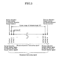
- FIG. 3 is a schematic diagram illustrating the contents of rotation instructing signals which the controller body 3 output to the actuator driving unit 2.
- the controller body 3 outputs a rotational position of ⁇ ° in the form of a N-bit signal in a rotational range over which the actuator body 1 is turned.
- a second bit to an (N-1)th bit are used as rotational position instructing signals for instructing rotational positions of the actuator body 1. Therefore, an angle of one bit for the rotational position instructing signal is [ ⁇ /(N-2)]°.
- One bit in the minimum count is used as a normal direction forcedly rotating signal to turn the actuator body 1 so that the suction port 10C may be closed with the open air introducing door 20 (Position P1 in FIG. 2).
- the Nth bit in the maximum count is used as a reverse direction forcedly driving signal to turn the actuator body 1 so that the suction port 10D may be closed with the open air introduction door 20 (Position P2 in FIG. 2).
- Step S101 the controller body 3 outputs a rotational position instructing signal to the actuator driving unit 2. Thereafter, the process goes to Step S102.
- Step S102 the actuator driving unit 2 drives the actuator body 1.
- the actuator driving unit 2 outputs a driving signal (electric current) to the actuator body 1 based on the rotational position instructing signal received from the controller body 3, thereby driving the actuator body 1.
- the actuator driving unit 2 receives a rotational positional signal from the location sensor 1A of the actuator body 1, and drives the actuator body 1 by adjusting the driving signal (amount of electric current) such that the rotational position instructing signal may be equal to the rotational positional signal. Then, the process goes to Step S103.
- Step S103 the location sensor 1A outputs the rotational positional signal to the controller body 3. Then, the process goes to Step S104.
- Step S104 judgment is made by comparing the rotational position instructing signal with the rotational positional signal. If the rotational position instructing signal is in conformity with the rotational positional signal, it is judged that the positional sensor 1A normally works. Thus, the process goes to Step S109 to terminate the present works. On the other hand, if the rotational position instructing signal is not in conformity with the rotational positional signal, the process goes to Step S105.
- Step S105 it is judged whether a predetermined time period T1 lapsed or not after the controller body 3 outputs the rotational position instructing signal to the actuator driving unit 2. If the predetermined time period T1 did not lapse, the process returns to Step S104. On the other hand, if more than the predetermined time period T1 lapsed but the rotational position instructing signal is not in conformity with the rotational positional signal, it is judged that the actuator body 1 is not properly controlled by the rotation position instructing signal. The process goes to Step 106.
- Step S106 the controller body 3 stops outputting of the rotational position instructing signal, and outputs the Nth bit of the reverse direction forcedly driving signal to the actuator driving unit 2.
- the actuator driving unit 2 receives this signal, it supplies electric current to the actuator body 1 so as to forcedly rotate the actuator body 1 in a direction in which the suction port 10D is closed with the open air introducing door 20 (Position P2 in FIG. 2). Then, the process goes to Step S107.
- Step S107 it is judged whether a predetermined time period T2 lapsed or not after the controller body 3 outputs the reverse direction forcedly rotational signal to the actuator driving unit 2.
- the actuator body 1 is continuously forcedly turned in the reverse direction until the predetermined time period T2 lapses.
- Step S108 the reverse direction forcedly rotation of the actuator body 1 is stopped, and the present operation is terminated at Step S109.
- the actuator body 1 is not turned even if the controller body 3 outputs a rotational position instructing signal, and the suction port 10C is closed with the open air introducing door 20 (Position P1 in FIG. 2).
- the open air introducing door 20 can be shifted to the fully opened state (Position P2 in FIG. 2) by forcedly turning the actuator body 1 through outputting the reverse direction forcedly rotational signal from the controller body 3. This operation can introduce open air, so that even if there is a large temperature difference between inside and outside the car, poor visibility due to clouding of the glass can be prevented.
- the normal direction forced rotation or the reverse direction forced rotation is stopped at the point of time when the time period T2 lapsed. Therefore, it is possible to prevent a trouble in which the actuator body 1 is continuously forcedly turned, and excessive actuation load of the actuator body 1 is applied to the member(s) connected to the actuator body 1 and in this case to the open air introduction door 20, thereby breaking the member(s).
- FIG. 5 shows the flow chart of a second embodiment according to the present invention.
- a reverse direction forced rotation is stopped in the first embodiment if the controller body 3 continuously receives correct rotational positional signals from the location sensor 1A for not shorter than a predetermined time period T3 during the reverse direction forced rotation.
- Step S201 the controller body 3 outputs a rotational position instructing signal to the actuator driving unit 2. Thereafter, the process goes to Step S202.
- Step 202 the actuator driving unit 2 drives the actuator body 1.
- the actuator driving unit 2 outputs a driving signal (electric current) to the actuator body 1 based on the rotational position instructing signal received from the controller body 3, thereby driving the actuator body 1.
- the actuator driving unit 2 receives a rotational positional signal from the location sensor 1A of the actuator body 1, and drives the actuator body 1 by adjusting the driving signal (amount of the electric current) such that the rotational position instructing signal may be equal to the rotational positional signal. Then, the process goes to Step S203.
- Step S203 the location sensor 1A outputs the rotational positional signal to the controller body 3. Then, the process goes to Step S204.
- Step S204 judgment is made by comparing the rotational position instructing signal with the rotational positional signal. If the rotational position instructing signal is in conformity with the rotational positional signal, it is judged that the positional sensor 1A normally works. Thus, the process goes to Step S209 to terminate the present works. On the other hand, if the rotational position instructing signal is not in conformity with the rotational positional signal, the process goes to Step S205.
- Step S205 it is judged whether a predetermined time period T1 lapsed or not after the controller body 3 outputs the rotational position instructing signal to the actuator driving unit 2. If the predetermined time period T1 did not lapse, the process returns to Step S204. On the other hand, if more than the predetermined time period T1 or longer lapsed but the rotational position instructing signal is not in conformity with the rotational positional signal, it is judged that the actuator body 1 is not properly controlled by the rotation position instructing signal. The process goes to Step 206.
- Step S206 the controller body 3 stops outputting of the rotational position instructing signal, and outputs the N bit of the reverse direction forcedly driving signal to the actuator driving unit 2.
- the actuator driving unit 2 receives this signal, it supplies electric current to the actuator body 1 so as to forcedly rotate the actuator body 1 in a direction in which the suction port 10D is closed with the open air introducing door 20 (in P2-state in FIG. 2). Then, the process goes to Step S207.
- Step S207 it is judged whether the controller body 3 continuously receives continuous rotational positional signals for not less than a predetermined time period T3 during the reverse direction forced rotation or not.
- the controller body 3 takes in rotational positional signals from the location sensor 1A during the reverse direction forced rotation. If the reverse direction forced rotation is being performed due to failure of the location sensor 1A, the rotational positional signals of the location sensor 1A are intermittent, or the rotational positional signals themselves are not obtained. On the other hand, even if the actuator body 1 is not turned because dust clogs a rotational portion of the actuator body 1, for example, the reverse direction forced rotation is performed when the rotational position instructing signal is not in conformity with the rotational positional signal within the predetermined time period T1. In this case, if the actuator body 1 begins to be normally turned because of removal of the dust during the reverse direction forced rotation, the outputs from the location sensor 1A continuously change.
- Step S209 the reverse direction forced rotation is stopped.
- Step S208 it is judged whether the predetermined time period T2 lapsed or not after the controller body 3 outputs the reverse direction forcedly rotational signal to the actuator driving unit 2.
- the actuator body 1 is continuously forcedly turned in the reverse direction until the predetermined time period T2 lapsed.
- Step S209 the reverse direction forcedly rotation of the actuator body 1 is stopped, and the present operation is terminated at Step S210.
- the reverse direction forced rotation is performed. If the actuator body 1 begins to be normally turned during the reverse direction forced rotation, the actuator body can be returned to the normal operation by stopping the reverse direction forced rotation.
- the actuator body 1 is not limited to one which is used for driving the open air introducing door 20 of the air blower in the automobile.
- the actuator body may be used in any application in which it performs an intended function through being turned in a predetermined rotation range.
- the normal direction forced rotation and the reverse direction forced rotation are not limited to those direction as indicated in the embodiments, but the directions may be arbitrarily set.
- the actuator body 1 is not limited to the rotational type, but it may be one that linearly moves.
Landscapes
- Engineering & Computer Science (AREA)
- Physics & Mathematics (AREA)
- Thermal Sciences (AREA)
- Mechanical Engineering (AREA)
- Human Computer Interaction (AREA)
- Manufacturing & Machinery (AREA)
- General Physics & Mathematics (AREA)
- Automation & Control Theory (AREA)
- Air-Conditioning For Vehicles (AREA)
- Control Of Electric Motors In General (AREA)
- Control Of Position Or Direction (AREA)
Abstract
Description
- The present invention relates to an actuator controller and a method for controlling such an actuator controller.
- Actuators, which are instructed as to its activation position to perform movement or rotation, are generally each equipped with a location sensor, such as an encoder or a potentiometer, that indicates the position of the actuator itself. Many actuator controllers each control the actuator such that the position indicated by the location sensor may be in conformity with a target one. See
JP-A 2005-073377 - The above actuator controller commonly makes a control, while positional signals of given bit counts are assigned over an driven range of the actuator.
- Consider a case in which positional signals of 256 bit counts are assigned to the actuator having a rotational range of 256°, for example. In this case, an angle of 1° is assigned to one bit with respect to bit No. 1 to bit No. 256 over the rotational angle of 256°. The controller outputs a bit of a necessary number of rotations to the actuator, the actuator outputs a positional signal at the rotation position to the controller, and the controller controls the actuator so that these signals may be in conformity with each other. For example, if rotation is to be effected at an angle of 180°, the controller outputs bit No. 180 to the actuator so as to drive the actuator such that the positional signal of the actuator may be 180°.
- In an air blower for an automobile, such an actuator is used to drive an open air introducing door which turns over air suction ports. In the state that the rotation angle of the actuator is "zero", an internal air-circulating operation is performed in which a car interior air is circulated, while the open air introducing door is closed to introduce no air from the outside of the car into the car interior. In the state that the rotation angle of the actuator is the largest, open air introducing operation is performed, in which open air outside the car is introduced into the car interior, while the open air introducing door is fully opened. Now, this case will be considered. In such an air blower, if the location sensor is out of order in the state that the rotation angle of the actuator is "zero" and the actuator is not moved even when the controller outputs a target position to the actuator, the actuator is not driven in the state that the open air introducing door is closed. Consequently, only the internal circulating operation is performed. In this case, a car glass may unfavorably become cloudy, if there is a large temperature difference between inside and outside of the car. This may cause poor visibility.
- An object of the present invention is to provide an actuator controller which can forcedly drive an actuator body in a normal or reverse direction by one bit in a minimum count or one bit in a maximum count in predetermined bit counts.
Another object of the present invention is to provide a method for controlling such an actuator controller. - In order to solve the above problems, a first aspect of the present invention is directed to an actuator controller comprises:
- an actuator body which is to be driven in a predetermined driven range and is equipped with a location sensor for outputting a positional signal depending upon a driven position within the driven range;
- an actuator driving unit for receiving from outside a signal for driving the actuator body to the driven position in the form of an instruction signal of one of predetermined bit counts, receiving the positional signal from the actuator body and driving the actuator body based on the instruction signal and the positional signal; and
- a controller body for outputting said instruction signal to the actuator driving unit, receiving the positional signal from the actuator body, and controlling the driven position of the actuator body,
- According to the above construction, the actuator body is driven to the instructed position based on the position instructing signal. Further, the actuator body can be driven in a normal or reverse direction by either one of the arbitrary two bits in the in the predetermined bit counts. Even if the actuator body is not driven when the location sensor gets out of order, the actuator body can be driven in a predetermined direction.
- The following (1) to (3) are preferred embodiments of the actuator controller according to the present invention. Any combinations of (1) to (3) are also preferred embodiments of the actuator controller according to the present invention, unless any contradiction occurs.
- (1) When the controller body outputs the position instructing signal to the actuator driving unit and if the controller body does not receive the positional signal corresponding to the position instructing signal from the actuator body within a first predetermined time period, and the controller body stops outputting the position instructing signal to the actuator driving unit and outputs said normal direction forcedly driving signal or the reverse direction forcedly driving signal.
- According to the above construction, if the actuator body does not reach the instructed position within the first predetermined time period, the actuator body is forcedly driven in a predetermined direction, so that the actuator body is prevented from stopping at an inappropriate position. In other words, the actuator controller can forcedly drive an actuator of which driven position is controlled based on a location sensor, if the location sensor for the actuator gets out of order.
- (2) The controller body stops outputting of the normal direction forcedly driving signal or the reverse direction forcedly driving signal after lapse of a second time period.
- According to the above construction, since the forced rotation of the actuator body is stopped after the lapse of the second time period, a member or members connected to the actuator body can be prevented from being broken due to continuously forced rotation.
- (3) When the controller body is outputting the normal direction forcedly driving signal or the reverse direction forcedly driving signal and if the controller body continuously receives continuous positional signals from the actuator body for a third predetermined time period, outputting the normal direction forcedly driving signal or the reverse direction forcedly driving signal is stopped.
- According to the above construction, it may be that if the actuator body comes to be normally rotated during the forced rotation, the forced rotation is stopped, and the actuator body is returned to the normal driving.
- A second aspect of the present invention is directed to a method for controlling an actuator controller, said controller comprises:
- an actuator body which is to be driven in a predetermined driven range and is equipped with a location sensor for outputting a positional signal depending upon a driven position within said driven range;
- an actuator driving unit for receiving from outside a signal for driving the actuator body to said driven position in the form of an instruction signal of one of predetermined bit counts, receiving said positional signal from the actuator body and driving the actuator body based on the instruction signal and the positional signal; and
- a controller body for outputting said instruction signal to the actuator driving unit, receiving the positional signal from the actuator body, and controlling the driven position of the actuator body,
- According to the above construction, the actuator body is driven to the instructed position based on the position instructing signal. Further, the actuator body can be driven in a normal or reverse direction by either one of the arbitrary two bits in the predetermined bit counts. Even if the actuator body is not driven when the location sensor gets out of order, the actuator body can be driven in a predetermined direction.
- The following (1) to (3) are preferred embodiments of the actuator controller-controlling method according to the present invention. Any combinations of (1) to (3) are also preferred embodiments of the actuator controller-controlling method according to the present invention, unless any contradiction occurs.
- (1) When the controller body outputs the position instructing signal to the actuator driving unit and if the controller body does not receive the positional signal corresponding to the position instructing signal from the actuator body within a first predetermined time period, and the controller body stops outputting the position instructing signal to the actuator driving unit and outputs said normal direction forcedly driving signal or the reverse direction forcedly driving signal.
- According to the above construction, if the actuator body does not reach the instructed position within the first predetermined time period, the actuator body is forcedly driven in a predetermined direction, so that the actuator body is prevented from stopping at an inappropriate position.
- (2) The controller body stops outputting of the normal direction forcedly driving signal or the reverse direction forcedly driving signal after lapse of a second time period.
- According to the above construction, since the forced rotation of the actuator body is stopped after the lapse of the second time period, a member or members connected to the actuator body can be prevented from being broken due to continuously forced rotation.
- (3) When the controller body is outputting the normal direction forcedly driving signal or the reverse direction forcedly driving signal and if the controller body continuously receives continuous positional signals from the actuator body for a third predetermined time period, outputting the normal direction forcedly driving signal or the reverse direction forcedly driving signal is stopped.
- According to the above construction, it may be that if the actuator body comes to be normally rotated during the forced rotation, the forced rotation is stopped, and the actuator body is returned to the normal driving.
Japanese patent application No. 2005-120723 filed on April 19, 2005 - According to the present invention, the actuator controller and the method of controlling the actuating controller which can forcedly drive the actuator of which driven position is controlled based on the operated position even if the location sensor for the actuator gets out of order.
- For a better understanding of the present invention, reference is made to the attached drawings, wherein:
- FIG. 1 is a block diagram of a first embodiment of the actuator controller according to the present invention.
- FIG. 2 is a construction diagram of the first embodiment of the actuator controller according to the present invention.
- FIG. 3 is an explanatory diagram for illustrating the contents of rotation positional signals of the first embodiment of the actuator controller according to the present invention.
- FIG. 4 is a flow chart of the first embodiment of the actuator controller according to the present invention.
- FIG. 5 is a flow chart of a second embodiment of the actuator controller according to the present invention.
- Embodiments of the actuator controller according to the present invention will be explained with reference to the drawings.
- FIG. 1 is a block diagram of a first embodiment of the actuator controller according to the present invention. In this embodiment, the embodiment will be explained with respect to an automobile air blower using a rotary type actuator.
- In the following explanation, there are relationship between (1) to (5) and wordings in the claims, respectively.
- (1) a rotation positional signal vs. positional signal
- (2) a rotation instructing signal vs. instruction signal
- (3) a rotation position instructing signal vs. position instructing signal
- (4) a normal direction forced rotational signal vs. normal direction forcedly driving signal
- (5) reverse direction forced rotational signal vs. reverse direction forcedly driving signal
- An
actuator body 1 is equipped with a location sensor 1A for outputting rotation positional signals. The actuator body is rotated upon receipt of a driving signal (electric current) from anactuator driving unit 2 connected electrically to the actuator body, and the location sensor outputs a rotational positional signal. - The
actuator driving unit 2 receives a rotation instructing signal from thecontroller body 3 electrically connected to theactuator body 2, and outputs a driving signal (electric current) to theactuator body 1. Theactuator driving unit 2 also receives a rotational positional signal from the location sensor 1A, and drives theactuator body 1 by regulating the driving signal (electric current) so that theactuator body 1 may be turned to the rotational position corresponding to the rotation instructing signal received from thecontroller unit 3. - The
controller unit 3 outputs to the actuator driving unit 2 a rotation instructing signal to turn theactuator body 1, and also receives a rotational positional signals from the location sensor 1A. - FIG. 2 schematically shows the construction of an air blower of an automobile.
- The
air blower 10 comprises anair blower body 10A and anair blower fan 10B. - The
air blower body 10A is equipped with asuction port 10C communicated with a car exterior and a suction port 10D communicating with a car interior. An openair introducing door 20 is provided downstream of thesuction ports 10C and 10D. As theactuator body 1 is turned, the openair introducing door 20 is turned in a direction of an arrow A in FIG. 2. Theair blower fan 10B is provided downstream of the open air-introducingdoor 20 and in a forward direction of the vehicle. The air taken in by thesuction port 10C and 10D is fed into the car interior through theair blowing port 10E communicating with the car interior. - When the open
air introducing door 20 is located at a position P1 in FIG. 2, thesuction port 10C is closed with the openair introducing door 20. Therefore, theair blower body 10A takes in car interior air (hereinafter referred to as "interior air") through the suction port 10D, and theair blow fan 10B supplies it into the car interior through theair blow port 10E. - On the other hand, when the open
air introducing door 20 is located at a position P2 in FIG. 2, the suction port 10D is closed with the openair introducing door 20. Therefore, theair blower body 10A takes in open air (hereinafter referred to as "open air") through theair suction port 10C, and theair blow fan 10B supplies into the car interior it through theair blow port 10E. - If the open
air introducing door 20 is located between P1 and P2 in FIG. 2, open air and interior air are taken through thesuction ports 10C and 10D in respective amounts depending upon the positions of the openair introducing door 20 from thesuction ports 10C and 10D, and the air is supplied into the car interior through theblower port 10E with theair blower fan 10B after the open air and the interior air are mixed together inside theair blower body 10A. - FIG. 3 is a schematic diagram illustrating the contents of rotation instructing signals which the
controller body 3 output to theactuator driving unit 2. - The
controller body 3 outputs a rotational position of θ° in the form of a N-bit signal in a rotational range over which theactuator body 1 is turned. - A second bit to an (N-1)th bit are used as rotational position instructing signals for instructing rotational positions of the
actuator body 1. Therefore, an angle of one bit for the rotational position instructing signal is [θ/(N-2)]°. - One bit in the minimum count is used as a normal direction forcedly rotating signal to turn the
actuator body 1 so that thesuction port 10C may be closed with the open air introducing door 20 (Position P1 in FIG. 2). - The Nth bit in the maximum count is used as a reverse direction forcedly driving signal to turn the
actuator body 1 so that the suction port 10D may be closed with the open air introduction door 20 (Position P2 in FIG. 2). - Next, the function of the actuator controller will be explained by using a flow chart in FIG. 4.
- In Step S101, the
controller body 3 outputs a rotational position instructing signal to theactuator driving unit 2. Thereafter, the process goes to Step S102. - In Step S102, the
actuator driving unit 2 drives theactuator body 1. Theactuator driving unit 2 outputs a driving signal (electric current) to theactuator body 1 based on the rotational position instructing signal received from thecontroller body 3, thereby driving theactuator body 1. In addition, theactuator driving unit 2 receives a rotational positional signal from the location sensor 1A of theactuator body 1, and drives theactuator body 1 by adjusting the driving signal (amount of electric current) such that the rotational position instructing signal may be equal to the rotational positional signal. Then, the process goes to Step S103. - In Step S103, the location sensor 1A outputs the rotational positional signal to the
controller body 3. Then, the process goes to Step S104. - In Step S104, judgment is made by comparing the rotational position instructing signal with the rotational positional signal. If the rotational position instructing signal is in conformity with the rotational positional signal, it is judged that the positional sensor 1A normally works. Thus, the process goes to Step S109 to terminate the present works. On the other hand, if the rotational position instructing signal is not in conformity with the rotational positional signal, the process goes to Step S105.
- In Step S105, it is judged whether a predetermined time period T1 lapsed or not after the
controller body 3 outputs the rotational position instructing signal to theactuator driving unit 2. If the predetermined time period T1 did not lapse, the process returns to Step S104. On the other hand, if more than the predetermined time period T1 lapsed but the rotational position instructing signal is not in conformity with the rotational positional signal, it is judged that theactuator body 1 is not properly controlled by the rotation position instructing signal. The process goes to Step 106. - In Step S106, the
controller body 3 stops outputting of the rotational position instructing signal, and outputs the Nth bit of the reverse direction forcedly driving signal to theactuator driving unit 2. When theactuator driving unit 2 receives this signal, it supplies electric current to theactuator body 1 so as to forcedly rotate theactuator body 1 in a direction in which the suction port 10D is closed with the open air introducing door 20 (Position P2 in FIG. 2). Then, the process goes to Step S107. - In Step S107, it is judged whether a predetermined time period T2 lapsed or not after the
controller body 3 outputs the reverse direction forcedly rotational signal to theactuator driving unit 2. Theactuator body 1 is continuously forcedly turned in the reverse direction until the predetermined time period T2 lapses. At a point of time when the predetermined time period T2 lapsed, the process goes to Step S108 where the reverse direction forcedly rotation of theactuator body 1 is stopped, and the present operation is terminated at Step S109. - For example, consider that the location sensor 1A gets out of order, the
actuator body 1 is not turned even if thecontroller body 3 outputs a rotational position instructing signal, and thesuction port 10C is closed with the open air introducing door 20 (Position P1 in FIG. 2). Even in this case, according to the above operations, the openair introducing door 20 can be shifted to the fully opened state (Position P2 in FIG. 2) by forcedly turning theactuator body 1 through outputting the reverse direction forcedly rotational signal from thecontroller body 3. This operation can introduce open air, so that even if there is a large temperature difference between inside and outside the car, poor visibility due to clouding of the glass can be prevented. - The normal direction forced rotation or the reverse direction forced rotation is stopped at the point of time when the time period T2 lapsed. Therefore, it is possible to prevent a trouble in which the
actuator body 1 is continuously forcedly turned, and excessive actuation load of theactuator body 1 is applied to the member(s) connected to theactuator body 1 and in this case to the openair introduction door 20, thereby breaking the member(s). - FIG. 5 shows the flow chart of a second embodiment according to the present invention.
- In the present embodiment, a reverse direction forced rotation is stopped in the first embodiment if the
controller body 3 continuously receives correct rotational positional signals from the location sensor 1A for not shorter than a predetermined time period T3 during the reverse direction forced rotation. - In the following explanation, (1) a rotation positional signal, (2) a rotation instructing signal, (3) a rotation position instructing signal, (4) a normal direction forced rotational signal, and (5) reverse direction forced rotational signal have the above-mentioned relationship to the wordings in the claims.
- In Step S201, the
controller body 3 outputs a rotational position instructing signal to theactuator driving unit 2. Thereafter, the process goes to Step S202. - In Step 202, the
actuator driving unit 2 drives theactuator body 1. Theactuator driving unit 2 outputs a driving signal (electric current) to theactuator body 1 based on the rotational position instructing signal received from thecontroller body 3, thereby driving theactuator body 1. In addition, theactuator driving unit 2 receives a rotational positional signal from the location sensor 1A of theactuator body 1, and drives theactuator body 1 by adjusting the driving signal (amount of the electric current) such that the rotational position instructing signal may be equal to the rotational positional signal. Then, the process goes to Step S203. - In Step S203, the location sensor 1A outputs the rotational positional signal to the
controller body 3. Then, the process goes to Step S204. - In Step S204, judgment is made by comparing the rotational position instructing signal with the rotational positional signal. If the rotational position instructing signal is in conformity with the rotational positional signal, it is judged that the positional sensor 1A normally works. Thus, the process goes to Step S209 to terminate the present works. On the other hand, if the rotational position instructing signal is not in conformity with the rotational positional signal, the process goes to Step S205.
- In Step S205, it is judged whether a predetermined time period T1 lapsed or not after the
controller body 3 outputs the rotational position instructing signal to theactuator driving unit 2. If the predetermined time period T1 did not lapse, the process returns to Step S204. On the other hand, if more than the predetermined time period T1 or longer lapsed but the rotational position instructing signal is not in conformity with the rotational positional signal, it is judged that theactuator body 1 is not properly controlled by the rotation position instructing signal. The process goes to Step 206. - In Step S206, the
controller body 3 stops outputting of the rotational position instructing signal, and outputs the N bit of the reverse direction forcedly driving signal to theactuator driving unit 2. When theactuator driving unit 2 receives this signal, it supplies electric current to theactuator body 1 so as to forcedly rotate theactuator body 1 in a direction in which the suction port 10D is closed with the open air introducing door 20 (in P2-state in FIG. 2). Then, the process goes to Step S207. - In Step S207, it is judged whether the
controller body 3 continuously receives continuous rotational positional signals for not less than a predetermined time period T3 during the reverse direction forced rotation or not. - The
controller body 3 takes in rotational positional signals from the location sensor 1A during the reverse direction forced rotation. If the reverse direction forced rotation is being performed due to failure of the location sensor 1A, the rotational positional signals of the location sensor 1A are intermittent, or the rotational positional signals themselves are not obtained. On the other hand, even if theactuator body 1 is not turned because dust clogs a rotational portion of theactuator body 1, for example, the reverse direction forced rotation is performed when the rotational position instructing signal is not in conformity with the rotational positional signal within the predetermined time period T1. In this case, if theactuator body 1 begins to be normally turned because of removal of the dust during the reverse direction forced rotation, the outputs from the location sensor 1A continuously change. For this reason, the state of the output signals from the location sensor 1A during the reverse direction forced rotation is inspected. If the outputs from the location sensor 1A exhibit continuous change continuously for not less than the predetermined time period T3, it is judged that theactuator body 1 was not normally turned temporally because the location sensor is clogged with the dust instead of real failure. Thus, the process goes to Step S209 where the reverse direction forced rotation is stopped. - In Step S208, it is judged whether the predetermined time period T2 lapsed or not after the
controller body 3 outputs the reverse direction forcedly rotational signal to theactuator driving unit 2. Theactuator body 1 is continuously forcedly turned in the reverse direction until the predetermined time period T2 lapsed. At a point of time when the predetermined time period T2 lapsed, the process goes to Step S209 where the reverse direction forcedly rotation of theactuator body 1 is stopped, and the present operation is terminated at Step S210. - The same effects as in the first embodiment are obtained by the above operations.
- If the
actuator body 1 is not normally turned for the reason that the actuator body is clogged with dust or the like without no abnormality of the location sensor 1A, the reverse direction forced rotation is performed. If theactuator body 1 begins to be normally turned during the reverse direction forced rotation, the actuator body can be returned to the normal operation by stopping the reverse direction forced rotation. - Although the embodiments of the present invention have been explained in detail with reference to the attached drawings, they are merely illustrative of the invention, but the invention is not limited to the constructions of the embodiments only. Therefore, as a matter of course, any modifications, changes and variations in design will be encompassed by the present invention so long as they don't depart from the spirit or scope of the invention.
- For example, the
actuator body 1 is not limited to one which is used for driving the openair introducing door 20 of the air blower in the automobile. The actuator body may be used in any application in which it performs an intended function through being turned in a predetermined rotation range. - The normal direction forced rotation and the reverse direction forced rotation are not limited to those direction as indicated in the embodiments, but the directions may be arbitrarily set.
- Further, the
actuator body 1 is not limited to the rotational type, but it may be one that linearly moves.
Claims (8)
- An actuator controller comprises:an actuator body which is to be driven in a predetermined driven range and is equipped with a location sensor for outputting a positional signal depending upon a driven position within said driven range;an actuator driving unit for receiving from outside a signal for driving the actuator body to said driven position in the form of an instruction signal of a predetermined bit count, receiving said positional signal from the actuator body and driving the actuator body based on the instruction signal and the positional signal; anda controller body for outputting said instruction signal to the actuator driving unit, receiving the positional signal from the actuator body, and controlling the driven position of the actuator body,wherein said controller body comprises an instructing signal outputting zone configured to outputting, as said instruction signal, a position instructing signal for instructing the driven position of the actuator body according to a bid, excluding arbitrary two bits among said predetermined bit counts, an normal direction forcedly driving signal for instructing a normal direction forcedly driving to drive the actuator body in a predetermined direction with one of said arbitrary two bits, and a reverse direction forcedly driving signal for instructing a reverse direction forcedly driving to drive the actuator body in a direction reverse to said predetermined direction with the other arbitrary bit.
- The actuator controller set forth in claim 1, wherein when the controller body outputs the position instructing signal to the actuator driving unit and if the controller body does not receive the positional signal corresponding to the position instructing signal from the actuator body within a first predetermined time period, and the controller body stops outputting the position instructing signal to the actuator driving unit and outputs said normal direction forcedly driving signal or the reverse direction forcedly driving signal.
- The actuator controller set forth in claim 1 or 2, wherein the controller body stops outputting of the normal direction forcedly driving signal or the reverse direction forcedly driving signal after lapse of a second time period.
- The actuator controller set forth in claims 1 or 2, wherein when the controller body is outputting the normal direction forcedly driving signal or the reverse direction forcedly driving signal and if the controller body continuously receives continuous positional signals from the actuator body for a third predetermined time period, outputting the normal direction forcedly driving signal or the reverse direction forcedly driving signal is stopped.
- A method for controlling an actuator controller, said controller comprises:an actuator body which is to be driven in a predetermined driven range and is equipped with a location sensor for outputting a positional signal depending upon a driven position within said driven range;an actuator driving unit for receiving from outside a signal for driving the actuator body to said driven position in the form of an instruction signal of a predetermined bit count, receiving said positional signal from the actuator body and driving the actuator body based on the instruction signal and the positional signal; anda controller body for outputting said instruction signal to the actuator driving unit, receiving the positional signal from the actuator body, and controlling the driven position of the actuator body,wherein said controlling method uses, as said instructing signal, a position instructing signal for instructing the driven position of the actuator body according to a bid, excluding arbitrary two bits among said predetermined bit counts, an normal direction forcedly driving signal for instructing a normal direction forcedly driving to drive the actuator body in a predetermined direction with one of said arbitrary bit, and a reverse direction forcedly driving signal for instructing a reverse direction forcedly driving to drive the actuator body in a direction reverse to said predetermined direction with the other arbitrary bit.
- The controlling method set forth in claim 5, wherein when the controller body outputs the position instructing signal to the actuator driving unit and if the controller body does not receive the positional signal corresponding to the position instructing signal from the actuator body within a first predetermined time period, and the controller body stops outputting the position instructing signal to the actuator driving unit and outputs said normal direction forcedly driving signal or the reverse direction forcedly driving signal.
- The controlling method set forth in claim 5 or 6, wherein the controller body stops outputting of the normal direction forcedly driving signal or the reverse direction forcedly driving signal after lapse of a second time period.
- The controlling method set forth in claim 5 or 6, wherein when the controller body is outputting the normal direction forcedly driving signal or the reverse direction forcedly driving signal and if the controller body continuously receives continuous positional signals from the actuator body for a third predetermined time period, outputting the normal direction forcedly driving signal or the reverse direction forcedly driving signal is stopped.
Applications Claiming Priority (1)
| Application Number | Priority Date | Filing Date | Title |
|---|---|---|---|
| JP2005120723A JP4541221B2 (en) | 2005-04-19 | 2005-04-19 | Actuator control device and control method of actuator control device |
Publications (2)
| Publication Number | Publication Date |
|---|---|
| EP1715396A1 true EP1715396A1 (en) | 2006-10-25 |
| EP1715396B1 EP1715396B1 (en) | 2015-12-23 |
Family
ID=36600239
Family Applications (1)
| Application Number | Title | Priority Date | Filing Date |
|---|---|---|---|
| EP06007854.0A Ceased EP1715396B1 (en) | 2005-04-19 | 2006-04-13 | Actuator controller and a method for controlling such an actuator controller |
Country Status (3)
| Country | Link |
|---|---|
| US (1) | US7676312B2 (en) |
| EP (1) | EP1715396B1 (en) |
| JP (1) | JP4541221B2 (en) |
Cited By (1)
| Publication number | Priority date | Publication date | Assignee | Title |
|---|---|---|---|---|
| FR3080799A1 (en) * | 2018-05-04 | 2019-11-08 | Valeo Systemes Thermiques | DEVICE FOR DRIVING A SHUTTER AND HEATING SYSTEM, VENTILATION AND AIR CONDITIONING THEREFOR |
Families Citing this family (2)
| Publication number | Priority date | Publication date | Assignee | Title |
|---|---|---|---|---|
| JP4387423B2 (en) * | 2007-05-22 | 2009-12-16 | カルソニックカンセイ株式会社 | Rotation control device |
| US7882509B2 (en) * | 2007-06-29 | 2011-02-01 | Emulex Design & Manufacturing Corporation | Expander-based solution to the dynamic STP address problem |
Citations (4)
| Publication number | Priority date | Publication date | Assignee | Title |
|---|---|---|---|---|
| JPH05147427A (en) * | 1991-11-26 | 1993-06-15 | Nippondenso Co Ltd | Vehicle air conditioning control device |
| US6178947B1 (en) * | 1998-08-28 | 2001-01-30 | Unisia Jecs Corporation | Control apparatus for internal combustion engine with electronically-controlled throttle system |
| US6345603B1 (en) * | 2000-04-11 | 2002-02-12 | Visteon Global Technologies, Inc. | Throttle control for vehicle using redundant throttle signals |
| US20020129799A1 (en) * | 2001-01-31 | 2002-09-19 | Wang Yue Yun | System for diagnosing EGR valve, actuator and sensor related failure conditions |
Family Cites Families (5)
| Publication number | Priority date | Publication date | Assignee | Title |
|---|---|---|---|---|
| US4704690A (en) * | 1983-07-25 | 1987-11-03 | Cain Encoder Co. | Angular position detector |
| JPH0999728A (en) * | 1995-10-03 | 1997-04-15 | Calsonic Corp | Automotive air conditioning system |
| JP4379053B2 (en) * | 2002-12-16 | 2009-12-09 | 株式会社デンソー | Electric actuator system |
| JP2004350460A (en) * | 2003-05-26 | 2004-12-09 | Calsonic Kansei Corp | Servo motor controller |
| JP2005073377A (en) | 2003-08-25 | 2005-03-17 | Toyota Industries Corp | Motor control device and motor control method |
-
2005
- 2005-04-19 JP JP2005120723A patent/JP4541221B2/en not_active Expired - Fee Related
-
2006
- 2006-04-13 EP EP06007854.0A patent/EP1715396B1/en not_active Ceased
- 2006-04-18 US US11/405,543 patent/US7676312B2/en not_active Expired - Fee Related
Patent Citations (4)
| Publication number | Priority date | Publication date | Assignee | Title |
|---|---|---|---|---|
| JPH05147427A (en) * | 1991-11-26 | 1993-06-15 | Nippondenso Co Ltd | Vehicle air conditioning control device |
| US6178947B1 (en) * | 1998-08-28 | 2001-01-30 | Unisia Jecs Corporation | Control apparatus for internal combustion engine with electronically-controlled throttle system |
| US6345603B1 (en) * | 2000-04-11 | 2002-02-12 | Visteon Global Technologies, Inc. | Throttle control for vehicle using redundant throttle signals |
| US20020129799A1 (en) * | 2001-01-31 | 2002-09-19 | Wang Yue Yun | System for diagnosing EGR valve, actuator and sensor related failure conditions |
Non-Patent Citations (1)
| Title |
|---|
| PATENT ABSTRACTS OF JAPAN vol. 017, no. 541 (M - 1488) 29 September 1993 (1993-09-29) * |
Cited By (1)
| Publication number | Priority date | Publication date | Assignee | Title |
|---|---|---|---|---|
| FR3080799A1 (en) * | 2018-05-04 | 2019-11-08 | Valeo Systemes Thermiques | DEVICE FOR DRIVING A SHUTTER AND HEATING SYSTEM, VENTILATION AND AIR CONDITIONING THEREFOR |
Also Published As
| Publication number | Publication date |
|---|---|
| US7676312B2 (en) | 2010-03-09 |
| US20060235578A1 (en) | 2006-10-19 |
| JP2006298089A (en) | 2006-11-02 |
| JP4541221B2 (en) | 2010-09-08 |
| EP1715396B1 (en) | 2015-12-23 |
Similar Documents
| Publication | Publication Date | Title |
|---|---|---|
| EP1480094B1 (en) | Servomotor controller | |
| EP1892824A2 (en) | Motor control device | |
| WO2014162701A1 (en) | Motor controller | |
| JP3601888B2 (en) | Automotive air conditioners | |
| US7676312B2 (en) | Actuator controller and a method for controlling such an actuator controller | |
| JP4269878B2 (en) | Electronic control unit | |
| US6346787B1 (en) | Method for positioning a part | |
| US7061196B2 (en) | Power window system | |
| US6353300B1 (en) | Open roof operating method and open roof operation control system | |
| JP2003148050A (en) | Opening / closing member control device and opening / closing member control method | |
| US5874815A (en) | Control arrangement for the function states of a lock of motor vehicles | |
| US5647794A (en) | Fault compensation method and fault compensation apparatus for air conditioner | |
| EP1341684B1 (en) | Electric driver circuit and method | |
| EP2735461B1 (en) | Vehicle sunroof apparatus | |
| JP6815906B2 (en) | Overhead module | |
| KR101117856B1 (en) | Error correction method of actuator of air conditioning system for a car | |
| JP3591749B2 (en) | Door control device for vehicle air conditioner system | |
| JPH09290381A (en) | Robot equipped with a servo tool at the tip | |
| KR100941807B1 (en) | Vehicle Actuator Control | |
| US5823868A (en) | Air-conditioning system malfunction compensation method and apparatus | |
| KR101309015B1 (en) | Air conditioning system of automotive vehicle | |
| KR102816287B1 (en) | Air conditioning system for automotive vehicles | |
| JP3561381B2 (en) | Door operation self-diagnosis device of vehicle air conditioner system | |
| JP2500906Y2 (en) | Mix door controller | |
| CN116480242A (en) | Deceleration actuator for electric door of automobile, control method of deceleration actuator and automobile |
Legal Events
| Date | Code | Title | Description |
|---|---|---|---|
| PUAI | Public reference made under article 153(3) epc to a published international application that has entered the european phase |
Free format text: ORIGINAL CODE: 0009012 |
|
| AK | Designated contracting states |
Kind code of ref document: A1 Designated state(s): AT BE BG CH CY CZ DE DK EE ES FI FR GB GR HU IE IS IT LI LT LU LV MC NL PL PT RO SE SI SK TR |
|
| AX | Request for extension of the european patent |
Extension state: AL BA HR MK YU |
|
| 17P | Request for examination filed |
Effective date: 20070312 |
|
| 17Q | First examination report despatched |
Effective date: 20070503 |
|
| AKX | Designation fees paid |
Designated state(s): DE FR GB |
|
| REG | Reference to a national code |
Ref country code: DE Ref legal event code: R079 Ref document number: 602006047522 Country of ref document: DE Free format text: PREVIOUS MAIN CLASS: G05B0019406200 Ipc: B60H0001000000 |
|
| RIC1 | Information provided on ipc code assigned before grant |
Ipc: G05B 19/4062 20060101ALI20150422BHEP Ipc: B60H 1/00 20060101AFI20150422BHEP |
|
| GRAP | Despatch of communication of intention to grant a patent |
Free format text: ORIGINAL CODE: EPIDOSNIGR1 |
|
| INTG | Intention to grant announced |
Effective date: 20150623 |
|
| GRAS | Grant fee paid |
Free format text: ORIGINAL CODE: EPIDOSNIGR3 |
|
| GRAA | (expected) grant |
Free format text: ORIGINAL CODE: 0009210 |
|
| RAP1 | Party data changed (applicant data changed or rights of an application transferred) |
Owner name: CALSONIC KANSEI CORPORATION |
|
| AK | Designated contracting states |
Kind code of ref document: B1 Designated state(s): DE FR GB |
|
| REG | Reference to a national code |
Ref country code: GB Ref legal event code: FG4D |
|
| REG | Reference to a national code |
Ref country code: DE Ref legal event code: R096 Ref document number: 602006047522 Country of ref document: DE |
|
| REG | Reference to a national code |
Ref country code: FR Ref legal event code: PLFP Year of fee payment: 11 |
|
| REG | Reference to a national code |
Ref country code: DE Ref legal event code: R097 Ref document number: 602006047522 Country of ref document: DE |
|
| PLBE | No opposition filed within time limit |
Free format text: ORIGINAL CODE: 0009261 |
|
| STAA | Information on the status of an ep patent application or granted ep patent |
Free format text: STATUS: NO OPPOSITION FILED WITHIN TIME LIMIT |
|
| 26N | No opposition filed |
Effective date: 20160926 |
|
| REG | Reference to a national code |
Ref country code: FR Ref legal event code: PLFP Year of fee payment: 12 |
|
| REG | Reference to a national code |
Ref country code: FR Ref legal event code: PLFP Year of fee payment: 13 |
|
| PGFP | Annual fee paid to national office [announced via postgrant information from national office to epo] |
Ref country code: FR Payment date: 20190313 Year of fee payment: 14 |
|
| PGFP | Annual fee paid to national office [announced via postgrant information from national office to epo] |
Ref country code: DE Payment date: 20190402 Year of fee payment: 14 |
|
| PGFP | Annual fee paid to national office [announced via postgrant information from national office to epo] |
Ref country code: GB Payment date: 20190410 Year of fee payment: 14 |
|
| REG | Reference to a national code |
Ref country code: DE Ref legal event code: R119 Ref document number: 602006047522 Country of ref document: DE |
|
| PG25 | Lapsed in a contracting state [announced via postgrant information from national office to epo] |
Ref country code: FR Free format text: LAPSE BECAUSE OF NON-PAYMENT OF DUE FEES Effective date: 20200430 Ref country code: DE Free format text: LAPSE BECAUSE OF NON-PAYMENT OF DUE FEES Effective date: 20201103 |
|
| GBPC | Gb: european patent ceased through non-payment of renewal fee |
Effective date: 20200413 |
|
| PG25 | Lapsed in a contracting state [announced via postgrant information from national office to epo] |
Ref country code: GB Free format text: LAPSE BECAUSE OF NON-PAYMENT OF DUE FEES Effective date: 20200413 |